1
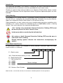
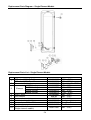
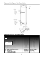
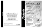
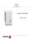
Aquamax Australia Pty Ltd
ABN 17 138 189 689
AQUAMAX SERVICE MANUAL
Stainless Steel Electric Water
Heaters
AQ0903010-A
Revision: A
Published: November 2012
E80 to E315 Series
Contents
Introduction .......................................................................................................................... 3
Safety Warning .................................................................................................................... 3
Heater Model Identification .................................................................................................. 3
Specifications....................................................................................................................... 4
Preventative Maintenance ................................................................................................... 4
Operation ............................................................................................................................. 5
Single Element Models .................................................................................................... 5
Twin Element Non-Simultaneous Models ........................................................................ 5
Components and their Function ........................................................................................... 6
Plumbing Diagrams ............................................................................................................. 7
Fault Finding ........................................................................................................................ 8
Common Faults................................................................................................................ 8
Fault Finding Charts....................................................................................................... 10
General Fault Finding Chart ....................................................................................... 10
Fault Finding Chart 1 – No Hot Water ........................................................................ 11
Fault Finding Chart 2 – Insufficient Hot Water / Water Not Hot Enough ..................... 14
Fault Finding Chart 3 – Water Too Hot....................................................................... 15
Fault Finding Chart 4 – Leaking Water Heater ........................................................... 16
Fault Finding Chart 5 – Noisy Water Heater............................................................... 16
Fault Finding Tests ........................................................................................................ 17
Electrical Insulation Testing ........................................................................................... 19
Component Adjustment Procedures .................................................................................. 20
Thermostat Adjustment .................................................................................................. 20
Component Replacement Procedures ............................................................................... 21
Replacement Parts Diagram – Single Element Models ................................................. 24
Replacement Parts List – Single Element Models ......................................................... 24
Replacement Parts Diagram – Twin Element Models .................................................... 25
Replacement Parts List – Twin Element Models ............................................................ 25
Document Revision History................................................................................................ 26
2
Introduction
The information provided in this manual is based on the water heater being installed in
accordance with the Installation Instructions provided with each water heater.
Should you require further technical advice on an Aquamax Electric Water Heater, contact
your nearest Aquamax Service Department where all genuine replacement parts are also
available.
Safety Warning
The purpose of this Service Manual is to provide sufficient information to allow a person
with the skills as required by the controlling Regulatory Authorities to carry out effective
repairs to an Aquamax Electric Water Heater in the minimum of time.
Safety precautions or areas where extra care should be observed when conducting tests
outlined in this service manual are indicated by print in bold italics and/or a warning
symbol. Take care to observe the recommended procedure.
“Live” testing to be conducted. Personal Protective Clothing (PPE) must
be worn to prevent the risk of electric shock.
Isolate power before conducting the indicated test
Hot surface or liquid. Personal Protective Clothing (PPE) must be worn to
reduce the risk of scalding.
General warning symbol. Observe the instructions accompanying the
symbol.
Heater Model Identification
All identification numbers are designed to convey detailed information about the water
heater to which it is attached.
E
160
S
48
E – Electric series
160 – Rated hot water delivery in Litres
S – Single Heating Unit
T – Two Heating Units
18 – 1800W
24 – 2400W
36 – 3600W
48 – 4800W
Element wattage
SS - Stainless Steel Cylinder
Model number, serial number and date of manufacture should be quoted in all correspondence.
3
SS
Specifications
Specification
Storage capacity (L)
Rated HW delivery (L)
Boost capacity (L) (1)
PTR valve rating (kPa)
ECV rating (kPa)
Max inlet pressure (kPa)
Thermostat setting (°C)
Water connections
With ECV
W/out ECV
Top (1)
Bottom(2)
Inlet (Female)
Outlet (Female)
PTR valve (Female)
E80
83
80
N/A
1400
1250
960
1120
N/A
60 ~ 75
E125
130
125
NA
1400
1250
960
1120
N/A
60 ~ 75
E160
165
160
46
1400
1250
960
1120
60
60 ~ 75
E250
260
250
69
1000
850
650
850
60
60 ~ 75
E315
315
325
79
1000
850
650
850
60
60 ~ 75
RP20 (¾”)
RP20 (¾”)
RP15 (½”)
RP20 (¾”)
RP20 (¾”)
RP15 (½”)
RP20 (¾”)
RP20 (¾”)
RP15 (½”)
RP20 (¾”)
RP20 (¾”)
RP15 (½”)
RP20 (¾”)
RP20 (¾”)
RP15 (½”)
240 Volts 50 Hz AC
Electrical connection
(1)
(2)
Twin element models only.
Factory setting 70°C for twin element models and 65°C for all other single element models.
Preventative Maintenance
Annual Service
It is suggested for peak performance that the water heater be serviced annually.
1. Check for discharge from the PTR valve. When the element is operating a small
discharge of water may be evident. Operate the valve-easing lever to ensure the valve
opens and resets properly. Always open and close the valve gently.
2. Check for discharge from the ECV if fitted. When the element is operating a small
discharge of water may be evident. Operate the valve-easing lever to ensure the valve
opens and resets properly. Always open and close the valve gently.
3. Check for leaks at all tank fittings.
4. Check for signs of excessive corrosion on the water heater jacket.
5. If an overflow tray is installed, check to ensure the overflow tray drain pipe is not
blocked.
6. Isolate power to the water heater and check all electrical connections for signs of
overheating due to poor connection.
7. Conduct an electrical insulation test on the water heater (refer to “Electrical Insulation
Testing” on page 19).
Major Five Year Service
It is recommended that a major five year service be conducted on the water heater.
1. Replace pressure temperature relief valve (PTR).
2. Inspect and flush expansion control valve (if ECV fitted) and replace if required.
3. Check electric heating unit for excessive calcium build up or corrosion and replace
heating unit if required.
4. Visually check water heater for any potential problems.
5. Inspect all plumbing and electrical connections.
4
Operation
Single Element Models
Water temperature is maintained via a thermostat switching the active conductor to an
electric immersion element positioned towards the bottom of the cylinder.
When the water temperature within the cylinder falls sufficiently, the thermostat contacts
close suppling power to the element.
Once the water temperature reaches the set point of the thermostat, the contacts open
cutting power to the element.
A double pole ‘manual reset’ over temperature cut out is incorporated into the thermostat
to provide additional protection in the event the controlling thermostat contacts fail. The
ECO contacts open between 80ºC and 88ºC.
Twin Element Non-Simultaneous Models
Water temperature is maintained via two electric immersion elements, one is positioned
near the top of the cylinder and the other towards the bottom. Only one element is
operational at any time (known as non simultaneous operation).
A thermostat, positioned adjacent to each element is utilised to maintain water
temperature.
The top thermostat switches the neutral from the top element to the bottom element, this
ensures only one element can be energised at a time. The top thermostat is factory set at
60ºC. The bottom thermostat switches the active to the bottom element only.
Both thermostats incorporate a double pole ‘manual reset’ ECO to provide additional
protection in the event the controlling thermostat contacts fail.
Once the top thermostat senses a temperature of approximately 60ºC the thermostat
contacts open the neutral circuit to the top element (between terminals 1 and 2), causing
the top element to be de-energised, and close the neutral circuit to the bottom element
(between terminals 1 and 5).
When the water temperature at the bottom of the tank reaches the set point of the bottom
thermostat, the thermostat contacts open cutting the active circuit to the bottom element.
Under normal usage the top element is unlikely to operate, the water temperature being
maintained by the bottom element. During periods of heavy use when the complete supply
of hot water is depleted, the top element will operate to maintain the water temperature at
the top of the tank (above the top element).
When the bottom element is connected to an off peak tariff full recovery of the tank will
occur whenever power from the off peak tariff is available, usually overnight.
5
Components and their Function
Temperature and Pressure Relief Valve
A valve designed to provide automatic relief by discharging water in case of excessive
temperature, pressure or both.
Never fit a PTR Valve with a pressure rating greater than that indicated on
the product-rating label.
Pressure Limiting Valve (P.L.V.)
A valve that controls its outlet pressure to a predetermined limit.
Stainless Steel Inlet Tube and Diffuser Assembly
A stainless steel tube assembly is installed in the cold water inlet of the water heater
cylinder to assist with stratification.
Thermostat
A device, responsive to temperature, which controls the supply of electrical energy to the
element to maintain the stored water at the required temperature.
Non-simultaneous (Top) Thermostat – Twin Element Models
A device, responsive to temperature, which controls the supply of electrical energy to the
top element to maintain the stored water at the required temperature. It also switches the
neutral supply between the top and bottom elements to ensure only one element can be
operational at any time. This is known as non-simultaneous operation.
Over Temperature Energy Cut Out (E.C.O.)
A temperature-sensing device in combination with the thermostat that automatically cuts
off the supply of electrical energy to prevent excessive water temperature occurring. This
device will not reset automatically but may be manually reset once temperatures have
fallen to a safe level. DETERMINE CAUSE OF OPERATION.
Heating Unit (Element)
A tubular device containing an electric resistance element that converts electrical energy
to heat. Standard ratings are 1.8, 2.4, 3.6, and 4.8 kW.
6
Plumbing Diagrams
The following information and plumbing diagrams are provided as a guide only. For more
information refer to the relevant Installation Instructions.
Two Temperature Zone Plumbing Diagram
Circulated Flow & Return Plumbing Diagrams
For circulated hot water flow and return systems, a temperature limiting device can only be
installed on a dead leg which branches off the circulated hot water flow and return pipe.
Installing a temperature limiting device in the circulated flow and return
pipe work, or circulating tempered water from a temperature limiting device
may cause water to be delivered to ablution areas at a temperature
exceeding the requirements of AS/NZS 3500.4.
7
Fault Finding
Common Faults
When a complaint is lodged about the performance of a hot water system there are a
number of causes that should be checked and eliminated. In an attempt to pinpoint the
most likely cause it is important to discuss with the customer their reasons for the
complaint, the duration of the problem, any change in circumstances or usage and recent
weather conditions. This information in conjunction with the following listed common
complaints will assist you in locating the most likely cause. All procedures assume there is
water flowing through the water heater.
Excessive hot water usage
The complaints of insufficient hot water and no hot water can on many occasions be
attributed to hot water usage exceeding the capacity of the water heater to provide hot
water.
When first attending a call of this nature it is essential to establish the probable hot water
usage by querying the usage habits of the household and compare this with the potential
delivery of the model water heater installed. It can then be established if the usage is
within or outside the capacity of the model. The areas to look at for excessive usage are:
1. Automatic washing machines.
2. Showers exceeding 12 litres/minute for mixed water and 5 minutes in duration.
3. Two or more showers operating at the same time.
4. Change of occupancy or number of persons increased.
5. High water pressure area (Excessive pressure relief valve discharge).
6. Plumbing leaks.
7. Thermostat temperature setting.
8. Crossed connection.
Discoloured water
This may be the result of discoloured water entering from the cold water mains. Check if
the cold water is also discoloured.
Water hammer
A water heater will not cause water hammer, however valves associated with the water
heater may be the source of the problem i.e. cold-water stopcock, non-return valve or relief
valve.
Most water hammer problems are associated with plumbing, hot and cold or appliances
i.e. solenoid valves, ballcocks, loose pipes, sharp angles in pipe work, faulty or worn valve
parts, loose tap washers or neighbouring equipment.
High water pressure areas will have more complaints of this nature and the use of a
pressure-limiting valve (PLV) to reduce the household cold-water pressure will usually
solve most problems.
8
Hot water plumbing leaks
If hot water has not been used for a period of time, feeling the temperature of the hot water
line may give an indication of water flow if the pipe is warm. The method of checking for
plumbing leaks is:
1. Turn off the stopcock on the cold water supply to the water heater.
2. Open a hot tap to ensure the flow of water stops. This will confirm the stopcock is
operating correctly.
3. Turn off the hot tap.
4. Turn on the stopcock to make up the water pressure in the cylinder and then turn the
stopcock off again.
5. Wait approximately 5 minutes then do either of the following:
a. With your ear close to the stopcock turn it on slightly and listen for any water
passing. If there are no leaks, water should not pass.
b. Open a hot tap while listening for any pressure release. If there is a pressure
release there will be no leaks in the plumbing system.
Mixing or crossed connections
If an automatic dishwasher, washing machine, flick mixer tap, tempering valve or
thermostatic mixing valve is installed there is always the possibility that the cold water
could mix with the hot water through a faulty or incorrectly installed valve. This is referred
to as a cross connection. The complaints of insufficient hot water, water not hot enough or
excessive discharge from the pressure relief valve may be attributed to a cross
connection. The method of checking for a cross connection is:
1. Turn off the stopcock on the cold water supply to the water heater.
2. Open a hot tap. If water flow is persistent and cold then a cross connection exists.
9
Fault Finding Charts
General Fault Finding Chart
Chart
1
2
3
4
5
Complaint
No hot water
Insufficient hot water / Water not hot enough
Water too hot
Leaking water heater
Noisy water heater
10
Page
11
14
15
16
16
Fault Finding Chart 1 – No Hot Water
Fault Finding Chart 1.1
11
Fault Finding Chart 1.2
Fault Finding Chart 1.3
12
Fault Finding Chart 1.4
13
Fault Finding Chart 2 – Insufficient Hot Water / Water Not Hot Enough
2
INSUFFICIENT HOT WATER / WATER NOT HOT ENOUGH
Has the usage pattern
changed recently? i.e.
additional appliances or
people using hot water.
Is the heater of sufficient
size for the customers
on going needs?
Refer to sizing guide.
YES
NO
YES
Recommend a water heater of
sufficient capacity to meet the
customers needs.
NO
Is the PTR valve
continuously
discharging water?
Is the water supply
pressure more than
80% of the PTR valve
rating?
YES
YES
NO
Is the correct PTR valve
fitted?
NO
YES
Confirm a recent large draw off of hot water has
not depleted the hot water supply temp. Allow time
for the heater to recover (Note: for models on off
peak tariffs this may not occur until the next day).
Has there been a recent
large draw off of hot
water?
YES
If water heater has a tempering valve installed:
Typically the hot inlet temperature to the tempering
valve must be 10º higher than the required outlet
temperature.
Bottom thermostat if twin
element model
Is cylinder water temp
8ºC less than the
thermostat setting?
YES
Is water heater a single
or twin element model?
NO
Single element model
Twin element model
Is the element(s)
installed in the correct
orientation?
Check for crossed water
connection. Replace PTR valve.
Repair any leaks.
Isolate crossed connections.
YES
NO
NO
Fit pressure limiting valve if not
already installed.
Existing pressure limiting valve
faulty – Replace.
Faulty PTR valve – Replace.
Replace PTR valve with one of
the correct pressure rating.
NOTE: Do not use
reconditioned PTR valves
NO
Are there any plumbing
leaks, crossed
connections or dripping
taps?
Recommend a hot water usage
pattern that will suit the water
heater and the customers needs
1.2
1.3
NO
Install element(s) in correct
orientation.
NO
Check inlet diffuser is not
restricted, missing or damaged.
Check dip tube is not missing
broken or incorrectly fitted.
YES
Clean or replace tempering
valve filters. Refer to
manufacturers instructions for
tempering valve.
NO
Replace tempering valve. Refer
to manufacturers instructions for
tempering valve.
YES
Is a tempering valve
installed?
YES
Are tempering valve
filters blocked?
NO
Is tempering valve outlet
water temp approx
48ºC?
Normal Operation of tempering valve
Tempering valves are generally set to deliver water at 48 - 50ºC.
YES
Depending on the length of pipe work and insulation to the
fixture(s), water temperature can be lower due to heat loss.
NOTE: AS/NZS 3500 Part 4 only requires fixtures used for
ablution purposes to be tempered.
If practical a 2 zone plumbing solution may be offered.
14
Check inlet diffuser is not
restricted, missing or damaged.
Check dip tube is not missing
broken or incorrectly fitted.
Fault Finding Chart 3 – Water Too Hot
15
Fault Finding Chart 4 – Leaking Water Heater
Fault Finding Chart 5 – Noisy Water Heater
16
Fault Finding Tests
Fault Finding Tests 1 – 3
Test 1 – Single Element Models
Test 1 – Twin Element Models
Using a multimeter set on the AC voltage
scale, measure between the Active
terminal ‘A’ and the Neutral terminal ‘N’ on
the terminal block.
Using a multimeter set on the AC voltage
scale, measure between the off peak
Active terminal ‘A1’ and the Neutral
terminal ‘N’ on the terminal block. Then
measure between the boost Active terminal
‘A2’ and the Neutral terminal ‘N’ on the
terminal block. The following results should
be obtained:
Normal voltage is 240 Volts AC.
Active ‘A1’ to Neutral ‘N’ – 240 Volts AC.
Active ‘A2’ to Neutral ‘N’ – 240 Volts AC.
Test 2 – ST Thermostat
Test 3 – ST Thermostat
Using a multimeter set on the resistance
scale, measure between the thermostat
terminals marked ‘3’ and ‘4’ (bottom
thermostat on twin element models).
Using a multimeter set on the resistance
scale, measure between the thermostat
terminals marked ‘1’ and ‘2’ (bottom
thermostat on twin element models).
Normal resistance is less than 1 ohm when Normal resistance is less than 1 ohm when
the ECO contacts are closed.
the thermostat contacts are closed.
17
Fault Finding Tests 4 – 7
Test 4
Test 5
ST thermostat shown
Single element model shown
Disconnect both element wires from the
thermostat and using a multimeter set on
the resistance scale, measure between the
two disconnected element wires.
Using a multimeter on the resistance scale,
measure between the Active wire ‘A’ and
the Neutral wire ‘N’ on the terminal block.
Note: If model is a twin element model,
mark, disconnect and twist ‘A1’ and ‘A2’
actives together to form one active
connection for testing purposes.
Normal resistance is as follows:
1.8kW
2.4kW
3.6kW
4.8kW
element: 29 ~ 35Ω.
element: 22 ~ 26Ω.
element: 15 ~ 17Ω.
element: 11~ 13Ω.
Normal overall resistance when thermostat
is closed will depend on element size.
Refer to test results for test 4.
Test 6 – ST Thermostat
Test 7 – ST Thermostat
Using a multimeter set on the resistance
Using a multimeter set on the resistance
scale, measure between the top thermostat
scale, measure between the top thermostat
terminals marked ‘1’ and ‘2’.
terminals marked ‘3’ and ‘4’.
Normal resistance is less than 1 ohm when
Normal resistance is less than 1 ohm when
the neutral contact to the top element is
the ECO contacts are closed.
closed.
18
Fault Finding Test 8
Test 8 – ST Thermostat
Using a multimeter set on the resistance
scale, measure between the top thermostat
terminals marked ‘1’ and ‘5’.
Normal resistance is less than 1 ohm when
the neutral contact to the bottom element is
closed.
Electrical Insulation Testing
There are three basic test procedures that should be carried out when the operation and
function of a water heater’s electrical system is in doubt.
Personal Protective Equipment should be worn when conducting this
procedure to reduce the risk of electric shock.
To check insulation resistance of the water heater Neutral Circuit (reading not to be
below 1 mega-ohm).
1. Isolate the power supply to the water heater by removing fuse or switching off
circuit breaker. Confirm with a multi-meter across the Active(s) and Neutral
wires at the terminal block that voltage is not present (refer to “Test 1” on page
17).
2. Once satisfied, disconnect the power supply active and neutral wires from the terminal
block. Note: If model is a twin element model, mark and disconnect both active wires
(marked ‘A1’ and ‘A2’).
3. Connect megger leads to the neutral of the water heater wiring and earth.
4. Operate megger on 500 VDC setting. A reading above 1 mega-ohm should be
obtained.
5. If a reading below 1 mega-ohm is obtained, all component parts will need to be
individually tested to locate the fault (refer to “fault finding chart 1.1” on page 11).
19
To check insulation resistance of the water heater Active Circuit (reading not to be
below 1 mega-ohm).
6. Connect megger leads to the active of the water heater wiring and earth. Note: If
model is a twin element model, mark, disconnect and twist ‘A1’ and ‘A2’ actives
together to form one active connection for testing purposes.
7. Operate megger on 500 VDC setting. A reading above 1 mega-ohm should be
obtained.
8. If a reading below 1 mega-ohm is obtained, all component parts will need to be
individually tested to locate the fault (refer to “fault finding chart 1.1” on page 11).
To check “Continuity” of the water heater electrical circuit.
9. Set megger to resistance scale or multimeter to x1 resistance scale and measure
between the active and neutral wires on the water heater. Note: If model is a twin
element model, keep ‘A1’ and ‘A2’ actives twisted together to form one active
connection for testing purposes (previously performed in step 6).
10. If a reading of less than 10 ohms or greater than 35 ohms is obtained, all electrical
component parts will need to be individually tested to locate the fault (refer to “Test 5”
on page 18).
11. Reconnect power supply active cable to ‘A’ terminal and neutral cable to ‘N’ terminal at
heater terminal block. Note: If model is a twin element model, untwist water heater ‘A1’
and ‘A2’ active wires and reconnect to terminal block as per markings.
12. Replace fuse or reset circuit breaker. Note: If continuing with diagnosis procedures
do not replace fuse or reset circuit breaker.
Component Adjustment Procedures
Thermostat Adjustment
The main (bottom) thermostat has been factory preset to 70°C for twin element models
and 65°C for all other single element models. It is possible to adjust this thermostat (60 ~
75°C) but is recommended that the main thermostat’s maximum setting does not exceed
70°C.
The boost (top) thermostat is set to 60°C and is non adjustable.
To adjust the main thermostat:
Personal Protective Equipment should be worn when conducting step 3 of
this procedure to reduce the risk of electric shock.
1.
2.
3.
4.
5.
6.
Isolate the power supply to the water heater by removing fuse
or switching off circuit breaker.
Remove lower access cover.
Confirm with a multi-meter between each Active and Neutral at
the terminal block that voltage is not present.
Turn thermostat temperature adjustment dial clockwise to increase
temperature setting or anticlockwise to decrease temperature
setting.
Replace lower access cover.
Restore the power supply to the water heater.
20
Component Replacement Procedures
Draining the Water Heater (Procedure 1)
Elevated temperatures may be present during the draining process.
Personal Protective Equipment should be worn to prevent the risk of
scalding.
Personal Protective Equipment should be worn when conducting step 3 of
this procedure to reduce the risk of electric shock.
1. Isolate the power and water supplies to the water heater and remove lower access
cover.
2. Relieve pressure from the water heater through PTR valve or a hot tap.
3. Confirm with a multi-meter between each Active and Neutral at the terminal block
that voltage is not present.
4. Disconnect the cold water supply pipe.
5. Fit a drain hose to the cold water connection and run the other end to a drain or safe
location.
6. Open the temperature and pressure relief valve to allow air into the system.
Pressure & Temperature Relief Valve (Procedure 2)
Never fit a PTR valve with a rating higher than that indicated on the water
heater rating plate. Do not use reconditioned PTR valves.
1. Partially drain the water heater (refer to procedure 1).
2. Remove the drain line from the PTR valve.
3. Unscrew the PTR valve and remove.
4. Confirm the replacement PTR valve is the correct rating and refit using thread tape.
5. Refit the drain line.
6. Close the hot tap and restore water supply.
7. Check PTR valve thread for leaks.
8. Operate the PTR valve lever to reset relief drain.
9. Purge air from the system through hot taps.
10.Restore the power supply to the water heater.
Top Thermostat - Non-Simultaneous (Procedure 3)
Personal Protective Equipment should be worn when conducting step 2 of
this procedure to reduce the risk of electric shock.
1. Isolate the power supply to the water heater and remove upper and lower front
covers.
2. Confirm with multi-meter between each Active and Neutral at the terminal block
that voltage is not present.
3. Remove the thermostat protective cover and disconnect the wiring from the thermostat
(Note wiring positions).
21
4. Slide thermostat vertically out of clamp.
5. Remove any scale or corrosion from the cylinder surface.
6. Slide replacement thermostat into place behind clamp and connect wiring to
appropriate points (refer to “Wiring Diagrams” section on page Error! Bookmark not
defined.). Note: Ensure thermostat face is in good contact with cylinder surface.
7. Check water heater internal wiring insulation for cracking.
8. Refit the thermostat protective cover and upper access cover securely.
9. Conduct an electrical insulation test on the water heater (refer to “Electrical Insulation
Testing” on page 19).
10.Replace lower access cover and restore the power supply to the water heater.
Bottom Thermostat – Trade Adjustable (Procedure 4)
Personal Protective Equipment should be worn when conducting step 2 of
this procedure to reduce the risk of electric shock.
1. Isolate the power supply to the water heater and remove access cover.
2. Confirm with multi-meter between each Active and Neutral at the terminal block
that voltage is not present.
3. Remove the thermostat protective cover and disconnect the wiring from the thermostat
(Note wiring positions).
4. Slide thermostat vertically out of clamp. Note the current temperature selected.
5. Remove any scale or corrosion from the cylinder surface.
6. Slide replacement thermostat into place behind clamp, set temperature to that noted in
step 4 and connect wiring to appropriate points (refer to “Wiring Diagrams” section on
page Error! Bookmark not defined.). Note: Ensure thermostat face is in good contact
with cylinder surface.
7. Check water heater internal wiring insulation for cracking.
8. Conduct an electrical insulation test (refer to “Electrical Insulation Testing” on page 19).
9. Refit the thermostat protective cover and the lower access cover.
10.Restore the power supply to the water heater.
Element – Top and Bottom (Procedure 5)
Elevated temperatures may be present during element removal process.
Personal Protective Equipment should be worn to prevent the risk of
scalding.
When a fault or leak is traced to the element, the water heater should be drained to
prevent damage to flooring or floor coverings by accidental flooding.
1. Drain the water heater (refer to procedure 1).
2. When the water heater is drained, undo the four element screws, removing thermostat
clamp first.
3. Withdraw the element. Care must be taken to ensure the loop of the element does not
catch in the cylinder opening and open out inside the cylinder.
22
NOTE: Do not cut off the element and leave a portion inside the cylinder.
4. Clean around cylinder fitting, fit a new gasket to the new element and slide the element
into the cylinder (reverse to step 3) taking care that it is in the correct orientation.
Refer to element flange for orientation directions. Note: Never reuse old element
gaskets.
5. Replace screws and thermostat clamp and tighten. Note: The
element retaining screws are tightened only until the return edge
bottoms on the tank flange – do not over tighten.
6. The earthing of the internal storage cylinder relies on a good
electrical contact between the metal surround of the element flange
and the cylinder barrel flange.
An earth continuity test should be performed whenever an element
or element gasket is replaced, adjusted or serviced in any way. This
continuity test is performed between the heaters internal storage
cylinder and the main earth terminal of the water heater with a
resulting reading of not more than 0.5 ohms as required by AS/NZS
3000 6.3.3.2.
7. Restore cold water supply and fill the storage tank. Release air by gently lifting the
easing lever on the PTR valve until water runs from the drain or opening hot taps.
8. Check for water leaks around the element flange.
9. Conduct an electrical insulation test (refer to “Electrical Insulation Testing” on page
19).
10. Replace access cover securely and restore the power supply to the water heater.
23
Replacement Parts Diagram – Single Element Models
Replacement Parts List – Single Element Models
Item
1
2
3
4
5
6
7
8
9
10
Description
PTR valve 1000 kPa x ½”
PTR valve 1400 kPa x ½”
Thermostat (bottom)
1800W Incoloy
2400W Incoloy
Element
3600W Incoloy
4800W Incoloy
Access cover
Seal element
Retainer thermostat
Electrical safety shield
Screw, element M8 x 20 Hex
Washer star
Terminal block, 2 way
(Single element models)
Part Number
AQ0262003
AQ0262006
AQ0203015
AQ0200572
AQ0200573
AQ0200575
AQ0200576
AQ2053002
050704
102501
AQ0203017
AQ0100113
AQ0104203
AQ0211501
24
Remarks
(250L – 315L)
(80L – 160L)
Adjustable 60 ~ 75°C
(80L - 160L)
(80L - 250L)
(80L – 315L)
(125L – 315L)
(80L - 315L)
(80L - 315L)
(80L - 315L)
For thermostat
Steel Zinc Plated
Zinc Plated
(80L - 315L)
Replacement Parts Diagram – Twin Element Models
Replacement Parts List – Twin Element Models
Item
1
2
3
5
5
6
7
8
9
10
11
Description
PTR valve 1000 kPa x ½”
PTR valve 1400 kPa x ½”
Thermostat boost (top)
Thermostat (bottom)
1800W Incoloy
2400W Incoloy
Element
3600W Incoloy
4800W Incoloy
Access cover
Seal element
Retainer thermostat
Electrical safety shield
Screw, element M8 x 20 Hex
Washer star
Terminal block, 3 way
(Twin element models)
Part Number
AQ0262003
AQ0262006
AQ0203016
AQ0203015
AQ0200572
AQ0200573
AQ0200575
AQ0200576
AQ2053002
050704
102501
AQ0203017
AQ0100113
AQ0104203
AQ0211501
25
Remarks
(250L – 315L)
(160L)
60°C non adjustable
Adjustable 60 ~ 75°C
(160L)
(160L - 250L)
(160L – 315L)
(160L – 315L)
(160L - 315L)
(160L - 315L)
(160L - 315L)
For thermostat
Steel Zinc Plated
Zinc Plated
(160L - 315L)
Document Revision History
Title: Aquamax Stainless Steel Electric Service Manual
Revision
A
Details of change
Service Manual issued
Revision Date: 15/11/2012
Document No:
AQ0903010-A
D.O.I.
15/11/12
AQ0903010-A
NOTE: Every care has been taken to ensure accuracy in preparation of this publication. No liability can be
accepted for any consequences, which may arise as a result of its application.
26