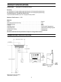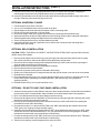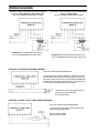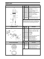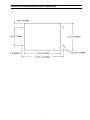
1
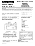
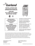
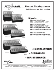
TANKWATCH 4
®
LEVEL MONITOR SYSTEM
OWNER’S MANUAL
Dometic Corporation • Sanitation Systems
13128 State Rt 226, PO Box 38
Big Prairie, OH 44611
SeaLand Product Customer Service: 1-800-321-9886
(8:00 a.m. - 5:00 p.m. ET)
1
TABLE OF CONTENTS
Safety Instructions . . . . . . . . . . . . . . . . . . . . . . . 2
Product Features . . . . . . . . . . . . . . . . . . . . . . . . 2
Models and Accessories . . . . . . . . . . . . . . . . . . . 2
Dimensional Specifications . . . . . . . . . . . . . . . . . 3
Product Specifications . . . . . . . . . . . . . . . . . . . . . 3
Installation Instructions . . . . . . . . . . . . . . . . . 4 - 5
Wiring Diagrams . . . . . . . . . . . . . . . . . . . . . . . . . 6
Parts List . . . . . . . . . . . . . . . . . . . . . . . . . . . . . . 7
Manufacturer’s One-Year Limited Warranty . . . . . 8
Control Panel Mounting Template
SAFETY INSTRUCTIONS
WARNING: When using this device, always exercise basic safety precautions, including the following:
• Read all instructions before installation or use.
• Never connect this device to any electrical circuit with other than 12 or 24 volt Direct Current or exceed
the amperage draw listed below.
• Never install the indicator panel in an atmosphere with potentially flammable or explosive vapors.
• Never install the probe cap with float switches into a tank that contains anything other than fresh, gray or
black water.
CAUTION: Dropping or rough handling of float switches may result in damage.
PRODUCT FEATURES
•
•
•
•
•
•
•
•
Eliminates false reading from fouled probes.
Three float switches, four level indications for all tanks up to 22-inch (559mm) & 45-inch (114cm) in depth.
Deluxe panel complements bathroom decor and provides international symbology.
Installs in any rigid tank with optional 3-inch NPT mounting flange.
One model operates on 12 or 24 VDC.
Probe cap provides clean out for easy access to interior of tank.
Cap is available with or without 5/8" vent hose connection.
Optional shut-off relay plugs into back of circuit board to shut down toilet or water system when gray or
black water tank is full or when freshwater tank is empty.
• Always one level light on to confirm that electrical power is applied.
• Only one level light on at a time to eliminate confusion and save battery power.
• CE and IMCI approved for electromagnetic compatibility.
The TankWatch 4 Level Monitor System is designed to permit remote sensing of liquid levels in wastewater, gray
water or potable fresh water tanks. The TankWatch 4 utilizes three micro-float switches, which activate a fourlight panel. One is fixed and activates a full light when the liquid is within approximately 2-inches of the top
inside surface of the tank. The other two float switches are mounted on adjustable stems and can be positioned
to within 2-inches of the bottom of the tank. The stems are semi-flexible and are designed to flex with the
sloshing of the tank contents. A simple procedure allows one adjustable stem to sense when the tank is empty
and the other adjustable stem to sense when the tank is 1/4 or 1/2 full, depending on the application.
MODELS AND ACCESSORIES
Part Number
313600113
313600114
313600115
313600116
307230272
600341292
600342490
385318714
360600212
360600224
Description
TankWatch 4 Panel and Cap with Vent, 22-inch Probes
TankWatch® 4 Panel and Cap without Vent, 22-inch Probes
TankWatch® 4 Panel and Cap with Vent, 45-inch Probes
TankWatch® 4 Panel and Cap without Vent, 45-inch Probes
Universal Flange (3-inch NPT) with gasket and stainless steel hardware
Plug In Relay, 12VDC
Plug In Relay, 24VDC
“Do Not Flush” Panel
TankWatch® 4 Panel with 12VDC Relay
TankWatch® 4 Panel with 24VDC Relay
®
2
PRODUCT SPECIFICATIONS
TankWatch® 4 Level Monitor System
Product Name:
Electrical:
12 Volts DC @ .017 amps (without optional relay) and .152 amps (with optional relay)
24 Volts DC @ .014 amps (without optional relay) and .072 amps (with optional relay)
Float Switch Rating = 20 watts with resistive load
12-pin terminal block allows up to one 12-gauge wire per position
Maximum Tank Pressure: 25 PSI
Materials:
Float . . . . . . . . . . . . . . . . . . . . . . . . . . . . . . . . . . . . . . . . . . . . . . . . . . . . . . .
Tank Mounted Float Switch Cap . . . . . . . . . . . . . . . . . . . . . . . . . . . . . . . . . . .
Float Switch Body . . . . . . . . . . . . . . . . . . . . . . . . . . . . . . . . . . . . . . . . . . . . .
O-Rings . . . . . . . . . . . . . . . . . . . . . . . . . . . . . . . . . . . . . . . . . . . . . . . . . . . . .
Adjustable Stems . . . . . . . . . . . . . . . . . . . . . . . . . . . . . . . . . . . . . . . . . . . . . .
Compression Nut . . . . . . . . . . . . . . . . . . . . . . . . . . . . . . . . . . . . . . . . . . . . . .
Control Panel Housing . . . . . . . . . . . . . . . . . . . . . . . . . . . . . . . . . . . . . . . . . .
Face Plate . . . . . . . . . . . . . . . . . . . . . . . . . . . . . . . . . . . . . . . . . . . . . . . . . . .
Buna N
PVC
ABS
Nitrile
Cross Linked Polypropylene
Glass Reinforced Polypropylene
Polypropylene
Polycarbonate
Electrical and dimensional specifications subject to change without notice.
DIMENSIONAL SPECIFICATIONS
*
4 3/4"
[121mm]
Minimum Clearance
(Behind Wall)
* Max length for 45-inch probes
is 43 3/4-in. (1111mm).
3
INSTALLATION INSTRUCTIONS
ADJUSTABLE LEVEL INDICATOR CAP
1. The adjustable level indicator cap is designed for a 3-inch FPT opening. Order P/N 230272 if tank is
made of rigid material and not a SeaLand holding tank.
2. Loosen the compression nuts on the adjustable stem bosses and install the cap into the tank. Slide the #1
stem (see dimensional specifications on previous page) down until the float touches the bottom of the tank.
Tighten #1 compression nut and mark the stem at the top of the nut with a pen or pencil. Do not cut the
stem at this mark. Loosen the compression nut and slide the stem up and carefully cut the #1 stem 1-5/8 inch
(41.3mm) below the mark without damaging the switch wires. Pull the wires through the black wire cover
and push the stem down into the compression nut until the black wire cover touches the compression nut.
3. Remove the cap from the tank and adjust the #2 stem for 1/2 full level for gray and black water tanks or 1/4
full level for fresh water tanks. Tighten the compression nut and cut the stem off 3/8-inch (9.5mm) above the
compression nut without damaging the switch wires. Slip the black wire cover on to the top of the stem.
4. To make the #1 float switch activate the empty light, the float must be positioned with the recessed shoulder
at the bottom. Remove the C-clip from the switch body and flip the float 180 degrees and replace the C-clip.
(See Diagram #1.)
5. The #2 float switch can activate the mid light on black and gray water tanks and activate the low light on
freshwater tanks. The recessed shoulder should be up for black and gray water tanks and down for
freshwater tanks. (See Diagram #2.)
6. Route 18-gauge stranded copper wire from the indicator panel to the float switch cap. Use quick disconnect
terminals on float switch wires to prevent twisting wires when removing the cap. With cap removed from the
tank, connect the wires according to the wiring diagram and test the floats by moving them up and down.
Disconnect the wires and install the cap with the O-ring into the tank, then reconnect the wires.
7. For caps with vents, route 5/8-inch vent hose from the thru-hull fitting to the vent connection on the float
switch cap. Use stainless steel hose clamps to secure the vent hose connections.
Diagram #1
Diagram #2
FRESHWATER TANK
(POTABLE WATER)
WASTE TANK
(BLACK & GRAY WATER)
RECESSED
SHOULDER
UP
RECESSED
SHOULDER
DOWN
CONTROL PANEL
1. Select a mounting location away from direct contact with water and oil. Dry locations in the bathroom,
salon or galley are most desirable.
2. Confirm clearances for the panel behind walls, hull liner or bulkhead.
3. Cut out mounting hole for control panel. (See template for cut-out and hole locations.)
4. Do not mount the control panel until wiring is routed and secured to the terminal block or rear of the
control panel housing.
5. Route wiring following one of the wiring diagrams for black, gray or fresh water applications.
6. Include wiring for any of the optional electrical accessories that may be part of the installation and shown
in separate wiring diagrams.
7. Mount the control panel with the (4) #6 x 1-inch long black, oval-head screws provided.
8. Determine which tank application the control panel will be monitoring and insert the appropriate color
light and matching lens into the correct location following the chart below.
Tank Application
Waste (Black) Water
Gray Water
Fresh Water
Empty
Green
Green
Red
Light & Lens Color Location
Low
Mid
Amber
Amber
Yellow
Yellow
Yellow
Amber
4
Full
Red
Red
Green
INSTALLATION INSTRUCTIONS (con’t.)
9. Insert the correct color lens in the appropriate hole from the front side of the face plate, snapping the
matching light into the lens firmly. Repeat with the three (3) remaining lens and lights.
10. Insert the (2) small tabs on the left side of the face plate into the housing and snap the large center tab on
the right of the face plate into the housing to secure it.
OPTIONAL UNIVERSAL FLANGE
1.
2.
3.
4.
5.
6.
7.
8.
9.
Find and mark the top center of the tank.
Cut a 4 1/16-inch diameter hole in the top center of the tank.
Slip the flange into the hole and mark the location of the five mounting holes.
Drill the five mounting holes with a 1/4-inch drill bit.
Remove the flange, clean all oils, grease and dirt from the mounting surface and allow to dry.
Apply liberal amounts of silicone rubber adhesive to the mounting surface and the underside of the flange.
Insert the gasket into the flange and align with the five mounting holes.
Secure the flange with the screws, nuts and washers provided.
Install the float switch cap and, if applicable, secure the 5/8-inch vent hose to the vent fitting with a
stainless steel hose clamp.
OPTIONAL RELAY INSTALLATION
CAUTION: VERIFY THAT RELAY IS CORRECT VOLTAGE FOR SYSTEM (12VDC requires P/N 341292 and
24VDC requires P/N 342490).
1. Remove the face plate from the housing by prying the right side center tab of face plate from the housing
with a small screwdriver. Allow the face plate to be suspended by the light wires.
2. Remove the four housing mounting screws and pull the housing out of the wall or hull liner, exposing the
wiring terminal block at the rear of the housing.
3. Mark the wires for terminal block pin location before removing.
4. Remove all wires from the terminal block.
5. Remove the (2) screws securing the circuit board to the housing.
6. Slide the circuit board from the housing and insert the relay into the socket on the rear of the circuit board.
7. Reinstall the circuit board.
8. Route the additional wires (use 12 or 14 gauge stranded copper) to pin 10 and 11 to interrupt power for the
toilet or water system, depending on the tank application. (See optional relay wiring diagram for
application details.)
9. Reinstall all other wires. Turn on power and test circuit.
OPTIONAL “DO NOT FLUSH” (DNF) PANEL INSTALLATION
1. Select a mounting location in the bathroom away from direct contact with water. A location above and behind
the toilet at eye level is most desirable. Allow clearance for the toilet lid/seat when in the up position.
2. Drill a 1/2-inch diameter hole for the lamp clearance and wire routing.
3. Remove the face plate from the TankWatch 4 (TW4) housing by prying the right side of the face plate center
tab from the housing using a small screw driver.
4. Remove the four housing mounting screws and pull the housing out of the wall of hull liner exposing the
terminal block on the rear of the housing.
5. Route wires from pins 1 or 2 and pin 8 of the TW4 to the “DNF” panel through the clearance hole for the
“DNF” panel. (Use 18 gauge or larger stranded copper.)
6. Install the current limiting resistor supplied with the “DNF” panel between the white wire on the “DNF” panel
and the wire from the TW4 terminal block pin 1 or 2 (see optional Do Not Flush wiring diagram for details).
Insulate the connection with vinyl electrical tape or shrink tubing.
7. Connect the orange wire from the “DNF” panel to the wire from pin 8 of the terminal block on the TW4 panel.
Insulate the connection with vinyl electrical tape or shrink tubing.
8. Test the circuit and then mount both panels to the wall or hull liner.
5
WIRING DIAGRAMS
TANKWATCH 4 TANK LEVEL MONITOR SYSTEM RECOMMENDED
WIRING FOR WATER TANKS.
USE 18GA. STRANDED COPPER WIRE OR LARGER.
TANKWATCH 4 TANK LEVEL MONITOR SYSTEM RECOMMENDED
WIRING FOR WASTE WATER AND GRAY WATER TANKS.
USE 18GA. STRANDED COPPER WIRE OR LARGER.
PLEASE NOTE THAT THE RECESSED SHOULDER OF
THE FLOAT IS DOWNWARD ON THE EMPTY FLOAT.
PLEASE NOTE THAT THE RECESSED SHOULDER OF THE
FLOAT IS DOWNWARD ON THE EMPTY AND 1/4 MID FLOAT.
OPTIONAL PLUG-IN RELAY WIRING DIAGRAM
USE 12 OR 14 GAUGE COPPER STRANDED WIRE.
WITH RELAY INSTALLED, AND THE TANKWATCH 4 WIRED FOR A WASTE
(BLACK) WATER TANK. THE TANK FULL FLOAT SWITCH WILL SHUT OFF
ELECTRICAL POWER TO THE TOILET SYSTEM. WHEN THE TANKWATCH 4
IS WIRED FOR A FRESH WATER TANK, THE EMPTY FLOAT SWITCH WILL
SHUT OFF THE WATER PUMP WHEN THE TANK IS EMPTY.
*
*Consult toilet or water system specifications for
proper fusing or circuit breaker size.
Do not exceed 30 amps.
OPTIONAL “DO NOT FLUSH” PANEL WIRING DIAGRAM
USE 16 OR 18 GAUGE COPPER STRANDED WIRE.
UP TO 4 “DO NOT FLUSH” PANELS CAN BE USED WITH ONE
TANKWATCH 4 INDICATOR PANEL.
PIN 1 FOR 12VDC SYSTEMS
PIN 2 FOR 24VDC SYSTEMS
6
PARTS LIST
TankWatch 4 Probe Cap
Item
1
2
3
4
5
6
6
7
8
9
10
11
12
Part
Number
600342260
385310258
600347587
600340425
600342238
600342114
600342115
600342262
600343657
600340423
600340424
385230268
385230930
Description
Wire Cover, Pull Tab Cap
Compression Nut/Washer Kit
Cap O-Ring
Reed Switch Stem (threaded)
Polyethylene Tubing
Adjustable Level Cap with Vent
Adjustable Level Cap without Vent
Wire Cover, Pull Tab Cap
Reed Switch Stem (barbed)
Reed Float
Ring Clip
Float Stem Kit (incl. items 4, 9, 10)
Probe Kit (incl. items 5, 8-10)
NOTE: If it is necessary to remove or replace the Float
Switch Assembly (item 4) be sure to use the O-ring
and tighten switch to 8-10 inch-lbs. Over-tightening is
not necessary and will cause damage to the parts.
TankWatch 4 Panel
Item
1
2
3
4
5
6
7
8
9
*10
Part
Number
600342400
600340471
600343662
600343661
600342495
600343598
600342494
600342493
600340488
385310693
600341292
600342490
385310666
Description
Housing, Indicator Panel
Screw, #6 x 1" Phillips, Oval Head
TankWatch 4 Face Plate - Black
TankWatch 4 Face Plate - White
Lens, Green
Lens, Yellow
Lens, Amber
Lens, Red
Screw, #6 x 3/8" Pan Head, Phillips
TankWatch 4 Control Panel
Optional 12VDC Relay
Optional 24VDC Relay
TankWatch 4 Indicator Panel
(items 1-9) (not shown)
* Standard with Part Nos. 360600212 and 360600224 only.
Universal Flange Adapter
Item
1
2
3
7
Part
Number
Description
600340406 Universal Mounting Flange
600340407 Universal Mounting Flange Gasket
307230272 Universal Mounting Flange Kit
(Complete with items 1, 2, mounting
hardware and instructions.)
MANUFACTURER’S ONE-YEAR LIMITED WARRANTY
Dometic Corporation warrants, to the original purchaser only, that this product, if used for personal, family or household
purposes, is free from defects in material and workmanship for a period of one year from the date of purchase.
If this Dometic product is placed in commercial or business use, it will be warranted, to the original purchaser only, to be
free of defects in material and workmanship for a period of ninety (90) days from the date of purchase.
Dometic reserves the right to replace or repair any part of this product that proves, upon inspection by Dometic, to be
defective in material or workmanship. All labor and transportation costs or charges incidental to warranty service are to be
borne by the purchaser-user.
EXCLUSIONS
IN NO EVENT SHALL DOMETIC BE LIABLE FOR INCIDENTAL OR CONSEQUENTIAL DAMAGES, FOR DAMAGES
RESULTING FROM IMPROPER INSTALLATION, OR FOR DAMAGES CAUSED BY NEGLECT, ABUSE, ALTERATION OR
USE OF UNAUTHORIZED COMPONENTS. ALL IMPLIED WARRANTIES, INCLUDING ANY IMPLIED WARRANTY OF
MERCHANTABILITY OR FITNESS FOR ANY PARTICULAR PURPOSE, ARE LIMITED TO A PERIOD OF ONE YEAR FROM
DATE OF PURCHASE.
IMPLIED WARRANTIES
No person is authorized to change, add to, or create any warranty or obligation other than that set forth herein.
Implied warranties, including those of merchantability and fitness for a particular purpose, are limited to one (1) year from
the date of purchase for products used for personal, family or household purposes, and ninety (90) days from the date of
purchase for products placed in commercial or business use.
OTHER RIGHTS
Some states do not allow limitations on the duration of an implied warranty and some states do not allow exclusions or
limitations regarding incidental or consequential damages; so, the above limitations may not apply to you. This warranty
gives you specific legal rights, and you may have other rights which may vary from state to state.
To obtain warranty service, first contact your local dealer from whom you purchased this product.
Dometic Corporation • Sanitation Systems
13128 State Rt 226, PO Box 38
Big Prairie, OH 44611
SeaLand Product Customer Service: 1-800-321-9886
(8:00 a.m. - 5:00 p.m. ET)
Email: [email protected]
600343591 8/03
® Formica is a registered trademark of Formica Corp.
® Registered; ™ Trademark of Dometic Corporation
© Dometic Corporation
8
CONTROL PANEL MOUNTING TEMPLATE
9