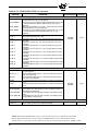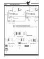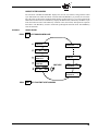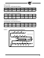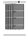
1
® BL-1001 MARCH 9, 2015 YB110/YB230 FIREYE® BurnerLogiX™ MICROPROCESSOR-BASED INTEGRATED BURNER MANAGEMENT CONTROL APPROVED DESCRIPTION The Fireye® BurnerLogix™ System is a microprocessor based burner management control system designed to provide the proper burner sequencing, ignition and flame monitoring protection on automatically ignited oil, gas, and combination fuel burners. In conjunction with limit and operating controls, it programs the burner/blower motor, ignition and fuel valves to provide for proper and safe burner operation. Through SMART LED’S, the control provides current operating status and lockout information in the event of a safety shutdown. Optional VFD and LCD displays are available that may be either plugged in or mounted remotely to give full language descriptors of current status and diagnostic lockout information. Refer to BurnerLogix PROGRAMMER SELECTION later in this document for the various combinations of programmer and display modules. A complete BurnerLogix system includes the YB110 (YB230) chassis equipped with the type of flame amplifier required for the application, appropriate flame detector, plug-in programmer module, wiring base and optional alpha-numeric display. Interchangeable programmer modules allow for complete versatility in selection of function, timing and flame failure response times. The optional alpha-numeric display has 2 lines by 16 characters per line. It is available in either vacuum fluorescent or liquid crystal formats. The advantage of VFD is high brightness and extended temperature range down to –40°F. Both displays contain a fully functional keypad. You can easily scroll through the various menus to view the current operating status, review programmer configuration, and lockout history. When mounted remotely, the displays provide NEMA 4x(IP66) protection. An advantage of the BurnerLogix control family is the ability to set many of the operating parameters associated with proper and reliable burner operation allowing inventory of various programmer types to be kept to a minimum. The YB110 (YB230) is a chassis/flame amplifier module complete with mounting screws and blank display module. The display module (BLV512 (vfd) or BLL510 (lcd)), if required, must be ordered separately. Interchangeable YP programmer modules allow for complete versatility in selection of control function, timing, and flame scanning means. Functions such as pre-purge time, recycling or non-recycling interlocks, high fire proving interlock, and trial for ignition timing of the pilot and main flame are determined by the programmer module. The BurnerLogix system can be used with ultra-violet, auto-check infrared, flame rod, self-check ultra-violet flame scanners or direct coupled integrated scanners by choosing the proper chassis/flame amplifier module. 1 Wiring bases for the BurnerLogix control are available pre-wired with 4 foot (1.2m) lead wires color coded and marked for easy installation or with an integral terminal block capable of a accepting up to 2 X 14 AWG wires. The wiring base terminal block is available with knockouts for conduit or open ended for cabinet mounting. The pigtail wiring base is 4" X 5" (101.6mm x 127mm) and the terminal block wiring base is 4" X 7" (101.6mm x 177.8mm). Additional functions of the BurnerLogix system include: • • • • • • • • • • • • • A non-volatile memory allows the control to remember its history and present position even when power is interrupted. A consistent flame signal read-out via display module or 4-20 mA output. Read-out of main fuel operational hours and complete cycles via display module. Modbus communications via RS485 multi-drop link. Proof of fuel valve closure during the off cycle. Burn-in time of program parameters occurs after 8 hours of main valve on time. A run/check switch allows the operator to stop the program sequence in any of four different positions (Purge, PTFI, MTFI or Auto). Remote Display mounting with NEMA 4 protection. Remote Reset. Programmable communication baud rate allows for DCS compatibility. Keypad selectable language readout. Revert to pilot can increase burner turn down. Additional terminals provided for applications requiring additional inputs and outputs. CAUTION: While programmers are mechanically interchangeable in that they mate with a common chassis/amplifier module, you must select the correct model for your application. Inappropriate application of a control can result in an unsafe condition hazardous to life and property. Selection of a control for a particular application must be made by a competent professional, such as a boiler/burner service technician licensed by a state or other government agency. NOTICE: This equipment generates and can radiate radio frequency energy, and if not installed and used in accordance with the instruction manual may cause interference to radio communications. It has been tested and found to comply with the limits for a Class A computing device pursuant to Subpart J of part 15 of FCC Rules, which are designed to provide reasonable protection against such interference when operated in a commercial environment. Operation of this equipment in a residential area may cause interference in which case the user, at his own expense, will be required to take whatever measures which may be required to correct the interference. 2 ® TABLE OF CONTENTS BURNERLOGIX SPECIFICATIONS . . . . . . . . . . . . . . . . . . . . . . . . . . . . . . . . . . . . . . . . . . . . . . . . . . . . . . . . . . . . . . 4 PART NUMBERS AND APPROVALS . . . . . . . . . . . . . . . . . . . . . . . . . . . . . . . . . . . . . . . . . . . . . . . . . . . . . . . . . . . . . 7 ORDERING INFORMATION . . . . . . . . . . . . . . . . . . . . . . . . . . . . . . . . . . . . . . . . . . . . . . . . . . . . . . . . . . . . . . . . . . . . 8 INSTALLATION PROCEDURE . . . . . . . . . . . . . . . . . . . . . . . . . . . . . . . . . . . . . . . . . . . . . . . . . . . . . . . . . . . . . . . . . 12 WIRING BASE. . . . . . . . . . . . . . . . . . . . . . . . . . . . . . . . . . . . . . . . . . . . . . . . . . . . . . . . . . . . . . . . . . . . . . . . . . . . . . . . . . . . . . . . . . . . . . . PTFI*MTFI TIMINGS . . . . . . . . . . . . . . . . . . . . . . . . . . . . . . . . . . . . . . . . . . . . . . . . . . . . . . . . . . . . . . . . . . . . . . . . . . . . . . . . . . . . . . . . . LED INDICATOR LIGHTS . . . . . . . . . . . . . . . . . . . . . . . . . . . . . . . . . . . . . . . . . . . . . . . . . . . . . . . . . . . . . . . . . . . . . . . . . . . . . . . . . . . . . REPLACEABLE FUSE . . . . . . . . . . . . . . . . . . . . . . . . . . . . . . . . . . . . . . . . . . . . . . . . . . . . . . . . . . . . . . . . . . . . . . . . . . . . . . . . . . . . . . . . 12 15 16 17 DESCRIPTION OF FUNCTIONS OF OPERATING CONTROLS . . . . . . . . . . . . . . . . . . . . . . . . . . . . . . . . . . . . . . 18 SETTING PROGRAMMER PARAMETERS . . . . . . . . . . . . . . . . . . . . . . . . . . . . . . . . . . . . . . . . . . . . . . . . . . . . . . . 18 KEYPAD DESCRIPTION . . . . . . . . . . . . . . . . . . . . . . . . . . . . . . . . . . . . . . . . . . . . . . . . . . . . . . . . . . . . . . . . . . . . . . . . . . . . . . . . . . . . . . 19 PROGRAM SET UP SUB-MENU . . . . . . . . . . . . . . . . . . . . . . . . . . . . . . . . . . . . . . . . . . . . . . . . . . . . . . . . . . . . . . . . 20 TO VIEW AND MODIFY A PROGRAMMABLE PARAMETER . . . . . . . . . . . . . . . . . . . . . . . . . . . . . . . . . . . . . . . . . . . . . . . . . . . . . . 21 FLAME SCANNERS . . . . . . . . . . . . . . . . . . . . . . . . . . . . . . . . . . . . . . . . . . . . . . . . . . . . . . . . . . . . . . . . . . . . . . . . . . 22 INSTALLATION - UV SCANNERS . . . . . . . . . . . . . . . . . . . . . . . . . . . . . . . . . . . . . . . . . . . . . . . . . . . . . . . . . . . . . . . . . . . . . . . . . . . . . . OPERATION — 45UV5 & 55UV5 SELF-CHECKING UV SCANNER . . . . . . . . . . . . . . . . . . . . . . . . . . . . . . . . . . . . . . . . . . . . . . . . . . WIRING - UV SCANNERS . . . . . . . . . . . . . . . . . . . . . . . . . . . . . . . . . . . . . . . . . . . . . . . . . . . . . . . . . . . . . . . . . . . . . . . . . . . . . . . . . . . . . INSTALLATION—INFRARED SCANNER TYPE 48PT2 . . . . . . . . . . . . . . . . . . . . . . . . . . . . . . . . . . . . . . . . . . . . . . . . . . . . . . . . . . . . OPERATION - IR LEARN . . . . . . . . . . . . . . . . . . . . . . . . . . . . . . . . . . . . . . . . . . . . . . . . . . . . . . . . . . . . . . . . . . . . . . . . . . . . . . . . . . . . . . INSTALLATION - 69ND1 FLAME ROD . . . . . . . . . . . . . . . . . . . . . . . . . . . . . . . . . . . . . . . . . . . . . . . . . . . . . . . . . . . . . . . . . . . . . . . . . . INSTALLATION - 85 SERIES PHOENIX SCANNER. . . . . . . . . . . . . . . . . . . . . . . . . . . . . . . . . . . . . . . . . . . . . . . . . . . . . . . . . . . . . . . . . . INSTALLATION - 95 SERIES INSIGHT SCANNERS . . . . . . . . . . . . . . . . . . . . . . . . . . . . . . . . . . . . . . . . . . . . . . . . . . . . . . . . . . . . . . . . . 22 23 24 24 25 27 28 30 SYSTEM INFO SUB-MENU . . . . . . . . . . . . . . . . . . . . . . . . . . . . . . . . . . . . . . . . . . . . . . . . . . . . . . . . . . . . . . . . . . . . 33 SYSTEM OPERATION . . . . . . . . . . . . . . . . . . . . . . . . . . . . . . . . . . . . . . . . . . . . . . . . . . . . . . . . . . . . . . . . . . . . . . . . 33 YP100 OPERATING SEQUENCE. . . . . . . . . . . . . . . . . . . . . . . . . . . . . . . . . . . . . . . . . . . . . . . . . . . . . . . . . . . . . . . . . . . . . . . . . . . . . . . . START-UP (NORMAL CYCLE) . . . . . . . . . . . . . . . . . . . . . . . . . . . . . . . . . . . . . . . . . . . . . . . . . . . . . . . . . . . . . . . . . . . . . . . . . . . . . . . . . YP200 OPERATING SEQUENCE. . . . . . . . . . . . . . . . . . . . . . . . . . . . . . . . . . . . . . . . . . . . . . . . . . . . . . . . . . . . . . . . . . . . . . . . . . . . . . . . YP300 OPERATING SEQUENCE. . . . . . . . . . . . . . . . . . . . . . . . . . . . . . . . . . . . . . . . . . . . . . . . . . . . . . . . . . . . . . . . . . . . . . . . . . . . . . . . YP138 PROGRAMMER . . . . . . . . . . . . . . . . . . . . . . . . . . . . . . . . . . . . . . . . . . . . . . . . . . . . . . . . . . . . . . . . . . . . . . . . . . . . . . . . . . . . . . . 34 35 37 38 40 LOCKOUTS . . . . . . . . . . . . . . . . . . . . . . . . . . . . . . . . . . . . . . . . . . . . . . . . . . . . . . . . . . . . . . . . . . . . . . . . . . . . . . . . . 44 SAFETY SHUTDOWN . . . . . . . . . . . . . . . . . . . . . . . . . . . . . . . . . . . . . . . . . . . . . . . . . . . . . . . . . . . . . . . . . . . . . . . . . . . . . . . . . . . . . . . . . . DIAGNOSTIC MESSAGES. . . . . . . . . . . . . . . . . . . . . . . . . . . . . . . . . . . . . . . . . . . . . . . . . . . . . . . . . . . . . . . . . . . . . . . . . . . . . . . . . . . . . RESETTING THE CONTROL. . . . . . . . . . . . . . . . . . . . . . . . . . . . . . . . . . . . . . . . . . . . . . . . . . . . . . . . . . . . . . . . . . . . . . . . . . . . . . . . . . . LOCKOUT CODES . . . . . . . . . . . . . . . . . . . . . . . . . . . . . . . . . . . . . . . . . . . . . . . . . . . . . . . . . . . . . . . . . . . . . . . . . . . . . . . . . . . . . . . . . . . LOCKOUT HISTORY SUB-MENU . . . . . . . . . . . . . . . . . . . . . . . . . . . . . . . . . . . . . . . . . . . . . . . . . . . . . . . . . . . . . . . . . . . . . . . . . . . . . . 44 45 45 46 47 COMMUNICATIONS. . . . . . . . . . . . . . . . . . . . . . . . . . . . . . . . . . . . . . . . . . . . . . . . . . . . . . . . . . . . . . . . . . . . . . . . . . 48 MESSAGE FORMAT . . . . . . . . . . . . . . . . . . . . . . . . . . . . . . . . . . . . . . . . . . . . . . . . . . . . . . . . . . . . . . . . . . . . . . . . . . . . . . . . . . . . . . . . . . MODBUS MESSAGE TABLE. . . . . . . . . . . . . . . . . . . . . . . . . . . . . . . . . . . . . . . . . . . . . . . . . . . . . . . . . . . . . . . . . . . . . . . . . . . . . . . . . . . INPUTS . . . . . . . . . . . . . . . . . . . . . . . . . . . . . . . . . . . . . . . . . . . . . . . . . . . . . . . . . . . . . . . . . . . . . . . . . . . . . . . . . . . . . . . . . . . . . . . . . . . . . OUTPUTS . . . . . . . . . . . . . . . . . . . . . . . . . . . . . . . . . . . . . . . . . . . . . . . . . . . . . . . . . . . . . . . . . . . . . . . . . . . . . . . . . . . . . . . . . . . . . . . . . . . EXPLANATION OF LOGSTAT. . . . . . . . . . . . . . . . . . . . . . . . . . . . . . . . . . . . . . . . . . . . . . . . . . . . . . . . . . . . . . . . . . . . . . . . . . . . . . . . . . BURNERLOGIX MESSAGES . . . . . . . . . . . . . . . . . . . . . . . . . . . . . . . . . . . . . . . . . . . . . . . . . . . . . . . . . . . . . . . . . . . . . . . . . . . . . . . . . . INTERLOCK ANNUNCIATOR . . . . . . . . . . . . . . . . . . . . . . . . . . . . . . . . . . . . . . . . . . . . . . . . . . . . . . . . . . . . . . . . . . . . . . . . . . . . . . . . . 48 49 50 50 52 53 55 OPERATIONAL FEATURES . . . . . . . . . . . . . . . . . . . . . . . . . . . . . . . . . . . . . . . . . . . . . . . . . . . . . . . . . . . . . . . . . . . . 56 4-20 mA TEST JACKS. . . . . . . . . . . . . . . . . . . . . . . . . . . . . . . . . . . . . . . . . . . . . . . . . . . . . . . . . . . . . . . . . . . . . . . . . . . . . . . . . . . . . . . . . CHECK-RUN SWITCH . . . . . . . . . . . . . . . . . . . . . . . . . . . . . . . . . . . . . . . . . . . . . . . . . . . . . . . . . . . . . . . . . . . . . . . . . . . . . . . . . . . . . . . . 56 57 OPERATIONAL TEST . . . . . . . . . . . . . . . . . . . . . . . . . . . . . . . . . . . . . . . . . . . . . . . . . . . . . . . . . . . . . . . . . . . . . . . . . 58 TEST CHECKOUT PROCEDURES . . . . . . . . . . . . . . . . . . . . . . . . . . . . . . . . . . . . . . . . . . . . . . . . . . . . . . . . . . . . . . . . . . . . . . . . . . . . . . 58 SUGGESTED GROUNDING RULES. . . . . . . . . . . . . . . . . . . . . . . . . . . . . . . . . . . . . . . . . . . . . . . . . . . . . . . . . . . . . . . . . . . . . . . . . . . . . 60 MAINTENANCE . . . . . . . . . . . . . . . . . . . . . . . . . . . . . . . . . . . . . . . . . . . . . . . . . . . . . . . . . . . . . . . . . . . . . . . . . . . . . . . . . . . . . . . . . . . . 61T 3 Table of Figures FIGURE 1. FIGURE 2. FIGURE 3. FIGURE 4. FIGURE 5. FIGURE 6. FIGURE 7. FIGURE 8. FIGURE 9. FIGURE 10. FIGURE 11. FIGURE 12. FIGURE 13. FIGURE 14. FIGURE 15. FIGURE 16. FIGURE 17. FIGURE 18. FIGURE 19. FIGURE 20. FIGURE 21. FIGURE 22. FIGURE 23. FIGURE 24. FIGURE 25. FIGURE 26. FIGURE 27. FIGURE 28. FIGURE 29. BURNERLOGIX ORDERING INFORMATION . . . . . . . . . . . . . . . . . . . . . . . . . . . . . . . . . . . . . . . . . . . . . . . . . . . . . . . . . . . WIRING BASE DETAILS. . . . . . . . . . . . . . . . . . . . . . . . . . . . . . . . . . . . . . . . . . . . . . . . . . . . . . . . . . . . . . . . . . . . . . . . . . . . . YP110 PROGRAMMER . . . . . . . . . . . . . . . . . . . . . . . . . . . . . . . . . . . . . . . . . . . . . . . . . . . . . . . . . . . . . . . . . . . . . . . . . . . . . . KEYPAD DESCRIPTION . . . . . . . . . . . . . . . . . . . . . . . . . . . . . . . . . . . . . . . . . . . . . . . . . . . . . . . . . . . . . . . . . . . . . . . . . . . . . BURNERLOGIX MENU STRUCTURE . . . . . . . . . . . . . . . . . . . . . . . . . . . . . . . . . . . . . . . . . . . . . . . . . . . . . . . . . . . . . . . . . MAIN MENU. . . . . . . . . . . . . . . . . . . . . . . . . . . . . . . . . . . . . . . . . . . . . . . . . . . . . . . . . . . . . . . . . . . . . . . . . . . . . . . . . . . . . . . FLAME SCANNERS. . . . . . . . . . . . . . . . . . . . . . . . . . . . . . . . . . . . . . . . . . . . . . . . . . . . . . . . . . . . . . . . . . . . . . . . . . . . . . . . . AIMING YOUR SCANNER . . . . . . . . . . . . . . . . . . . . . . . . . . . . . . . . . . . . . . . . . . . . . . . . . . . . . . . . . . . . . . . . . . . . . . . . . . .. TYPICAL SCANNER INSTALLATIONS . . . . . . . . . . . . . . . . . . . . . . . . . . . . . . . . . . . . . . . . . . . . . . . . . . . . . . . . . . . . . . . . UV SELF CHECK SCANNER OPERATION . . . . . . . . . . . . . . . . . . . . . . . . . . . . . . . . . . . . . . . . . . . . . . . . . . . . . . . . . . . . . SCANNER INSTALLATION . . . . . . . . . . . . . . . . . . . . . . . . . . . . . . . . . . . . . . . . . . . . . . . . . . . . . . . . . . . . . . . . . . . . . . . . . . PHOENIX WIRING DIAGRAM . . . . . . . . . . . . . . . . . . . . . . . . . . . . . . . . . . . . . . . . . . . . . . . . . . . . . . . . . . . . . . . . . . . . . . . BURNERLOGIX TYB110DC/YB230DC WITH 85UVF4-1QDWR SCANNER . . . . . . . . . . . . . . . . . . . . . . . . . . . . . . . . . . INSIGHT WIRING DIAGRAM . . . . . . . . . . . . . . . . . . . . . . . . . . . . . . . . . . . . . . . . . . . . . . . . . . . . . . . . . . . . . . . . . . . . . . . . CONNECT BURNERLOGIX & INSIGHT I . . . . . . . . . . . . . . . . . . . . . . . . . . . . . . . . . . . . . . . . . . . . . . . . . . . . . . . . . . . . . . SYSTEM INFO SUB-MENU . . . . . . . . . . . . . . . . . . . . . . . . . . . . . . . . . . . . . . . . . . . . . . . . . . . . . . . . . . . . . . . . . . . . . . . . . . YP100 OPERATING SEQUENCE . . . . . . . . . . . . . . . . . . . . . . . . . . . . . . . . . . . . . . . . . . . . . . . . . . . . . . . . . . . . . . . . . . . . . . YP200 OPERATING SEQUENCE . . . . . . . . . . . . . . . . . . . . . . . . . . . . . . . . . . . . . . . . . . . . . . . . . . . . . . . . . . . . . . . . . . . . . . YP300 OPERATING SEQUENCE . . . . . . . . . . . . . . . . . . . . . . . . . . . . . . . . . . . . . . . . . . . . . . . . . . . . . . . . . . . . . . . . . . . . . . BURNERLOGIX WIRING DIAGRAM . . . . . . . . . . . . . . . . . . . . . . . . . . . . . . . . . . . . . . . . . . . . . . . . . . . . . . . . . . . . . . . . . . YP300 WIRING DIAGRAM. . . . . . . . . . . . . . . . . . . . . . . . . . . . . . . . . . . . . . . . . . . . . . . . . . . . . . . . . . . . . . . . . . . . . . . . . . . YP138 WIRING DIAGRAM. . . . . . . . . . . . . . . . . . . . . . . . . . . . . . . . . . . . . . . . . . . . . . . . . . . . . . . . . . . . . . . . . . . . . . . . . . . LOCKOUT HISTORY. . . . . . . . . . . . . . . . . . . . . . . . . . . . . . . . . . . . . . . . . . . . . . . . . . . . . . . . . . . . . . . . . . . . . . . . . . . . . . . . BOTTOM VIEW COMMS . . . . . . . . . . . . . . . . . . . . . . . . . . . . . . . . . . . . . . . . . . . . . . . . . . . . . . . . . . . . . . . . . . . . . . . . . . . . DEFAULT WIRING FOR YZ300 INTERLOCK ANNUNCIATOR . . . . . . . . . . . . . . . . . . . . . . . . . . . . . . . . . . . . . . . . . . . . BOTTOM VIEW 4-20 mA JACKS . . . . . . . . . . . . . . . . . . . . . . . . . . . . . . . . . . . . . . . . . . . . . . . . . . . . . . . . . . . . . . . . . . . . . . TEST JACKS (4-20 mA) VS. FLAME STRENGTH . . . . . . . . . . . . . . . . . . . . . . . . . . . . . . . . . . . . . . . . . . . . . . . . . . . . . . . . CHECK RUN SWITHCH . . . . . . . . . . . . . . . . . . . . . . . . . . . . . . . . . . . . . . . . . . . . . . . . . . . . . . . . . . . . . . . . . . . . . . . . . . . . . PILOT FLAME TEST . . . . . . . . . . . . . . . . . . . . . . . . . . . . . . . . . . . . . . . . . . . . . . . . . . . . . . . . . . . . . . . . . . . . . . . . . . . . . . . . 11 12 14 19 19 20 22 22 23 24 25 28 29 31 32 33 34 37 38 39 40 41 47 48 51 56 56 57 60 Table of Tables Table 1: Table 2: Table 3: Table 4: Table 5: Table 6: Table 7: Table 8: Table 9: Table 10: Table 11: Table 12: Table 13: Table 14: Table 15: Table 16: Table 17: Table 18: Table 19: Table 20: Table 21: Table 22: Table 23: Table 24: Table 25: Table 26: Table 27: 4 OPERATING TEMPERATURE LIMITS . . . . . . . . . . . . . . . . . . . . . . . . . . . . . . . . . . . . . . . . . . . . . . . . . . . . . . . . . . . . . . . . . . LOAD RATINGS . . . . . . . . . . . . . . . . . . . . . . . . . . . . . . . . . . . . . . . . . . . . . . . . . . . . . . . . . . . . . . . . . . . . . . . . . . . . . . . . . . . . AGENCY APPROVALS . . . . . . . . . . . . . . . . . . . . . . . . . . . . . . . . . . . . . . . . . . . . . . . . . . . . . . . . . . . . . . . . . . . . . . . . . . . . . . . APPLICABLE BULLETINS . . . . . . . . . . . . . . . . . . . . . . . . . . . . . . . . . . . . . . . . . . . . . . . . . . . . . . . . . . . . . . . . . . . . . . . . . . . . ORDERING INFORMATION. . . . . . . . . . . . . . . . . . . . . . . . . . . . . . . . . . . . . . . . . . . . . . . . . . . . . . . . . . . . . . . . . . . . . . . . . . . PROGRAMMER MODULES . . . . . . . . . . . . . . . . . . . . . . . . . . . . . . . . . . . . . . . . . . . . . . . . . . . . . . . . . . . . . . . . . . . . . . . . . . . BURNERLOGIX DISPLAYS . . . . . . . . . . . . . . . . . . . . . . . . . . . . . . . . . . . . . . . . . . . . . . . . . . . . . . . . . . . . . . . . . . . . . . . . . . . BURNERLOGIX WIRING BASES . . . . . . . . . . . . . . . . . . . . . . . . . . . . . . . . . . . . . . . . . . . . . . . . . . . . . . . . . . . . . . . . . . . . . . BURNERLOGIX ACCESSORIES . . . . . . . . . . . . . . . . . . . . . . . . . . . . . . . . . . . . . . . . . . . . . . . . . . . . . . . . . . . . . . . . . . . . . . . SCANNER SELECTION. . . . . . . . . . . . . . . . . . . . . . . . . . . . . . . . . . . . . . . . . . . . . . . . . . . . . . . . . . . . . . . . . . . . . . . . . . . . . . . PRE-WIRED WIRING BASE, P/N 60-2810-1 (shown for 120 VAC) . . . . . . . . . . . . . . . . . . . . . . . . . . . . . . . . . . . . . . . . . . . BURNERLOGIX PROGRAMMER SELECTION . . . . . . . . . . . . . . . . . . . . . . . . . . . . . . . . . . . . . . . . . . . . . . . . . . . . . . . . . . PTFI & MTFI TIMING . . . . . . . . . . . . . . . . . . . . . . . . . . . . . . . . . . . . . . . . . . . . . . . . . . . . . . . . . . . . . . . . . . . . . . . . . . . . . . . LED INDICATORS . . . . . . . . . . . . . . . . . . . . . . . . . . . . . . . . . . . . . . . . . . . . . . . . . . . . . . . . . . . . . . . . . . . . . . . . . . . . . . . . . . MODIFIABLE PARAMETERS LOCATED IN PROGRAM SETUP MENU . . . . . . . . . . . . . . . . . . . . . . . . . . . . . . . . . . . . . PHOENIX SCANNER CABLE COLOR CODE . . . . . . . . . . . . . . . . . . . . . . . . . . . . . . . . . . . . . . . . . . . . . . . . . . . . . . . . . . . DIAGNOSTIC MESSAGES . . . . . . . . . . . . . . . . . . . . . . . . . . . . . . . . . . . . . . . . . . . . . . . . . . . . . . . . . . . . . . . . . . . . . . . . . . . LED CODES . . . . . . . . . . . . . . . . . . . . . . . . . . . . . . . . . . . . . . . . . . . . . . . . . . . . . . . . . . . . . . . . . . . . . . . . . . . . . . . . . . . . . . . MESSAGE FORMAT . . . . . . . . . . . . . . . . . . . . . . . . . . . . . . . . . . . . . . . . . . . . . . . . . . . . . . . . . . . . . . . . . . . . . . . . . . . . . . . . MODBUS. . . . . . . . . . . . . . . . . . . . . . . . . . . . . . . . . . . . . . . . . . . . . . . . . . . . . . . . . . . . . . . . . . . . . . . . . . . . . . . . . . . . . . . . . . MODBUS MESSAGE TABLE . . . . . . . . . . . . . . . . . . . . . . . . . . . . . . . . . . . . . . . . . . . . . . . . . . . . . . . . . . . . . . . . . . . . . . . . . INPUTS AND OUTPUTS . . . . . . . . . . . . . . . . . . . . . . . . . . . . . . . . . . . . . . . . . . . . . . . . . . . . . . . . . . . . . . . . . . . . . . . . . . . . . YZ300. . . . . . . . . . . . . . . . . . . . . . . . . . . . . . . . . . . . . . . . . . . . . . . . . . . . . . . . . . . . . . . . . . . . . . . . . . . . . . . . . . . . . . . . . . . . . LOGSTAT. . . . . . . . . . . . . . . . . . . . . . . . . . . . . . . . . . . . . . . . . . . . . . . . . . . . . . . . . . . . . . . . . . . . . . . . . . . . . . . . . . . . . . . . . . BURNERLOGIX MESSAGES . . . . . . . . . . . . . . . . . . . . . . . . . . . . . . . . . . . . . . . . . . . . . . . . . . . . . . . . . . . . . . . . . . . . . . . . . DIAGNOSTIC MESSAGES . . . . . . . . . . . . . . . . . . . . . . . . . . . . . . . . . . . . . . . . . . . . . . . . . . . . . . . . . . . . . . . . . . . . . . . . . . . ANNUNCIATOR MESSAGES . . . . . . . . . . . . . . . . . . . . . . . . . . . . . . . . . . . . . . . . . . . . . . . . . . . . . . . . . . . . . . . . . . . . . . . . . 4 5 7 8 8 8 9 9 9 9 12 15 16 16 21 29 45 46 48 48 49 50 51 52 53 54 55 ® 5 BURNERLOGIX SPECIFICATIONS Supply Voltage: YB110 120 VAC (+10%, -15%) 50/60 Hz YB230 230 VAC (+10%, -15%) 50/60 Hz Power Consumption: 25 VA Temperature Rating: -40°C (-40°F) to +60°C (140°F) Protection Category: YB110 (YB230) control NEMA 1 (IP01) Display, remote mounted NEMA 4X (IP66) Unit Dimensions: Wiring base 60-2810-1 - 4.0" (101 mm) W x 5.0" (127mm) H Wiring base 60-2812-1, 60-2814-1 - 4.0" (101 mm) W x 7.0" (178 mm) H Shipping Weight: YB110 (YB230) Approx. 3.2 lbs. (1.45kg) Table 1: OPERATING TEMPERATURE LIMITS CONTROL MAXIMUM MINIMUM YB110, YB230 140°F 60°C -40°F -40°C YP Programmers 140°F 60°C -40°F -40°C BLV512, VFD Display 140°F 60°C -40°F -40°C BLL510, LCD Display 140°F 60°C -4°F -20°C Scanner UV1A, UV2, UV8A, UV90, 45UV3 200°F 93°C -40°F -40°C 45UV5-1005, 45UV5-1105 45UV5-1007, 45UV5-1009 55UV5-1007, 55UV5-1009 200°F 93°C -40°F -40°C 48PT2 140°F 60°C -40°F -40°C Flame Rod (Tip 2460°F) 1500°F 816°C -40°F -40°C Phoenix 85 Series 150°F 65°C -40°F -40°C InSight 95 Series 150°F 65°C -40°F -40°C Humidity: 90% R.H. (Non-condensing) 6 ® Table 2: LOAD RATINGS Terminal Typical Load A. Maximum Rating @120V-50/60 Hz B. Maximum Rating @230V-50/60 Hz C. Alternate Rating M Burner/Blower Motor 9.8 F.L.A. * 58 L.R.A. 4.0 F.L.A. * 20 L.R.A. 240 VA Pilot Duty (Motor Starter Coil) 10-11-12-X Modulator 125 VA Pilot Duty A Alarm 50 VA Pilot Duty Terminal ratings may be selected from either column A or C for 120 VAC or from either column B or C for 30 VAC: (select the rating from the column which best applies to the connected load on that terminal). * F.L.A. = full load amps; L.R.A = locked rotor amps Combination of fuel and igniter terminals Combination No. Pilot Fuel Trm 6 Main Trm 7 Ignition Trm 5 Delayed Valve Trm W 1 C E No Load No Load 2 B E No Load No Load 3 No Load E No Load B 4 E E A No Load 5 No Load E A E 6 No Load D E A 7 D D A D 8 No Load D A No Load Composition of each combination A 4.5A Ignition @120 VAC 2.2A Ignition @230 VAC B C D E 50 VA Pilot Duty plus 4.5A ignition@ 120 VAC 180 VA Ignition plus motor valves with: 660 VA inrush, 360 VA open, 250 VA hold. 2A Pilot Duty 65 VA Pilot Duty plus Motor valves with: 3850 VA inrush, 700 VA open 250 VA hold. 50 VA Pilot Duty plus 2.2A ignition @230 VAC @120 VAC 1A Pilot Duty @230 VAC Maximum connected load must not exceed 2000 VA ELECTRICAL RATINGS VA ratings (not specified as pilot duty) permit the connection of transformers and similar devices whose inrush current is approximately the same as their running current. VA Pilot Duty ratings permit the connection of relays, solenoid valves, lamps, etc. whose total operating load does not exceed the published rating and whose total inrush current does not exceed 10 times the rating. Running and locked rotor ratings are intended for motors. VA and VA Pilot Duty loads may be added to a motor load provided the total load does not exceed the published rating. 7 CAUTION: Published load ratings assume that no contact will be required to handle inrush current more often than once in 15 seconds. Using control switches, solenoid, relays, etc. which chatter lead to premature failure. Run through a test operation (with fuel shut off) following the tripping of a circuit breaker, a blown fuse, or any known instance of chattering of any external current consuming devices. APPROVALS Underwriters Laboratories Inc.: MCCZ File MP1537 Controls, Primary Safety - Listed MCCZ2 File MP1537 Controls, Primary Safety - Component MCCZ7 File MP1537 Controls, Primary Safety Certified for Canada MCCZ8 File MP1537 Controls, Primary Safety Certified for Canada - Component Factory Mutual: Acceptable by: Approved Industrial Risk Insurers (I.R.I.) CE: Gas Appliances Gas Appliance Directive: Low Voltage Directive: EMC Directive: GASTEC: 90/396/EEC 73/23/EEC 89/336/EEC 0063BT1754 (EN298, 2003; EN230, 2005) DVGW: Reg. No. NG-2510BT0347 DIN-CERTCO: Reg. No. 5F233/08 NOTICE: This equipment generates and can radiate radio frequency energy, and if not installed and used in accordance with the instruction manual may cause interference to radio communications. It has been tested and found to comply with the limits for a Class A computing device pursuant to Subpart J of part 15 of FCC Rules, which are designed to provide reasonable protection against such interference when operated in a commercial environment. Operation of this equipment in a residential area may cause interference in which case the user, at his own expense, is required to take whatever measures which may be required to correct the interference. 8 ® PART NUMBERS AND APPROVALS Table 3: AGENCY APPROVALS BurnerLogix Chassis/Flame Amp. Module APPROVED YB110UV X X X X X X YB110UVSC X X X X X X YB110IR X X X X X X YB110IR2 X X X X X X YB110FR X X X X X X YB110DC X X X X X X YB230UV X X X X YB230UVSC X X X X YB230IR X X X X YB230IR2 X X X X YB230FR X X X X YB230DC X X X X BurnerLogix Programmer Module YP100 X X X YP102 X X X YP138 X X X YP118 X X X YP183 X X X YP200 X X X YP202 X X X YP300 X X X YP302 X X X YP113 X X X X X X YP115 X X X X X X BurnerLogix Displays BLV512 X X X X X X BLL510 X X X X X X X X X BurnerLogix Wiring Bases 60-2810-1 X 60-2812-1 X X X X X 60-2814-1 X X X X X X X = CERTIFICATION IN HAND 9 Table 4: APPLICABLE BULLETINS Programmers, Non-recycle Operation Programmers, Recycle Operation YP-1001 Programmers, Non-modulating Displays BD-5001 Wiring base installation, 60-2810-1 133-676 Wiring base installation, 60-2812-1 133-677 Wiring base installation, 60-2814-1 133-677 Table 5: ORDERING INFORMATION BurnerLogix Chassis/Flame Amplifier Module YB110UV 120 VAC input with UV non self-check amplifier YB110UVSC 120 VAC input with UV self-check amplifier YB110IR 120 VAC input with IR auto-check amplifier YB110IR2 120 VAC input with IR auto-check amplifier (special application only -consult factory) YB110FR 120 VAC input with flame rectification amplifier YB110DC 120 VAC input with direct coupled amplifier YB230UV 230 VAC input with UV non self-check amplifier YB230UVSC 230 VAC input with UV self-check amplifier YB230IR 230 VAC input with IR auto-check amplifier YB230IR2 230 VAC input with IR auto check (special application only-consult factory) YB230FR 230VAC input with flame rectification amplifier YB230DC 230VAC input with direct coupled amplifier Table 6: PROGRAMMER MODULES BurnerLogix Programmer Modules YP100 Keypad selectable parameters, non-recycle operation, modulation, open damper proving, 4 second FFRT YP102 Keypad selectable parameters, non-recycle operation, modulation, open damper proving, 2 second FFRT YP113 Keypad selectable parameters, non-recycle operation, modulation, open damper proving, 1 second FFRT YP115 Keypad selectable parameters, non-recycle operation, modulation, open damper proving, 1 second FFRT YP118 Keypad selectable parameters, non-recycle operation, modulation, open damper proving, indefinite pilot hold, revert to pilot from auto, 1 second FFRT YP138 Keypad selectable parameters, non-recycle operation, modulation, open damper proving, indefinite pilot hold, revert to pilot from auto, 4 second FFRT YP183 Same as YP138, terminal W used for purge complete, no voltage on 21 to move to pilot, no voltage on 16 to move to main. YP200 Keypad selectable parameters, recycle operation, modulation, 4 second FFRT YP202 Keypad selectable parameters, recycle operation, modulation, 2 second FFRT YP300 Keypad selectable parameters, recycle operation, low fire start, early spark termination, 4 second FFRT YP302 Keypad selectable parameters, recycle operation, low fire start, early spark termination, 2 second FFRT Note: All programmers: when used with the YB110DC or YB230DC, the FFRT is 0.2 seconds 10 ® Table 7: BURNERLOGIX DISPLAYS BurnerLogix Displays BLV512 Display, 2 line X 16 characters, VFD, with cable, NEMA 4 BLL510 Display, 2 line X 16 characters, LCD, with cable, NEMA 4 Table 8: BURNERLOGIX WIRING BASES BurnerLogix wiring bases 60-2810-1 Pigtail wires, 4 foot long, 4"W x 5"H 60-2812-1 Closed base with terminal block and knockouts, 4"W x 7"H 60-2814-1 Open base with terminal block. 4"W x 7"H Table 9: BURNERLOGIX ACCESSORIES BurnerLogix Accessories 129-178-4 Kit, remote mounting, BurnerLogix display, 4 ft. cable, provides NEMA 4 protection 129-178-8 Kit, remote mounting, BurnerLogix display, 8 ft. cable, provides NEMA 4 protection BLD500 Blank display module, included with YB module IT1000 Alarm annunciation system using wireless technology PPC6000 Parallel Positioning System 61-5745-3 Shutter drive assembly for redundant self-check scanners Table 10: SCANNER SELECTION FIREYE P/N DESCRIPTION USE WITH CHASSIS BULLETIN 48PT2-1003 48PT2-9003 48PT2-1007 48PT2-9007 4-263-1 Infrared 1/2" straight mount 96"(2438mm) TC-ER cable Infrared 1/2" 90° angle mount 96" (2438mm) TC-ER cable Infrared 1/2" straight mount 48" (1219mm) TC-ER cable Infrared 1/2" 90° angle mount 48" (1219mm) TC-ER cable Replacement photo detector UV1A3 UV1A6 UV8A UV2 UV2A6 45UV3-1050 UV90-3 UV90-6 UV90-9 UV 1/2" straight 36" (915mm) TC-ER cable UV 1/2" straight 72" (1830mm) TC-ER cable UV 1/2" 90° head 72" (1830mm) no armor flex UV 3/8" straight 36"(915mm) TC-ER cable UV 3/8" straight 72" (1830mm) TC-ER cable UV 3/4" cast aluminum housing 96" (2438mm) unshielded leads UV 90° lateral view with 36" (915mm) flex conduit UV 90° lateral view with 72" (1830mm) flex conduit UV 90° lateral view with 108" (2745mm) flex conduit 45UV5-1007 45UV5-1009 4-314-1 Self-check UV 1" BSP threads, 102-264VAC Self-check UV 1" NPT threads, 102-264VAC Replacement UV tube 69ND1-1000K4 69ND1-1000K6 69ND1-1000K8 Flame rod, 12”, 1/2” mount Flame rod, 18”, 1/2” mount Flame rod, 24”, 1/2” mount 45UV5-1005 45UV5-1105 Self-check UV 1" NPT threads, 61-5745-3 required Self-check UV 1" BSP threads, 61-5745-3 required YB110UVSC YB230UVSC 133-645 55UV5-1007 55UV5-1009 Self-check UV 1" BSP, 102-264VAC, Suitable for hazardous locations. Self-check UV 1" NPT, 102-264VAC, Suitable for hazardous locations. YB110UVSC YB230UVSC SC-106 YB110IR YB230IR YB110IR2 YB230IR2 YB110UV YB230UV YB110UVSC YB230UVSC YB110FR YB230FR SC-103 SC-102 SC-101 SC-103 11 Table 10: SCANNER SELECTION (Continued) FIREYE P/N DESCRIPTION USE WITH CHASSIS BULLETIN YB110DC YB230DC CU-114 YB110DC YB230DC CU-95 PHOENIX 85UVF4-1QDWR 85UVF4-2QDWR 85IRF4-1QDWR 85IRF4-2QDWR Phoenix Integrated Scanner, 4 sec FFRT – Ultra-violet with 8-pin electrical quick disconnect. FM, UL_CUS approved. Fiber optic version of standard Phoenix Integrated Scanner, 4 sec FFRT – Ultra-violet with 8-pin electrical quick disconnect. FM, UL_CUS approved. Phoenix Integrated Scanner, 4 sec FFRT – Infrared with 8-pin electrical quick disconnect.. FM, UL_CUS approved. Fiber optic version of standard Phoenix Integrated Scanner, 4 sec FFRT – Infrared with 8-pin electrical quick disconnect. FM, UL_CUS approved. 35-318-1 35-318-2 Mounting flange for Phoenix, 1“ NPT Mounting flange for Phoenix, 1“ BSP 59-546-3 8-Conductor 3-meter (9 ft. 10 in.) cable assembly with 8-pin female connector. 8-Conductor 6-meter (19 ft. 8 in.) cable assembly with 8-pin female connector. 8-Conductor 9-meter (29 ft. 3 in.) cable assembly with 8-pin female connector. 8-Conductor 12-meter (39 ft. 4 in.) cable assembly with 8-pin female connector. 8-Conductor 15-meter (49 ft. 2 in.) cable assembly with 8-pin female connector. 8-Conductor 30-meter (98 ft. 5 in.) cable assembly with 8-pin female connector. 8-Conductor 45-meter (147 ft. 7 in.) cable assembly with 8-pin female connector. 8-Conductor 60-meter (196 ft. 10 in.) cable assembly with 8-pin female connector. 8-Conductor 90-meter (295 ft. 3 in.) cable assembly with 8-pin female connector. 59-546-6 59-546-9 59-546-12 59-546-15 59-546-30 59-546-45 59-546-60 59-546-90 INSIGHT 95IRS2-1, 2 95UVS2-1, 2, 3 95DSS2-1 60-2692 60-2693 59-497-020-WR 59-497-020C-WR 59-497-020R-WR 59-497-020RC-WR Enhanced Model InSight Scanner – Infrared with quick disconnect, FM, UL_CUS approved. Enhanced Model InSight Scanner – Ultra-violet with quick disconnect, FM, UL_CUS approved. Enhanced Model InSight Scanner – Dual detector with quick disconnect, FM, UL_CUS approved. 1” NPT mounting flange for InSight Scanner, includes heat insulator 35127-1. 1” BSP mounting flange for InSight Scanner, includes heat insulator 35127-3. 12-Conductor cable with straight connector (129-164), 20 feet(6 meter) 12-Conductor cable with straight connector (129-164C) and flex conduit adapter, 20 feet(6 meter) 12-Conductor cable with right angle connector (129-164R), 20 feet(6 meter) 12-Conductor cable with right angle connector (129-164RC) and flex conduit adapter, 20 feet(6 meter) POWER SUPPLIES 60-2685-25 60-2685-50 Power Supply, 24 VDC, 2.0A, 120/240 VAC, 50/60Hz Power Supply, 24 VDC, 4.0A, 120/240 VAC, 50/60Hz CU-118 NOTE: The Phoenix QDWR models with electrical quick-disconnect have replaced the original WR models equipped with ten feet of captive cable. The QDWR models (with 59-546-X cables) are also suitable for use in Class I Division 2 hazardous areas, thereby eliminating the need for the “EXWR” models. 12 ® FIGURE 1. BURNERLOGIX ORDERING INFORMATION CHASSIS/AMPLIFIER 120 VAC, 50/60 Hz YB110UV YB110UVSC YB110IR YB110FR YB110DC 230 VAC, 50/60 Hz YB230UV YB230 UVSC YB230IR FRONT VIEW (WITH OPTIONAL DISPLAY INSTALLED) SIDE VIEW (WITH OPTIONAL PROGRAMMER AND DISPLAY INSTALLED) DISPLAY MODULE PROGRAMMER MODULE YP100 YP102 YP200 YP202 YP300 YP302 YP113 YP138 YP118 BLV512 - VACUUM FLUORESCENT BLL510 - LIQUID CRYSTAL WIRING BASE WIRING BASE 60-2814-1 OPEN BOTTOM CABINET MOUNT 60-2810-1 PRE-WIRED 4 FOOT COLOR CODED 60-2812-1 CLOSED BOTTOM CONDUIT KNOCKOUT 60-2814-1 SHOWN 13 INSTALLATION PROCEDURE WIRING BASE Select either the pre-wired wiring base (60-2810-1) or terminal block style (60-2812-1, 60-2814-1). Either wiring base type can be mounted on a din rail or directly mounted to the cabinet back plate. Refer to Figure 2 for mounting dimensions. FIGURE 2. WIRING BASE DETAILS HEIGHT WITH CONTROL INSTALLED IS 5.8" (147MM) The location should be free from excessive vibration and within the ambient temperature rating. Table 11: PRE-WIRED WIRING BASE, P/N 60-2810-1 (shown for 120 VAC) Terminal No. L1 (Hot) L2 (Neutral) EARTH S1 S2 A M 3 13 P D 8 W 5 6 7 16 21 10 12 X 11 22 23 Wire Color Black White Green Red/Wht Blu/Wht Red Brown Yellow Orange Type Output Output Input Input Gray Wht/Brn Wht/Gry Wht/Orn LT Blue Tan Violet DK Blue Pink Wht/Red Wht/Yel Wht/Blue Wht/Grn Wht/Vio Brn/Wht Input Input Input Output Output Output Output Input Input Output Output Output Output Input Input Rating 120/230 VAC (+10%,-15%), 50/60 Hz Scanner Input Scanner Input Alarm Combustion Blower Operating Control Fuel Valve End Switch, Pre-Ignition Interlock Running Interlock Low Fire Start Switch Open Damper Proving Switch Delayed Main Valve Ignition / Pilot Valve Pilot Valve Main Fuel Valve Pilot Valve Hold Start Input Modulator Common Modulator Low Fire Modulator High Fire Modulator Auto Remote Reset Spare 2 300 VAC, 3 mA (UV models only) 300 VAC, 3 mA (UV models only) 120/230 VAC, 1 A pilot duty 120/230 VAC, 9.8 FLA, 58.8 LRA 120/230 VAC, 1 mA 120/230 VAC, 1 mA Ground UL does not apply to 230 VAC operations 14 Description Line voltage supply Line voltage common 120/230 VAC, 1 mA 120/230 VAC, 1 mA 120/230 VAC, 1 mA See Load Ratings (Page 7) See Load Ratings (Page 7) See Load Ratings (Page 7) See Load Ratings (Page 7) 120/230 VAC, 1 mA 120/230 VAC, 1 mA 120/230 VAC 75 VA 120/230 VAC 75 VA 120/230 VAC 75 VA 120/230 VAC 75 VA 120/230 VAC, 1 mA 120/230 VAC, 1 mA ® INSTALLATION PROCEDURE WIRING BASE Install the wiring base where the relative humidity never reaches the saturation point. The BurnerLogix system is designed to operate in a maximum 90% relative humidity continuous, non-condensing environment. Do not install the BurnerLogix system where it can be subjected to vibration in excess of 0.5G continuous maximum vibration. The BurnerLogix system does not use a weather tight enclosure. The standard vertical position is recommended. Allow at least one inch clearance around the control for service and installation. 1. 2. 3. 4. 5. 6. Wiring must comply with all applicable codes, ordinances and regulations. Wiring must comply with NEC Class 1 (Line Voltage) wiring. )(EU or Local Codes) Torque rating on terminal block screws is 4.4 in/lbs to 5.3 in/lbs. Limits and interlocks must be rated to simultaneously carry and break current to the ignition transformer, pilot valve and main fuel valve(s). Recommended wire routing of lead wires: a. Do not run high voltage ignition transformer wires in the same conduit with any other wires. b. Do not route flame detector lead wires in conduit with line or high voltage circuits. Use separate conduit where necessary. Maximum wire lengths: a. The maximum lead wire length is 200 ft. (61 meters) to terminal inputs (Operating limits, interlocks, valves, etc.). b. Flame Detector lead wires: see section on flame scanners c. Remote reset: The maximum length of wire is 500 feet (152 meters) to a normally open remote reset push-button, which must remain within sight and sound of the burner. d. Modbus communications: The maximum cable length of wire is 3300 feet (1000 meters) for RS-485. A good ground system must be provided to minimize the effects of AC quality problems. A properly designed ground system meeting all the safety requirements ensures that any AC voltage quality problems, such as spikes, surges and impulses have a low impedance path to ground. A low impedance path to ground ensures that large currents with any surge voltages follow the desired path to earth ground. BEFORE INSTALLING THE BURNERLOGIX CONTROL WARNING: Controls require safety limits using isolated mechanical contacts. Electronic limit switches can cause erratic operation and must be avoided. CAUTION: Ensure that electric power is turned off. Refer to SN-100 for recommended grounding techniques. Power to some interlocks (operating controls, air flow switches, modulating circuits, etc.) can be derived from sources other than what is controlling the BurnerLogix. 15 INSTALLING THE YP PROGRAMMER MODULE FIGURE 3. YP110 PROGRAMMER The YP programmer module plugs into the side of YP100 the YB110 (YB230) chassis module. They can only be installed in one direction. DO NOT ATTEMPT TO FORCE THE YP PROGRAMMER INTO THE CHASSIS. Referring to the illustration on the right, align the holes in the YP programmer housing with the posts located within the YB chassis. Push the YP module into the chassis until the YP module is flush with the YB housing. If it is necessary to remove the YP programmer module from the YB chassis, 2 slots are provided on the top and bottom of the YP housing. A small screwdriver can be used to ‘pop’ the programmer from the chassis. YB110 NOTICE: For installations requiring CE certification: After installation, the equipment should be protected from general access by means of a cabinet which is only accessible with a key or special tool and therefore a clear responsibility who replaced the fuse. If the fuse is blown during installation or operation, the control must be sent to the manufacturer to check. ELECTRICAL CHECKOUT If either a ground or a short circuit is detected, it must be eliminated before the control is plugged into the wiring base and power turned on. Test the electrical field wiring for short circuits and grounds. The recommended method requires the use of an ohmmeter set on its lowest resistance scale. 7. 8. 9. Touch the meter probes together and calibrate accurately to ensure a reliable test. Disconnect the neutral wire (L2) from the control system at the power source. Clip one meter test lead to the grounded green wire or to terminal E and with the other probe touch each other terminal. At no time should the meters show continuity or read 0 ohms. Reconnect the neutral wire (L2) at the power source. Remove the test probe from the grounded terminaland reconnect it to Terminal L2 in the wiring base. With the other probe, touch each other terminal. It is normal to obtain a resistance reading on the meter at some terminals during this test as there are resistive loads (coils, transformers, lamps, etc.) connected whose normal DC resistance may be less than 5 ohms. The test meter should not read zero ohms. NOTICE: Restore power for the following test. 10. With your BurnerLogix installed, measure the voltage from L2 to all other terminals. The read- ing must be zero on all terminals except Ll. INSTALL BURNERLOGIX INTO WIRING BASE The BurnerLogix YB chassis/amplifier module contains 2 screws permanently retained into the top and bottom of the housing. The wiring base contains two brass inserts with recessed threads to ease the installation. Line up the printed circuit board spacer located in the YB chassis/amplifier module with the alignment tabs located in the wiring base. Firmly push the YB model into the wiring base to assure the connectors mate properly. Tighten the screws into the brass inserts until snug. 16 ® BURNERLOGIX PROGRAMMER SELECTION All programmers for the BurnerLogiX Series are designated with the prefix “YP”. The functional operation, flame failure response time, purge timings, firing rate motor circuit, trial for ignition timings, recycling function and display messages are determined by the programmer. Table 12 contains the most common programmers. Check the programming sequence table for each programming module for the proper explanation of prepurge timings. WARNING: THE INAPPROPRIATE SELECTION OR APPLICATION OF A PROGRAMMER MODULE CAN RESULT IN AN UNSAFE CONDITION HAZARDOUS TO LIFE AND PROPERTY. The various programmer modules are interchangeable because they plug into a common YB chassis. Many parameters are configurable through the keypad display. Care must be taken to insure the proper parameters are set. Refer to the appropriate programmer bulletin for appropriate settings. Selection of the programmer module and setting the various parameters for a particular application must be made by a competent professional, such as a Boiler/Burner technician licensed by a state or government agency, engineering personnel of the burner, boiler or furnace manufacturer (OEM) or in the performance of duties based on the information from the OEM. CAUTION: FOR IR MODELS, PRIOR TO VERSION 12, IT IS HIGHLY RECOMMENDED THAT AN "IR LEARN" OPERATION BE PERFORMED TO GUARANTEE RELIABLE OPERATION. REFER TO IR LEARN SECTION FOR MORE INFORMATION. Table 12: BURNERLOGIX PROGRAMMER SELECTION Pre-purge FIREYE Programming PART (Seconds) NUMBER Proven High Fire Interlock (M-8) Proven Low Fire Interlock (M-D) Terminal 6, Early Spark Interrupted Termination or Intermittent PTFI (5/6) MTFI (5/6) Running Interlock (3-P) * Flame Fail Time (Seconds) Firing Rate Motor SETTINGS SHOWN ARE FACTORY DEFAULT YP100 30 YES YES INTRP NO 10/10 10/15 Non-recycle 4 YES YP102 30 YES YES INTRP NO 10/10 10/15 Non-recycle 2 YES YP138 30 YES YES INTRP NO 10/10 10/15 Non-recycle 4 YES YP118 30 YES YES INTRP NO 10/10 10/15 Non-recycle 1 YES YP183 30 YES YES INTRP NO 10/10 10/15 Non-recycle 4 YES YP113 30 YES YES INTRP NO 5/5 3/5 Non-recycle 1 YES YP115 30 YES YES INTRP NO 5/5 3/5 Non-recycle 1 YES YP200 30 NO YES INTRP NO 10/10 10/15 Recycle 4 YES YP202 30 NO YES INTRP NO 10/10 10/15 Recycle 2 YES YP300 30 NO YES INTMT YES 10/10 10/ intmt Recycle 4 NO YP302 30 NO YES INTMT YES 10/10 10/ intmt Recycle 2 NO *FFRT with YB110DC or YB230DC is 0.2 seconds PTFI*MTFI TIMINGS The BurnerLogix system provides keypad selectable timings for both PTFI and MTFI. The selections offered can provide 5 or 10 second timing for terminal 5 and 6 or a shortened time for terminal 5, allowing for early spark termination. BurnerLogix also provides selectable interrupted or intermittent operation for terminal 6. 17 The selections provided for PTFI*MTFI timings are: Table 13: PILOT AND MAIN TRIAL FOR IGNITION TIMING SELECTION PTFI 10/10*10/15 MTFI COMMENT Term 5 Term 6 Term 5 Term 6 10 10 10 15 5/5*0/10 5 5 0 10 NO SPARK DURING MTFI 5/5*0/5 5 5 0 5 NO SPARK DURING MTFI 5/5*10/15 5 5 10 15 SHORTENED PTFI 5/5*10/10 5 5 10 10 SHORTENED PTFI 5/10*0/15 5 10 0 15 EARLY SPARK TERMINATION 5/10*0/10 5 10 0 10 EARLY SPARK TERMINATION 10/10*0/10 10 10 0 10 NO SPARK DURING MTFI 10/10*0/5 10 10 0 5 NO SPARK DURING MTFI 10/10*10/10 10 10 10 10 LED INDICATOR LIGHTS The BurnerLogix YB control module has seven (7) LED indicator lights. These annunciate the operating status of the control, and provide the reason for the last lockout condition. The “Open Damper” and “Close Damper” LED's provide easy set-up of the modulating motor end switches. Each LED has a graphic symbol to describe its function (see Table 14). Table 14: LED INDICATORS FAN Lights when the blower motor is energized (terminal M) and flashes when the RUN/CHECK switch is in the “CHECK” position during Purge, PTFI, MTFI and AUTO. OPEN DAMPER Blinks when the modulator motor is being driven to the high fire position. (circuit 10-X made). Once the high purge switch closes (M-8), this LED stays lit. This LED provides the status of the high fire purge interlock circuit (M-8). This LED lights anytime the M-8 circuit closes during Prepurge, PTFI, MTFI, Post Purge. CLOSE DAMPER Blinks when the modulator motor is being driven to the low fire position (circuit 10-12 made). Once the low fire switch closes (M-D), this LED stays lit. This LED provides the status of the low fire start interlock circuit (M-D). This LED lights anytime the M-D circuit closes during Pre-purge, PTFI, MTFI, post purge. AUTO IGNITION FLAME ALARM 18 Lights when the control releases to automatic modulating control (circuit 10-11 made). Blinks during Pilot Trial For Ignition (PTFI). Stays lit during Main Trial For Ignition (MTFI). Lights whenever flame is detected by the flame scanner. Alarm LED blinks during lockout. The remaining LED's indicate the lockout condition. See “Safety Lockout Codes.” ® REPLACEABLE FUSE The following applies only to the YB110 controls operating at 120 VAC, 50/60 Hz: The chassis/amplifier modules are designed with a field replaceable fuse to protect Terminals 5, 6, 7 and W against short circuit loads or mis-wiring. In the event the fuse becomes OPEN, the display will indicate CHECK FUSE or the CLOSE DAMPER, AUTO and IGN LED’s lights. An OPEN or blown fuse is a result of an over current condition on Terminals 5, 6, 7, or W. The over current condition causing the fuse to OPEN must be resolved before another attempt to apply power. The fuse is located on the printed circuit board containing the relays. To replace the fuse, remove power from the system and remove the control from its wiring base. Using an appropriate tool, remove the defective fuse and discard. Install a Fireye replacement fuse (P/N 23-197). Re-install the BurnerLogix control in accordance with the installation procedure detailed in a previous section. The YB230 control contains a non-replaceable fuse and must be returned to the manufacturer for repair or replacement. 19 OPERATING CONTROL FUNCTIONS 1. 2. 3. 4. 5. 6. Operating Controls: Pressure or temperature activated, the operating control closes, causing the burner start-up sequence to begin. When the operating control opens, the burner shuts off. The operating control is connected in the L1-3 circuit on the wiring base. Limit Switches: These are pressure, water level or temperature activated a. Recycle — To stop the burner when the limit switch opens and restart it when the limit switch recloses, recycle limit switches connected between Terminals L1 and 3. b. Non-Recycle —when it is necessary to stop the burner when the limit switch opens and prevent it from starting until both the limit switch recloses and the manual reset is activated, they are connected between terminals 3 and P. Fuel Valve End Switch Interlock: This is an integral switch mounted on the main fuel valve and activated by the valve stem. It is connected between Terminal L1 & 13. The fuel valve end switch interlock prevents a burner start-up if the valve stem is not in the “valve closed” position. This interlock must remain closed while in STANDBY and until the start of PTFI. Purge Interlock: A firing rate motor linkage position switch or a differential air-pressure switch, that proves a maximum purge air flow rate. It is connected between Terminals M and 8. The purge interlock proves that the air damper is fully open and purge air flow rate is at maximum during the purge. Running Interlocks: These are air flow switches, high and low fuel pressure switches, oil temperature switches, atomizing media pressure switches, and excess smoke density controls. These interlocks prove proper conditions for normal operation of the burner. They are wired in series and connected between Terminals 3 and P. Low Fire Start Interlock: A firing rate motor linkage position switch or a damper position switch, proves both the linkage and dampers are in their proper positions to begin burner light off. This switch is connected between Terminals M and D. SETTING PROGRAMMER PARAMETERS To change the factory default parameters stored in the programmer module an optional keypad/display (BLV512 or BLL510) is required. All configurable parameters are stored within the PROGRAM SETUP sub-menu. The keypad/display module provides tactile feedback keys that are used to access the sub-menus inherent in the BurnerLogix system. NOTICE: All programmed settings become permanent after 8 hours of main burner (Terminal 7) on time. The BurnerLogix display has 2 lines with 16 characters per line. The default display top line shows the current operating status. This includes the current point in the burner sequence followed by the parameter pertaining to that point in the sequence, such as time or the flame signal level. The bottom line displays the current operating status. The BurnerLogix display also provides the historical information stored in the control’s memory such as burner hours, cycles, lockouts and system hours. The remainder of the display items are menus with sub-menus indicated by a right facing arrow >. The sub-menus indicate the current value of the selected item and in some cases can be modified to suit the application. STANDBY PROGRAM SETUP > 20 ® FIGURE 4. KEYPAD DESCRIPTION The NEXT key is used to scroll down through the various menus. It is used to increment in the modify mode. The BACK key is used to scroll up through the menus. It is also used to decrement the value when in the modify mode. Use the MODE key to enter a sub-menu when the displayed item indicates a sub-menu with a right facing arrow >, and exit the sub-menu and move on to the next main menu item. Use the RESET/MDFY key to reset the BurnerLogix from a lockout condition, force a recycle of the programmer, indicate to the system the value displayed is to be modified or when done with the modification. FIGURE 5. BURNERLOGIX MENU STRUCTURE SYS HOURS BNR LOCKOUTS PROGRAM SETUP > MODE BNR CYCLES STANDBY PROGRAMMER YP100 LOCKOUT HISTORY > BNR HOURS MODE START HERE STANDBY L1 - 3 OPEN LO #XX PTFI FLAME FAIL SYSTEM INFO > MODE STANDBY AVG. PILOT FLM. 42 Keypad Legend NEXT BACK MODE RESET MODIFY Scrolls through menu, clockwise Scrolls through menu, counter-clockwise Provides access to Sub-Menu or Exits Sub-Menu Provides reset of control if lockout Provides recycle of control Allows parameter to be modified/saved 21 PROGRAM SET UP SUB-MENU The sub-menu "PROGRAM SETUP" allows the user to review the various operational settings of the programmer module (e.g. programmer type, purge timing, etc.) and in some instances modify the operational parameters to suit the application requirement. Use the MODE key to enter and exit the sub-menu. Use the NEXT and BACK keys to scroll through the menu and change the operational parameter. FIGURE 6. MAIN MENU PRESS MODE KEY FROM MAIN MENU LOOP P MDFY TO CHANGE PROVE 3-P OPEN N PTFI * MTFI TIMING MDFY TO CHANGE COUNT METHOD DOWN TERMINAL 6 MDFY TO CHANGE PURGE 0:30 INTRP PROVE M-8 OPEN NO PROVE M-D OPEN NO FLM FAIL TIME 4 SEC AMP LOCK SETTINGS PRESS 22 MODE 0:15 M-D WAIT 10m YES PROVE M-D TFI NO IR PROGRAMMER YP100 DO IR LEARN POST PURGE NO START HERE FROM MAIN MENU LOOP Note: YB110IR prior to version 12 only NO KEY AT ANYTIME TO EXIT SUB-MENU BAUD RATE UNIT ADDRESS 9600 1 ® Table 15: MODIFIABLE PARAMETERS LOCATED IN PROGRAM SETUP MENU Parameter Purge time Factory Default 00:30s Count method DOWN Prove 3-P open at start PTFI*MTFI timing NO Range 0:00s – 60:00m, 1 second increments. 0:00s-60:00m, YP113 0:00s-60:00m, YP115 (0:00s - 60:00m in YP3XX) UP, DOWN YES, NO 10/10*10/15 See chart on page 15 YP113 = 5/5*3/5 Terminal 6 interrupted INTRP INTRP, INTMT or intermittent Prove M-8 open NO YES, NO Prove M-D open NO YES, NO Post purge 0:15 3-P Recycle YES 0:00s - 4:00m, 1 second increments. YES, NO M-D WAIT 10m YES YES, NO PROVE M-D TFI Baud rate Unit address NO 9600 00 YES, NO 4800, 9600, 19200, 38400 00-31 Lock Settings NO YES, NO DO IR LEARN NO YES, NO Description Applies to open damper purge time in YP1XX and YP2XX programmers and low fire start time in YP3XX programmers Note: 0 sec purge requires a display with Engr code 9 or higher and chassis Engr code of 11 or higher Time counts UP to final value or DOWN to zero from starting value. This setting will apply to all timer values. Prevents jumped terminals. Requires the 3-P circuit to be open at the start of a cycle. Applies to terminals 5 and 6 operation during PTFI and MTFI. Provide interrupted or intermittent operation on terminal 6. If YES, M-8 must be open at start of open damper purge period. (YP1XX Series only). If YES, M-D must be open at end of open damper purge period. Does not apply to YP3XX Series. Selects Post Purge time Applies to YP3XX series only. Allows non-recycle operation of 3-P circuit. Select YES for lockout on M-D open for 10 minutes. Select NO for indefinite wait for M-D to close. This wait time applies prior to pilot trial for ignition. Select YES to force lockout on M-D opening during PTFI and MTFI Sets communication baud rate Multi-drop requires unique addressing. Lowest address allowed for modbus is 01 Parameters can be stored to memory before automatic 8 hour store. Select YES to activate IR LEARN process. See IR operation. IR LEARN feature does not exist for display version 10 or newer LEGEND: Shaded parameters not affected by 8 hour burn-in or LOCK SETTINGS. TO VIEW AND MODIFY A PROGRAMMABLE PARAMETER: Use the NEXT or BACK key to scroll to PROGRAM SETUP. Press the MODE key to enter the submenu showing all program setup parameters. Pressing the MODE key while in the sub-menu exits the sub-menu, and the next main menu item is displayed. While in the sub-menu, pressing the NEXT key scrolls forward through the sub-menu. Pressing the BACK key scrolls backward through the sub-menu. When a modifiable parameter is displayed, the top line indicates MDFY TO CHANGE while the bottom line indicates the current item and its current value. Pressing the RESET/MDFY key allows you to display the parameter you want to modify. The item modified moves to the top line while its value remains on the bottom line. Infrequently, the top line indicates MDFY TO SAVE. Use the NEXT or BACK keys to select the value to suit the application. When done, press the RESET/ MDFY to save the changed value to memory. NOTICE: All programmed settings become permanent if the BurnerLogix system has been powered continuously and 8 hours of main burner (terminal 7) on time has been accumulated. If the AC power is removed prior to accumulating 8 hours of main burner on time, the system burn-in time clock is reset to zero. It is not necessary for the main burner on time to be continuous. The BurnerLogix accumulates burner on time in seconds. If necessary, the programmed settings can be made to become permanent anytime before the required 8 hours of main burner on time through the use of the optional keypad and the LOCK SETTINGS option under the PROGRAM SETUP sub menu. Refer to SYSTEM INFO Sub Menu, page 35, for language selection. 23 FLAME SCANNERS FIGURE 7. FLAME SCANNERS CAUTION: The UV1A, UV2, UV8A, UV90 and 45UV3 flame scanners and associated amplifier module are non-self checking UV systems and must only be applied to burners that often cycle (e.g.: a minimum of once per 12 hours) in order for the safety checking circuit to be exercised. If component checking is required during burner operation for constantly fired burners, use the self-checking ultra-violet flame scanners (45UV5, 55UV5) with the associated amplifier modules (YB110UVSC), the infrared flame scanner (48PT2) with associated Auto Check amplifier (YB110IR), or integrated scanners (Phoenix, InSight II or InSight with associated amplifier (YB110DC). INSTALLATION - UV SCANNERS Where possible, obtain the burner manufacturer’s instructions for mounting the scanner. This information is available for most standard burners. The scanner mounting must comply with the following general instructions: 1. 2. 3. 4. FIGURE 8. Position the UV1A, UV2 scanner within 30 inches of the flame to be monitored; the 45UV5 within 72 inches, closer if possible. Select a scanner location that remains within the ambient temperature limits of the UV Scanner. If cooling is required, use an insulating coupling (Fireye #35-69 for UV1A, UV2 Scanners, #35127-1 for 45UV5) to reduce conducted heat. The UVlA, UV2, 45UV5 Scanners are designed to seal off the sight pipe up to 1 PSI pressure. Higher furnace pressures should be sealed off. To seal off positive furnace pressure up to 100 PSI for UV1A, UV2 Scanners, install a quartz window coupling (#60-1257) For 45UV5 Scanners, use #60-1100 coupling. Add cooling air to reduce the scanner sight pipe temperature. Install the scanner on a standard NPT pipe (UV1A: 1/2", UV2: 3/8", 45UV5: 1") whose position is rigidly fixed. If the scanner mounting pipe sights through the refractory, do not extend it more than halfway through. Swivel flanges are available if desired (#60-302 for UV1A, UV2 Scanners, #60-1664-3 for 45UV5). The sight pipe must permit an unobstructed view of the pilot and/ or main flame, and both pilot and main flames must completely cover the scanner field of view AIMING YOUR SCANNER. SCANNER MUST HAVE UNOBSTRUCTED VIEW OF FLAME NOT THIS 24 NOT THIS BUT THIS FLAME MUST COMPLETELY COVER SIGHT OPENING NOT THIS NOT THIS BUT THIS ® 5. 6. 7. 8. FIGURE 9. Smoke or unburned combustion gases absorb ultra-violet energy. On installations with negative pressure combustion chambers, a small hole drilled in the UV1A, UV2 sight pipe will assist in keeping the pipe clean and free from smoke. Provide clean air to pressurize the sight pipe, if necessary for positive pressure furnaces. Two UV1A or UV2 Scanners may be installed on the same burner if it is necessary to view two areas to obtain reliable detection of the flame. They are wired in parallel. Only one repetitive selfchecking 45UV5 Scanner can be installed on a burner. To increase scanner sensitivity with UV1A, UV2 Scanners, a quartz lens permits location of the scanner at twice the normal distance. Use l/2" x 1 l/2" pipe nipple between UV1A Scanner and the coupling. Use 3/8" pipe nipple and a l/2" x 3/8" bushing on UV2 installations. Request the assistance of any Fireye field office for recommendations of a proper scanner installation on a non-standard application. TYPICAL SCANNER INSTALLATIONS SCANNER FORCED CLEAN AIR (FROM DISCHARGE OF FAN) DO NOT EXTEND MORE THAN HALF-WAY INTO REFRACTORY DO NOT EXTEND MORE THAN HALF-WAY INTO REFRACTORY The maximum UV signal from a flame is found in the first one-third of the visible flame taken from the point where the flame begins. The scanner sight pipe should be aimed at this area. INSULATING TUBING SEALING UNION FORCED AIR EXTEND SIGHTING TUBE 6”(152.4) OR 8”(203.2) METHODS OF COOLING SCANNER OPERATION — 45UV5 & 55UV5 SELF-CHECKING UV SCANNER Self-checking ultra-violet scanners are used in applications where burner firing operation is continuous or where the burner is on for long periods of time without recycling and UV detection is the best alternative. In addition, ultra-violet self-checking systems are mandatory in some locations. The operation of this type of system consists of maintaining the flame scanning capability at all times while also proving that the ultra-violet tube is firing properly. Do this periodically by mechanically closing off the sight of the UV tube. Check to make sure that the flame signal goes away. A shutter assembly in the 45UV5 scanner performs this function. The diagram below explains the process further. If the shutter assembly in the scanner fails, the tube is faulty, or there is insufficient power to the scanner, the BurnerLogix will LOCKOUT and display the following message LOCKOUT CHECK SCANNER. The ultra-violet tube is replaceable (P/N 4-314-1). A lockout results if a minimum signal is detected for three consecutive shutter closed periods. 25 FIGURE 10. UV SELF CHECK SCANNER OPERATION SHUTTER OPEN 3.7 SEC. SHUTTER CLOSED 0.4 SEC. TIME WIRING - UV SCANNERS To connect the scanner to the control, the UV1A Scanner is supplied with either 36"(.9m) or 72" (1.8m) of flexible cable. The 45UV5 is supplied with four 72” (1.8m) lead wires. Install them in a suitable length of flexible armor cable and connect it to the control. A conduit connector is supplied with the scanner. Connect black wires (shutter) to terminals L1, L2; red wires (UV tube) to terminals S1, S2. If it is necessary to extend the scanner wiring, the following instructions apply: Scanner wires should be installed in a separate conduit. The wires from several scanners may be installed in a common conduit. 1. Selection of Wire a. Wiring: For extended scanner wiring up to 500 feet, and for shorter lengths to reduce signal loss, use a shielded wire (Belden 8254-RG62 coaxial cable, or equal) for each scanner wire of UV1A, UV2 and each red wire of the 45UV5. The ends of the shielding must be taped and not grounded. b. Asbestos insulated wire must be avoided. c. Multiconductor cable is not recommended without prior factory approval. 2. High voltage ignition wiring must not be installed in the same conduit with flame detector wires. INSTALLATION—INFRARED SCANNER TYPE 48PT2 Where possible, obtain the burner manufacturer’s instructions for mounting the scanner, otherwise proceed as follows: A single scanner is used to detect both pilot and main flames. The sight pipe on which the scanner mounts must be aimed so that the scanner sights a point at the intersection of main and pilot flames. Proper scanner positioning must assure the following: 1. 2. 3. 4. 5. 6. 7. 8. 26 Reliable pilot flame signal. Reliable main flame signal. A pilot flame too short or in the wrong position to ignite the main flame reliably, must not be detected. Scanner must have an unobstructed view of flame being monitored. Flame being monitored must completely cover the scanner field of view. To avoid nuisance shutdowns, it is important to avoid sighting hot refractory and to keep scanner temperature below 140° F (60°C). When the proper position has been established, drill a hole through the furnace wall and install a 4" to 8" (101.6mm x 203.2mm) length of threaded l/2" black iron pipe on which to mount the 48PT2 scanner. When satisfactory sighting position has been confirmed by operating tests, the sight tube should be firmly welded in place. ® FIGURE 11. SCANNER INSTALLATION SCANNER TARGET ABOVE REFRACTORY SCANNER MUST NOT SIGHT REFRACTORY SCANNER LINE-OF-SIGHT COMBUSTION CHAMBER MAIN BURNER PILOT BURNER CENTER LINE OF MAIN FLAME SCANNER SIGHTING TUBE SCANNER WIRING Attach the cable supplied with the scanner to a junction box. Splice the cable wires to a pair of wires not smaller than #l8. Install the complete run in a separate conduit to the control. Continuous conduit bonding between scanner and the control is mandatory! Scanner may be located up to 100 feet from control. Do not pass scanner wiring through any junction box containing other wires. Do not run other wires through scanner conduit. Asbestos insulated wire must be avoided. 9. To avoid nuisance shutdowns, avoid sighting hot refractory and to keep your scanner temperature low below 140° F (60°C). 10. When the proper position has been established, drill a hole through the furnace wall and install a 4" to 8" (101.6mm x 203.2mm) length of threaded l/2" black iron pipe on which to mount the 48PT2 scanner. 11. When satisfactory sighting position has been confirmed by operating tests, the sight tube must be firmly welded in place. OPERATION - IR LEARN (for IR Models prior to Version 12 only) The BurnerLogix IR learn adapts the operation of the amplifier to the actual burner environment. 'Out of the box', the BurnerLogix IR system is shipped with its sensitivity and thresholds set to detect most firing conditions and does not require learning. The purpose of the LEARN process is to maximize reliable flame detection over a wide range of conditions. The learn process sets the optimum values for the flame on and flame off thresholds during pilot trial for ignition and the main firing period separately. The LEARN process allows the BurnerLogix system to better differentiate between real and simulated flame conditions. Simulated flame can be caused by burner throat modulation, radiation from the refractory tiles, or steam atomization. The result of this technique of flame detection assures a positive flame out response for usual or adverse conditions. Although it is not necessary to perform an IR LEARN, it is suggested this be done as part of the installation process or when the 48PT2 scanner is changed. The type of burner and fuel will affect the amplitude and radiation characteristics of the flame. Gaseous flames tend to have low amplitude and radiation whereas oil flames have a high amplitude and radiation. On burners having the option to fire both gaseous and oil fuels, it is recommended the LEARN process be performed on the condition that has the lowest signal level. Normally this condition is gas at low fire. The LEARN process in the BurnerLogix system is initiated through the keypad display module. The menu item is located under the PROGRAM SETUP menu and is called DO IR LEARN. Refer to the section titled 'SETTING PROGRAMMER PARAMETERS' for information on setting operational values. Since the default value is NO, the user must modify this value to YES. MDFY TO CHANGE DO IR LEARN YES 27 The LEARN process is not subject to the 8 hour burn-in and therefore will always be available. If the LEARN process is activated at STANDBY, the LEARN process will involve both pilot and main flame. If the LEARN process is activated during the main firing period (AUTO) the LEARN process will only involve the main flame learn. During this LEARN process in AUTO, the thresholds for pilot flame are not affected. It is necessary to have separate learns to adjust for the characteristics of the flame changing conditions due to changes in background conditions after a long firing period. Once a LEARN process is activated, it cannot be undone. Also, if a LEARN cannot be completed in the subsequent burner cycle due to burner interruptions or a flame fail, the LEARN process will continue to remain active. During PTFI, the LEARN process takes place during the last 3 seconds of the pilot period and is indicated on the display: PTFI 80 LEARNING FLAME During AUTO the LEARN process takes place during the first 3 seconds of AUTO and is indicated on the display HOLD 80 LEARNING FLAME After the LEARN process is completed the flame signal displayed value is normalized to a value of 32. AUTO 32 FLAME SIGNAL Therefore during the next pilot trail for ignition period the expected value of flame signal should be 32. PTFI 32 FLAME SIGNAL Any increases or decreases in amplitude or radiation may cause the displayed value to increase or decrease. Should the displayed value continue to decrease, possibly due to changing conditions in the boiler such as a bright background causing a reduction in scanner sensitivity, it is suggested to activate a new DO IR LEARN during AUTO. Without shutting the burner off, scroll to PROGRAM SETUP and in that sub-menu, modify DO IR LEARN to YES. The LEARN function will be activated immediately. [Note: The display will continue to indicate YES even though the LEARN process is complete. Pressing the up arrow and then down arrow will indicate the updated state of DO IR LEARN.] An abrupt change in the background radiation (brightness) may be an indication that the firing characteristics of the fuel have changed. In oil fired units this may be caused by a sudden interruption in the oil delivery. The BurnerLogix utilizes this information to make a decision to keep the burner on line or force a shut down. A lockout will happen if the background radiation (brightness) changes downward by 20% in and stays at this level for 1 FFRT. Also, if the detected flame signal average falls below 20% of the Learned On value, the burner will also be shut down. 28 ® Keeping the Scanner Cool Never let your Infrared Scanner (Temperature Limit 140° F) get too hot to grasp comfortably in your hand. Keep the scanner cool by one or more of the following methods. 1. 2. 3. 4. Use 6" to 8" (152.4mm x 203.2mm) length of pipe between scanner and hot furnace front plate. Use an insulating tube (P/N 35-69) on the end of the iron pipe. Force air into the sighting tube. Use Fireye Sealing Union (P/N 60-801). Make sure your sighting tube does not extend more than halfway into refractory wall. INSTALLATION - 69ND1 FLAME ROD The 69NDl flame rod proves a gas pilot flame and/or main gas flame. It is a spark plug type unit. It consists of 1/2' “NPT” mount, a KANTHAL flame rod, a glazed porcelain insulating rod holder and a spark plug connector for making electrical connections. The 69ND1 is available in 12", 18" or 24" (.3m, .46m, .6m) lengths. The flame rod may be located to monitor only the gas pilot flame or both the gas pilot and main gas flames. Mount it with a l/2" “NPT” coupling. The following instructions should be observed: 1. 2. 3. 4. 5. 6. 7. Keep your flame rod as short as possible. Keep your flame rod at least 1/2" from any refractory. Your flame rod must enter the pilot flame from the side so as to safely prove an adequate pilot flame under all draft conditions. If the flame is nonluminous (air and gas mixed before burning), extend the electrode tip at least 1/2" into the flame, but not more than halfway through. If the flame is partly luminous, the electrode tip must extend only to the edge of the flame. It is not necessary to maintain uninterrupted contact with the flame. It is preferable to angle the rod downward to minimize the effect of sagging and to prevent it from coming in contact with any object. An adequate grounding surface for the flame must be provided. The grounding surface in actual contact with the flame must be at least 4 times greater that the area of the portion of the flame rod in contact with the flame. It is essential to adjust the flame rod and ground area ratio to provide a maximum, signal reading. Note: Interference from the ignition spark can alter the true signal reading by adding to, or subtracting from it. This trend sometimes may be reversed by interchanging the primary wires (line voltage) to the ignition transformer. This interference can also be reduced by the addition of grounded shielding between the flame rod and ignition spark. 29 INSTALLATION - 85 SERIES PHOENIX SCANNER Fireye Phoenix 85UVF self-checking scanners are used to detect 295 to 340 nanometers wavelength ultraviolet emissions. Fireye Phoenix 85IRF self checking scanners are used to detect 830 to 1100 nanometers wavelength infrared emissions. Fireye Phoenix scanners are suited for application to duct burners, industrial gas/oil burners, refinery applications, ignition systems and Low NOx detection and for continuous or non-continuous burner operation. NOTE: Because the sensors in the Phoenix are solid state devices they can perform well with many different fuels. For example UV is typically used on gaseous fuels but can also be applied to oils and heavy oils. To be 100% sure of correct application a test should be performed. Phoenix scanners ARE NOT recommended for use on small pilot flames or obstructed sighting. Operator interface to the Phoenix scanner is via a pushbutton keypad and informative LEDs. These provide continuous indication of flame signal, flame relay status, scanner status as well as selected mode of operation. Simplified keystroke routines are used for setup and this can be completed in seconds. For remote interface, outputs are provided for flame switch, fault relay and 4 to 20mA flame strength. The installer must assure the combined flame failure response (FFRT) time of the Phoenix and BurnerLogix is within the guidelines of the local codes. Refer to bulletin CU-114 for detailed information. FIGURE 12. PHOENIX WIRING DIAGRAM FIREYE 59-546-X CABLE (NOTE 6) PHOENIX 85UVF/IRF (+) INPUT POWER 24VDC (-) FLAME RELAY (Note 1) FAULT RELAY (Note 2) FAULT RELAY (Note 2) (+) ANALOG OUTPUT 4-20mA (-) SHIELD SUPPLY GROUND QUICK-DISCONNECT PIN NUMBER BLACK 2> 6 BLUE > (+) 24VDC @ 0.2A INPUT POWER (-) 8> YELLOW 5> ORANGE 7> BROWN 3> TAN REFER TO CONFIGURATION DIAGRAMS ON THE FOLLOWING PAGES FUSE VIOLET > 1> 4 RED (NOTE 5) Notes: 1. 2. 30 Flame relay contacts are shown in the de-energized (no flame condition). Fault relay contacts are shown in de-energized (fault) condition. TO BMS INPUT (NOTES 3 & 4) 4-20 mA FLAME SIGNAL INDICATION ® 3. 4. 5. Table 16: BMS = Burner Management System (by others). Do not use Red as 24 volt ground. External 2.0 Amp fuses recommended. A safety ground screw is provided on the scanner end plate. An external ground wire must be installed if line voltage is applied to the relay contacts. PHOENIX SCANNER CABLE COLOR CODE NEW 59-546 CABLE COLOR CODE (Connector Pin No.) FUNCTION OLD 59-497 CAPTIVE-CABLE COLOR CODE For reference only (2) Black 24 vdc Input (+) Black / Red (6) Blue 24 vdc Input (-) White / Blue (8) Yellow Flame Relay Contact (n.o.) White / Red (5) Orange Flame Relay Contact (n.o.) White / Black (7) Brown Fault Relay Contact (n.c.) Red (3) Tan Fault Relay Contact (n.c.) Pink (4) Violet 4-20 ma Analog Output (+) Violet (1) Red 4-20 ma Analog Output (-) Grey / Red Shield Drain Wire Earth Ground Shield Drain Wire FIGURE 13. BURNERLOGIX TYB110DC/YB230DC WITH 85UVF4-1QDWR SCANNER 31 INSTALLATION - 95 SERIES INSIGHT SCANNERS Type 95IR contains an infrared flame sensor, responding to infrared radiation from 700 to 1700 nanometers wavelength. This sensor is best suited to coal and oil applications. Type 95UV contains an ultraviolet flame sensor, responding to ultraviolet radiation from 295 to 320 nanometers wavelength. This sensor is best suited to gas applications. Type 95DS (Dual sensor) contains both the infrared and ultraviolet flame sensors described above. This sensor is best suited to multi-fuel applications. The InSight scanners measure the amplitude of the modulations (the flame “flicker”) that occur within the targeted flame. During the scanner set-up procedure, the modulation frequency that yields the best flame ON/OFF discrimination is selected. The appropriate modulation frequency and sensor gain is either manually selected (S1 models), or automatically selected with manual override capability (S2 models). The InSight 95IR, 95UV, and 95DS scanners are each available in two models differentiated by feature levels. The Standard Model S1 has three choices of modulation frequency, adjustable sensor gain, adjustable flame relay ON/OFF thresholds, 4-20 mA analog signal strength output, fault relay, and two selectable programmable files to store setpoints (for two different fuels or firing rates). The Expanded Model S2 adds automatic programming (AutoTune) with manual override capability, 21 choices of flame flicker frequency, a total of four selectable programmable files to store setpoints, plus adds remote communication capability via Fireye Windows 95/98/NT user software. All FIREYE InSight scanner models are powered by 24 Vdc and contain electronic self-checking (no mechanical shutter required). The scanners contain an eight character alpha-numeric LED display and a four (4) push-button keypad to enable the user to view operating parameters and select setpoints. The Standard Model S1 is best suited to the many applications that do not require the level of sophistication, or the remote communications capability of the Expanded Model S2 (e.g. single burner boilers and furnaces, duct burners, etc.) The Expanded Model S2 is best suited to the applications that require the highest level of sophistication and flexibility (addition choices of modulation frequencies, and the time-saving AutoTune function), and remote communications capability (e.g. larger multi-burner boilers and furnaces). Because of the shorted cable detect algorithm built into the BurnerLogix, it is imperative the proper cable be used when employing Insight scanners. 32 ® FIGURE 14. INSIGHT WIRING DIAGRAM TYPE 95IR/95UV/95DS QUICK-DISCONNECT PIN NUMBER (+) INPUT POWER 24VDC FIREYE CABLE 59-497 COLOR CODE (-) R D E FAULT RELAY (Note 2) F (+) 4-20mA OUTPUT Referenced to Common G (-) H 24 VDC INPUT POWER WHITE/BLACK C FAULT RELAY (Note 2) (-) WHITE/BLUE B FLAME RELAY (Note 1) (+) BLACK/RED A REFER TO CONFIGURATION DIAGRAMS ON FOLLOWING PAGES WHITE/RED RED PINK FUSE TO BMS INPUT (Note 6) VIOLET TO BMS METER (Note 6) GREY/RED SW1 REMOTE FILE SELECT 1 J REMOTE FILE SELECT 2 (Model S2 only) K BLUE/RED (Note 5) SW2 YELLOW (Note 5) (Note 4) A L REMOTE COMMUNICATIONS (Model S2 only) B M BROWN ORANGE TO COMPUTER (Notes 3, 4) (Note 7) Notes: 1. 2. 3. 4. 5. 6. 7. Flame relay contacts are shown in de-energized (no flame) condition. Fault relay contacts are shown in de-energized (fault) condition. Brown and orange wires are a twisted pair. Connect cable shield to earth ground at the power source. With Remote File Select programmed as “LINE”, external switches SW1/SW2 (not furnished) select between two (S1 Models) or four (S2 Models) internal memory files, when connected to 24Vdc (-) supply. External 2.0 Amp fuses recommended. A ground screw is provided on the scanner end plate. An external ground wire must be installed if line voltage is applied to the relay contacts. 33 FIGURE 15. CONNECT BURNERLOGIX & INSIGHT I (WR= with resistor) FLEX CONDUIT CONNECTORS 34 CABLE GLAND CONNECTORS ® SYSTEM INFO SUB-MENU The sub-menu "SYSTEM INFO" allows the user to review information pertaining to the operation of the control (e.g. average main flame signal strength, status of the high fire and low fire end switches, etc.). This information can be very helpful when setting the damper linkages on the firing rate motor. The user may also clear the internal burner history (burner hours, cycles and system hours), number of lockouts and stored lockout information. Language choices of English, French, Spanish, Dutch German and Swedish are available. The MODE key is used to enter and exit the "SYSTEM INFO" sub-menu, and the NEXT and BACK keys are used to advance through the sub-menu. FIGURE 16. PRESS PRESS SYSTEM INFO SUB-MENU MODE MODE KEY FROM MAIN MENU LOOP STANDBY M-D LIMIT OPEN STANDBY M-8 LIMIT OPEN STANDBY AVG. MAIN FLM 42 STANDBY AVG. PILOT FLM 42 MDFY TO CHANGE LANGUAGE ENGLISH P MDFY TO CHANGE CLEAR HISTORY NO START HERE KEY AT ANYTIME TO EXIT SUB-MENU SYSTEM OPERATION The programmer module determines the functional operation of the Burnerlogix control (e.g. purge timing, trial for ignition timings, recycle or non-recycle operation, etc.). As illustrated, we are using the YP100 Programmer functions and messages associated with the BLL510 display module in this bulletin. Because the messages change depending upon which YP style programmer is being used, it is necessary to check the bulletin covering the specific programmer for exact details. Refer to the suggestions shown in this bulletin before proceeding to power the Fireye YB110 (YB230) BurnerLogix system. Items such as scanner installation, short circuit tests and safety information must be carefully reviewed. 35 FIGURE 17. YP100 OPERATING SEQUENCE Terminal 3 PTFI MTFI AUTO Post Purge STANDBY Operating control M Cycle complete Air flow (terminal P) must close within 10 seconds of HFS (M-8) closing P Valve closes in one second 13 (POC) Proof of valve closure Don't care state X (HI) Purge Complete 12 (LO) 11 (Auto) PTFI/MTFI times keypad selectable 6 (PV) 15 s 10 s 5 (IGN/PV) 10 s W (IGN) 5s 7 (MV) Programmable time begins (30 sec minimum) 8 (HFS) LFS must be closed D (LFS) 36 30 s LFS Don't care state ® START-UP (NORMAL CYCLE) Note: For direct spark ignited oil burners, substitute the words Main-Oil Valve for Pilot Valve. 1. Constant 120 VAC must be available to the Ll-L2 terminals only on the wiring base. 2. The operating control circuits (Ll-3) will close, signaling the burner to start its firing sequence. Terminal 13, fuel valve end switch must be closed. 3. The burner/blower motor (terminal M) circuit is energized. The running interlock (limit) circuit (3-P) closes (e.g. all limits, interlocks, etc. are proven). 4. The firing rate motor (Modulator Motor) drives toward the high purge open damper position (10-X circuit made). 5. When the firing rate motor reaches its open damper position, the Hi Purge switch closes (M-8) and the prepurge interval of 30* seconds starts. Assuming countdown method, the BLV512 displays: PREPRG 00:25 HIGH FIRE PURGE If the M-8 circuit does not close, the program holds in this position for ten minutes waiting for it to close. If it does not, the control locks out. If the M-8 circuit is closed at the start of a cycle, the top line of a display switches to PURGE for 20 seconds. PURGE 00:19 HIGH FIRE PURGE If the M-8 circuit is not closed at the beginning of a cycle, the top line of a display switches to PURGE for 10 seconds. PURGE 00:10 HIGH FIRE PURGE 6. When the prepurge is completed, the firing rate motor is driven toward the low purge damper position (10-12 circuit made). The BLV512 displays: PURGE 00:24 LOW FIRE PURGE 7. 8. Following the minimum 30 second delay (10 second delay on YP113) to permit the firing rate motor to get to the low fire position, the control waits for the low fire switch (M-D) to close. When it closes, the trial for ignition sequence starts. If after ten minutes, the M-D circuit is not closed, the control locks out unless selected to wait indefinitely. The trial for ignition period begins with Terminals 5, 6 and W energized simultaneously. This is PTFI (Pilot Trial for Ignition). The BLV512 displays: PTFI 00:02 IGNITION TIMING This period is ten seconds in duration. Terminal W de-energizes after 5 seconds. Refer to PTFI*MTFI TIMINGS to determine times selected or timings appropriate for the application. The test meter jacks on the YB110 (YB230) provides an indication of the flame signal strength. The flame signal readout is also available on the alpha-numeric display. TEST JACKS DISPLAY MINIMUM ACCEPTABLE 6mA 6-16 NORMAL 7.5 -20mA 20-80 37 PTFI FLAME SIGNAL 9. 20 With flame proven at the end of PTFI, the main flame trial for ignition (MTFI) period begins. Terminal 7 is energized. The BLV512 displays: MTFI 35 FLAME SIGNAL Terminal 5 is de-energized 10 seconds later and Terminal 6 is de-energized after another 5 seconds. 10. The firing rate motor is sent to the automatic modulation position (10-11 circuit made) and is under the command of the proportional controller. The BLV512 displays: AUTO FLAME SIGNAL 40 Normal Shutdown 1. 2. When the operating control circuit (L1-3) opens, the main fuel valve is de-energized. The firing rate motor is driven to the low purge position (10-12 circuit made). Following a 15 second post purge, the burner/blower motor is de-energized. POST PURGE 0:05 CYCLE COMPLETE 3. The burner is now off and the BLV512 displays: STANDBY L1-3 OPEN 38 ® FIGURE 18. YP200 OPERATING SEQUENCE OPEN DAMPER PURGE (begins after terminal M energized or cycle start) 3 PTFI MTFI AUTO Post Purge Operating control M Cycle complete Air Flow (terminal P) must close within 20 seconds of cycle start P 13 (POC) Proof of valve closure Programmable time begins (30 sec minimum) Don't care state X (HI) 12 (LO) 11 (Auto) 6 (PV) 10 s 15 s 5 (IGN) 10 s 10 s 7 (MV) Ignore M-8 Input 8 (HFS) Don't care state D (LFS) 30 s 39 FIGURE 19. YP300 OPERATING SEQUENCE Programmable Purge Time 3 PTFI MTFI AUTO Post Purge Operating control Programmable Post Purge M Cycle complete P 13 (POC) Proof of valve closure Don't care state X (HI) 5 s Ignition 12 (LO) 11 (Auto) 6 (PV) 10 s 5 (IGN) 10 s 15 s Usually Intermittent 10 s 7 (MV) 5 s Delayed Main Valve W(DV) 8 (HFS) Don't care state D (LFS) 40 ® FIGURE 20. BURNERLOGIX WIRING DIAGRAM SUGGESTED WIRING DIAGRAM FOR YP100/YP200 PROGRAMMERS RECYCLING INTERLOCKS T Note: When Flame Rod is used jumper S2 to grounding screw in cabinet NON-RECYCLING RUNNING INTERLOCKS P FUEL VALVE END SWITCH L2/ 3 13 L1 Disconnect Means and Overload Protection Required SCANNER TERMINALS P S1 S2 BURNERLOGIX SYSTEM CONFIGURATION YP100, YP113, YP115, YP200 SERIES N E A M D 8 X 10 LOW FIRE SWITCH 5 6 7 PV PV MV PILOT VALVE PILOT VALVE MAIN VALVE LOW COMMON IMPORTANT: A good earth ground is essential. 11 W 12 HIGH AUTO PURGE AIR FLOW SWITCH* MODULATOR ALARM BLOWER IGN XFMR 10 X 12 COM HI LO 11 AUTO R 1. Purge air switch from M to 8 not required for YP200. 2. YP200 programmer recycles on 3-P open. 3. Terminal 6 selectable interrupted/intermittent pilot. 4. Terminal W active first 5 seconds of PTFI (YP100 Series only). 5. See chart on Table 2 for selectable timings (YP100, YP200 only). W L1 B L2 S1 S2 RED Connect terminal E to grounded bonding screw in cabinet. S1 POTENTIOMETER CONTROLLER R W T BLACK B T FIRING RATE MOTOR S2 All wiring must comply with NEC Class 1 (Line Voltage) wiring. L2 L1 45UV5 NOTE: 55UV5 - see bulletin SC-106 for wiring POWER SUPPLY TYPICAL WIRING ARRANGEMENT FOR PILOT IGNITER (Applies to YP100 and YP 200 only) 5 6 5 6 7 JUMPER IGNITION TRANSFORMER Caution: All safety limit switches should be approved as limit controls and should be wired directly in the circuit of the Flame Safeguard control. The use of electronic switches to close interlock circuits may cause erratic operation. GAS PILOT VALVE IGNITION TRANSFORMER OIL SOLENOID VALVE L2 WIRING ARRANGEMENT FOR IGNITION TRANSFORMER & GAS PILOT VALVE FOR SPARK CUTOFF FEATURE WIRING ARRANGEMENT FOR SPARK IGNITED OIL BURNER SET PTFI*MTFI SETTINGS APPROPRIATELY 41 FIGURE 21. YP300 WIRING DIAGRAM SUGGESTED WIRING DIAGRAM FOR YP300 PROGRAMMERS RECYCLING INTERLOCKS T NON-RECYCLING RUNNING INTERLOCKS P Note: When Flame Rod is used jumper S2 to grounding screw in cabinet FUEL VALVE END SWITCH SCANNER TERMINALS 13 L1 L2 P S1 S2 BURNERLOGIX SYSTEM CONFIGURATION YP300 SERIES /N E 3 A D M 8 LOW FIRE SWITCH 11 12 X 10 6 5 7 NOT USED MV IMPORTANT: A good earth ground is essential. ALARM BLOWER PV IGNITION TRANSFORMER (5 SECS.) X TERMINAL 5 - Interrupted Pilot Valve TERMINAL 6 - Selectable intermittent/interrupted operation TERMINAL W - Energized 5 seconds into AUTO TERMINAL P - Selectable recycle/non-recycle operation 6 7 MV L2 DLYD MAIN FUEL MV MAIN FUEL PILOT VALVE W SV PRIMARY OIL VALVE SECONDARY OIL VALVE YP118, YP138 PROGRAMMER The YP118 and YP138 programmers offer burner operation similar to the YP100 programmer but with extended functions that might enhance burner operation such as increased turndown. The YP138 programmer makes use of additional inputs on terminals 16 and 21. Both terminals 16 (PILOT HOLD) and 21 (START INPUT) are line voltage inputs. 42 ® FIGURE 22. YP138 WIRING DIAGRAM SUGGESTED WIRING DIAGRAM FOR YP138 PROGRAMMER RECYCLING INTERLOCKS T P Disconnect Means and Overload Protection Required L2 3 13 START* INPUT PILOT* HOLD FUEL VALVE END SWITCH L1 Note: When Flame Rod is used jumper S2 to grounding screw in cabinet NON-RECYCLING RUNNING INTERLOCKS P 16 SCANNER TERMINALS S1 21 S2 BURNERLOGIX SYSTEM CONFIGURATION YP118*, YP138 PROGRAMMER /N E A D M X 10 8 12 HIGH COMMON IMPORTANT: A good earth ground is essential. LOW FIRE SWITCH 11 5 W 6 7 PV MV PILOT VALVE MAIN VALVE LOW AUTO PURGE AIR FLOW SWITCH* MODULATOR ALARM BLOWER IGN XFMR *MAY BE CONNECTED TO L1 1. 10 X 12 COM HI LO 2. 3. 11 IGN XFMR Terminal 6 selectable interrupted/intermittent pilot. Terminal W active first 5 seconds of PTFI. See chart on Table 2 for selectable timings. AUTO R L1 L2 S1 S2 W RED B Connect terminal E to grounded bonding screw in cabinet. S1 BLACK POTENTIOMETER CONTROLLER R W T B T FIRING RATE MOTOR L2 L1 All wiring must comply with NEC Class 1 (Line Voltage) wiring. POWER SUPPLY S2 45UV5 55UV5 TYPICAL WIRING ARRANGEMENT FOR PILOT IGNITER Caution: All safety limit switches should be approved as limit controls and should be wired directly in the circuit of the Flame Safeguard control. The use of electronic switches to close interlock circuits may cause erratic operation. 5 6 IGNITION TRANSFORMER GAS PILOT VALVE 5 6 7 JUMPER IGNITION TRANSFORMER OIL SOLENOID VALVE L2 *Use YP118 programmer if 1 second FFRT required WIRING ARRANGEMENT FOR IGNITION TRANSFORMER & GAS PILOT VALVE FOR SPARK CUTOFF FEATURE WIRING ARRANGEMENT FOR SPARK IGNITED OIL BURNER SET PTFI*MTFI SETTINGS APPROPRIATELY 43 Terminal 21 holds the system indefinitely at the end of low fire start. When opened (off) terminal 21 starts pilot trial for ignition. If the count down method is set, at the end of a low fire start period the display indicates: HOLD T21 INPUT 00:00 During the AUTO or RUN position, terminal 21 is used to force the firing motor to the low fire position. In this state the display indicates: HOLD T21 42 LOW FIRE SIGNAL top line indicates hold mode with flame signal Terminal 16 holds the system in a pilot proving state following the pilot trial for ignition period. After pilot trial for ignition, as determined by the PTFI*MTFI TIMING selection, terminal 5 is deenergized and terminal 6 remains energized. During this state, the system is in a flame proven state. The display indicates: PILOT 42 T16 INPUT flame signal displayed pilot hold period Once terminal 16 is released (or de-activated), the Burnerlogix proceeds to the MTFI period in accordance with the PTFI*MTFI TIMINGS selection. If selected, terminal 5 with the ignitor energizes during MTFI. Terminal 16 is also used to revert the system back to the pilot proving mode from the AUTO or RUN mode. During AUTO, an active state on terminal 16 starts the steps to revert back to pilot mode. On detection of terminal 16, the firing rate motor is commanded to the low fire position and the system waits for the low fire start switch (M-D) to close. While in this wait mode the display indicates: HOLD T16 42 M-D LIMIT OPEN while in AUTO, Terminal 16 closes wait for low fire interlock to close Once the low fire start switch is detected as closed, terminal 6 is energized to open the pilot valve. A 20 second time delay is then imposed with both the main valve (7) and pilot valve (6) energized. The display indicates: HOLD T16 42 M-D LOW LIMIT while in AUTO, M-D detected closed wait 20 seconds in this state At the end of the 20 seconds, the main valve (7) is de-energized and the ignition terminal (5) is energized for the time specified in PTFI*MTFI TIMINGS. Terminal W is energized for 5 seconds. The display indicates: PTFI 42 FLAME SIGNAL flame signal displayed Unlike PTFI, this period is a flame proven state and if flame signal is lost for one FFRT, the system shuts down and locks out. At the end of the selected PTFI time, terminal 5 is de-energized and the Burnerlogix proceeds to the pilot proving period with terminal 6 energized and flame being proven. The display indicates: PILOT 42 T16 INPUT flame signal displayed pilot hold period Once terminal 16 is de-energized, the system proceeds to the MTFI period with terminal 7 (main valve energized). If selected to be on, terminal 5 with the ignitor becomes energized during MTFI in accordance with the PTFI*MTFI TIMINGS selection. At the conclusion of the MTFI period and as selected by the PTFI*MTFI TIMINGS selection and terminal 6 as interrupted/intermittent, terminals 5 and 6 assume their respective states. 44 ® Notes on operation: While in AUTO or RUN mode, once the action started by T16 begins, it cannot be reversed by opening T16. At the conclusion of PTFI, if T16 is open, the control advances through MTFI to AUTO. If START INPUT (T21) and PILOT HOLD (T16) are both active in AUTO, T16 has priority and revert to pilot starts. ? The user shall contact the burner manufacturer to determine if the pilot assembly is rated for intermittent operation. 45 LOCKOUTS When a safety shutdown occurs, the control indicates through the LED’s the reason for the lockout. If equipped it displays a lockout message and when in the cycle the lockout occurred. The alarm circuit (Terminal “A”) is energized. The non-volatile memory remembers the status of the control even if a power failure occurs. By momentarily depressing and releasing the reset button on the control or the display keypad, the control can be reset. The button must be held down for one second and then released. Very little force is required to do this. Do not press hard. SAFETY SHUTDOWN 1. If the running interlock circuit (3-P) does not close, the control locks out and the blower motor is de-energized. PROVING 3-P CLOSED On cycle start the BurnerLogix proves the 3-P running interlock circuit closed in the following manner: 1. At cycle start (L1-3 closes), if the M-8 damper switch is closed, the pre-purge period begins and the BurnerLogix waits up to 20 seconds for the 3-P circuit to close. 2. At cycle start (L1-3 closes), if the M-8 damper switch is open, the BurnerLogix waits up to 10 seconds for the 3-P circuit to close after the M-8 circuit closes. Pre-purge timing begins after the M-8 closes circuit closes. 2. If the fuel valve end switch or proof of closure switch connected to Terminal 13 opens during standby or purge, the control locks out. 3. If the running interlock circuit (3-P) opens during a start-up or firing period, all fuel valves will be de-energized and the control locks out. 4. If the proven high fire circuit (M-8) has not closed after a ten (10) minute “Hold” period at the start of prepurge, the control locks out. 5. If the low fire start circuit (M-D) has not closed after a ten (10) minute “Hold” period at the end of prepurge, the control locks out. 6. a.) If PROVE 3-P OPEN is selected as YES, and the 3-P circuit is closed at the start of the operating cycle, the control holds for thirty (30) seconds waiting for the 3-P circuit to open. If, after thirty (30) seconds, the 3-P circuit does not open, the control locks out. b.) If PROVE M-8 OPEN is selected as YES, and the M-8 circuit is closed at the start of a cycle, the control will hold for thirty (30) seconds for it to open. If, after thirty (30) seconds, the M-8 is still closed, the control locks out. c.) If PROVE M-D OPEN is selected as YES, and the M-D switch is closed at the end the high fire purge cycle, the control holds for thirty (30) seconds for it to open. If, after thirty (30) seconds, the M-D is still closed, the control locks out. d.) If PROVE M-D TFI is selected as YES, the low fire start switch located between terminals M-D must be closed during PTFI and MTFI. 7. If pilot flame is not detected after the pilot trial for ignition period, the pilot valve and ignition transformer is de-energized and the control locks out on safety. 8. If main flame is not detected during the main flame trial for ignition period for one FFRT, all fuel valves are de-energized and the control locks out on safety. 9. If the main flame fails during a firing cycle, all fuel valves are de-energized within 1 FFRT and the control locks out on safety. 10. If flame is detected when the operating control (L1-3) is open, the control waits sixty (60) seconds and then locks out if flame is still present. If the operating control closes and flame is detected during purge, the control drops back to the Standby position and de-energizes the blower motor (Term M). If the flame signal goes away within sixty (60) seconds, the control proceeds with a normal start-up. If flame signal is still present after sixty (60) seconds, the control locks out. 11. If the fuel valve end switch connected to Terminal 13 is not closed after 5 seconds into post purge, the control locks out on safety. 46 ® Table 17: DIAGNOSTIC MESSAGES MESSAGE POSSIBLE CAUSE CHECK PROGRAMMER No programmer module plugged into YB chassis/amplifier module Remove power, insert programmer, press reset to clear fault Defective programmer module Remove power, replace programmer module Relay feedback error caused by bad wiring Check all wiring, Re-inspect routing of all wires Programmer module inserted while power is applied Cycle power, reset control Defective opto-coupler on the YB chassis/amplifier Replace YB module CHECK WIRING Voltage is detected on terminals at improper time Check system wiring. Measure voltages on input/output terminals CHECK SCANNER Flame signal detected during shutter close time in 45UV5 or 55UV5 scanner Check power on shutter terminals and/or replace shutter in scanner. Runaway UV tube Replace UV tube, part number 4-314-1 Internal diagnostics within expansion module has detected a problem and ceased communications with BurnerLogix control for 3 minutes. Check that ED580 cable from expansion module to BurnerLogix is plugged in or not damaged, check routing of cable within burner cabinet or check L1-L2 connections to expansion module. Reset control and check STATUS LED on expansion module. Replace YZ300 or YZ320 expansion module or YB110 (YB230) chassis/ amplifier module. Defective or unplugged ED580 cable. Assure cable is fully inserted in both BurnerLogix control and Expansion module. Check for damage to cable or connectors. Communications to/from display Indicates the display is not communicating properly with chassis. Check that the YP programmer is properly inserted. Check that the cable is not defective and is properly inserted into the connectors. In rare instances due to ongoing enhancements to the BurnerLogix family, the display and chassis may not be compatible. Check the date code and engineering code of both sets. CHECK CHASSIS CHECK EXPANSION MODULE WAITING FOR DATA SOLUTION RESETTING THE CONTROL The BurnerLogix systems contains three methods of reset. These are by: 1. push-button located on the YB chassis/amplifier module 2. keypad push-button located on the optional keypad/display module 3. user installed normally open push-button connected from line voltage (L1) to Terminal 22. Terminal 22 is a line voltage isolated input. Depressing and releasing the reset button is required. Notes: 1. Manual Reset is required following any non-volatile lockout. 2. Depressing and releasing the reset button during a cycle causes the Burnerlogix control to shut the burner down and recycle. 3. The YP113 and YP115 programmers limit the amount of reset attempts to 5 tries. This internal counter gets reset to 0 when the control reaches the AUTO state and on every application of power. 47 LOCKOUT CODES During an alarm condition, the Alarm LED is made to flash at approximately a twice per second rate. The remaining LED’s are illuminated as a coded sequence identifying the reason for the lockout. This remains true if power is removed and then restored in a locked out condition. Table 18: LED LOCKOUT CODES LED DISPLAY READOUT = ON LOCKOUT MESSAGE T13 FUEL VALVE END SWITCH OPEN M-D LOW FIRE START OPEN M-D LOW FIRE START OPEN - PTFI M-D LOW FIRE START OPEN - MTFI M-D CLOSED FAN OPEN DAMPER CLOSE DAMPER M-8 HIGH PURGE CIRCUIT OPEN FALSE FLAME-STANDBY FLAME FAIL - MTFI 3-P RUN INTLK OPEN-MTFI CHECK SCANNER CHECK PROGRAMMER 48 CHECK WIRING CHECK EXPANSION MODULE 3-P RUN INTLK CLOSEDSTANDBY 3-P RUN INTLK OPENAUTO FUEL VALVE STATE CHANGE CHECK FUSE CHECK CHASSIS FLAME FLAME FAIL AUTO 3-P RUN INTLK OPEN PREPURGE 3-P RUN INTLK OPEN PURGE 3-P RUN INTLK OPEN-PTFI IGN M-8 CLOSED FLAME FAIL PTFI AUTO ® LOCKOUT HISTORY SUB-MENU The sub-menu "LOCKOUT HISTORY" displays the last ten (10) lockouts, along with the burner cycle and burner hour when the lockout occurred. When the MODE key is pressed, the screen displays the most recent lockout condition and the number of that lockout (e.g. LO #10 represents the 10th lockout of that control). The NEXT key displays the Burner Hour, followed by the Burner Cycle when the lockout occurred. The NEXT key advances to the next lockout, and repeats the sequence listed above. The BACK key is used to scroll back up through the sub-menu items. The MODE key exits the sub-menu. FIGURE 23. PRESS LOCKOUT HISTORY MODE KEY FROM MAIN MENU LOOP LO #9 PURGE @ BNR HOUR 3 LO #9 3-P INTLK LO #9 PURGE @ BNR CYCLE 7 P PURGE OPEN LO #10 STANDBY @ BNR CYCLE 8 LO #10 STANDBY @ BNR HOUR 3 START HERE LO #1 FLAME FAIL PTFI 3 LO #1 @ BNR HOUR PTFI 1 LO #1 @ BNR CYCLE PTFI 3 LO #10 STANDBY T13 FVES OPEN PRESS MODE KEY AT ANYTIME TO EXIT SUB-MENU 49 COMMUNICATIONS The protocol to be used is Modbus RTU. This is implemented by the master (PC, PLC, etc.) issuing a poll to the slave (BurnerLogix) and the slave responding with the appropriate message. A typical format of a poll request is as follows: Table 19: MESSAGE FORMAT DST FNC ADR ADR DAT DAT CRC CRC HI LO HI LO LO HI DST refers to the logical address of the slave. FNC is the function being requested. FNC 03 is a read request. ADR is the message number or register number of the data being requested. For the BurnerLogix all registers are mapped as HOLDING REGISTERS, FNC 03. Register addresses begin at 40001 but is interpreted as address 00. DAT is the number of words being requested. A word is an integer consisting of 2 bytes. The normal response from a slave is as follows: Table 20: MODBUS DST FNC DBC DATA…. CRC CRC Hi/Lo LO HI DBC is the data byte count being returned. It must be two times the DAT number from the poll request. DATA is the data returned and is always a series of 2 byte integers. If 4 words were requested then DBC would be 8 and there would be 8 data bytes or 4 data words containing the requested data. The format of the data is N,8,1 meaning no parity, and 1 stop bit. Baud rate is selectable through the keypad / display. As shipped the baud rate is 9600. FIGURE 24. BOTTOM VIEW COMMS 470%*- Communication to the BurnerLogix control is made through %1//5 ':2 either of the RJ-12 jacks located on the underside of the control (note figure on right). The jacks are internally wired in parallel to ease multi-dropping of BurnerLogix controls. The physical method for communications is RS485, half duplex. For each of the RJ-12 connections, the outside contacts are connected together and are designated as “A” or “+” while the inside contacts are connected together and are designated as “B” or “-”. Fireye supplies the ED512 cables in various lengths with RJ-12 plugs on each end. Refer to bulletin E8002 for additional information. See page 51 for a table of currently available messages provided by the BurnerLogix programmers, followed by a description where necessary 50 ® Table 21: MODBUS MESSAGE TABLE HOLDING REGISTER MESSAGE ADDRESS WORD REQUESTED WORD RESPONSE VALUE 40001 00 1 STATUS 40002 01 1 MSGN 40003 40004 40005 40006 02 03 04 05 1 1 1 1 GSTAT TIMER FLAME LOGSTAT 40007 40008 40009 40011 40013 40015 06 07 08 10 12 14 1 1 2 2 2 1 40016 15 6 40022 40028 40034 40040 40046 40052 40058 40064 40070 40076 21 27 33 39 45 51 57 63 69 75 6 6 6 6 6 6 6 6 6 4 INPUTS OUTPUTS SYSMINS BNRMINS CYCLES LOCKOUT COUNT LOCKOUT HISTORY Most Recent Lockout Data 2nd Most Recent Lockout Data 3rd Most Recent Lockout Data 4th Most Recent Lockout Data 5th Most Recent Lockout Data 6th Most Recent Lockout Data 7th Most Recent Lockout Data 8th Most Recent Lockout Data 9th Most Recent Lockout Data 10th Most Recent Lockout Data 83 (053H) = RUN; 202 (0CAH) = LOCKOUT Current message being displayed (see Table 25) Defines Timer Type Time in seconds Flame Signal Current logic module, PURGE, PTFI, AUTO (see Table 24) Input limits state Output relays state System on minutes Burner on minutes Completed Burner Cycles Stored Lockout Count Beginning of Last 10 Lockouts Returns complete lockout description of stored lockout history. 40079 40080 78 79 11 N/A Reserved for Fireye use 40090 89 40901 900 1-3 40902 901 1-2 40903 902 1 Includes lockout message (1), lockout module (1), @ burner hours (2), and @ burner cycles (2)s INTERLOCK ANNUNCIATOR YZ300 Expansion Module registers (see Table 23) Returns lower, middle and upper interlock annunciator (YZ300) registers. Returns middle and upper interlock annunciator (YZ300) registers. Returns upper interlock annunciator (YZ300) register. Polling intervals not be less than 200 mSec per request. Requesting data such as burner minutes, system minutes and burner cycles should be kept at a minimum due to the amount of processing time required to gather that data. The MSGN being transmitted is a numerical value and must be interpreted by the communicating device, which actually is an advantage since this can be made to be whatever message text the end user wants. In other words, it allows for programming custom messages without actually changing the message in the programmer. Refer to Table 25, for message information. The BurnerLogix stores its burner on time (7 powered) and system on time (L1 powered) in minutes. For display purposes, the programmer converts this to hours. The information being supplied by Modbus will be the actual time in minutes and it is up to the communicating device to do the conversion. Since the maximum value stored in the BurnerLogix is 9,999,999 minutes, the maximum value in hex therefore is 98967FH and comprises two data words. The maximum cycle count is 999,999 decimal or F423FH, still two data words. 51 To convert, multiply high word by 10000H (65536), add to this high byte of low word multiplied by 100H (256) and add to this the low byte of low word. Example: (98H*10000H) + (96H*100H) + 7FH = 98967FH = 9,999,999 minutes. As an example, the System on Minutes data is transmitted from the BurnerLogix to the interface as high word / low word as shown below: The same applies to Burner On Minutes and Burner Cycles. ADDRESS 8 HIGH WORD HIGH BYTE 0 ADDRESS 9 LOW WORD LOW BYTE 98H HIGH BYTE 96H LOW BYTE 7FH All values are represented in a HEX or base 16 format. GSTAT determines the type of value TIMER represents. TIMER can be a running timer such as is used in purge, a flame signal or meaningless. Only the lower nibble of GSTAT has any value. If this value is 0 then the TIMER value has no meaning. The value in TIMER is a background minute timer in the BurnerLogix and should be ignored. If GSTAT is between 4 and 7, the TIMER represents the current value flame signal. If GSTAT is a 1, 2, or 3 then TIMER represents a running timer value. The format of the data is 8 data bits, no parity and 1 stop bit. Due to the RS485 format, the communication format is considered half-duplex. That is, only one user is permitted on the communication lines at a time. The information contained in INPUTS and OUTPUTS represents the status of the interlocks and output relays respectively. For the INPUTS, a 1 in the interlock position defines the interlock as being on or active where a 1 in any bit position in the OUTPUT register signifies the relay as being energized. Table 22: INPUTS AND OUTPUTS INPUTS(40007) Bit 15 AC Line Ref Bit 7 Term P Run Interlock Term D Low Fire Start Term 16 Pilot Hold Term 13 FVES POC Term 21 Start Input Term 22 Remote Reset Term 23 Spare Term 3 Op Cntrl Term M Blower Term 5 Ignition Term 6 Pilot Valve Term W Delayed Valve Term 7 Main Valve Bit 8 Term 8 Purge Damper Bit 0 KS Safety Relay A ‘1’ in the opto-coupler position indicates the opto-coupler is on or interlock closed. OUTPUTS (40008) Bit 15 Bit 11 Term A Alarm Bit 7 IS Internal Safety Term W Delayed Valve Term 7 Main Valve Bit 3 Term M Blower Term11 Auto Term X High Fire Bit 0 Term 6 Pilot Valve Term 5 Ignition Note: A “1” in any bit position indicates the output or terminal is on or active. 52 Bit 8 Term 12 Low Fire ® Table 23: YZ300 YZ300 LOWER (40901) – REFER TO BULLETIN YZEM-3001 Bit 7 Bit 0 Term 47 Term 46 Term 44* Term 43 Term 3 Term 42 Term 41 Term 40 Low Oil Temp High Oil Temp Low Water High Water Aux #3 Aux #2 Aux #1 Op Control * Terminals 44 and 45 are internally connected YZ300 MIDDLE (40902) – REFER TO BULLETIN YZEM-3001 Bit 7 Bit 0 Term 57 Term 56 Term 55 Term 54* Term 52 Term 51 Term 49* Term 48 Aux #4 High Temp High Pressure Aux Gas High Gas Pressure Low Gas Pressure Low Atomizing Media Low Oil Pressure * Terminals 49 and 50 are internally connected * Terminals 53 and 54 are internally connected YZ300 UPPER (40903) – REFER TO BULLETIN YZEM-3001 Bit 7 Unused Bit 0 Unused Unused Unused Term P Term 60 Term 59 Term 58 Air Flow Aux #7 Aux #6 Aux #5 * Unused Bits 4-7 will always return 0 FIGURE 25. DEFAULT WIRING FOR YZ300 INTERLOCK ANNUNCIATOR 42 AUX LIMIT #3 41 AUX LIMIT #2 40 AUX LIMIT #1 L1 OPERATING CONTROL See Bulletin YZEM-3001 43 3 HIGH WATER 44 LOW WATER 45 46 HIGH OIL TEMP. 47 LOW OIL TEMP 48 LOW OIL PRESS LOW ATOM MEDIA 49 GAS SELECT L2/N SIMULTANEOUS FIRING 50 OIL SELECT 53 AUX GAS 52 HIGH GAS PRESSURE 51 LOW GAS PRESSURE P E 54 HIGH PRESSURE 55 HIGH TEMP AUX LIMIT #4 56 57 AUX LIMIT #5 AUX LIMIT #6 58 59 AIR FLOW AUX LIMIT #7 60 53 EXPLANATION OF LOGSTAT LOGSTAT is an indication of what logic module the control is currently operating in during its cycle and is used for diagnostic purposes only. If a lockout occurs the current value of LOGSTAT is stored as part of the lockout information. The message displayed corresponds to the current logic module. Table 24: LOGSTAT LOGIC DISPATCHER VALUE DEC HEX 1 01H 2 02H 3 03H 4 04H 5 05H 6 06H 7 07H 8 08H 9 09H 10 0AH 11 0BH 12 0CH 13 0DH 14 0EH 15 0FH 16 10H 17 11H 18 12H MODULE FUNCTION STANDBY BLOWER ON PURGE PURGE PTFI PTFI PTFI PTFI PILOT MTFI MTFI AUTO AUTO AUTO AUTO POSTPURGE POSTPURGE POSTPURGE Idle state 1/2 second period after operating control closes when blower motor is energized Open Damper Purge or waiting for air flow and/or high fire switch to close Low Fire Purge Pilot Trial for Ignition Pilot Trial for Ignition for YP3XX programmers If PTFI is greater than 5 seconds and early spark termination is not needed If PTFI is greater than 5 seconds and early spark termination is needed Pilot Hold, YP138 only Main Trial for Ignition Main Trial for Ignition with terminal 5 de-energized Delayed valve on AUTO On YP138 programmer, hold for 20 seconds with terminals 6 and 7 energized On YP138 programmer, when terminal 21 first energized, wait for M-D to close Post Purge Post Purge period if flame fail lockout Idle state if unit is in lockout Logstat represents the current software module the BurnerLogix is currently executing. The BurnerLogix outputs the current displayed message as well as the historical lockout messages as numbers. The table below correlates the message number with the actual displayed text message. 54 ® Table 25: BURNERLOGIX MESSAGES DEC HEX 1 2 3 4 5 6 7 8 9 10 11 12 13 14 15 16 17 18 19 20 21 22 23 24 25 26 27 28 29 30 31 32 33 34 35 36 37 38 39 104 1 2 3 4 5 6 7 8 9 A B C D E F 10 11 12 13 14 15 16 17 18 19 1A 1B 1C 1D 1E 1F 20 21 22 23 24 25 26 27 68 BURNERLOGIX MESSAGES H H R H H H L H H R C R R R H L L L L L L L H H L L L L L L C C C R C-H R L H L R T16 M-D LIMIT OPEN - AUTO HOLD FALSE FLAME- STANDBY LOW FIRE PURGE HOLD M-8 LIMIT OPEN- PURGE See Interlock Annunciation Message Table T16 M-D LOW LIMIT - AUTO LOCKOUT FLAME FAIL - PTFI T16 INPUT HOLD M-D LIMIT OPEN IGNITION TIMING - PTFI CHECK FLAME SIGNAL - MTFI FLAME SIGNAL - AUTO CYCLE COMPLETE - POST PURGE L1-3 OPEN T21 INPUT LOCKOUT M-D LIMIT OPEN - PTFI LOCKOUT M-8 LIMIT OPEN LOCKOUT M-D LIMIT OPEN LOCKOUT FLAME FAIL - MTFI LOCKOUT FALSE FLAME LOCKOUT 3-P INTLK OPEN (PURGE) LOCKOUT 3-P INTLK CLOSED HOLD 3-P INTLK CLOSED - STANDBY HIGH FIRE PURGE LOCKOUT M-D LIMIT OPEN - MTFI LOCKOUT 3-P INTLK OPEN -AUTO LOCKOUT 3-P INTLK OPEN - MTFI LOCKOUT 3-P INTLK OPEN - PTFI LOCKOUT T13 FVES OPEN LOCKOUT 3-P INTLK OPEN - PREPURGE CHECK FLAME SIGNAL - PTFI CHECK M-8 HI LIMIT (HI FIRE PURGE) CHECK M-D LOW LIMIT (LO FIRE START) FLAME SIGNAL- PTFI HOLD T21 or CHECK LOW FIRE SIGNAL - AUTO FLAME SIGNAL - MTFI LOCKOUT FLAME FAIL (AUTO) HOLD 3-P INTLK OPEN - PREPURGE LOCKOUT FUEL VALVE STATE CHANGE LEARNING FLAME (PTFI and AUTO) 55 Table 26: DIAGNOSTIC MESSAGES 56 BURNERLOGIX MESSAGES DEC HEX 54 55 56 57 58 59 76 36 37 38 39 3A 3B 4C L L L L L L L 77 78 79 80 4D 4E 4F 50 H L H L SYSTEM DIAGNOSTIC MESSAGES LOCKOUT CHECK CHASSIS LOCKOUT CHECK PROGRAMMER See Interlock Annunciation Message Table LOCKOUT CHECK EXPANSION MODULE LOCKOUT CHECK WIRING LOCKOUT CHECK FUSE LOCKOUT CHECK SCANNER PURGE INTERLOCK RELATED MESSAGES HOLD M-8 LIMIT CLOSED LOCKOUT M-8 LIMIT CLOSED HOLD M-D LIMIT CLOSED LOCKOUT M-D LIMIT CLOSED 81 82 83 84 85 86 87 51 52 53 54 55 56 57 L L L L L Reserved for future use Reserved for future use LOCKOUT FLAME FAIL - PILOT LOCKOUT 3-P INTLK OPEN - PILOT LOCKOUT M-D LIMIT OPEN - PILOT LOCKOUT T13 FVES OPEN - PILOT LOCKOUT T13 FVES OPEN - POST PURGE ® Table 27: ANNUNCIATOR MESSAGES INTERLOCK ANNUNCIATOR DEC HEX STATE 41 29 L 3-43 YZ300 INTERLOCK ANNUNCIATOR LOCKOUT MESSAGES HIGH WATER 42 2A L 43-44 LOW WATER 43 2B L 51-52 HIGH GAS PRESSURE 44 2C L 50-51 LOW GAS PRESSURE 92 5C L 52-54 AUX GAS 45 2D L 47-48 LOW OIL PRESSURE 56 38 L 44-46 HIGH OIL TEMPERATURE 46 2E L 46-47 LOW OIL TEMPERATURE 47 2F L 48-50 LOW ATOMIZING MEDIA 48 30 L 54-55 HIGH PRESSURE 49 31 L 55-56 HIGH TEMPERATURE 50 32 L 56-57 AUX #4 OPEN 51 33 L 57-58 AUX #5 OPEN 52 34 L 58-59 AUX #6 OPEN 53 35 L 59-60 AUX #7 OPEN 40 28 L 60-P AIR FLOW OPEN DEC HEX STATE TERMINAL 94 5E H L1-40 YZ300 INTERLOCK ANNUNCIATOR HOLD MESSAGES OP CONTROL OPEN 60 3C H 40-41 L1-3 AUX #1 OPEN 61 3D H 41-42 L1-3 AUX #2 OPEN 62 3E H 42-3 L1-3 AUX #3 OPEN 63 3F H-C 3-43 HIGH WATER 64 40 H-C 43-44 LOW WATER 65 41 H-C 51-52 HIGH GAS PRESSURE 66 42 H-C 50-51 LOW GAS PRESSURE 95 5F H-C 52-54 AUX GAS 67 43 H-C 47-48 LOW OIL PRESSURE 96 60 H-C 44-46 HIGH OIL TEMPERATURE 68 44 H-C 46-47 LOW OIL TEMPERATURE 69 45 H-C 48-50 LOW ATOMIZING MEDIA 70 46 H-C 54-55 HIGH PRESSURE 71 47 H-C 55-56 HIGH TEMPERATURE 72 48 H-C 56-57 AUX #4 OPEN 73 49 H-C 57-58 AUX #5 OPEN 74 4A H-C 58-58 AUX #6 OPEN 75 4B H-C 59-60 AUX #7 OPEN 5 5 H-C 60-P AIR FLOW OPEN R = RUN TERMINAL H = HOLD L = LOCKOUT C = CHECK 57 OPERATIONAL FEATURES 4-20 mA TEST JACKS FIGURE 26. BOTTOM VIEW 4-20 mA JACKS 470%*- For all amplifier types, the BurnerLogix provides 4-20 mA test jacks to represent the flame signal strength. The test jacks are located on the underside of the YB module (pictured at right). The ‘+’ jack is located next to COMMS port jack and the ‘–‘ jack is located next to the EXP port. Use caution so as NOT to plug the ‘–‘ jack into the EXP port. The test jacks accept standard plugs having a diameter of 0.078” (2mm). The maximum input impedance allowed is 100 ohms. The chart below correlates the test jack current to the numerical value shown on the display. FIGURE 27. %1//5 ':2 TEST JACKS (4-20 mA) VS. FLAME STRENGTH 20 CURRENT (4-20 mA) 18 16 14 12 10 8 6 4 0 10 13 16 20 24 28 33 38 40 FLAME STRENGTH 58 54 80 ® CHECK-RUN SWITCH FIGURE 28. CHECK RUN SWITHCH 470%*- The Check-Run switch is located on the underside of the YB Chassis Module (note drawing Fig. 28) and can be used to stop the control in its firing sequence at any time in the burner sequence. It is designed to aid in set-up, start-up and check-out of the burner and its associated interlocks. %1//5 ':2 These are the modes of operation: 1. When power is applied to the control terminals (Ll-L2) and the operating control circuit is closed (L1-3), the purge period begins and the firing rate motor is sent to the Hi Fire Purge position. If the Check-Run Switch is moved to the Check position before the open damper 30 second purge period ends, the control displays: CHECK 00:24 HIGH FIRE PURGE The control holds in this position indefinitely. This allows the operator to make interlock switch and linkage adjustments. To continue the cycle, move the Check-Run switch to Run to allow the control to advance the burner cycle. 2. If the Check-Run switch is moved to the Check position after the open damper purge period, but before low fire start period ends, the control displays: CHECK 00:24 LOW FIRE PURGE The control holds in this position indefinitely. This allows the operator to make interlock switch and linkage adjustments. To continue the burner cycle, move the Check-Run Switch to Run. This allows the control to advance. 3. During the PTFI period, switching to the Check position stops the program in the PTFI period, allowing pilot and/or scanner alignment adjustments. The control displays: CHECK 35 FLAME SIGNAL It holds in this position indefinitely as long as the flame signal strength is above the threshold of 10. If it drops below 10 for thirty (30) consecutive seconds, lockout occurs and the message on the display reads Flame Fail PTFI. 4. 5. During the MTFI period, switching to the Check position stops the Burnerlogix in the MTFI period. To inspect the position of the main flame at the burner head. Depending on where the switch is placed in check and depending on the selection of PTFI*MTFI TIMING, terminals 5, 6 and 7 can be energized simultaneously. The control displays: CHECK 35 FLAME SIGNAL If the unit is left in Check for longer than 2 minutes, the control automatically advances to AUTO. Switching from run to check during the burner on period drives the modulator circuit to low fire (10-12 Closes). This allows for low fire fuel-air adjustments, holding the burner at low fire. Consult your boiler/burner instructions for low fire hold firing recommendations. The control displays: CHECK 35 LOW FIRE SIGNAL 59 OPERATIONAL TEST (BURNER COMMISSIONING) WARNING: Before testing the Burnerlogix operation on the boiler, close the manual main shut-off fuel valve. Failure to do this may cause injury or property damage. Close the manual main shut-off fuel valve. 1. Recheck all limit circuit wiring for proper operation and correct connection. 2. Confirm that the automatic main fuel valves are wired to terminal “7.” 3. Power the control and electronically check the proper sequence of operation according to the System Operation section on page 36 of this bulletin. 4. After assuring yourself that all interlocks and valves are properly wired and that the sequence of operation is correct, open the manual main shut-off fuel valve and proceed cautiously through the boiler light off process. Check all safety interlocks for proper shut down of the boiler. When the installation and all burner adjustments are completed, the entire burner control system is tested in accordance with the burner manufacturer’s instructions. The procedure should verify the correct operation of: 1. 2. 3. 4. 5. 6. Each operating control (temperature, pressure, etc.). Each limit switch (temperature, pressure, low water cutoff, etc.). Each interlock switch (airflow switch, high and low fuel pressure or temperature switches, purge and low fire start switches, fuel valve proof of closure interlock, etc.). Pilot flame failure response and lockout. Main flame failure response and lockout. Tight shut off of all fuel valves. CAUTION: Live voltage is necessary to perform this test. Line Voltage Test A Voltage Check is necessary to identify a potential problem with the supply to the control. This could be caused by an improperly sized or faulty transformer, faulty load coils or low entry voltage. Follow this procedure: 1. 2. Monitor the L1-L2 mains supply throughout a complete burner cycle. The acceptable voltage range is 102V-132V (211VAC to 253VAC). At no time during the cycle can the voltage dip below the minimum level. Check other load terminals (M/L2, 5/L2, 6/L2, 7/L2) for voltage occurring at improper times or improper values. TEST CHECKOUT PROCEDURES Normal Pilot Flame Test CAUTION: Before making a pilot flame test, manually shut off the fuel supply to the main burner so only the PILOT valve is operating. 1. 2. 3. 60 At the start of PTFI, place the RUN/CHK switch in the CHK position. Observe the pilot flame signal on the display or meter. If the average signal is below the minimum of 10, readjust the pilot flame or realign the flame detector. During the pilot flame test, if flame is not detected for a continuous 30 seconds, the control locks out. To re-establish the pilot flame trial for ignition (PTFI), manual reset of the lockout switch is required, and a complete prepurge must be done. ® 4. 5. When UV flame detection is used, a test is required to verify that UV radiation from the ignition spark is not being detected. To accomplish this, manually shut off both pilot and main fuels. Initiate a normal start-up, and when the PTFI display comes on, observe the display which should read no signal more than 4. If more than 4 is observed, realign the UV scanner, and/or shield the spark from the scanner’s view. With all methods of flame detection, check pilot flame failure response by manually shutting off the pilot fuel and then initiate a normal start-up. With no pilot flame present, the control will deenergize the pilot assembly at the end of the trial for ignition interval, and the control will lockout. Also check to verify that the ignition spark does not cause an electrical interference on infrared or flame rod applications. Main Flame Test Note: This test requires an interrupted pilot (a pilot that shuts off after main flame has been established). 1. Proceed through a normal startup. After the pilot flame is shut off, observe the reading on the display. If the signal reading is low, readjust main flame or realign detector. 2. Check main flame failure protection by manually shutting off the main fuel supply. Within 4 seconds after main flame goes out, the fuel valve will be de-energized. The alarm circuit will be energized following safety lockout. CAUTION: The minimum pilot test must be accomplished by a trained and qualified burner technician Minimum Pilot Test (Pilot turn down test) This test assures that the flame detector will not detect a pilot flame too small to reliably light off the main flame. The test should be made on every new installation and following any repositioning or replacement of the flame detector. This procedure should not be used on a direct spark ignited burner. 1. 2. 3. 4. 5. 6. Turn off the main fuel supply manually. At the start of PTFI, place the Check-run switch in the check position. Reduce the pilot fuel supply until the display reads below 10. Slowly increase the fuel to the pilot until the display reads 10. This is minimum pilot flame that the flame detector will reliably detect. Place the Check-run switch in the Run position. When the main fuel safety shut-off valve is energized, slowly open the manual main fuel valve. Observe the light-off of the main flame. It must be smooth and normal. CAUTION: If the main flame does not ignite immediately, shut off the main fuel. Realign the detector to require larger minimum pilot flame 7. 8. Repeat this test until a reliable and smooth light-off occurs with the minimum pilot. After this test is completed, increase the fuel to the pilot to its normal setting. 61 FIGURE 29. PILOT FLAME TEST REFRACTORY REFRACTORY MAIN FLAME PILOT FLAME MAIN FLAME PILOT FLAME MAIN BURNER PILOT BURNER REFRACTORY PILOT BURNER SCANNER INSUFFICIENT PILOT MAIN FLAME MAIN BURNER MAIN BURNER PILOT BURNER SCANNER PILOT FLAME MINIMUM PILOT SCANNER NORMAL PILOT Scanner Wiring Take care to see that ignitor cables and scanner cables are routed away from one another on all installations. These cables, when crossed or run together, may interfere with the proper operation of the Burnerlogix control. If you are experiencing erratic operation or inappropriate characters on the display during the trial for ignition period, the cause is likely to be ignitor noise. Check for worn ignitor cable insulation, broken or cut insulation or loose connectors at the electrode and transformers BURNERLOGIX GROUNDING RULES The BurnerLogix system, is microprocessor based and requires a ground system that provides a zerovoltage reference. The voltage measured from L2 to all other terminals except L1 should be 0 volts. 1. 2. 3. 4. 5. 6. 7. The most effective ground is to run the ground wire in the same raceway as the hot and neutral from the main distribution service panel (not intermediate sub-panels) to the burner control panel and insure that this ground wire is well bonded to the control panel. The wiring base of the BurnerLogix must have earth ground providing a connection between the sub-base and the control panel or the burner. The earth ground wire must be capable of conducting the current to blow the 20A fuse in event of an internal short circuit. A number 14 AWG copper conductor is adequate, wide straps or brackets are preferred rather than lead wires. The ground path needs to be low impedance (less than 1 ohm) to the equipment frame which in turn needs a low impedance to earth ground. For a ground path to be low impedance at RF frequencies, the connection must be made with minimum length conductors having maximum surface areas. All connections should be free of nonconductive coatings and protected against rust. Utilizing conduit as a means of providing a ground must be avoided. Installing ground rods at the burner control panel defeats the purpose of a single point ground as described above and could also present a safety hazard. INSTALLATION Do not run high voltage ignition transformer wires in the same conduit with flame detection wiring. Do not run scanner wires in a conduit with line voltage circuits. Ensure the frame of the ignition transformer is securely connected to control panel frame or preferably the burner frame. The BurnerLogix chassis (YB110/YB230) contains a transient suppressing device connected internally across hot and neutral and to earth ground, terminal E. For this to be effective terminal E or the green wire in the pig-tail wiring base must be grounded well. 62 ® REMOTE DISPLAY To locate the display remotely from the BurnerLogix control, mounting kits are available. These are Fireye part numbers 129-178-4 or 129-178-8. Each kit contains a gasket, hardware to mount the display and a 4 or 8 foot cable. Care must be taken not to route the ED580 cable in close proximity to any starter motor contactors located in the control panel or across any high voltage ignition wires. Refer to Fireye bulletin E-8002 for proper installation. COMMUNICATIONS When interfacing Fireye controls to a communication system, be it a PLC or other microprocessor based device, ferrite cores should also be utilized. Proper twisted shielded pair cable must be utilized. In a multi-drop system, the shields should be tied together within a cabinet and not to any ground point. The shield at the source end of the cable of the multi-drop connection can then be terminated to ground. Source end is defined as the originating end of the communication system Care must be taken not to route communication cables in close proximity to any starter motor contactors located in the control panel or across any high voltage ignition wires. Refer to Fireye bulletin E-8002 for proper installation. SCANNERS The armored cable supplied with the Ultra-Violet and Infrared scanners should be connected to equipment by means of a good mechanical connection such as a conduit fitting. It may be necessary to utilize heat insulator (P/N 35-69) to isolate the sensing end of the scanner from boiler ground. Care must be taken not to route the scanner cable across the high voltage ignition cable. The high energy ignition cable should be checked periodically for cracking, connections and aging. In applications using flame rod units, it may be beneficial to route a separate return wire from the S2 terminal to the flame rod assembly. This will minimize the effects of transient currents flowing into the BurnerLogix. In all cases, scanner wires should be routed in separate conduit and not joined with any high voltage AC or ignition cables. MAINTENANCE Periodically, the spark electrode should be inspected for proper gapping and cracked ceramics. At ignition time, the high energy from the ignition transformer will attempt to conduct to the point of least resistance and with an improper spark gap, where the conduction takes place will no longer be controlled. The VA rating of the control transformer must be sized to handle the inrush currents of the pilot solenoid and ignition transformer at PTFI and then the inrush currents of the main fuel valve assembly at MTFI time. Inspect neatness of wiring in junction boxes and cabinets. It is best to have connections short and direct and also not having wires bunched up and tied off. Also, connections should be periodically inspected for tightness and corrosion Type 48PT2 Infrared and Type UV1A, UV2, 45UV5 Ultra-violet Scanners The viewing area of the scanner must be kept clean. Even a small amount of contamination will reduce the flame signal reaching the detector by a measurable amount. Wipe the viewing area routinely using a soft cloth dampened with concentrated detergent. — Type 48PT2 Scanners include a replaceable #4-263-1 Firetron cell. — Type 45UV5 Scanners include a replaceable #4-314-1 UV tube. Type 69ND1 Flame Rod The flame rod and its insulator should be kept clean by washing routinely with soap and water. Rods should be routinely replaced as they oxidize. 63 Flame Signal Strength Routine observation of the flame signal strength will forewarn any deterioration in the capability of the flame detector or its application. Contacts There are no accessible contacts in the BurnerLogix. Where contacts are used, their design assures long trouble-free life when the load circuits are maintained within the published load ratings. Humidity In areas of high humidity, the control chassis should be removed and placed in a dry atmosphere when the system is expected to be out of service for an extended period. Periodic Safety Check It is recommended that a procedure be established to test the complete flame safeguard system at least once a month,. This test should verify the proper operation of all limit switches and safety interlocks as well as flame failure protection and fuel safety shutoff valve tightness. Rotation It is recommended that control and scanner units purchased as spares be installed periodically to ensure proper operation. NOTICE When Fireye products are combined with equipment manufactured by others and/or integrated into systems designed or manufactured by others, the Fireye warranty, as stated in its General Terms and Conditions of Sale, pertains only to the Fireye products and not to any other equipment or to the combined system or its overall performance. WARRANTIES FIREYE guarantees for one year from the date of installation or 18 months from date of manufacture of its products to replace, or, at its option, to repair any product or part thereof (except lamps and photocells) which is found defective in material or workmanship or which otherwise fails to conform to the description of the product on the face of its sales order. THE FOREGOING IS IN LIEU OF ALL OTHER WARRANTIES AND FIREYE MAKES NO WARRANTY OF MERCHANTABILITY OR ANY OTHER WARRANTY, EXPRESS OR IMPLIED. Except as specifically stated in these general terms and conditions of sale, remedies with respect to any product or part number manufactured or sold by Fireye shall be limited exclusively to the right to replacement or repair as above provided. In no event shall Fireye be liable for consequential or special damages of any nature that may arise in connection with such product or part. 64 FIREYE 3 Manchester Road Derry, New Hampshire 03038 USA www.fireye.com BL-1001 MARCH 9, 2014 Supersedes September 25, 2014