1
Important
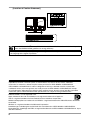
Please read PRECAUTIONS, this User’s Manual and Setup Guide
(separate volume) carefully to familiarize yourself with safe and effective usage.
• How to Setup
Please read the Setup Guide (separate volume)
• The latest User's Manual is available for download from our site:
http://www.eizo.com
[Location of Caution Statement]
As an ENERGY STAR® Partner, EIZO NANAO CORPORATION has determined that this product
meets the ENERGY STAR guidelines for energy efficiency.
Product specifications may vary depending on the region. Confirm the specifications in the manual written
in the language of the region of purchase.
Copyright© 2008 EIZO NANAO CORPORATION All rights reserved. No part of this manual may be
reproduced, stored in a retrieval system, or transmitted, in any form or by any means, electronic,
mechanical, or otherwise, without the prior written permission of EIZO NANAO CORPORATION.
EIZO NANAO CORPORATION is under no obligation to hold any submitted material or information
confidential unless prior arrangements are made pursuant to EIZO NANAO CORPORATION's receipt
of said information. Although every effort has been made to ensure that this manual provides up-to-date
information, please note that EIZO monitor specifications are subject to change without notice.
ENERGY STAR is a U.S. registered mark.
Apple, Macintosh, Mac OS and ColorSync are registered trademarks of Apple Inc.
VGA is a registered trademark of International Business Machines Corporation.
DPMS and DisplayPort are trademarks and VESA is a registered trademark of Video Electronics Standards
Association.
Windows is a registered trademark of Microsoft Corporation.
PowerManager, ColorNavigator and UniColor Pro are trademarks of EIZO NANAO CORPORATION.
ScreenManager, ColorEdge and EIZO are registered trademarks of EIZO NANAO CORPORATION in Japan
and other countries.
Notice for this Monitor
Notice for this monitor
• Aside from creating documents, viewing multimedia content, and other general purposes, this product is
also suited to applications such as graphics creation and digital photo processing, where accurate color
reproduction is a priority.
• This product has been adjusted specifically for use in the region to which it was originally shipped. If the
product is used outside the region, it may not operate as specified in the specifications.
• This product may not be covered by warranty for uses other than those described in this manual.
• The specifications noted in this manual are only applicable for power cords and signal cables specified by
us.
• Use optional products manufactured or specified by us with this product.
• As it takes about 30 minutes for the performance of electrical parts to stabilize, adjust the monitor 30
minutes or more after the monitor power has been turned on.
• In order to suppress the luminosity change by long-term use and to maintain the stable luminosity, use of a
monitor in lower brightness is recommended.
• When the screen image is changed after displaying the same image for extended periods of time, an
afterimage may appear. Use the screen saver or timer to avoid displaying the same image for extended
periods of time.
• Periodic cleaning is recommended to keep the monitor looking new and to prolong its operation lifetime.
(Refer to "Cleaning" on the next page.)
• The LCD panel is manufactured using high-precision technology. However, note that the appearance of any
missing pixels or lit pixels does not indicate damage to the LCD monitor.
Percentage of effective pixels : 99.9994% or higher.
• The backlight of the LCD panel has a fixed life span. When the screen becomes dark or begins to flicker,
please contact your dealer.
• Do not press on the panel or edge of the frame strongly, as this may result in the display malfunction, such
as the interference patterns, etc. If pressure is continually applied to the LCD panel, it may deteriorate or
damage your LCD panel. (If the pressure marks remain on the LCD panel, leave the monitor with a white or
black screen. The symptom may disappear.)
• Do not scratch or press on the panel with any sharp objects, such as a pencil or pen as this may result in
damage to the panel. Do not attempt to brush with tissues as this may scratch the LCD panel.
• When the monitor is cold and brought into a room or the room temperature goes up quickly, dew
condensation may occur inside and outside the monitor. In that case, do not turn the monitor on and wait
until dew condensation disappears, otherwise it may cause some damages to the monitor.
Notice for this Monitor
Cleaning
NOTE
•Never use thinner, benzene, alcohol, abrasive cleaners, or other strong solvents, as these may cause
damage to the cabinet or LCD panel.
[LCD Panel]
•The LCD surface can be cleaned with a soft cloth, such as cotton or lens paper.
•If necessary, stubborn stains can be removed by using the provided ScreenCleaner, or moistening
part of a cloth with water to enhance its cleaning power.
[Cabinet]
•To remove stains, wipe the cabinet with a soft, lightly moistened cloth using a mild detergent. Do
not spray wax or cleaner directly into the cabinet. (For details, refer to the manual of the PC.)
To use the monitor comfortably
•An excessively dark or bright screen may affect your eyes. Adjust the brightness of the monitor
according to the environmental conditions.
•Staring at the monitor for a long time tires your eyes. Take a 10-minute rest every hour.
Table of Contents
. ............................................................ 1
4.Troubleshooting................................................ 23
Notice for this monitor........................................... 3
5. Reference.......................................................... 26
Cover
Cleaning.................................................................. 4
5-1. Attaching an Arm............................................... 26
To use the monitor comfortably............................ 4
5-2. Connecting Two PCs to the Monitor................ 27
Table of Contents................................................... 5
5-3. Utilizing USB (Universal Serial Bus)................ 28
1. Introduction......................................................... 6
5-4. Setting Range of Frequency............................. 29
1-1. Features............................................................... 6
5-5. Specifications.................................................... 30
1-2. Controls and Functions...................................... 7
1-3. Utility Disk............................................................ 8
5-6. Glossary............................................................. 34
6. APPENDIX/ANHANG/ANNEXE........................ 36
1-4. Basic Operation and Functions......................... 9
Basic Operation...................................................... 9
About TCO'03........................................................ 38
Functions.............................................................. 10
FCC Declaration of Conformity........................... 39
2. Adjusting Screen.............................................. 11
2-1. Setting Screen Resolution.................................11
Compatible Resolutions/Frequencies.................11
Hinweise zur Auswahl des richtigen
Schwenkarms für Ihren Monitor /
Hinweis zur Ergonomie........................................ 40
Setting Resolution................................................ 12
2-2. Displaying Screen Correctly (Analog Input Only)........................................ 13
2-3. Adjusting Color................................................. 16
Simple Adjustment (Switching FineContrast Mode).......................... 16
Advanced Adjustments [Adjustment menu]...... 17
2-4. Displaying Lower Resolutions......................... 19
3. Setting Monitor................................................. 20
3-1. Setting Power Saving ...................................... 20
Analog Input......................................................... 20
Digital Input........................................................... 20
3-2. Using Off Timer................................................. 21
3-3. Locking Button Operation................................ 21
3-4. Setting Power Indicator.................................... 22
3-5. Changing Orientation........................................ 22
3-6. Setting EIZO Logo Display............................... 22
1. Introduction
1. Introduction
Thank you very much for choosing an EIZO Color Monitor.
1-1. Features
•24.1" wide format LCD
•Wide color gamut of 97% of Adobe RGB
•Applicable to HDCP
•Applicable to DisplayPort (8-bit only, audio unsupported)
•Dual inputs compliant (DVI-I x 1 and DisplayPort x 1)
•[Horizontal scanning frequency]
Analog: 24 - 130 kHz
Digital: 26 - 78 kHz
[Vertical scanning frequency]
Analog: 47.5 - 120Hz Digital: 23.75 - 63Hz (VGA TEXT: 69 - 71Hz)
[Resolution] 1920 dots x 1200 lines
•Frame Synchronous mode supported (23.75 - 31.5Hz, 47.5 - 63Hz)
•The Portrait/Landscape display capability (rotate 90 degrees clockwise)
•The provided "ColorNavigator" calibration software enables you to calibrate monitor
characteristics and generate ICC profiles (for Windows) and Apple ColorSync profiles (for
Macintosh) (refer to "1-3. Utility Disk" on page 8)
•Color Vision Deficiency Simulation Software "UniColor Pro" supported
(This software can be downloaded from http://www.eizo.com)
•Smoothing function incorporated for the adjustment of an enlarged image
•FineContrast modes, to select the most suitable mode for screen display (refer to "2-3. Adjusting
Color" on page 16)
•Height adjustable stand
•Auto EcoView function incorporate
•Attaching the "Adjustment Certificate" to describe the grayscale and uniformity characteristics of
the monitor individually
•Monitor hood attached
Tips
•This monitor supports the Portrait/Landscape display. This function allows you to change the
orientation of the Adjustment menu when using the monitor screen in vertical display position.
(Refer to "3-5. Changing Orientation" on page 22.)
•For using the monitor with “Portrait” position, the graphics board supporting portrait display is
required. When using the monitor with "Portrait" position, the setting needs to be changed
depending on the graphics board used in your PC.
1. Introduction
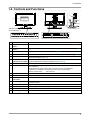
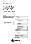
1-2. Controls and Functions
14
17
16
15
Adjustment menu
(ScreenManager®*)
1
2
3
4
5
6
7
8
9
10 11
12
13
1
Sensor
Detects ambient brightness. Auto EcoView function
2
Adjustment Lock
button
This function locks the buttons to retain the status adjusted or set once. (page 21)
3
Input Signal Selection
button
Switches input signals for display when two PCs are connected to the monitor. (page
27)
4
Mode button
Allows you to switch the FineContrast mode. (page 16)
5
Auto button
Performs the function to adjust the screen automatically. (analog input only) (page 13)
6
Enter button
Displays the Adjustment menu, determines an item on the menu screen, and
saves values adjusted. (page 9)
7
Control buttons
(Left, Down, Up, Right)
Chooses an adjustment item or increases/decreases adjusted values for
advanced adjustments using the Adjustment menu. (page 9)
8
Power button
Turns the power on or off.
9
Power indicator
Indicates monitor’s operation status.
Blue: Operating
Flashing blue (2 times for each): When the timer is set for ColorNavigator,
notifies that a recalibration is required (for CAL mode or EMU mode).
Orange: Power saving
Off: Power off
10
Main Power switch
Turns the main power on or off.
11
Power connector
Connects the power cord.
12
Input signal
connectors
DVI-I Connector x 1 / DisplayPort Connector x 1
13
USB port (Up)
Connects the USB cable to use the software that needs USB connection, or to use
USB Hub function.
14
USB port (Down)
Connects a peripheral USB device.
15
Stand
Used to adjust the height and angle of the monitor screen.
16
Security lock slot
Complies with Kensington’s MicroSaver security system.
17
Cable holder
Covers the monitor cables.
*ScreenManager
®
is an EIZO’s nickname of the Adjustment menu.
1. Introduction
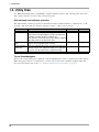
1-3. Utility Disk
An "EIZO LCD Utility Disk" (CD-ROM) is supplied with the monitor. The following table shows the
disk contents and the overview of the software programs.
Disk contents and software overview
The disk includes software programs for adjustment and User’s Manual. Refer to "Readme.txt" or the
"read me" file on the disk for software startup procedures or file access procedures.
Item
Overview
A “Readme.txt” or “read me” file
ColorNavigator
An application software for calibrating monitor
characteristics and generating ICC profiles (for Windows)
and Apple ColorSync profiles (for Macintosh).
(A PC must be connected to the monitor with the supplied
USB cable.) Refer to the descriotion later.
Screen Adjustment Monitor pattern display software used when adjusting the
Utility
image of the analog input signal manually.
Screen adjustment Used when adjusting the image of the analog signal input
pattern files
manually. If the Screen Adjustment Utility is not applicable
to your PC, use this pattern files to adjust the image.
User’s Manual (PDF file)
For Windows For Macintosh
√
√
√
√
√
–
√
–
√
√
To use ColorNavigator
Refer to the corresponding User's Manual on the CD-ROM disk in order to install and use the software.
When using this software, you will need to connect a PC to the monitor with the supplied USB cable.
For more information refer to the "5-3. Utilizing USB (Universal Serial Bus)" (page 28).
1. Introduction
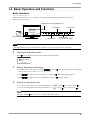
1-4. Basic Operation and Functions
Basic Operation
Adjustment menu allows you to adjust screen performance though the main menu and select a
FineContrast mode easily.
Adjustment menu (ScreenManager®)
Enter button
FineContrast Menu
Mode button
Power button
Control buttons
(Left, Down, Up, Right)
Note
•The Adjustment menu and the FineContrast menu cannot be displayed at the same time.
1
Entering the Adjustment menu
Press
2
once to display the main menu of the Adjustment menu.
Making Adjustments and Settings
1.Select the desired sub menu icon using
and press
the sub menu, refer to the “Functions” (page 10)).
3
2.Use
to select the desired setting icon and press
3.Use
to make all required adjustments and press
. The sub menu appears. (Regarding
. The setting menu appears.
save the settings.
Exiting the Adjustment menu
1.To return to the main menu, select the <Return> icon
2.To exit the Adjustment menu, select the <Exit> icon
or press
or press
twice, followed by
twice, followed by
.
.
Tips
•Double clicking
at any time also exits the Adjustment menu.
1. Introduction
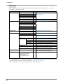
Functions
The following table shows all the Adjustment menu's adjustment and setting menus. "*" indicates
adjustments of analog input only.
Main menu
Screen
Color (Custom)*1
PowerManager
Others
Sub menu
Clock
Phase
Position
Resolution
Range Adjustment
Smoothing
Signal Filter
Brightness
Temperature
Gamma
Saturation
Hue
Gain
6 Colors
Reset
On
Off
Screen Size
Border Intensity
Input Signal
Off Timer
Menu Settings
Menu Size
Menu Position
Menu Off Timer
Translucent
Orientation
Auto EcoView
Power Indicator
Information
Language
Reset
Information
English, German, French,
Spanish, Italian, Swedish,
Chinese(Simplified),
Chinese(Traditional) and
Japanese
Reference
*
*
*
*
*
*
“2-2. Displaying Screen Correctly (Analog Input
Only)” (page 13)
“2-4. Displaying Lower Resolutions” (page 19)
Set when a noise appears on the screen.
“2-3. Adjusting Color” (page 16)
“3-1. Setting Power Saving” (page 20)
“2-4. Displaying Lower Resolutions” (page 19)
“5-2. Connecting Two PCs to the Monitor” (page
27)
“3-2. Using Off Timer” (page 21)
Change the size of the menu.
Adjust the menu position.
Set the menu displaying time.
Set the transparency of the background.
Set the orientation of the Adjustment menu.
Set automatic brightness adjustment.
Make non-light for blue lighting when the screen
is displayed. ( Power Indicator Setting. )
Return to the factory Default settings.
Review the Adjustment menu's settings, model
name, serial number and usage time.*2
Select the Adjustment menu's language.
*1The adjustable functions on the <Color> menu depend on the selected FineContrast mode (page 16). The above table shows
the sub menus when the "Custom" mode is selected (See "2-3. Adjusting Color" (page 16)).
*2Due to the inspection on the factory, the usage time may not "0 hour" at shipping.
10
2. Adjusting Screen
2. Adjusting Screen
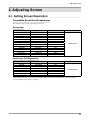
2-1. Setting Screen Resolution
Compatible Resolutions/Frequencies
The monitor supports the following resolutions.
Analog Input
Resolution
Display Mode
Frequency
Dot Clock
640×480
640×480
720×400
800×600
832×624
1024×768
1152×864
1152×870
1280×960
1280×960
1280×1024
1600×1200
1680×1050*1
1920×1200*1 *2
VGA, VESA
Macintosh
VGA TEXT
VESA
Macintosh
VESA
VESA
Macintosh
VESA
Macintosh
VESA
VESA
VESA CVT
VESA CVT, VESA CVT RB
~85Hz
67Hz
70Hz
~85Hz
75Hz
~85Hz
75Hz
75Hz
60Hz
75Hz
~85Hz
~75Hz
60Hz
60Hz
204MHz (Max.)
Digital Input (DVI/DisplayPort)
Resolution
Display Mode
Frequency
Dot Clock
640×480
720×480
800×600
1024×768
1280×960
1600×1200
1680×1050*1
1920×1200*1 *2
VGA
VGA TEXT
VESA
VESA
VESA
VESA
VESA CVT, VESA CVT RB
VESA CVT RB
60Hz
70Hz
60Hz
60Hz
60Hz
60Hz
60Hz
60Hz
164.5MHz (Max.)
*1
When displaying the wide format input signal, a graphics board in conformance with VESA CVT standard is required.
*2
Recommended resolution (Set this resolution).
11
2. Adjusting Screen
Setting Resolution
Windows Vista
1.
2.
3.
4.
Right-click the mouse anywhere on the desktop except for icons.
From the displayed menu, click "Personalize".
On the "Personalization" window, click "Display Settings".
On the "Display Settings" dialog, select the "Monitor" tab and select desired resolution in the
"Resolution" field.
5. Click the "OK" button.
6. When a confirmation dialog is displayed, click "Yes".
Windows XP
1. Right-click the mouse anywhere on the desktop except for icons.
2. From the displayed menu, click "Properties".
3. When the "Display Properties" dialog is displayed, click the "Settings" tab and select desired
resolution for "Screen resolution" under "Display".
4. Click the "OK" button to close the dialog.
Mac OS X
1. Select "System Preferences" from the Apple menu.
2. When the "System Preferences" dialog is displayed, click "Displays" for "Hardware".
3. On the displayed dialog, select the "Display" tab and select desired resolution in the "Resolutions"
field.
4. Your selection will be reflected immediately. When you are satisfied with the selected resolution,
close the window.
12
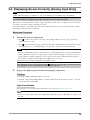
2. Adjusting Screen
2-2. Displaying Screen Correctly (Analog Input Only)
Note
•Allow the LCD monitor to stabilize for at least 30 minutes before making image adjustments.
The monitor displays the digital input image correctly based on its pre-setting data.
The monitor screen adjustment is used to suppress flickering of the screen or adjust screen position and
screen size correctly according to the PC to be used.
To use the monitor comfortably, adjust the screen when the monitor is set up for the first time or when
the settings of the PC in use are updated.
Adjustment Procedure
1
Perform the auto size adjustment.
1.Press
on the control panel. A message “Your setting will be lost, if you press again now”
appears for five seconds.
2.Press
again while the message is displayed. The Auto Adjustment function begins (showing a
running status icon) to adjust flickering, screen position, and screen size automatically.
Note
•The Auto Adjustment function is intended for use on the Macintosh and on AT-compatible PC
running Windows. It may not work properly in either of the following cases. It does not work
properly when an image is displayed only on a part of the screen (command prompt window,
for example) or when a black background (wallpaper, etc.) is in use.
•It cannot work correctly using with some graphics cards.
If the appropriate screen cannot be made by using , adjust the screen through the following procedures.
If the appropriate screen can be made, proceed to 5. Range Adjustment .
2
Prepare the display pattern for the analog display adjustment.
Windows
1.Load the “EIZO LCD Utility Disk” to your PC.
2.Start the “Screen Adjustment Utility” from the startup menu. If it cannot be started, open the
screen adjustment pattern files.
Other than Windows
Download the "Screen adjustment pattern files" from our site: http://www.eizo.com.
Tips
•For how to open and use the screen adjustment pattern files, refer to “Readme.txt” or the “read
me” file.
13
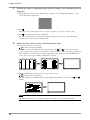
2. Adjusting Screen
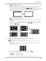
3
Perform the auto size adjustment again with the analog screen adjustment pattern
displayed.
1.Display Pattern 1 in full screen on the monitor using the “Screen Adjustment Utility” or the
screen adjustment pattern files.
2.Press .
A message “Your setting will be lost, if you press again now” appears for five seconds.
3.Press
again while the message is displayed.
The Auto Adjustment function begins (showing a running status icon) to adjust flickering,
screen position, and screen size automatically.
4
Adjust by using <Screen> menu in the Adjustment menu
(1)Vertical bars appear on the screen
Use the <Clock> adjustment.
and
of the Control buttons. Select the <Clock> and eliminate the vertical bars by using
Do not continuously press the Control buttons, as the adjustment value will change quickly and
make it difficult to locate the most suitable adjustment point. If the horizontal flickering, blur
or bars appear, proceed to <Phase> adjustment as follows.
(2) Horizontal flickering, blurring or bars appear on the screen.
Use the <Phase> adjustment. Select the <Phase> and eliminate the horizontal flickering, blurring or bars by using
buttons.
Note
•Horizontal bars may not completely disappear from the screen depending on the PC.
14
and
2. Adjusting Screen
(3) The screen position is incorrect.
Use the <Position> adjustment.
The correct displayed position of the monitor is decided because the number and the position of
the pixels are fixed. The <Position> adjustment moves the image to the correct position.
and . If vertical bars of distortion
Select <Position> and adjust the position by using , ,
appear after finishing the <Position> adjustment, return to <Clock> adjustment and repeat the
previously explained adjustment procedure. ("Clock" => "Phase" => "Position")
(4) Screen image is smaller or larger than the actual screen images.
Use the <Resolution> adjustment.
Adjustment is needed when the input signal resolution and the resolution now being displayed
are different. Select <Resolution> and confirm if the resolution now being displayed is the same as the input
resolution. If it is not, adjust the vertical resolution using
and
and adjust the horizontal
and .
resolution using
Extra image is displayed due to excessive dots.
A part of image is cut due to short dots.
5
Adjust the output signal range (Dynamic Range) of the signal.
Use the <Range Adjustment> of <Screen> menu.
This controls the level of output signal range to display the whole color gradation (256 colors).
[Procedure]
1.Display Pattern 2 in full screen on the monitor using the “Screen Adjustment Utility” or the
screen adjustment pattern files.
2.Choose <Range Adjustment> from the <Screen> menu, and press .
A message “Your setting will be lost it you press AUTO button” appears.
3.Press
while the message is displayed. Color gradation is adjusted automatically.
4.Close the Pattern 2. When using the “Screen Adjustment Utility”, close the program.
15
2. Adjusting Screen
2-3. Adjusting Color
Simple Adjustment (Switching FineContrast Mode)
This function allows you to select the best display mode for monitor brightness, etc.
To Select FineContrast Mode
Directly pressing
allows you to select the best suited mode for screen display from 4 FineContrast
modes; Custom, sRGB, EMU and CAL. Color settings each mode can be adjusted by using the <Color>
menu of the Adjustment menu.
Press
to exit the menu.
->Custom -> sRGB -> EMU -> CAL
Tips
•The Adjustment menu and the FineContrast menu cannot be displayed at the same time.
Power button
Mode button
Enter button
FineContrast Menu
[EX.]Custom
Control buttons
Current Mode
Settings status
of Brightness,
Temperature and
Gamma
FineContrast Mode
Selectable FineContrast modes are as follows.
Mode
Custom
sRGB
EMU
CAL
Purpose
Available for the color settings according to your preference.
Suitable for color matching with sRGB compatible peripherals.
Displays the screen adjusted by calibration software.
Color Adjustment of the Mode Settings
<Brightness>, <Temperature> and <Gamma> settings can be adjusted on the FineContrast menu. Select
the desired function icon with
and adjust with
Control buttons. (Setting(s) of <Temperature>
and/or <Gamma> is defined as standard default in some modes.)
Note
•"CAL" mode and "EMU" mode can be adjusted only by Calibration Software "ColorNavigator".
16
2. Adjusting Screen
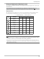
Advanced Adjustments [Adjustment menu]
Color settings of each FineContrast mode can be adjusted and saved by using the <Color> menu of the
Adjustment menu.
In the analog input, perform the "Range Adjustment" before making the color adjustments. During color
adjustments, the FineContrast mode cannot be changed. Select the mode in advance by using
Adjustment Items
The adjustable items and displayed icons on the <Color> menu depend on the selected FineContrast
mode. Regarding the adjustment items, refer to the “Adjustment Contents” on the next page.
Icons
" √ ": Settable/Adjustable " - ": Fixed at the factory
Functions
Custom
FineContrast Mode
sRGB
EMU
CAL
Brightness*
√
√
-
-
Temperature*
√
-
-
-
Gamma*
√
-
-
-
Saturation
√
-
-
-
Hue
√
-
-
-
Gain
√
-
-
-
6 Colors
√
-
-
-
Reset
√
√
-
-
* These settings can be also adjusted on the FineContrast menu.
Note
•Allow the LCD monitor to stabilize for at least 30 minutes before making image adjustments. (Allow
the monitor to warm up for at least 30 minutes before making adjustments.)
•The values shown in percentages represent the current level within the specific adjustment. They are
available only as a reference tool. (To create a uniform white or black screen, the percentages for each
will probably not be the same.)
17
2. Adjusting Screen
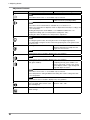
Adjustment Contents
Menu
Brightness
Function Descriptions
To set the brightness of the screen
Adjustable range
0~100%
Tips
Temperature
•The values shown in the “%” are available only as reference.
To set the color temperature
4000K~10000K
in 500 K increments (including 9300 K)
Tips
•The values shown in the Kelvin are available only as a reference tool.
•While color temperature is adjusted, <Gain> is adjusted automatically according to the
color temperature.
•Setting the temperature under 4000 K or over 10000 K invalidates the color
temperature setting. (The color temperature's setting turns "Off".)
Gamma
•Setting the <Gain> invalidates the <Temperature> adjustment.
To set the gamma value
1.8~2.6
Tips
Saturation
•If setting the gamma value, the using the monitor in the digital signal input is
recommended. If using the monitor in the analog input signal, set the gamma value
from 1.8 to 2.2.
To change the saturation
-100~100
Setting the minimum level (-100) turns the
image to the monochrome.
Note
Hue
•This function does not enable to display every color gradation.
To change the flesh color, etc.
-100~100
Note
Gain
•This function does not enable to display every color gradation.
To change each color
0~100%
(red, green and blue)
By adjusting the red, green and blue color
tones for each mode, custom colors can be
defined. Display a white or gray background
image and adjust the <Gain>.
Tips
•The values shown in the “%” are available only as reference.
•The <Temperature> setting invalidates this setting. The <Gain> setting varies with
color temperature.
Note
6 colors
Reset
18
•This function does not enable to display every color gradation.
To adjust <Saturation> and <Hue> in
Hue: -100 ~ 100
each color (Red, Yellow, Green, Cyan, Saturation: -100 ~ 100
Blue and Magenta)
To return the color settings to the
default settings
Select the <Reset>.
2. Adjusting Screen
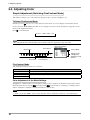
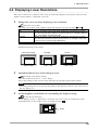
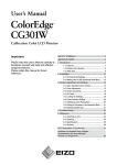
2-4. Displaying Lower Resolutions
The lower resolutions are enlarged to full screen automatically. Using the <Screen Size> function in the
<Others> menu enables to change the screen size.
1
Enlarge the screen size when displaying a low resolution.
Select the <Screen Size>.
Select the <Screen Size> in the <Others> menu and select the screen size by using
Mode
Function
Full
Enlarged
Normal
and
.
Displays the picture on the screen in full, irrespective of the picture's resolution.
Since the verticalresolution and the horizontal resolution are enlarged at different
rates, some images may appeardistorted.
Displays the picture on the screen in full, irrespective of the picture's resolution.
Since the vertical resolution and horizontal resolution are enlarged at same rates,
some horizontal or vertical image maydisappear.
Displays the picture at the actual Screen resolution.
Example: Displaying 1280 x 1024
Full (Default Setting)
(1920 × 1200)
2
Enlarged
(1500 × 1200)
Normal
(1280 × 1024)
Smooth the blurred texts of the enlarged screen.
Switch the <Smoothing> setting.
Select the suitable level from 1 - 5 (Soft - Sharp).
Select <Smoothing> in the <Screen> menu and adjust by using the right and left switches.
Note
•Smoothing setting may not be required depending on the display resolution. (You cannot choose
the smoothing icon.)
3
Set the brightness of the black area surrounding the displayed image.
Set the <Border Intensity>.
In the "Enlarge" mode or "Full Screen" mode, the outer area (border) is usually black. Select
.
<BorderIntensity> in the <Others> menu and adjust by using
Border
19
3. Setting Monitor
3. Setting Monitor
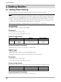
3-1. Setting Power Saving
The <PowerManager> menu in the Adjustment menu enables to set the power saving.
Note
•Do your part to conserve energy, turn off the monitor when you are finished using it. Turning off the
main power switch or unplugging the power cord completely shuts off power supply to the monitor.
•Devices connected to the USB port (upstream and downstream) work when the monitor is in power
saving mode or when the power button of the monitor is Off. Therefore, power consumption of the
monitor varies with connected devices even in the power saving mode.
•When using ColorNavigator, turning of the power saving function is recommended.
Analog Input
This monitor complies with the "VESA DPMS".
[Procedure]
1.Set the PC's power saving settings.
2.Select "On" from the <PowerManager> menu.
[Power Saving System]
Power saving
PC
Monitor
Power Indicator
ON
STAND-BY
SUSPEND
OFF
Operation
Blue
Power saving
Orange
[Power Resumption Procedure]
Operate the mouse or keyboard to return to a normal screen.
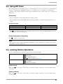
Digital Input
•DVI: This monitor complies with the DVI DMPM standard.
•DisplayPort: This monitor complies with the DisplayPort Standard V1.1a.
[Procedure]
1.Set the PC's power saving settings.
2.Select "On" from the <PowerManager> menu.
[Power Saving System]
The monitor enters the power saving mode in five seconds in connection with the PC setting.
PC
Monitor
Power Indicator
ON
Power saving
Operation
Power saving
Blue
Orange
[Power Resumption Procedure]
Operate the mouse or keyboard to return to a normal screen.
20
3. Setting Monitor
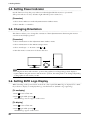
3-2. Using Off Timer
The off timer function causes the monitor to automatically enter a power off state after a predetermined
amount of time has lapsed. With this function you can reduce power consumption for unused time
regardless of the setting of the PC. Use this function when the monitor screen is left on for a long period
without use.
[Procedure]
1.Select <Off Timer> in the Adjustment menu <Others> menu.
2.Select "Enable and touch the Right and Left directing switches to adjust the operating time (1 to 23
hours).
[Off Timer System]
PC
Monitor
Operating time (1H - 23H)
Last 15 min. in operating time
Operating time expired
*1
ON
Advance Notice *1
Power OFF
Power Indicator
Blue
Blue Flashing
OFF
When
is pressed during the advance notice period, the monitor continues to operate for additional 90 minutes. Extension
of operation time can be set without limitation.
[Power Resumption Procedure]
Press
to return a normal screen.
Note
•The off timer function works while the PowerManager is active, but there is no advance notice before
the monitor's power is turned off.
3-3. Locking Button Operation
Use the "Adjustment Lock" function to prevent any accidental changes.
Buttons that can be locked
Buttons that cannot be locked
•
(Enter button) / Adjustments/settings using
•
(Mode button)
•
(Auto Adjustment button)
•
•
+
EIZO Logo display setup (page 22)
(Input Signal Selection button)
•
(Power button)
•
(Adjustment Lock button)
[How to lock]
Hold down
are locked.
for 2 seconds or more. The power indicator lights orange for 1 second, and the settings
[How to unlock]
Hold down
for 2 seconds or more. The power indicator lights orange for 1 second, and the settings
are unlocked. 21
3. Setting Monitor
3-4. Setting Power Indicator
Use the function to keep the power indicator without light while the monitor is operational.
(The power indicator is set by default to light when the power is turned on.)
[Procedure]
1.Select <Power Indicator> in the Adjustment menu <Others> menu.
2.Select "Enable" or "Disable".
3-5. Changing Orientation
This function allows you to change the orientation of the Adjustment menu when using the monitor
screen in vertical display position.
[Procedure]
1.Select <Orientation> in the Adjustment menu <Others> menu.
2.Select <Orientation> in the <Menu Settings> menu.
3.Select “Landscape” or “Portrait” with
or
.
4.Turn the monitor screen 90° in clockwise direction.
Tips
•For using the monitor with “Portrait” position, the graphics board supporting portrait display is
required. When using the monitor with "Portrait" position, the setting needs to be changed depending
on the graphics board used in your PC.
3-6. Setting EIZO Logo Display
When switching on the power button on the front control panel, the EIZO logo is displayed for a while.
If you desire to display or undisplay this logo, use this function. (Default is logo appearing.)
[To undisplay]
1.Press
to turn off the unit.
2.Press
again while pressing .
The EIZO logo does not appear on the screen.
[To display]
1.Press
to turn off the unit.
2.Press
again while pressing .
The EIZO logo appear on the screen.
22
4.Troubleshooting
4.Troubleshooting
If a problem still remains after applying the suggested remedies, contact your local dealer.
•No-picture problems : See No.1 - No.2
•Imaging problems : See No.3 - No.14
•Other problems : See No.15 - No.18
•USB problems : See No.19
Problems
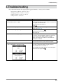
1.No picture
•Power indicator does not light.
Possible cause and remedy
•Check whether the power cord is connected correctly. If
the problem persists, turn off the monitor, and then turn
it on again a few minutes later.
•Turn the main power switch on.
•Press
.
•Power indicator is lighting blue.
•Set each adjusting value in <Brightness> or <Gain> to
higher level (page 18).
•Power indicator is lighting orange.
•Switch the input signal with
.
•Operate the mouse or keyboard.
•Turn on the PC.
•Power indicator is flashing orange.
2.The message below appears.
•This message appears when no signal is input.
(This is displayed for about 40 seconds)
•There is a problem in the device that uses DisplayPort
connection. Solve the problem, and turn off the main
power of the monitor, and then turn it on again.
Refer to the manual of the device connected to the
DisplayPort for details.
This message appears when the signal is not input
correctly even when the monitor functions properly.
•The message shown left may appear, because some
PCs do not output the signal soon after power-on.
•Check whether the PC is turned on.
•Check whether the signal cable is connected properly.
•Switch the input signal with
.
23
4.Troubleshooting
Problems
Possible cause and remedy
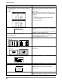
•The message below shows that the input signal is out of
the specified frequency range. (Such signal frequency is
displayed in red.)
•Check whether the signal setting of your PC matches
the resolution and the vertical frequency settings for the
monitor (page 11).
Example:
•Reboot the PC.
•Select an appropriate display mode using the graphics
board’s utility. Refer to the manual of the graphics board
for details.
fD:Dot Clock
(Displayed only when the digital signal inputs)
fH:Horizontal Frequency
fV: Vertical Frequency
3.Display position is incorrect.
•Adjust image position so that it is displayed properly
within the display area using the <Position> adjustment
(page 15).
•If the problem persists, use the graphics board’s utility if
available to change the display position.
4.Screen image displayed is smaller or larger than the
actual screen image.
•Adjust the resolution using <Resolution> so that the
input signal resolution equals the resolution in the
resolution adjustment menu (page 15).
5.Vertical bars appear on the screen or a part of the image
is flickering.
•Adjust using <Clock> (page 14).
6.The characters and images have several vertical bars on
their right side.
•Adjust the characters and images using the
<Signal Filter>.
7.Whole screen is flickering or blurring.
•Adjust using <Phase> (page 14).
8.Characters are blurred.
•Adjust using <Smoothing> (page 19).
9.Upper part of the screen is distorted as shown below.
•This is caused when both composite sync (X-OR)
signal and separate vertical sync signal are input
simultaneously. Select either composite signal or
separate signal
10.The screen is too bright or too dark.
•Adjust <Brightness>. (The LCD monitor backlight has a
fixed life span. When the screen becomes dark or begins
to flicker, contact your local dealer.)
24
4.Troubleshooting
Problems
11.Afterimages appear.
Possible cause and remedy
•Use a screen saver or off timer function for a long-time
image display.
•Afterimages are particular to LCD monitors. Avoid
displaying the same image for a long time.
12.Green/red/blue/white dots or defective dots remain on
the screen.
•This is due to LCD panel characteristics and is not a
failure.
13.Interference patterns or fingerprints remain on the
screen.
•Leave the monitor with a white screen or a black screen.
The symptom may disappear.
14.Noise appears on the screen.
•When entering the signals of analog input, select 1 to
4 in <Signal Filter> from the <Screen> menu to change
the mode.
•When entering the signals of HDCP system, the normal
images may not be displayed immediately.
15.The <Smoothing> icon on the Adjustment menu
<Screen> cannot be selected.
•Smoothing setting may not be required depending
on the display resolution. (You cannot choose the
smoothing icon.)
•<Smoothing> is disabled when the screen is displayed
in the following resolutions.
•1920 × 1200
• 800 × 600, selecting [Enlarged] duirng <Screen
Size>
• 960 × 600, selecting [Enlarged] duirng <Screen
Size>
•1600 × 1200, selecting [Enlarged] duirng <Screen
Size>
•Select [Normal] during <Screen Size>.
16.The Main menu of Adjustment menu does not start.
•Check for Adjustment Lock function (page 21).
17.The FineContrast mode is not displayed.
•Check for Adjustment Lock function (page 21).
18.
• (Auto Adjustment function) does not function when
digital signal is input.
does not function.
•Check for Adjustment Lock function (page 21).
19.The monitor connected with the USB cable is not
detected. / USB devices connected to the monitor does
not work.
•This function does not work correctly with some graphics
boards.
•Check that the USB cable is correctly connected.
•Check the downstream ports by connecting the
peripherals to other downstream ports. If the problem is
solved by doing this, contact an EIZO dealer. (For details,
refer to the manual of the PC.)
•Reboot the PC
•If the peripheral devices work correctly when the PC and
peripheral devices are connected directly, please contact
your local dealer.
•Check that the PC and OS are USB compliant. (For
verification of USB support, consult the manufacturer of
each system.)
•Check the PC's BIOS setting for USB when using
windows. (For details, refer to the manual of the PC.)
25
5. Reference
5. Reference
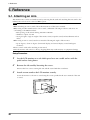
5-1. Attaching an Arm
The LCD monitor can be used with an arm by removing the tilt stand and attaching the arm stand to the
LCD monitor. Use an arm or stand of EIZO option.
Note
•When attaching an arm or stand, follow the instructions of their user’s manual.
•When using another manufacturer’s arm or stand, confirm the following in advance and select one
conforming to the VESA standard.
-Hole spacing on the arm mounting: 100 mm x 100 mm
-Thickness of plate: 2.6 mm
-Strong enough to support weight of the monitor unit (except the stand) and attachments such as
cables.
•When using an arm or stand, attach it to meet the following tilt angles of the monitor.
-Up 45 degrees, down 45 degrees (horizontal display, and vertical display rotated 90 degrees
clockwise)
•Please connect cables after attaching an arm stand.
•Since the monitor and arm are so heavy, dropping them may result in injury or equipment damage.
Setup Procedure
1
2
Lay the LCD monitor on a soft cloth spread over on a stable surface with the
panel surface facing down.
Remove the tilt stand by loosening the screws.
Unscrew the four screws securing the unit and the satand with the screwdriver.
3
Attach an arm stand to the LCD monitor securely.
Secure the monitor to the arm or stand using the screws specified in the user's manual of the arm
or stand.
26
5. Reference
5-2. Connecting Two PCs to the Monitor
Two PCs can be connected to the monitor through the DVI-I connector and DisplayPort connector on
the back of the monitor.
Connection examples
DVI-I
DisplayPort
PC 1
(Ex.1) Digital
DVI
D-Sub
(Ex.2) Analog mini 15
pin
PC 2
Signal Cable
(FD-C39 enclosed)
Signal Cable
(PP200 optional)
Signal Cable
(FD-C16 enclosed)
DisplayPort
Digital
Selecting input signal
Switch the input signal with . Input signal switches each time
is pressed. When the signal is
switched, the active signal type (DVI digital, DVI analog or DisplayPort) appears at the top right corner
of the screen.
Input Signal Selection button
The monitor recognizes the connector through which PC signals are input. When either PC is turned off
or enters the power-saving mode, the monitor automatically displays signals of another PC.
Input signal setting
Auto
Manual
Performance
If one of the PC turned off or became to power saving mode, the other
signal is automatically displayed.
The monitor detects only the PC’s signals currently displaying automatically.
Select the active input by pressing .
Note
•When "Auto" is selected for <Input Signal>, the power saving mode of the monitor activates only if
both PCs are in power saving mode.
27
5. Reference
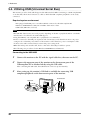
5-3. Utilizing USB (Universal Serial Bus)
This monitor provides a hub which supports the USB standard. When connecting to a USB compliant PC
or another hub, the monitor functions as a hub to which the USB compliant peripherals can be easily
connected.
Required system environment
•PC equipped with USB ports or another USB hub connected to the USB compliant PC
•Windows 2000/XP/Vista // Mac OS 9.2.2/Mac OS X 10.2 or later
•USB Cable (MD-C93, enclosed)
Note
•The USB hub function may not work properly depending on the PC or peripherals. Please consult the
manufacturer of each device about the USB support.
•Using the USB Rev. 2.0 compatible PC or peripherals is recommended.
•Devices connected to the USB port (upstream and downstream) work when the monitor is in power
saving mode or when the power button of the monitor is Off. Therefore, power consumption of the
monitor varies with connected devices even in the power saving mode.
•When the main power switch is Off, device connected to the USB port will not operate.
•The followings are procedures for the Windows 2000/XP/Vista and Mac OS.
Connecting to the USB HUB
1
2
Connect the monitor to the PC with the signal cable first, then turn on the PC.
Connect the upstream port of the monitor to the downstream port of the
USBcompliant PC or another hub by using the USB cable.
After connecting the USB cable, the USB function can be set up automatically.
3
After setting up, the monitor's USB hub is available for connecting USB
compliantperipherals to the downstream ports of the monitor.
Downstream
Upstream
28
5. Reference
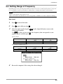
5-4. Setting Range of Frequency
Depending upon your operating environment, it may be necessary to set the frequency that corresponds
to your graphics board. If you install it for the first time or change environment, set the monitor.
NOTE
•Refer to the manual of the graphics board.
•These environment described below can be set regardless of whether or not the computer is running.
How to set
1
Press
to turn off the unit.
2
Press
again while pressing
3
.
Select the input signal using the
in the <Signal Selection> menu at the
center of the monitor.
to select (or just confirm) the frequency that corresponds to your
Use
.
graphics board, and then press
[Analog Input]
Setting
Normal
Wide
Horizontal scanning frequency
(kHz)
24~94
24~130
Vertical scanning frequency
(Hz)
47~86
47~120
Horizontal scanning frequency
(kHz)
31~76
26~78
Vertical scanning frequency
(Hz)
59~61
23~63
[Digital Input (DVI/DisplayPort)]
Setting
Normal
Wide
4
Restart the computer if the settings have been changed.
29
5. Reference
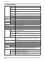
5-5. Specifications
LCD Panel
Size
61 cm (24.1 inch)
Surface
treatment
Hard Coating
Surface
hardness
3H
Response
Time
Approx. 12 ms
Viewing
Angle
Horizontal : 178°, Vertical : 178°(CR: 10 or more)
Dot Pitch
0.270 mm
Horizontal Scan Analog
Frequency
Digital
24 ~ 130 kHz (Automatic)
Vertical Scan
Frequency
Analog
47.5 ~ 120 Hz (Automatic)
Digital
23.75 ~ 63 Hz (VGA TEXT: 69 ~ 71 Hz)
Resolution
Dot Clock
(Max.)
26 ~ 78 kHz
1920 dots x 1200 lines
Analog
204 MHz
Digital
164.5 MHz
Display Colors
16.77 million colors (max.)
Recommended Brightness
120 cd/m2 or less (with color temperature of between 5000K to 6500K)
Display Area
518.4 mm (H) × 324.0 mm (V) (20.4" (H) x 12.8" (V))
Power Supply
100-120/200-240 VAC±10%, 50/60 Hz, 1.05 A/0.5 A
Power
Consumptionl
Screen
Display On
105 W (with USB load)
95 W (without USB load)
Power Saving 1.5 W or less (for DVI-I single signal input without USB load, [Input Signal]:
Mode
“Manual”)
Power Button 1 W or less (without USB load)
off
Main Power
switch off
Input Signal Connector
0W
DVI-I connector (Applicable to HDCP) x 1
DisplayPort connector (Complies with Standard V1.1a, applicable to
HDCP) x 1
Analog Input Signal (Sync)
Separate, TTL, Positive/Negative
Composite, TTL, Positive/Negative
Analog Input Signal (Video)
0.7 Vp-p / 75 ohms, Positive
Input Signal (Digital) (DVI)
TMDS (Single Link)
Signal
registration
Analog
45 (Factory preset: 27)
Digital
10 (Factory preset: 0)
Plug & Play
Analog / Digital (DVI-I) : VESA DDC 2B / EDID structure 1.3
Digital (DisplayPort) : VESA DisplayPort / EDID structure 1.4
Dimensions
with stand
566 mm (W) x 456 ~ 538 mm (H) x 230 mm (D)
(22.3"(W) x 18" ~ 21.2" (H) x 9.1"(D))
without stand 566 mm (W) x 367 mm (H) x 85 mm (D)
(22.3"(W) x 14.4" (H) x 3.35"(D))
with hood
30
571 mm (W) x 462 ~ 544 mm (H) x 347.6 mm (D)
(22.5"(W) x 18.2" ~ 21.4" (H) x 13.7"(D))
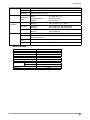
5. Reference
Weight
with stand
Approx. 10.7 kg (23.6 lbs.)
without stand Approx. 7.1 kg (15.7 lbs.)
with hood
Approx. 11.5 kg (25.4 lbs.)
Movable range
Height
adjustable
stand
Tilt:
Swivel:
Adjustable height:
Rotation:
40° Up, 0° Down
35° Right, 35° Left
82 mm (3.23 inch)
90° (clockwise)
Environment
Conditions
Temperature
Operating:
Storage:
0°C ~ 35°C (32°F ~ 95°F)
-20°C ~ 60°C (-4°F ~ 140°F)
Humidity
Operating:
Storage:
30% to 80% R.H. Non-condensing
30% to 80% R.H. Non-condensing
Pressure
Operating:
Storage:
700 to 1060 hPa.
200 to 1060 hPa.
standard
USB Specification Revision 2.0
USB port
Upstream port x 1
Downstream port x 2
USB
Communication 480 Mbps (high), 12 Mbps (full), 1.5 Mbps (low)
Speed
Power Supply Downstream: 500 mA for each (max.)
Default settings
Brightness
Smoothing
Temperature
FineContrast Mode
PowerManager
Screen Size
Input Signal
Off Timer
Menu Settings
Menu Size
Menu Off Timer
Auto EcoView
Language
15%
3
6500K
Custom
On
Full
Auto
Disable
Normal
45 sec
Disable
English
31
5. Reference
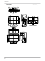
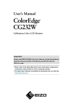
Dimensions
uinit: mm (inch)
56.3(2.22)
85(3.35)
190(7.5)
35°
35°
SWIVEL
287.5(11.3)
TILT
40°
566(22.3)
520.4(20.5)
399.5(15.7)
30.4(1.2)
230(9.1)
347.6(13.7)
236(9.3)
229(9.0)
151(5.9)
355(14.0)
462~544(18.2~21.4)
373(14.7)
183.5(7.2)
571(22.5)
45.6
(1.8)
398.5(15.7)
32
100(3.9)
133.5(5.3)
82(3.23)
272.5(10.7)
367(14.4)
456~538(18~21.2)
326(12.8)
133.5(5.3)
233(9.2)
100(3.9)
233(9.2)
5. Reference
Pin Assignment
•DVI-I Connector
1 2 3 4 5 6 7 8
9 10 11 12 13 14 15 16
17 18 19 20 21 22 23 24
C1
C2
C3 C4
C5
Pin No.
Signal
Pin No.
Signal
Pin No.
Signal
1
2
3
4
5
TMDS Data 2TMDS Data 2+
TMDS Data2/4 Shield
NC*
NC*
11
12
13
14
15
21
22
23
24
C1
NC*
TMDS Clock shield
TMDS Clock+
TMDS ClockAnalog Red
6
7
8
9
DDC Clock (SCL)
DDC Data (SDA)
Analog Vertical Sync
TMDSData1-
16
17
18
19
TMDS Data1/3 Shield
NC*
NC*
+5V Power
Ground (return for +5V,
Hsync and Vsync)
Hot Plug Detect
TMDS Data0TMDS Data0+
TMDS Data0/5 Shield
C2
C3
C4
C5
Analog Green
Analog Blue
Analog Horizontal Sync
Analog Ground(analog
R,G,&B return)
10
TMDS Data1+
20
NC*
(*NC: No Connection)
•DisplayPort Connector
19 17 15 13 11 9 7 5 3 1
20 18 16 14 12 10 8 6 4 2
Pin No.
Signal
Pin No.
Signal
Pin No.
Signal
1
ML Lane3-
8
Ground
15
AUX CH+
2
Ground
9
ML Lane1+
16
Ground
3
ML Lane3+
10
ML Lane0-
17
AUX CH-
4
ML Lane2-
11
Ground
18
Hot Plug Detect
5
Ground
12
ML Lane0+
19
Return
6
ML Lane2+
13
CONFIG1
20
DP PWR
7
ML Lane1-
14
CONFIG2
•USB Port
Upstream
Downstream
Series B
Connector
Series A
Connector
No.
Signal
Remarks
1
2
3
4
VCC
- Data
+ Data
Ground
Cable power
Serial data
Serial data
Cable Ground
33
5. Reference
5-6. Glossary
Clock
With the analog input signal display, the analog signal is converted to a digital signal by the LCD
circuitry. To convert the signal correctly, the LCD monitor needs to produce the same number clock
pulse as the dot clock of the graphics system. When the clock pulse is not correctly set, some vertical
bars of distortion are displayed on the screen.
DisplayPort
VESA provides the digital interface standard for the digital display device. DisplayPort can transfer the
video signal up to 16 bits for each channel of RGB, and the audio signal too. (This monitor supports
the 8-bit video signal only and not audio signal.)
DVI (Digital Visual Interface)
A digital flat panel interface. DVI can transmit digital data from the PC directly without loss with the
signal transition method "TMDS". There are two kinds of DVI connectors. One is DVI-D connector
for digital signal input only. The other is DVI-I connector for both digital and analog signal inputs.
DVI DMPM (DVI Digital Monitor Power Management)
The Power management system for the digital interface. The "Monitor ON" status (operation mode)
and the "Active Off" status (power-saving mode) are indispensable for the DVI-DMPM as the
monitor's power mode.
Gain Adjustment
Adjusts each color parameter for red, green and blue. The color of the LCD monitor is displayed
through the color filter of the LCD panel. Red, green and blue are the three primary colors. The colors
on the monitor are displayed by combining these three colors. The color tone can change by adjusting
the illumination amount passed through each color's filter.
Gamma
Generally, the relationship that the light intensity values of a monitor change nonlinearly to the input
signal level is called "Gamma Characteristic". On the monitor, low gamma values display the whitish
images and high gamma values display the high contrast images.
HDCP (High-bandwidth Digital Contents Protection)
Digital signal coding system developed to copy-protect the digital contents, such as video, music, etc.
This helps to transmit the digital contents safely by coding the digital contents sent via DVI terminal
on the output side and decoding them on the input side.
Any digital contents cannot be reproduced if both of the equipments on the output and input sides are
not applicable to HDCP system.
Phase
The phase adjustment decides the sampling timing point for converting the analog input signal to a
digital signal. Adjusting the phase after the clock adjustment will produce a clear screen.
Range Adjustment
The Range Adjustment controls the level of output signal range to display the whole color gradation.
34
5. Reference
Resolution
The LCD panel consists of a fixed number of pixel elements which are illuminated to form the screen
image. The display panel of this monitor consists of 1920 horizontal pixels and 1200 vertical pixels.
At a resolution of 1920 x 1200 , images are displayed as a full screen(1:1).
sRGB (Standard RGB)
"International Standard for Red, Green, and Blue color space" A color space was defined with the aim
of the color matching between applications and hardware devices, such as monitors, scanners, printers
and digital cameras. As a standard default space, sRGB allows Internet users to closely match colors.
Temperature
Color Temperature is a method to measure the white color tone, generally indicated in degrees Kelvin.
At high temperatures the white tone appears somewhat blue, while at lower temperatures it appears
somewhat red. Computer monitors generally give best performance at high temperature settings.
5000 K: Slightly reddish white (usually used in print industry)
6500 K: White called daylight color (suited for web browsing)
9300 K: Slightly bluish white (usually used for television)
TMDS (Transition Minimized Differential Signaling)
A signal transition method for the digital interface.
VESA DPMS
(Video Electronics Standards Association - Display Power Management
Signaling)
The acronym VESA stands for "Video Electronics Standards Association", and DPMS stands for
"Display Power Management Signaling". DPMS is a communication standard that PCs and graphics
boards use to implement power savings on the monitor side.
35
6. APPENDIX/ANHANG/ANNEXE
6. APPENDIX/ANHANG/ANNEXE
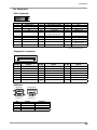
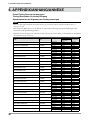
Preset Timing Chart for Analog input
Timing-Übersichten für Analog Eingang
Synchronisation des Signaux pour Analog numerique
NOTE
•Based on the signal diagram shown below factory presets have been registered in the monitor's
microprocessor.
•Der integrierte Mikroprozessor des Monitors unterstützt werkseitige Standardeinstellungen (siehe
hierzu die nachfolgenden Diagramme).
•Signaux ont été enregistrés en usine dans le microprocesseur du moniteur, conformément au diagramme
de synchronisation ci-dessous.
36
Mode
Dot Clock
MHz
VGA 640×480@60Hz
25.2 MHz
VGA TEXT 720×400@70Hz
28.3 MHz
Macintosh 832×624@75Hz
57.3 MHz
Macintosh 1280×960@75Hz
126.2 MHz
VESA 640×480@72Hz
31.5 MHz
VESA 640×480@75Hz
31.5 MHz
VESA 640×480@85Hz
36.0 MHz
VESA 800×600@56Hz
36.0 MHz
VESA 800×600@60Hz
40.0 MHz
VESA 800×600@72Hz
50.0 MHz
VESA 800×600@75Hz
49.5 MHz
VESA 800×600@85Hz
56.3 MHz
VESA 1024×768@60Hz
65.0 MHz
VESA 1024×768@70Hz
75.0 MHz
VESA 1024×768@75Hz
78.8 MHz
VESA 1024×768@85Hz
94.5 MHz
VESA 1152×864@75Hz
108.0 MHz
VESA 1280×960@60Hz
108.0 MHz
VESA 1280×1024@60Hz
108.0 MHz
VESA 1280×1024@75Hz
135.0 MHz
VESA 1600×1200@60Hz
162.0 MHz
VESA 1600×1200@65Hz
175.0 MHz
VESA 1600×1200@70Hz
189.0 MHz
VESA 1600×1200@75Hz
202.5 MHz
VESA CVT 1680 × 1050@60Hz
146.3 MHz
Horizontal
Vertical
Horizontal
Vertical
Horizontal
Vertical
Horizontal
Vertical
Horizontal
Vertical
Horizontal
Vertical
Horizontal
Vertical
Horizontal
Vertical
Horizontal
Vertical
Horizontal
Vertical
Horizontal
Vertical
Horizontal
Vertical
Horizontal
Vertical
Horizontal
Vertical
Horizontal
Vertical
Horizontal
Vertical
Horizontal
Vertical
Horizontal
Vertical
Horizontal
Vertical
Horizontal
Vertical
Horizontal
Vertical
Horizontal
Vertical
Horizontal
Vertical
Horizontal
Vertical
Horizontal
Vertical
Frequencies
Horizontal:kHz
Vertical:Hz
31.47
59.94
31.47
70.09
49.72
74.55
74.76
74.76
37.86
72.81
37.50
75.00
43.27
85.01
35.16
56.25
37.88
60.32
48.08
72.19
46.88
75.00
53.67
85.06
48.36
60.00
56.48
70.07
60.02
75.03
68.68
85.00
67.50
75.00
60.00
60.00
63.98
60.02
79.98
75.03
75.00
60.00
81.30
65.00
87.50
70.00
93.75
75.00
65.29
59.95
Sync Polarity
Negative
Negative
Negative
Positive
Negative
Negative
Positive
Positive
Negative
Negative
Negative
Negative
Negative
Negative
Positive
Positive
Positive
Positive
Positive
Positive
Positive
Positive
Positive
Positive
Negative
Negative
Negative
Negative
Positive
Positive
Positive
Positive
Positive
Positive
Positive
Positive
Positive
Positive
Positive
Positive
Positive
Positive
Positive
Positive
Positive
Positive
Positive
Positive
Negative
Positive
6. APPENDIX/ANHANG/ANNEXE
Mode
Dot Clock
MHz
VESA CVT 1920 × 1200@60Hz
193.25 MHz
VESA CVT RB 1920×1200 60Hz
154.00 MHz
Horizontal
Vertical
Horizontal
Vertical
Frequencies
Horizontal:kHz
Vertical:Hz
74.56
59.89
74.04
59.95
Sync Polarity
Negative
Positive
Positive
Negative
37
Congratulations!
The display you have just purchased carries the TCO’03 Displays label. This
means that your display is designed, manufactured and tested according to
some of the strictest quality and environmental requirements in the world.
This makes for a high performance product, designed with the user in focus
that also minimizes the Impact on our natural environment.
Some of the features of the TCO’03 Display requirements:
Ergonomics
● Good visual ergonomics and image quality in order to improve the working environment for the user
and to reduce sight and strain problems. Important parameters are luminance, contrast, resolution,
reflectance, colour rendition and image stability.
Energy
● Energy-saving mode after a certain time - beneficial both for the user and environment
● Electrical safety
Emissions
● Electromagnetic fields
● Noise emissions
Ecology
● The products must be prepared for recycling and the manufacturer must have a certified environmental
management system such as EMAS or ISO 14000
● Restrictions on
● chlorinated and brominated flame retardants and polymers
● heavy metals such as cadmium, mercury and lead.
The requirements includes in this label have been developed by TCO Development in co-operation with scientists,
experts, users as well as manufacturers all over the world. Since the end of the 1980s TCO has been involved in
influencing the development of IT equipment in a more user-friendly direction. Our labeling system with displays
in 1992 and is now requested by users and IT-manufacturers all over the world.
For more information, please visit
www.tcodevelopment.com
38
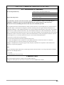
For U.S.A. , Canada, etc. (rated 100-120 Vac) Only
FCC Declaration of Conformity
We, the Responsible Party
EIZO NANAO TECHNOLOGIES INC.
5710 Warland Drive, Cypress, CA 90630
Phone: (562) 431-5011
declare that the product
Trade name: EIZO
Model: ColorEdge CG242W
is in conformity with Part 15 of the FCC Rules. Operation of this product is subject to the following two
conditions: (1) this device may not cause harmful interference, and (2) this device must accept any
interference received, including interference that may cause undesired operation.
This equipment has been tested and found to comply with the limits for a Class B digital device, pursuant to Part 15
of the FCC Rules. These limits are designed to provide reasonable protection against harmful interference in a
residential installation. This equipment generates, uses, and can radiate radio frequency energy and, if not installed
and used in accordance with the instructions, may cause harmful interference to radio communications. However,
there is no guarantee that interference will not occur in a particular installation. If this equipment does cause harmful
interference to radio or television reception, which can be determined by turning the equipment off and on, the user
is encouraged to try to correct the interference by one or more of the following measures.
*
*
*
*
Reorient or relocate the receiving antenna.
Increase the separation between the equipment and receiver.
Connect the equipment into an outlet on a circuit different from that to which the receiver is connected.
Consult the dealer or an experienced radio/TV technician for help.
Changes or modifications not expressly approved by the party responsible for compliance could void the user’s
authority to operate the equipment.
Note
Use the attached specified cable below or EIZO signal cable with this monitor so as to keep interference within the
limits of a Class B digital device.
- AC Cord
- Shielded Signal Cable (Enclosed)
Canadian Notice
This Class B digital apparatus complies with Canadian ICES-003.
Cet appareil numérique de le classe B est comforme à la norme NMB-003 du Canada.
39
Hinweise zur Auswahl des richtigen Schwenkarms für Ihren Monitor
Dieser Monitor ist für Bildschirmarbeitsplätze vorgesehen. Wenn nicht der zum Standardzubehör gehörige
Schwenkarm verwendet wird, muss statt dessen ein geeigneter anderer Schwenkarm installiert werden. Bei der
Auswahl des Schwenkarms sind die nachstehenden Hinweise zu berücksichtigen:
Der Standfuß muß den nachfolgenden Anforderungen entsprechen:
a)Der Standfuß muß eine ausreichende mechanische Stabilität zur Aufnahme des Gewichtes vom Bildschirmgerät
und des spezifizierten Zubehörs besitzen. Das Gewicht des Bildschirmgerätes und des Zubehörs sind in der
zugehörenden Bedienungsanleitung angegeben.
b)Die Befestigung des Standfusses muß derart erfolgen, daß die oberste Zeile der Bildschirmanzeige nicht höher
als die Augenhöhe eines Benutzers in sitzender Position ist.
c)Im Fall eines stehenden Benutzers muß die Befestigung des Bildschirmgerätes derart erfolgen, daß die Höhe der
Bildschirmmitte über dem Boden zwischen 135 – 150 cm beträgt.
d)Der Standfuß muß die Möglichkeit zur Neigung des Bildschirmgerätes besitzen (max. vorwärts: 5°, min. nach
hinten ≥ 5°).
e)Der Standfuß muß die Möglichkeit zur Drehung des Bildschirmgerätes besitzen (max. ±180°). Der maximale
Kraftaufwand dafür muß weniger als 100 N betragen.
f)Der Standfuß muß in der Stellung verharren, in die er manuell bewegt wurde.
g)Der Glanzgrad des Standfusses muß weniger als 20 Glanzeinheiten betragen (seidenmatt).
h)Der Standfuß mit Bildschirmgerät muß bei einer Neigung von bis zu 10° aus der normalen aufrechten Position
kippsicher sein.
Hinweis zur Ergonomie :
Dieser Monitor erfüllt die Anforderungen an die Ergonomie nach EK1-ITB2000 mit dem Videosignal, 1920×
1200, Digital Eingang und mindestens 60,0 Hz Bildwiederholfrequenz, non interlaced. Weiterhin wird aus
ergonomischen Gründen empfohlen, die Grundfarbe Blau nicht auf dunklem Untergrund zu verwenden (schlechte
Erkennbarkeit, Augenbelastung bei zu geringem Zeichenkontrast.)
„Maschinenlärminformations-Verordnung 3. GPSGV:
Der höchste Schalldruckpegel beträgt 70 dB(A) oder weniger gemäss EN ISO 7779“
40