1
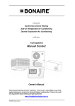
Owner’s Manual
Using your
Domestic Ducted Evaporative Air Conditioning
with the
Climate Control
Celair Profile Series
Operating, Setup & Maintenance
www.celair.com.au
Please keep this important manual in a safe place. It is the owner’s responsibility to ensure that
regular maintenance is carried out on this Evaporative Air Conditioner. Failure to do so will void all
guarantees beyond statutory and legal requirements.
TEK600 SERIES CONTROL
PROFILE SERIES OWNER’S MANUAL
Contents
INTRODUCTION ............................................................................................................. 4
DUCTED EVAPORATIVE AIR CONDITIONER ...................................................................... 5
INTRODUCTION .................................................................................................................... 5
Exhaust ........................................................................................................................................... 5
Dialflo .............................................................................................................................................. 6
Optional Dump Valve ...................................................................................................................... 6
OPERATING THE CONTROLS .......................................................................................... 7
Manual Operation............................................................................................................................ 7
Fan Only...................................................................................................................................... 7
Fan & Pump ................................................................................................................................ 7
Turning off Unit............................................................................................................................ 7
Ventilation ....................................................................................................................................... 7
Automatic Operation ....................................................................................................................... 7
Timer Function ................................................................................................................................ 8
Timer ON..................................................................................................................................... 8
Timer OFF ................................................................................................................................... 8
UNIT MAINTENANCE ...................................................................................................... 9
FILTER PADS....................................................................................................................... 9
UNIT W ATER RESERVOIR ..................................................................................................... 9
WATER LEVEL / FLOAT VALVE .............................................................................................. 9
MOTOR AND FAN ................................................................................................................. 9
ELECTRICAL ........................................................................................................................ 9
BLEED OFF ......................................................................................................................... 9
PUMP ................................................................................................................................. 9
WATER DISTRIBUTION ....................................................................................................... 10
PROBLEM SOLVING ........................................................................................................... 10
CONTROL SETUP & COMMISSIONING............................................................................ 11
SAFETY ............................................................................................................................ 11
BEFORE COMMENCING ...................................................................................................... 11
Packaging ..................................................................................................................................... 11
Is the control system correct? ....................................................................................................... 11
CONTROL LOCATION.......................................................................................................... 12
INSTALLING THE CONTROL ................................................................................................. 12
TEK 600 W IRING DIAGRAM................................................................................................ 13
CLIMATE CONTROL – SETUP OPTIONS ................................................................................ 14
Options.......................................................................................................................................... 14
Parameter Settings Table ............................................................................................................. 15
Entering the Parameter Setting Mode .......................................................................................... 15
TEK600 SERIES CONTROL
Page 2
PROFILE SERIES OWNER’S MANUAL
Contents
Setting the dump delay ................................................................................................................. 15
Setting the Pre-cool. ..................................................................................................................... 16
Setting the Dump Interval Cycles.................................................................................................. 16
Setting the Pre-fill (2 + 4 hour light on and the Auto light flashing). ............................................. 16
Reviewing Programmed Settings.................................................................................................. 17
Setting the Thermostat Control Minimum / Maximum speed settings. ......................................... 18
HAND OVER ...................................................................................................................... 18
COMMISSIONING CHECK LIST ............................................................................................. 19
General ......................................................................................................................................... 19
Unit - Ducted Evaporative Air Conditioner .................................................................................... 19
Ductwork ....................................................................................................................................... 19
Site ................................................................................................................................................ 19
Customer Hand Over .................................................................................................................... 19
WARRANTY ................................................................................................................ 20
SERVICE .................................................................................................................... 23
TEK600 SERIES CONTROL
Page 3
PROFILE SERIES OWNER’S MANUAL
Introduction
INTRODUCTION
CONGRATULATIONS ON YOUR CHOICE
We are delighted you have chosen an air conditioning product from Climate Technologies
to cool your home. It’s an air conditioner we’re very proud of. Designed and made in
Australia by Climate Technologies, 100% Australian owned company, it contains the latest
advances in Fresh Air Conditioning technology in a stylish, attractive cabinet.
TEK600 SERIES CONTROL
Page 4
PROFILE SERIES OWNER’S MANUAL
Ducted Evaporative Air Conditioner
DUCTED EVAPOR AT IVE AIR COND ITIONER
INTRODUCTION
The Ducted Evaporative Air Conditioner is engineered to meet the rigors of our harsh
Australian environment. Operated and maintained in accordance with this manual, it will
provide you with years of quiet, cool and environmentally friendly operation. Please take
the time to read this manual.
The principal of your unit is to introduce fresh air, which is washed through the filter pads to
provided cool fresh air. The air is exhausted taking with it any heat loadings on the home.
Exhaust
It is essential for successful operation of evaporative air-conditioning that there are
sufficient exhaust openings in the area to be ventilated. Open doors and windows will
usually provide this.
The minimum exhaust opening should be as per the table guide set out below. It is
recommended that ceiling vents or exhaust fans be used where there is any doubt about
there being sufficient exhaust area available. Ceiling exhaust fans or ceiling vents should
have a capacity equivalent to that of the air conditioner.
MODEL
TEK600 SERIES CONTROL
MINIMUM
EXHAUST AREA
Small Cabinet
0.80 m²
Medium Cabinet
1.43 m²
Large Cabinet
1.75 m²
Page 5
PROFILE SERIES OWNER’S MANUAL
Ducted Evaporative Air Conditioner
Dialflo
BLEED OFF
All evaporative air conditioners need some water bleed-off to
prevent build-up of mineral deposits in the system. The
correct setting of the bleed rate will ultimately govern the life of
the unit.
With normal town water supply, in good water quality areas,
bleed rate should be adjusted so that the discharge is not less
than 10 litres per hour subject to unit size. Increased water
hardness may require a higher bleed rate and increased
maintenance.
Setting the BLEED OFF Rate.
To set the bleed rate locate the patented DIALFLO
externally on one of the corner posts. Rotate the BLEED
knob clockwise for more flow and anti clockwise.
Note: Hold the distribution knob (Filler) while setting the
bleed rate as the distribution flow rate may go out of
adjustment.
It is recommended that the bleed water is plumbed away
to waste in accordance with local and state plumbing
requirements.
Setting the Water Distribution Flow Rate
To set the water distribution flow rate to the filter pads,
rotate filter knob anti-clockwise for more water and
clockwise for less water. To control bleed-off rate rotate
bleed dial clockwise for more water and anti-clockwise
for less water.
Note: Hold the bleed knob while setting the distribution
rate as the bleed rate may go out of adjustment.
Optional Dump Valve
If a dump valve is fitted and dumping cycles are
activated, bleed off may not be required. Drainage from
the dump valve needs also to be plumbed away in
accordance with local and state plumbing requirements.
It’s Climate Technologies recommendation that the drain
from the dump valve is plumbed to waste.
TEK600 SERIES CONTROL
Page 6
PROFILE SERIES OWNER’S MANUAL
Controls Operation
OPER ATIN G TH E CONTR OL S
Your ducted evaporative air conditioner has been supplied with the 4-button Climate control.
The Climate controller has two modes of operation, MANUAL or AUTOMATIC. In addition it
has a TIMER, which will operate in either mode.
Manual Operation
Fan Only
Pressing the FAN button once will turn on the green fanlight and will start the fan only.
The variable speed dial will vary the speed of the fan.
Fan & Pump
Pressing the COOL button once will turn on the green cool light and will start the fan and
pump. The variable speed dial will vary the speed of the fan.
*NOTE: When the COOL button is pressed there may be a two or three minute delay in
start up if PRE-FILL, or PRE-COOL has been selected in the set up of the controller.
This is indicated by a flashing green light next to the COOL button or AUTO button. For
more information on these features contact your nearest Climate Technologies dealer or
from place of purchase.
Turning off Unit
To switch the unit off, press the button that has the green light. This light will then go out
to indicate the unit is off.
Ventilation
On days of high humidity, your unit may operate more effectively in ventilation mode.
To start the FAN ONLY press the fan button.
Use the dial
to control the comfort level required (speed of the fan).
Automatic Operation
•
To select AUTOMATIC mode press the AUTO button. The green light will be on to
indicate that the unit is in the auto mode.
•
To select the desired comfort level use the dial
. The dial does not control the
speed of the fan this is done automatically by the controller.
Note: The comfort level is individual to each situation and location. Some trial and
error may be required to set the dial to your desired comfort level; a good
starting point is to have the dial set at the Nine o'clock position. Once the unit
has been set, the fan speed and pump are controlled automatically. The unit
can be left and will cycle on and off to keep the area being cooled to the set
comfort level.
•
Around the edge of the dial there is a marking, for more cooling turn the dial
clockwise to where the marking increases in size. If the room temperature is too cold
turn the dial anti-clockwise for less cooling (a warmer comfort setting).
TEK600 SERIES CONTROL
Page 7
PROFILE SERIES OWNER’S MANUAL
Controls Operation
Timer Function
The timer function operates either in Automatic or Manual modes and is designed to switch
the unit ON or OFF in a pre-set period (two, four or eight hours).
Note: Once the time function has activated or deactivated the unit, it will remain in this mode
until another selection has been made at the wall control.
Timer ON
•
To switch the unit ON in a pre-set time, firstly select FAN, COOL, or AUTO. Adjust the
dial
to your selected position. Press the same button again to turn the unit back to
the off mode.
•
Select the desired time to switch the unit back on in two, four, or eight hours by
pressing the TIMER button until your selected time appears which is indicated by the
green light.
•
The option that has been selected will begin to flash rapidly. This is indicating to the
user that the mode selected will start in the selected time.
•
If the owner wants to start the unit instead of waiting for the timer, press the button that
the green light is flashing once then press the same button once more to start the unit.
This can be indicated by the green light coming on near the button selected.
*NOTE: Repeated TIMER button presses selects the desired time and also disables
the timer. The green lights near the two, four, or eight-hour time selections must be
illuminated else the timer is in the disabled mode.
Timer OFF
•
The timer off mode will switch off the unit in the selected two, four, or eight hours.
•
While the unit is running press the TIMER button to select the two, four, or eight-hour
time option.
•
Once the time mode has been selected the unit will turn off in the selected time period
and remain in the off mode until pressing one of the function buttons (FAN, COOL, OR
AUTO) to restart it.
*NOTE: Repeated TIMER button presses selects the desired time and also disables
the timer. The green lights near the two, four, or eight-hour time selections must be
illuminated else the timer is in the disabled mode.
TEK600 SERIES CONTROL
Page 8
PROFILE SERIES OWNER’S MANUAL
Unit Maintenance
UNIT M AINT EN ANCE
Warning: Before commencing any maintenance work on your unit, isolate the power
at the supply (Fuse Box).
Note:
It is essential that your evaporative air conditioner be maintained in accordance
with this manual. Failure to do so will affect the life of the product and reduce the
level of efficiency.
FILTER PADS
Visually check CELDEK pads for damage or blockage. Hose down pads from both sides to
remove any build up of salts, dust and pollen. In dusty areas more regular cleaning is
recommended. Check the water distributor, making sure it is clear and free from blockage.
Failure to do so may lead to uneven water distribution and therefore less efficient
operation. Do not hose Celdek with high pressure.
UNIT WATER RESERVOIR
It is important to keep the water tank clean and free from sediment and algae growth. To
clean the tank, use a soft brush or similar. Wipe all surfaces in the tank while it is full of
water (DO NOT FORGET THE PUMP STRAINER). Turn off the water inlet to the unit (an
Isolation Valve should be fitted to the water inlet before the Float Valve). Drain the tank by
removing the standpipe. It may be necessary to repeat this procedure if the tank is very
dirty.
SAFETY: Wet roofs are dangerous – Take Care When draining unit reservoir.
WATER LEVEL / FLOAT VALVE
The water level should be set at nominal 65-70mm from the top of the overflow. The float
valve is a mechanical type and is factory set. If it requires adjustment keep bends tight. If
the valve is leaking the seal may require cleaning or replacing. Turn the water off. Remove
the split pin and then float arm. Remove piston and clean or turn seal. Flush system and
replace piston, float arm and split pin.
Note: Water supply line to float valve must be flushed before connecting.
Note: Some discharge from the overflow may be experienced after shut down due to
water draining back from the Celdek pads. Adjust float valve.
MOTOR AND FAN
Check that the fan spins freely and that there is no build up on the blades.
ELECTRICAL
No general maintenance is required to the electrical system.
A Qualified Electrician should only carry out electrical connections and maintenance.
BLEED OFF
The bleed rate should be checked to ensure it is adequate and that there is no build up of
mineral deposits in or on your air conditioner. White deposits indicate high mineral content
and the Bleed Rate should be increased. If it is at maximum and the deposits are still
forming, then more regular maintenance is required.
PUMP
Check the pump spins freely and that the strainer is clean.
TEK600 SERIES CONTROL
Page 9
PROFILE SERIES OWNER’S MANUAL
Unit Maintenance
WATER DISTRIBUTION
Check the water distribution system for blockage. Check the delivery tube for kinks or
holes. Check that the clamps are secure and in place.
PROBLEM SOLVING
PROBLEM
Unit fails to start
Pump fails to start
PROBABLE CAUSE
REMEDY
a
b
c
d
Black - out
Tripped Circuit Breaker
Blown Fuse
Electrical Fault
a
b
c
d
a
Pump Seized
a
b
Pump Burnt Out
b
a
Float Valve Leaking
a
Water leaking from
overflow
b
Drain from Celdek Pads
b
Water Droplets in air
stream
a
b
c
a
b
c
a
Loose Delivery Tube
Break in tubing
Pump Delivers Excessive
Water to Pads
Inadequate Exhaust
b
a
b
Outside humidity high
Dirty Filters
Dry Filters
b
a
b
c
Dialflo not set correctly
c
a
Unit located near odour
source
a
a
Excessive humidity
Inadequate Cooling
Unpleasant Odour
High Mineral Content
Rapid formation of
white deposits on
pads
Wait
Reset
Replace
Call Climate Technologies
Service Provider
Call Climate Technologies
Service Provider
Call Climate Technologies
Service Provider
Check adjustment or replace
seal
Adjust Ball Valve level
Check and tighten
Replace as necessary
Adjust the Dialflo to reduce
the flow
Provide more open area to
exhaust stale air
Turn pump off may assist.
Clean
Check water delivery
system. Adjust dialflo if
necessary.
Adjust dialflo so that the
pads have even saturation.
Remove source
Bleed off should be set at
maximum. More regular
maintenance may be
required. Dump valve may
be required for cyclic
dumping
THIS TROUBLE SHOOTING GUIDE IS A REFERENCE ONLY.
FOR SERVICE OR WARRANTY REQUIREMENTS PLEASE RING
YOUR NEAREST CLIMATE TECHNOLOGIES SERVICE PROVIDER
TEK600 SERIES CONTROL
Page 10
PROFILE SERIES OWNER’S MANUAL
Controls Setup & Commissioning
CONTROL SETUP & COMM ISSIONING
Your evaporative air conditioner has been supplied with the Climate Low voltage control
featuring basic control options and thermostat, timed delayed starting and stopping, and
dump valve features.
This low voltage controls are connected to the air conditioner control box via a 20-metre low
voltage loom.
NOTE:
Do not run the low voltage loom in long parallel runs with 240V mains
cables.
Keep the low voltage loom 200mm away from any long runs of mains
wiring.
Cross over mains wiring at right angles.
Do not use existing access holes in wall cavities where 240V mains
wiring exist. Drill a new access hole 200mm from the existing hole.
SAFETY
•
Switch OFF the power and unplug the unit before touching any wiring or performing
any work.
•
A QUALIFIED ELECTRICIAN must carry out all 240-volt electrical work.
BEFORE COMMENCING
Packaging
Upon delivery, check that there is no damage to the unit. Any damage should be reported
to your nearest Climate Technologies sales outlet.
Is the control system correct?
Check the customer order to ensure that you have all the correct equipment for installation.
TEK600 SERIES CONTROL
Page 11
PROFILE SERIES OWNER’S MANUAL
Controls Setup & Commissioning
CONTROL LOCATION
Climate wall control:
•
Locate the wall switch on an internal wall of a conditioned room of the home,
approximately 1.5M above the floor level, in an easily accessible location as agreed
with the customer.
•
The controller must not be installed into areas where a ceiling register may blow cold
air over the control, or installed near appliances that may generate heat. This will
cause erratic thermostat operation.
•
The control is supplied with a 20-metre connection loom to the air conditioner.
The thermostatic wall-mounted controllers should be in a
conditioned room in a location that enables correct thermostat
operation. Ensure that the location is suitable for the customer.
INSTALLING THE CONTROL
The wall controller is provided with a 20-metre loom to connect the wall control to the
control box in the unit.
Follow these instructions for best installation:
1. Connect the low voltage loom to one of the communication points in the unit control box.
Refer to wiring diagram
2. Pull the cable through to the designated point for the permanent application of the wall
control.
3. Mount the control base plate to the wall.
4. Connect the loom to the wall control and fit the control panel to the base plate.
TEK600 SERIES CONTROL
Page 12
PROFILE SERIES OWNER’S MANUAL
Controls Setup & Commissioning
TEK 600 WIRING DIAGRAM
TEK600 SERIES CONTROL
Page 13
PROFILE SERIES OWNER’S MANUAL
Controls Setup & Commissioning
CLIMATE CONTROL – SETUP OPTIONS
This controller has a number of options for the installer to set before commissioning the
unit.
Options
OPERATION
FUNCTION
This mode controls the dump valve. (If fitted).
DUMP
DELAY
PRE-COOL
The dump delay is used to set the dump valve to dump 40 seconds
after the pump is turned off or can be set to dump one hour after the
pump has turned off.
After 40 seconds or 1 hour the base is drained and left dry until the
next cycle.
The pre-cool feature is used to let the pump wet the pads for 2 minutes
before the controller turns the fan on.
This feature applies to the COOL and AUTO modes.
The pre-cool can be selected to be either on or off.
The dump interval is used to cycle the dump valve (if fitted) in 1, 2, 4,
8, 12, and 24 hour cycles. If the unit is on for long periods of time or
the water has a high mineral content a dumping interval can be set to
help maintain the unit.
DUMP
INTERVAL
PRE-FILL
When the dumping time interval has timed out, (e.g.: after 4 hours of
pump operation) the unit will shut down for 2 minutes while the dump
valve drains the water from the base.
After 2 minutes the dump valve is closed, the base fills with water and
the unit starts in the same mode that it was in before the dumping
cycle commenced.
The pre-fill mode allows the base to be filled with water (if a dump
valve has been fitted) for 1 minute before starting the pump and can be
set to the on or off mode.
TEK600 SERIES CONTROL
Page 14
PROFILE SERIES OWNER’S MANUAL
Controls Setup & Commissioning
Parameter Settings Table
The below table is a parameter chart for setting the unit.
This chart is also printed on the back of the wall switch.
Setting Installer Parameters.
Press and hold the FAN+TIMER buttons for 10 seconds, release, and press the TIMER
button once
Parameters
Dump delay
Pre-cool
Dump interval
Pre-fill
Parameter indicator
2hr light
4hr light
8hr light
2+4hr light
OFF
•
•
•
ON
• • (default)*
• • (default)*
• • (default)*
0HR
• (default)*
Parameter
setting
1HR
••
(Number of
AUTO light
flashes)
2HR
•••
4HR
••••
8HR
•••••
12HR
••••••
24HR
•••••••
* Note: the default settings in the above table are factory set.
Entering the Parameter Setting Mode
To enter and adjust the parameter setting mode follow the instructions below:
1. Start with the wall switch in the off mode.
2. Press and hold the both the FAN and TIMER buttons together for 10 seconds.
Release both buttons and press the TIMER button once.
3. The 2hr light will turn on and the AUTO light will flash. At this point the control is ready
for any settings to be entered into the wall control.
Setting the dump delay
(2 hour light on and Auto light flashing)
1. To set the dump delay to dump 40 seconds after the pump turns off, rotate the dial fully
to the minimum position and the auto light will flash once every two seconds.
2. To set the dump delay to dump 1 hour after the pump has switched off, rotate the dial
fully to the maximum position and the auto light will flash twice every two seconds.
3. Press the FAN button once to select the desired mode. (The fanlight will flash three
times to confirm the setting).
4. Press the AUTO button to go to the next setting (go to step 6) or press the TIMER button
to cancel.
TEK600 SERIES CONTROL
Page 15
PROFILE SERIES OWNER’S MANUAL
Controls Setup & Commissioning
Setting the Pre-cool.
(4 hour light on and Auto light flashing).
1. To disable the Pre-cool feature rotate the dial fully to the minimum position and the auto
light will flash once every two seconds.
2. To activate the Pre-cool feature rotate the dial fully to the maximum position and the auto
light will flash twice every two seconds.
3. Press the FAN button once to select the desired mode. (The fanlight will flash three
times to confirm the setting).
4. Press the AUTO button to go to the next setting or press the timer button to cancel.
Setting the Dump Interval Cycles
(8 hour light on and the Auto light flashing).
1. To disable the dumping cycle feature rotate the dial fully to the minimum speed position
and the auto light will flash once every two seconds.
2. To activate the one hourly dumping cycle, rotate the dial anti-clockwise until the auto
light flashes twice every two seconds.
3. To activate the two hourly dumping cycle, rotate the dial anti-clockwise until the auto light
flashes three times every two seconds.
4. To activate the four hourly dumping cycle, rotate the dial anti-clockwise until the auto
light flashes four times every two seconds.
5. To activate the eight hourly dumping cycle, rotate the dial anti-clockwise until the auto
light flashes five times every two seconds.
6. To activate the twelve hourly dumping cycle, rotate the dial anti-clockwise until the auto
light flashes six times every two seconds.
7. To activate the twenty four hourly dumping cycle, rotate the dial anti-clockwise until the
auto light flashes seven times every two seconds.
8. Press the FAN button once to select the desired mode. (The fanlight will flash three
times to confirm the setting).
9. Press the AUTO button to go to the next setting or press the TIMER button to cancel.
Setting the Pre-fill (2 + 4 hour light on and the Auto light flashing).
1. To disable the pre-fill feature rotate the dial fully to the minimum speed position and the
auto light will flash once every two seconds.
2. To activate the Pre-fill feature, rotate the dial fully to the maximum position and the auto
light will flash twice every two seconds.
3. Press the FAN button once to select the desired mode. (The fanlight will flash three
times to confirm the setting).
4. Press the TIMER button to complete the programming and to resume to normal
operation
TEK600 SERIES CONTROL
Page 16
PROFILE SERIES OWNER’S MANUAL
Controls Setup & Commissioning
Reviewing Programmed Settings.
To review the settings entered into the Climate control, enter the parameter setting mode
as explained from steps one to four on Page 15.
Once entering the parameter setting mode DO NOT ROTATE THE ADJUSTABLE DIAL.
Read the number of flashes from the AUTO light in with the two-hour light on.
1. Press the AUTO button once and the four-hour light will turn on, read the number of
flashes from the AUTO light.
2. Press the AUTO button once and the eight-hour light will turn on, read the number of
flashes from the AUTO light.
3. Press the AUTO button once and the two and four-hour lights will turn on, read the
number of flashes from the AUTO light.
If all settings are correct press the TIMER button to resume normal operation. If any
further adjustments need to be made go back to step one of the parameter settings.
Energizing the Dump Valve Solenoid to Check the Water Level.
When a dump valve is fitted, the wall control is able to operate the dump valve solenoid
and pump independent of the fan operating so that the water level can be set, and Dialflo
adjustments can be made to the filter pads and bleed off.
1. Start with the wall switch in the off mode.
2. Press and hold the both the COOL and TIMER buttons together for 10 seconds.
Release both buttons and press the TIMER button once.
3. The four-hour light will flash once every two seconds to indicate that the dump valve
solenoid has been energized and is filling the base with water. The dump valve solenoid
will remain energized for ten minutes, after ten minutes the pump will start automatically
which then the bleed off and filter pad dialflo adjustments can be made.
4. If the installer does not want to wait ten minutes before the pump starts press the AUTO
button once to start the pump immediately.
5. The four-hour light will begin to flash twice every two seconds indicating that the pump
has been started.
6. To cancel this mode and return too normal operation press the TIMER button once. If the
timer button has not been pressed the pump will run for thirty minutes before tuning itself
off.
TEK600 SERIES CONTROL
Page 17
PROFILE SERIES OWNER’S MANUAL
Controls Setup & Commissioning
Setting the Thermostat Control Minimum / Maximum speed settings.
1. Start with the wall switch in the off mode.
2. Press and hold the auto and timer buttons for ten seconds then release, after releasing
these two buttons press and release the timer button once.
3. The auto light will flash continuously and the four-hour light will flash once every two
seconds, this indicates that the unit is ready for low speed adjustment. If this does not
occur repeat steps 1 and 2.
4. Rotate the adjustable dial fully anti-clockwise and press the fan button once, the fan light
will flash three times to confirm the new setting has been entered.
5. To increase the minimum speed setting rotate the dial clockwise to a desired set point
and press the fan button to enter the new setting. (NOTE: The fan speed will not change
until the fan button has been pressed).
6. If the minimum speed needs to be increased further rotate the adjustable dial and press
the fan button to enter the new setting.
Once the minimum speed has been set press the auto button to adjust the high speed
setting (go to step 7) or press the timer button once to escape the minimum and
maximum speed setting mode and return to normal wall switch operation.
7. Once the minimum speed has been set press the auto button once and the auto light will
flash continuously and the four hour light will flash twice every two seconds, indicating
that the unit is ready for maximum speed adjustment.
8. Rotate the adjustable dial fully clock-wise and press the fan button once to enter the new
setting.
9. If the maximum speed needs to be decreased rotate the dial anti-clockwise then press
the fan button to enter the new setting.
10. If the fan speed needs to be decreased further repeat step 9.
11. Once minimum and maximum speeds have been adjusted press the timer button once to
escape the minimum and maximum speed setting mode and return to normal wall switch
operation.
HAND OVER
The evaporative air conditioning unit will now be ready for operation and hand over to the
customer.
1. Setup up the control to the customer’s requirements e.g. MANUAL or AUTO.
2. Explaining the key features of the control that they will use.
3. Explain the operation of an evaporative air conditioner and the key responsibilities of the
customer e.g.:
•
Continuous Bleed requirement
•
Dumping cycles (If dump valve is fitted)
•
Venting the air via the side of the home the wind is not blowing from.
•
Maintenance requirements
4. Present the customer with their Owner’s Manual for further explanation of the product’s
operation.
TEK600 SERIES CONTROL
Page 18
PROFILE SERIES OWNER’S MANUAL
Controls Setup & Commissioning
COMMISSIONING CHECK LIST
General
All equipment ordered by the customer
is installed.
The unit is level and secure.
The mains and control wiring are
complete and the circuit breaker and
GPO are turned ON.
All Controller functions for the
appliance operate.
All electrical or water connections are
to manufacturers specifications and
the relevant electrical or plumbing
standards and codes.
Ductwork
All ductwork is completed to plan,
correctly supported and airtight, with
no bend less than 1.5 x the ductwork
diameter.
Unit - Ducted Evaporative Air
Conditioner
The water supply line has been
flushed to clear swarf and debris and
is free of leaks.
Manhole cover replaced.
Site
All rubbish has been removed from
inside and on the roof.
The water basin fills with water and the
float valve closes correctly when the
water level is 65-70mm below the
overflow level.
The need to open windows and doors
for the correct operation of Fresh Air
Conditioning
The operation of the bleed or dumping
system and it’s importance to operate
all the time in ducted fresh air
conditioning
Maintenance requirements
The water pump operates correctly
when turned ON at the controller.
The Dialflo water bleed rate is
adjusted to suit local water conditions.
The Dump Valve (option). The tank
drains correctly when unit turns off.
The fan deck is correctly located and
the fan blade spins freely.
The fan operates through the entire
speed range.
The minimum fan speed is correctly
set.
Water distribution is even with the filter
pads fitted and the air conditioner
operating pump and fan.
Air distribution checked, dampers are
adjusted and all outlets correctly
adjusted and wiped clean.
All roof penetrations are fully sealed
and watertight.
The tank is free of foreign matter and
debris and the water isolating tap is
turned ON.
Water drainpipe work is completed
and sealed.
Areas of high water pressure
(Exceeding 500Kpa) a water pressure
limiting valve must be fitted in
accordance with AS3500.
Consequential damage from high
water pressure is not covered by
warranty.
TEK600 SERIES CONTROL
Customer Hand Over
The operation of the Controller.
Page 19
PROFILE SERIES OWNER’S MANUAL
Warranty – Australia ONLY
W ARRANT Y
IMPORTANT:
Please read this warranty information and complete the Dealer/Product information on the following
page. KEEP this with your original purchase documents for any claim under warranty.
Firstly refer to your owners manual to ensure you have followed the correct operating procedures of
your product, and refer to the trouble shooting guide to assist solving any problems you may have.
1. Read this warranty statement carefully before you request warranty service as items relation
to installation are not covered by this appliance warranty.
2. A proof of product purchase must be provided for warranty service, to validate the appliance
is within the manufacturer’s warranty periods.
3. This warranty is only for products and associated original controls for Climate Technologies
manufactured product.
4. Only an authorised Climate Technologies service provider must carry out warranty service.
Climate Technologies provides the following Manufacturers warranty additional to all implied
warranties and other statutory rights which you may have under the Trade Practices Act and
similar State & Territory Laws, subject to the following terms and conditions.
Conditions to Warranty
•
Subject to the exclusions noted, Climate Technologies warrant the product for the period as
prescribed in the table following this statement to be free from Inherent defects in materials
and workmanship for functional and structural components.
•
This product is only valid if the product is operated in accordance with the manufacturers
instructions
•
The appliance must not be modified or changed in any way.
•
Your proof of purchase MUST be produced before free service will be provided.
•
Traveling time and mileage are included within 30km of either your authorised Climate
Technologies dealer or service provider’s premises. Customers in areas other than the
above are responsible for any traveling time and mileage required to carry out warranty
repairs.
•
The product must be installed by a qualified person in the manner prescribed by local &
statutory regulations and to the manufacturer’s specifications.
•
Service within the terms of this warranty will be recognised where we are satisfied that the
appliance or part was supplied within the relevant time limits. Documents of purchase and
Dealer/Installer information will assist in this process.
•
Product fitness for purpose and overall system design / sizing is solely the responsibility of
the dealer / installer. This includes but is not limited to heat load calculations, air flow,
system balancing, humidity, water quality etc.
•
The product must be installed in an easily and safe accessible area for service, appliances
installed in areas not easily and safely assessable, costs will be borne by the owner for
access equipment should maintenance be required.
DIY Installation Warranty
•
If the product has been installed as a DIY, a supply part only warranty will apply. Parts only
will be supplied free of charge on the return of the faulty part and the owner will be
responsible for all labour charges incurred for the part to be fitted by a qualified person.
Labour warranty as prescribed in the following table is void in this situation.
Remote Location Warranty
•
If the product has been installed outside the Climate Technologies service network, a supply
part only warranty will apply. Parts only will be supplied free of charge on the return of the
faulty part and the owner will be responsible for all labour charges incurred for the part to be
fitted by a qualified person. Labour warranty as prescribed in the following table is void in
this situation.
TEK600 SERIES CONTROL
Page 20
PROFILE SERIES OWNER’S MANUAL
Warranty – Australia ONLY
Exclusions to Warranty.
•
Consumable items subject to wear and tear such as filter pads drive belts and bearings are
not covered by this warranty.
•
Components used as part of the installation such as grilles, filters, ducting, fittings, zone
motors and consumer services pipe work are warranted from your place of purchase and
not covered by this warranty.
•
Damage caused by elements such as wind, rain, lighting, floods etc along with power
spiking and brownouts are not considered defective material or workmanship and as such
are not considered warranty.
•
No responsibility will be accepted for outside elements such as pests, animals, pets and
vermin that may cause damage to the unit.
•
Harsh environmental situations such as salt air that may cause cabinet damage / rusting can
not be considered warranty.
•
The manufacturer does not accept liability or any claims for damage to building contents,
carpet, walls, ceilings, foundations or any other consequential loss either direct or indirect.
Damage resulting from, power spikes, incorrect operation, incorrect installation, incorrect
maintenance is also not covered.
•
All warranties are NOT transferable.
Conditions Where Warranty May Be Void.
•
If there is no certificate of compliance for plumbing, electrical or refrigeration as required by
State & Territory Laws. Climate Technologies reserves the right to refuse service on noncompliant installations.
•
The defective operation of the appliance that is due to failure of electricity, gas, water or
refrigerant gas supplied.
•
Defects are caused by neglect, incorrect application, abuse or by accidental damage of the
appliance.
•
An unauthorised person has attempting to repair the appliance.
•
A situation arises referenced in the trouble-shooting guide.
•
A charge will be made for work done or a service call where there is nothing wrong with the
appliance.
Aged New Product Warranties
For a New Product warranty to apply, a product needs to be sold and installed within 3 years of the
manufacturing date.
Product that is aged as the result of extended storage or being used for demonstration purposes,
the following warranty will apply.
•
•
For a product that is greater than 3 years and less than 5 years old from date of
manufacture the statutory warranty will apply and any voluntary warranty originally supplied
will be reduced by 1 year
For a product that is greater than 5 years of age from date of manufacture, the statutory
warranty will apply to electrically functioning components only. All other components being
cabinets, louvres, filters etc. will not be covered by warranty.
TEK600 SERIES CONTROL
Page 21
PROFILE SERIES OWNER’S MANUAL
Warranty – Australia ONLY
PERIODS OF WARRANTY – YEARS BY PRODUCT AND APPLICATION:
Ducted Evaporative Air Conditioning - Domestic
Unit Components
RESIDENTIAL
Parts
COMMERCIAL
Labour
Parts
Labour
Corrosion on Cabinet
25
3
2
2
Structural Guarantee
10
3
2
2
** All other components
3
3
1
1
** Filter pads are a consumable and are therefore not covered by this warranty
2 Year Extended Warranty
Where a 2 year extended warranty has been sold / provided, a validation service must be conducted
rd
during the 3 year of the product’s life. The validation service form must be signed by a Climate
Technologies service technician or a Climate Technologies approved service provider for any
warranty work to be valid during years 4 and 5 of the product life.
WARRANTY ON REPLACEMENT PARTS:
Parts replaced under warranty are warranted for the balance of the original warranty period.
PROOF OF PURCHASE:
It is important that the name of the Dealer or Retailer from whom you purchased your product and
the name of the installer are recorded on this page. The installer is responsible for the correct
installation, start up and demonstrating the operation of this product. The Dealer or retailer is also
responsible for issuing the relevant certificates of compliance for the electrical connections. (These
may differ from state to state)
Please attach your proof of purchase here. Your receipt is your warranty and will be required to
validate any warranty.
DEALER PRODUCT INFORMATION:
Dealer/Retailer:
Dealer Address:
Dealer Phone Number:
Unit Model Number:
Serial No:
Date Installed:
Installed by:
Date Commissioned:
Commissioned by:
TEK600 SERIES CONTROL
Signature:
Page 22
PROFILE SERIES OWNER’S MANUAL
Warranty – AUSTRALIA ONLY
SER VIC E
SERVICE CENTRES:
Only qualified service personnel should conduct any service work carried out on your ducted air
conditioning system. It is important that periodical service is carried out on your product to ensure
your will receive the efficiency benefits the product provides.
For Metro Service only ring the numbers below
South Australia/
Northern Territory
(08) 8307 5230
New South Wales /
Australian Capital Territory
(03) 8795 2457
Western Australia
(08) 9454 1000
Victoria/Tasmania
(03) 8795 2456
Queensland
(03) 8795 2457
Outside Metro areas please contact your nearest Climate
Technologies Service Provider.
New Zealand (ABERGAS LTD)
TEK600 SERIES CONTROL
0800 161 161
Page 23
Manufactured by
Climate Technologies
ABN 13 001 418 042
26 Nylex Avenue
Salisbury, SA 5108
Australia
www.celair.com.au
6062203B