1
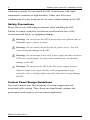
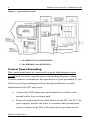
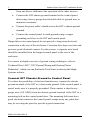
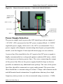
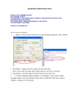
Watlow Silver Series EM Installation Guide Introduction Thank you for purchasing a Silver Series EM graphic operator interface terminal (OIT) from Watlow. The Silver Series EM OITs are configured using the EZwarePlus software (available separately from Watlow) and include the following models: Watlow P/N Maple Systems P/N 4.3” display TS00-0043-EM00 HMI5043L 7.0” display TS00-0070-EM00 HMI5070L 10” display TS00-0100-EM00 HMI5100L This booklet describes the steps necessary for installing the Silver Series EM OITs. Applications Assistance This manual is designed to provide the necessary in formation for trouble-free installation and operation of your new Operator Interface Terminal (OIT). However, if you need assistance, please call Watlow at (507) 494-5656 between 7 a.m. and 5 p.m. Central Standard Time (CST). Ask for an Applications Engineer. Or you may e-mail your questions to [email protected]. For information on programming and configuring the OIT, please refer to the EZwarePlus Programming Manual available from Watlow. 0600-0101-0000 Rev A 2 Watlow Silver Series OIT Installation Guide Static Awareness Do NOT remove the rear cover of your Silver Series EM product – doing so will void your warranty. When the rear cover is removed the circuitry inside is exposed to possible damage by electrostatic discharge during handling. Minimize the possibility of electrostatic discharge by: • • • • Discharging personal static by grounding yourself prior to handling the OIT. Handling the OIT at a static-free grounded workstation. Connecting the frame ground ( ) connector of the OIT to a clean earth ground. Placing the OIT in an antistatic bag during transport. Unpacking the Unit Carefully unpack the OIT. Please read any instructions or cautions that appear on the shipping container. Check all material in the container against the packing list. Examine the equipment carefully; if any shipping damage is evident, notify the carrier immediately. You are responsible for claim negotiations with the carrier. Save the shipping container and packing material in case the equipment needs to be stored, returned, or transported for any reason. Packing List Silver Series EM Touchscreen Power Connector Mounting Clamps Spare Fuse (Except HMI5043L) 0600-0101-0000 Rev A 3 Watlow Silver Series OIT Installation Guide Warranty Maple Systems warrants each product to be free from electrical and mechanical defects in materials and workmanship for a period of one (1) year for the LCD display and backlight and two (2) years for all other parts and labor from the date of shipment. This warranty does not apply to defects in the Products caused by abuse, misuse, accident, casualty, alteration, negligence, repair not authorized by Maple Systems, use on current or voltages other than specified by Maple Systems, or application or installation not in accordance with published instruction manuals. This warranty is in lieu of any other warranty either expressed or implied. Maple Systems liability is limited to the repair or replacement of the Product only, and not costs of installation, removal, or damage to user’s property or other liabilities. If Maple Systems is unable to repair or replace a nonconforming Product, it may offer a refund of the amount paid to Maple Systems for such Product in full satisfaction of its warranty obligation. Maximum liability of Maple Systems is the cost of the Product. Information furnished by Maple Systems, Inc., is believed to be accurate and reliable. However, no responsibility is assumed by Maple Systems for the use of this information, or for any infringements of patents or other rights of third parties which may result from its use. No license is granted by implication, or otherwise, under any patent or patent rights of Maple Systems, Inc. Maple Systems retains the right to revise or change its products and documentation at any time without notice. 0600-0101-0000 Rev A 4 Watlow Silver Series OIT Installation Guide Installation of OITs CE Compliance The Silver Series EM Graphic OITs have been tested to conform to European CE requirements, which meet or exceed the noise emissions and immunity requirements as set forth in the EN55022 (Emissions) and EN55024 (Immunity) standards. The products are designed to withstand electrical noise in harsh industrial environments. They also conform to requirements that limit electrical emissions. However, this does not guarantee that the products will be totally immune from possible malfunction in cases where severe electrical noise occurs. Therefore, we strongly recommend that you follow the guidelines outlined in this guide for proper wire routing and grounding to insure the proper operation of your graphic OIT. NEMA Rating The Silver Series EM is rated for NEMA 4 (indoor) or IP65/IP66 installations. This means that when the OIT is properly mounted to a NEMA 4 panel or other NEMA 4 rated enclosure, the front enclosure of the OIT will provide protection to the inside of the panel from splashing water, wind-blown dust, rain, or hose-directed water. The OIT must be installed according to the instructions in this manual to be properly sealed. Environmental Considerations The Silver Series EM is designed to operate in temperatures from 0° to 50°C (32° to 122°F). It is intended for indoor installations and may not be suitable for use in certain outdoor applications. Avoid installing the Silver Series EM touchscreens in environments with severe mechanical 0600-0101-0000 Rev A 5 Watlow Silver Series OIT Installation Guide vibration or shocks. Do not install the OIT in enclosures with rapid temperature variations or high humidity. Either case will cause condensation of water inside the device and eventual damage to the OIT. Safety Precautions Please observe the following precautions when installing the OIT. Failure to comply with these restrictions could result in loss of life, serious personal injury, or equipment damage. Warning: Do not operate the OIT in areas subject to explosion due to flammable gases, vapors, or dusts. Warning: Do not connect the OIT to an AC power source. You will cause permanent damage to the OIT. Warning: Do not attempt to use a DC power supply that does not meet OIT power requirements. You may cause malfunction or permanent damage to the OIT. Warning: Do not power the OIT with a DC power supply used for inductive loads or for input circuitry to the programmable logic controller. Severe voltage spikes caused by these devices may damage the OIT. Control Panel Design Guidelines Pay careful attention to the placement of system components and associated cable routing. These items can significantly enhance the performance and integrity of your control application. 0600-0101-0000 Rev A 6 Watlow Silver Series OIT Installation Guide Figure 1: Typical Panel Layout 1. Also HMI5121XL and HMI5150XL 2. Also HMI5043L and HMI5070NL Control Panel Grounding The control panel must be connected to a good, high-integrity earth ground both for safety considerations and shielding purposes. Maple Systems cannot overemphasize the importance of good grounding. If you fail to use good grounding procedures during installation, sporadic malfunction of the OIT may occur. • Connect the OITs chassis ground terminal to a reliable earth ground with a low-resistance path. • Route all earth ground wires that lead from the OIT, the PLC, the power supply, and the line filter to a central earth ground point such as a barrier strip. This will ensure that no ground current 0600-0101-0000 Rev A 7 Watlow Silver Series OIT Installation Guide from one device influences the operation of the other devices. • Connect the OIT chassis ground terminal to the control panel door using a heavy-gauge short braided cable or ground wire to minimize resistance. • Connect the power cable’s shield wire to the OIT’s chassis ground terminal. • Connect the control panel to earth ground using a copper grounding rod close to the OIT and control panel. Hinged doors on control panels do not provide a long-term electrical connection to the rest of the enclosure. Corrosion develops over time and prevents good electrical contact. For this reason, a separate wire braid should be installed from the hinged control panel to the rest of the enclosure. For a more in-depth overview of ground wiring techniques, refer to Technical Note #1027, “OIT Ground Wiring and Electrical Noise Reduction,” which you can find in the Tech Notes section on the Maple Systems website. Connect OIT Chassis Ground to Control Panel To reduce the possibility of electrical interference, connect the chassis ground terminal of the OIT to a clean earth ground. If the control panel is metal, make sure it is properly grounded. Then connect a short heavygauge wire (#14 AWG) from the chassis ground terminal of the OIT to a mounting bolt on the control panel door. The mounting bolt must have good electrical contact to the control panel; scrape away any paint that may be covering the panel to provide a good connection. 0600-0101-0000 Rev A 8 Watlow Silver Series OIT Installation Guide NOTE: If the control panel is made of a non-conductive material, it is essential that you connect the chassis ground terminal of the OIT to a clean earth ground point located close to the panel. NOTE: The power and frame ground wiring on the HMI5043L, and HMI5070L is different from the HMI5100L. Please refer to Figures 2a and 2b. Figure 2a: Chassis Ground Connection – TS00-0043-EM00 (HMI5043L), TS00-0070-EM00 (HMI5070L) Metal area on panel free of paint Frame ground Stud or screw Green (FG) Black (--) 0600-0101-0000 Rev A Red (+) Control Panel (connected to earth ground) 9 Watlow Silver Series OIT Installation Guide Figure 2b: Chassis Ground Connection – TS00-0100-EM00 (HMI5100L) Metal area on panel free of paint Stud or screw Frame ground Green (FG) Control Panel (connected to earth ground) Red (+) Black (--) Power Supply Selection The power supply used to power the OIT should provide an output of +24 VDC ±20% measured at the OIT power terminal block. A 24VDC regulated power supply dedicated to the OIT is recommended. Use a power supply with adequate current rating based upon your particular model (visit the Support Center Specifications page on our website). A power line filter installed at the AC input to the OIT power supply is highly recommended as a safeguard against conducted RF noise, which is often present on factory power lines. The wires connecting the output of the power line filter to the power supply should be kept as short as possible to minimize any additional noise pickup. The case of the power line filter should be connected to a quiet earth ground. The power line filter should have a current rating of at least 3 Amps with common mode and differential mode attenuation. In applications that may have high frequency noise present, we also recommend using a resistor (~1 MΩ) 0600-0101-0000 Rev A 10 Watlow Silver Series OIT Installation Guide and capacitor (~4700 pF) in parallel to clean earth ground on the DC output of the power supply. Do not use the power supply used to provide power to the OIT to power switching relays, solenoids, or other active devices. Figure 3: Power Line Filter Connection Cable Routing and Noise Immunity Follow these guidelines when routing cables to the OIT: • Always route the OIT communication cable and the power cable away from any AC voltage or rapidly switching DC control lines. • Never bundle the OIT cables together with 120VAC power wires or with relay wiring. • Try to keep at least 8 inches (20 cm) of separation between the OIT cables and other power wiring. If voltages greater than 120VAC are used in the system, greater separation is required. • If the OIT cables must come near AC wiring, make sure they cross at 90 degrees. • Run AC power wires in a separate grounded conduit to reduce electrical noise interference. • Keep the cable lengths for the OIT as short as possible. Do not 0600-0101-0000 Rev A 11 Watlow Silver Series OIT Installation Guide coil excess cable and place it next to AC powered equipment. • Cover any equipment used in the enclosure that operates at high frequency or high current levels with a grounded metal shield. Installation It is necessary to follow all installation procedures described in this chapter for electrical noise immunity and CE compliance. Your Maple Systems OIT is designed to connect easily to your PLC. External rear connectors provide quick connections for power, communications and programming wiring. Connect the OIT to Power Use the separate 3-position terminal block supplied with the OIT to provide power to the OIT. The power cable for the OIT should be 18AWG, 2-conductor wire with a shield drain wire and protective shield (foil/braid). You may buy cable P/N 6030-0009 by the foot from Maple Systems to make your own power cable. Always run the DC ground wire directly back to the signal return of the power supply. Do not use the chassis ground wire as your signal return. Caution: To prevent possible damage to the OIT, we recommend waiting ten seconds after removing power to the OIT before applying power again. 0600-0101-0000 Rev A 12 Watlow Silver Series OIT Installation Guide Figure 4: OIT Power Wiring To connect the OIT to power: 1. Connect the power cable to the OIT. a. Strip the power cable shield to expose 2” of the black and red wires. b. Strip about ¼” of insulation from the black and red wires. c. Connect the red wire to the 24V DC positive (+) input of the OIT power terminal block. d. Connect the black wire to the 24V DC negative (–) input of the OIT power terminal block. e. Connect the power cable shield wire to the OIT power terminal block’s chassis ground input. 2. Route the power cable to the OIT power supply. The power cable should not be any longer than necessary. 0600-0101-0000 Rev A 13 Watlow Silver Series OIT Installation Guide 3. Install the power supply wires as follows (with colors shown for Maple Systems cable P/N 6030-0009): Color Red Black Shield Power Supply +Output/+24V DC –Output/+24V DC return Case ground OIT +24 V GND FG or NOTE: The power connector on the Silver Series EM uses a 3-position terminal block with screw-down clamps. Lugs are not required. Panel Preparation A metal panel or mounting surface with a minimum thickness of 15 gauge (0.059 in/3.3 mm) if cold-rolled steel or hardened steel, or 10 gauge (0.101 in/2.6 mm) if aluminum alloy (6061-T6 preferred) is required. Thinner panels or surfaces may bow between the mounting clamps and not form a seal with the gasket. Make sure all supplied mounting clamps are used and that the panel does not flex or bow more than 0.010 in. to ensure a proper seal. The OIT should be mounted into a panel with a depth of at least 4 in. (105 mm). Allow a clearance of at least 1 in. (25 mm) on each side for mounting hardware. Consider proper clearance for cable connections when mounting. NOTE: Cutout dimensions for each particular OIT model are readily available for download from the Support Center-Dimensional Drawings section of the Maple Systems website. The area of the panel or mounting surface where the gasket comes into contact must be flat and free of scratches, pits, and other features that prevent the gasket from sealing properly. If the panel or mounting 0600-0101-0000 Rev A 14 Watlow Silver Series OIT Installation Guide surface is not uniform, thick, flat, stiff, or smooth enough, then a sealant such as silicone may be required. NOTE: Clean and deburr the panel cutout before the OIT is installed. Warning: The OIT requires a stiff, flat, smooth mounting surface free of blemishes to seal properly to NEMA 4. All supplied mounting clamps must be used and the panel cannot flex more than 0.010”. Mount the OIT to the Panel Figure 5: Installing Screw Clamps to the OIT Note: The clamps for your model may be slightly different than shown here, but essentially work in the same way. STEPS: 1. Prepare the clamps for the OIT by inserting the screws into the clamp as shown above. Position the screws so that the ends don’t protrude through the clamp’s hole. 0600-0101-0000 Rev A 15 Watlow Silver Series OIT Installation Guide 2. Set the OIT in the panel cutout and hold it in place until all clamps are in position. 3. Tighten the screw clamps in an even pattern until all are uniformly snug. Caution: Do not over-tighten the screws beyond snugness or you may damage the housing or warp the overlay. REINSTALLATION: If, at any time, you are required to reinstall an OIT into a panel, be aware that the gasket will take a ‘set’ to the panel and may no longer provide an adequate NEMA 4 seal. Therefore, for best results, we recommend that you replace the gasket if reinstallation is required. Configuration Wiring To configure the OIT using the EZwarePlus software, you will need an Ethernet cable. Ethernet If using a switch or router between the PC and the OIT, use a straightthrough or crossover cable as required by the switch or router. 0600-0101-0000 Rev A 16 Watlow Silver Series OIT Installation Guide Maintenance Figure 6: DIP switch positions (power must be cycled on the OIT to enable the DIP switch mode). (Except HMI5043L) SW1 ON OFF OFF OFF OFF SW2 OFF ON OFF OFF OFF SW3 OFF OFF ON OFF OFF SW4 OFF OFF OFF ON OFF Mode Calibration mode Hide System Toolbar Force into Boot Loader mode Reserved Normal operation Touchscreen Calibration mode: This mode allows you to recalibrate the touchscreen. Units without DIP switches have a Calibration button on the system toolbar. Hide System Toolbar: Hides the arrow in the bottom-right corner of the screen that accesses the System Toolbar (same as “Hide System Toolbar” in System Parameters and LB9020). Boot Loader mode: This mode forces the OIT to not execute the project. This mode is used when replacing or reinstalling the operating system. All units have an Upgrade Firmware button in the system menus. Contact Maple Systems for more information. Fusing Requirements If the display does not come on within two seconds of power up, remove power. An internal fuse (except HMI5043L) will prevent damage if the polarity of the DC power is incorrect. Check wiring to insure proper connections and try to power up again. 0600-0101-0000 Rev A 17 Watlow Silver Series OIT Installation Guide Serial Port Connections The diagrams below indicate the proper pin connections for the serial ports of the Silver Series EM. Figure 7a: Serial Port Pinouts TS00-0043-EM00 (HMI5043L) 0600-0101-0000 Rev A 18 Watlow Silver Series OIT Installation Guide Figure 7b: Serial Port Pinouts TS00-0100-EM00 (HMI5100L), TS00-0070-EM00 (HMI5070L) TS00-0100-EM00 TS00-0070-EM00 0600-0101-0000 Rev A