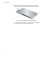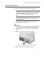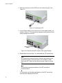
1
AT-GS908M AT-GS916M AT-GS924M Gigabit Ethernet Switches Installation Guide 613-001986 Rev A Copyright © 2014 Allied Telesis, Inc. All rights reserved. No part of this publication may be reproduced without prior written permission from Allied Telesis, Inc. Allied Telesis and the Allied Telesis logo are trademarks of Allied Telesis, Incorporated. All other product names, company names, logos or other designations mentioned herein are trademarks or registered trademarks of their respective owners. Allied Telesis, Inc. reserves the right to make changes in specifications and other information contained in this document without prior written notice. The information provided herein is subject to change without notice. In no event shall Allied Telesis, Inc. be liable for any incidental, special, indirect, or consequential damages whatsoever, including but not limited to lost profits, arising out of or related to this manual or the information contained herein, even if Allied Telesis, Inc. has been advised of, known, or should have known, the possibility of such damages. Electrical Safety and Emissions Standards This product meets the following standards. U.S. Federal Communications Commission Radiated Energy Note: This equipment has been tested and found to comply with the limits for a Class A digital device pursuant to Part 15 of FCC Rules. These limits are designed to provide reasonable protection against harmful interference when the equipment is operated in a commercial environment. This equipment generates, uses, and can radiate radio frequency energy and, if not installed and used in accordance with this instruction manual, may cause harmful interference to radio communications. Operation of this equipment in a residential area is likely to cause harmful interference in which case the user will be required to correct the interference at his own expense. Note: Modifications or changes not expressly approved of by the manufacturer or the FCC, can void your right to operate this equipment. Industry Canada This Class A digital apparatus meets all requirements of the Canadian Interference-Causing Equipment Regulations. Cet appareil numérique de la classe A respecte toutes les exigences du Règlement sur le matériel brouilleur du Canada. RFI Emissions FCC Class A, EN55022 Class A, EN61000-3-2, EN61000-3-3, RCM, CE Warning: In a domestic environment this product may cause radio interference in which case the user may be required to take adequate measures. Immunity EN55024 Electrical Safety EN60950-1 (ULEU), UL 60950-1 (CULUS) Laser Safety EN60825 3 Translated Safety Statements Important: The indicates that a translation of the safety statement is available in a PDF document titled Translated Safety Statements posted on the Allied Telesis website at www.alliedtelesis.com/support. 4 Contents Preface ................................................................................................................................................................................11 Symbol Conventions .................................................................................................................................. 12 Contacting Allied Telesis............................................................................................................................ 13 Chapter 1: Overview ...................................................................................................................................... 15 Features ..................................................................................................................................................... 16 Twisted-Pair Ports ............................................................................................................................... 16 SFP Slots............................................................................................................................................. 16 LEDs.................................................................................................................................................... 17 Installation Options .............................................................................................................................. 17 MAC Address Table ............................................................................................................................ 17 Front and Back Panels............................................................................................................................... 18 Management Software ............................................................................................................................... 20 Twisted-Pair Ports...................................................................................................................................... 21 Combo Ports .............................................................................................................................................. 22 LEDs .......................................................................................................................................................... 23 STATUS LEDs..................................................................................................................................... 23 MODE LEDs ........................................................................................................................................ 24 Port LEDs ............................................................................................................................................ 25 SFP Slot LEDs..................................................................................................................................... 26 Reset Button .............................................................................................................................................. 28 Mode Button............................................................................................................................................... 29 Power Supply ............................................................................................................................................. 30 Chapter 2: Installation ................................................................................................................................... 31 Reviewing Safety Precautions ................................................................................................................... 32 Selecting a Site for the Switch ................................................................................................................... 35 Cable Specifications................................................................................................................................... 36 Unpacking the Switch................................................................................................................................. 37 Installing the Power Cord Retaining Clip.................................................................................................... 39 Installing the Switch on a Desktop or Table ............................................................................................... 40 Installing the Switch in an Equipment Rack ............................................................................................... 41 Installing SFP Transceivers ....................................................................................................................... 43 Cabling the Switch ..................................................................................................................................... 46 Powering On the Switch............................................................................................................................. 47 Chapter 3: Troubleshooting ......................................................................................................................... 49 Appendix A: Technical Specifications ........................................................................................................ 51 Physical Specifications............................................................................................................................... 51 Dimensions.......................................................................................................................................... 51 Weight ................................................................................................................................................. 51 Environmental Specifications ..................................................................................................................... 52 Power Specifications.................................................................................................................................. 52 Safety and Electromagnetic Emissions Certifications ................................................................................ 52 Connectors and Port Pinouts ..................................................................................................................... 53 5 Contents 6 Figures Figure 1: AT-GS908M, AT-GS916M, and AT-GS924M Front Panels ................................................................................. Figure 2: AT-GS908M, AT-GS916M, and AT-GS924M Back Panels.................................................................................. Figure 3: STATUS LEDs...................................................................................................................................................... Figure 4: MODE LEDs ......................................................................................................................................................... Figure 5: Port LEDs ............................................................................................................................................................. Figure 6: SFP Slot LEDs ..................................................................................................................................................... Figure 7: Shipping Package Contents ................................................................................................................................. Figure 8: Power Cord Retaining Clip ................................................................................................................................... Figure 9: Inserting the Retaining Clip into the Retaining Bracket ........................................................................................ Figure 10: Attaching the Rack-Mount Brackets to the Switch.............................................................................................. Figure 11: Mounting the Switch in an Equipment Rack ....................................................................................................... Figure 12: Removing the Dust Plug from an SFP Slot ........................................................................................................ Figure 13: Inserting the SFP................................................................................................................................................ Figure 14: Positioning the SFP Handle in the Upright Position ........................................................................................... Figure 15: Plugging in the AC Power Cord.......................................................................................................................... Figure 16: RJ-45 Connector and Port Pin Layout................................................................................................................ 18 19 23 25 25 26 38 39 39 41 42 43 44 44 47 53 7 List of Figures 8 Tables Table 1. Combo Ports .........................................................................................................................................................22 Table 2. POWER LED Functional Description ....................................................................................................................23 Table 3. FAULT LED Functional Description ......................................................................................................................24 Table 4. STANDBY LED Functional Description ................................................................................................................24 Table 5. MODE LED Functional Descriptions .....................................................................................................................25 Table 6. Port LED Functional Descriptions .........................................................................................................................26 Table 7. SFP Slot LED Functional Descriptions .................................................................................................................27 Table 8. Twisted-Pair Cabling and Distances .....................................................................................................................36 Table 9. Chassis Dimensions .............................................................................................................................................51 Table 10. Chassis Weight ...................................................................................................................................................51 Table 11. Environmental Specifications ..............................................................................................................................52 Table 12. Power Specifications ..........................................................................................................................................52 Table 13. Safety and Electromagnetic Emissions Certifications .........................................................................................52 Table 14. MDI Pin Signals (10Base-T or 100Base-TX) ......................................................................................................53 Table 15. MDI-X Pin Signals (10Base-T or 100Base-TX) ..................................................................................................53 Table 16. RJ-45 1000Base-T Connector Pinouts ...............................................................................................................54 9 List of Tables 10 Preface This guide contains the installation instructions for the AT-GS908M, ATGS916M, and AT-GS924M Gigabit Ethernet Switches. This preface contains the following sections: “Symbol Conventions” on page 12 “Contacting Allied Telesis” on page 13 11 Symbol Conventions This document uses the following conventions: Note Notes provide additional information. Caution Cautions inform you that performing or omitting a specific action may result in equipment damage or loss of data. Warning Warnings inform you that performing or omitting a specific action may result in bodily injury. Warning Warnings inform you that an eye and skin hazard exists due to the presence of a Class 1 laser device. 12 AT-GS908M, AT-GS916M, and AT-GS924M Switches Installation Guide Contacting Allied Telesis If you need assistance with this product, you may contact Allied Telesis technical support by going to the Support & Services section of the Allied Telesis web site at www.alliedtelesis.com/support. You can find links for the following services on this page: 24/7 Online Support — Enter our interactive support center to search for answers to your product questions in our knowledge database, check support tickets, learn about Return Merchandise Authorizations (RMAs), and contact Allied Telesis technical experts. USA and EMEA phone support - Select the phone number that best fits your location and customer type. Hardware warranty information - Learn about Allied Telesis warranties and register your product online. Replacement Services — Submit an RMA request via our interactive support center. Documentation - View the most recent installation guides, user guides, software release notes, white papers and data sheets for your product. Software Updates - Download the latest software releases for your product. For sales or corporate contact information, go to www.alliedtelesis.com/ purchase and select your region. 13 14 Chapter 1 Overview This chapter provides descriptions of the AT-GS908M, AT-GS916M, and AT-GS924M Layer 2 Gigabit Ethernet Switches and contains the following sections: “Features” on page 16 “Front and Back Panels” on page 18 “Management Software” on page 20 “Twisted-Pair Ports” on page 21 “Combo Ports” on page 22 “LEDs” on page 23 “Reset Button” on page 28 “Mode Button” on page 29 “Power Supply” on page 30 15 Chapter 1: Overview Features Here are the hardware features of the AT-GS900M Series Gigabit Ethernet Switches. Twisted-Pair Ports SFP Slots Here are the basic features of the 10/100/1000 Mbps twisted-pair ports: 8, 16, or 24 ports per switch 10Base-TX, 100Base-T and 1000Base-T compliant IEEE 802.3u Auto-Negotiation compliant Auto-MDI/MDIX 100 meters (328 feet) maximum operating distance IEEE 802.3x Flow Control in 10/100Base-TX full-duplex operation IEEE 802.3x Back Pressure in 10/100Base-TX half-duplex operation IEEE803.3z 1000Base-T Flow Control RJ-45 connectors All three switches support both 100Base-FX and 1000Base-SX/LX transceivers. The switches support slots for SFPs as follows: One SFP slot on the AT-GS908M switch Two SFP slots on the AT-GS916M switch Four SFP slots on the AT-GS924M switch Note The AT-GS916M and AT-GS924M SFP slots are paired with twisted-pair ports on the switch to form combo ports. For more information, see “Combo Ports” on page 22. Note You must purchase SFP transceivers separately. For a list of supported transceivers, contact your Allied Telesis distributor or reseller. Note See the product data sheets for the specific ATI SFP modules supported by the AT-GS900M Series switches. 16 AT-GS908M, AT-GS916M, and AT-GS924M Switches Installation Guide LEDs Installation Options The following lists the switch LEDs: Power LED; refer to “POWER LED” on page 23. Fault LED; refer to “FAULT LED” on page 24. Standby LED; refer to“STANDBY LED” on page 24. Speed and Duplex Mode LEDs; refer to “MODE LEDs” on page 24. Speed/Duplex and Link/Activity LEDs for the twisted-pair ports; refer to “Port LEDs” on page 25. Link/Activity LEDs for the SFP slots; refer to “SFP Slot LEDs” on page 26. The AT-GS900M Series switches can be installed in the following ways: Rack mounted in a 19-inch equipment rack Mounted on a desk or tabletop If installing the switch in an equipment rack, rack mounting equipment provided with the switch depends on the switch model as follows: MAC Address Table AT-GS908M: rack mounting equipment must be purchased separately. The rack mounting kit model number is AT-RKMT-J05. AT-GS916M and AT-GS924M: rack mounting hardware is included in the shipping package. Here are the basic features of the MAC address table: Storage capacity up to 8KB MAC address entries Automatic learning and aging 17 Chapter 1: Overview Front and Back Panels Figure 1 illustrates the front panels of the AT-GS908M, AT-GS916M, and AT-GS924M Gigabit Ethernet Switches. AT-GS908M Mode SFP LED LEDs SFP Slot Mode Reset Button Port LEDs 10/100/1000Base-T Status LEDs Button Twisted-Pair Ports Console Port AT-GS916M Mode LEDs Reset Button Mode Status LEDs Button Console Port Port LEDs 10/100/1000Base-T Twisted-Pair Ports SFP LEDs SFP Slots AT-GS924M Mode LEDs Mode Status LEDs Button Console Port Reset Button Port LEDs 10/100/1000Base-T Twisted-Pair Ports SFP LEDs SFP Slots Figure 1. AT-GS908M, AT-GS916M, and AT-GS924M Front Panels 18 AT-GS908M, AT-GS916M, and AT-GS924M Switches Installation Guide Figure 2 illustrates the back panels of the AT-GS908M, AT-GS916M, and AT-GS924M switches. AT-GS908M AC Input AT-GS916M AC Input AT-GS924M AC Input Figure 2. AT-GS908M, AT-GS916M, and AT-GS924M Back Panels 19 Chapter 1: Overview Management Software The switches are shipped with the ATPro management software preinstalled. The software provides a web-browser interface for in-band, overthe-network management. In the unlikely event that the management software becomes corrupted or damaged on the switch, you can download the software from the Allied Telesis corporate web site and reinstall it on the switch. For instructions on how to install new management software, see the product documentation. 20 AT-GS900M Series Management Software Web User’s Guide AT-GS900M Series Command Line Interface User’s Guide AT-GS908M, AT-GS916M, and AT-GS924M Switches Installation Guide Twisted-Pair Ports The AT-GS908M, AT-GS916M, and AT-GS924M Layer 2 Gigabit Ethernet Switches feature 8, 16, and 24 twisted-pair ports, respectively. All ports are 10Base-T, 100Base-TX, and 1000Base-TX compliant. You can set the port speeds and duplex modes either automatically with IEEE 802.3u Auto-Negotiation or manually with the management software. The twisted-pair ports feature 8-pin RJ-45 connectors. For the port pinouts, see “Connectors and Port Pinouts” on page 53. The ports have a maximum operating distance of 100 m (328 feet). For 10 Mbps operation, the ports require Category 3 or better 100 ohm shielded or unshielded twisted-pair cabling. For 100 or 1000 Mbps operation, the ports require Category 5 or Enhanced Category 5 (5E) 100 ohm shielded or unshielded twisted-pair cabling. The ports feature auto-MDI, which automatically configures the ports as MDI or MDI-X. This feature allows you to use straight-through twisted-pair cables, regardless of the wiring configurations of the ports on the end nodes. Note A switch port connected to an end node that is not using AutoNegotiation should not use Auto-Negotiation to set the speed and duplex mode, because a duplex-mode mismatch may occur. In this case, disable Auto-Negotiation and set the port’s speed and duplex mode manually. 21 Chapter 1: Overview Combo Ports The AT-GS916M Switch has two combo ports, and the AT-GS924M Switch has four combo ports. Each combo port consists of one 10/100/ 1000Base-T twisted-pair port and one slot for an optional 100Base-FX or 1000Base-SX/LX SFP transceiver. The twisted-pair ports are identified with the letter “R” for “Redundant” on the front faceplates of the units. The combo ports and slots are listed in Table 1. Table 1. Combo Ports Switch AT-GS916M AT-GS924M Twisted-Pair Port SFP Slot 15R 15 16R 16 15R 15 16R 16 23R 23 24R 24 The combo ports have the guidelines listed here: 22 Only one port in a pair, either the twisted-pair port or a corresponding SFP module, can be active at a time. The twisted-pair port is the active port when its SFP slot is empty, or when an SFP module is installed, but has not established a link to an end node. The twisted-pair port automatically changes to the redundant status mode when an SFP module establishes a link with an end node. A twisted-pair port automatically transitions back to the active status when the link is lost on the SFP module. In nearly all cases, a twisted-pair port and an SFP module share the same configuration settings, including port settings, VLAN assignments, access control lists, and spanning tree. An exception to the shared settings is port speed. If you disable Auto-Negotiation on a twisted-pair port and set the speed and duplex mode manually, the speed reverts to Auto-Negotiation when an SFP module establishes a link with an end node. AT-GS908M, AT-GS916M, and AT-GS924M Switches Installation Guide LEDs There are four types of LEDs on the AT-GS900M Series switches: STATUS LEDs “STATUS LEDs” “MODE LEDs” on page 24 “Port LEDs” on page 25 “SFP Slot LEDs” on page 26 STATUS LEDs display the status of the switch. STATUS LEDs are as follows: “POWER LED” “FAULT LED” on page 24 “STANDBY LED” on page 24 The STATUS LEDs are located on the left side of the front panel of the switch. See Figure 3. STATUS LEDs Reset Button Figure 3. STATUS LEDs POWER LED The POWER LED reports the status of AC power. Table 2 describes the states of the POWER LED. Table 2. POWER LED Functional Description State Description Off Indicates either the switch is not receiving AC power or the AC input power is operating outside the normal range. Steady Green The switch is receiving AC input power and is operating normally. 23 Chapter 1: Overview FAULT LED The FAULT LED reports any conditions on the switch that are not normal. Table 3 describes the states of the FAULT LED. Table 3. FAULT LED Functional Description State Off Steady Red Flashing Red Description Normal switch operation. Abnormal system operation. One of following: Firmware downloading and being written to flash memory. DC internal power operating outside the normal range. Temperature out of range. STANDBY LED The STANDBY LED indicates whether the power is in a standby state. Table 4 describes the states of the STANDBY LED. Table 4. STANDBY LED Functional Description State Off Steady Green Description Power not in standby state. Power in standby state. Note The management web interface or CLI is used to set the Standby state. MODE LEDs The MODE LEDs display which mode is selected on the switch: Speed or Duplex. The mode is selected using the Mode button, located on the left side of the front panel of the switch. For a description of the Mode button, refer to “Mode Button” on page 29. The MODE LEDs are located on the left side of the front panel of the switch. See Figure 4 on page 25. 24 AT-GS908M, AT-GS916M, and AT-GS924M Switches Installation Guide MODE LEDs Mode Button Figure 4. MODE LEDs Table 5 describes the MODE LEDs for the AT-GS900M Series switches. Table 5. MODE LED Functional Descriptions LED State Steady Green SPEED DUPLEX Off Steady Green Off Port LEDs Description SPEED is the selected mode. Ports display SPEED status. SPEED is not the selected mode. Ports display DUPLEX status. DUPLEX is the selected mode. Ports display DUPLEX status. DUPLEX is not the selected mode. Ports display SPEED status. The Port LEDs report the link activity and speed status of each 10/100/ 1000 BaseT port. The Port LEDs are shown in Figure 5. Figure 5. Port LEDs Table 6 on page 26 describes the Port LEDs for the AT-GS900M Series switches. 25 Chapter 1: Overview . Table 6. Port LED Functional Descriptions LED Link/Activity State Description Off The port has not established a link with a network device. On The port has established a link with a network device. Flashing Green Off If SPEED is selected by the Mode switch, the maximum operating speed of the port is 10 or 100 Mbps or link not established. Steady Green If SPEED is selected by the Mode switch, the maximum operating speed of the port is 1000 Mbps. Off If DUPLEX is selected by the Mode switch, half-duplex link established or link not established. Speed/Duplex Steady Green SFP Slot LEDs The port is transmitting or receiving network packets. If DUPLEX is selected by the Mode switch, full-duplex link established. The SFP Slot LEDs report the link activity status of each SFP slot. The AT-GS924M SFP Slot LEDs are shown in Figure 6. SFP/Slot LEDs Figure 6. SFP Slot LEDs Table 7 on page 27 describes the SFP Slot LEDs for the AT-GS900M Series switches. 26 AT-GS908M, AT-GS916M, and AT-GS924M Switches Installation Guide . Table 7. SFP Slot LED Functional Descriptions LED Link/Activity State Description Off The port has not established a link with a network device. On The port has established a link with a network device. Flashing Green The port is transmitting or receiving network packets. 27 Chapter 1: Overview Reset Button Pressing the Reset button resets your switch. The Reset button is located next to the STATUS LEDs. See Figure 3 on page 23. This initiates a system reboot of the switch and reloads the current configuration file. Caution The switch does not forward network traffic during the reset process. 28 AT-GS908M, AT-GS916M, and AT-GS924M Switches Installation Guide Mode Button Use the Mode button to select whether the Port LEDs display the Link Activity or speed and duplex status. The Mode button is located next to the MODE LEDs. See Figure 4 on page 25. 29 Chapter 1: Overview Power Supply Each switch has an internal power supply with a single AC power supply socket on the back panel. To power the switch on or off, connect or disconnect the power cord provided with the switch. A power cord is supplied with the switch. Note For the power requirements, see the “Power Specifications” on page 52. 30 Chapter 2 Installation This chapter contains the following sections: “Reviewing Safety Precautions” on page 32 “Selecting a Site for the Switch” on page 35 “Cable Specifications” on page 36 “Unpacking the Switch” on page 37 “Installing the Power Cord Retaining Clip” on page 39 “Installing the Switch on a Desktop or Table” on page 40 “Installing the Switch in an Equipment Rack” on page 41 “Installing SFP Transceivers” on page 43 “Cabling the Switch” on page 46 “Powering On the Switch” on page 47 31 Chapter 2: Installation Reviewing Safety Precautions Please review the following safety precautions before you begin to install the chassis or any of its components. Note The indicates that a translation of the safety statement is available in a PDF document titled Translated Safety Statements posted on the Allied Telesis website at www.alliedtelesis.com/ support. Warning To prevent electric shock, do not remove the cover. No userserviceable parts inside. This unit contains hazardous voltages and should only be opened by a trained and qualified technician. To avoid the possibility of electric shock, disconnect electric power to the product before connecting or disconnecting the cables. E1 Warning Do not work on equipment or cables during periods of lightning activity. E2 Warning Power cord is used as a disconnection device. To de-energize equipment, disconnect the power cord. E3 Warning Class I Equipment. This equipment must be earthed. The power plug must be connected to a properly wired earth-ground socket outlet. An improperly wired socket outlet could place hazardous voltages on accessible metal parts. E4 Note Pluggable Equipment. The socket outlet shall be installed near the equipment and shall be easily accessible. E5 32 AT-GS908M, AT-GS916M, and AT-GS924M Switches Installation Guide Caution Air vents must not be blocked and must have free access to the room ambient air for cooling. E6 Warning Operating Temperature. This product is designed for a maximum ambient temperature of 50° C. E57 Note All Countries: Install product in accordance with local and National Electrical Codes. E8 Note Circuit Overloading: Consideration should be given to the connection of the equipment to the supply circuit and the effect that overloading of circuits might have on over-current protection and supply wiring. Appropriate consideration of equipment nameplate ratings should be used when addressing this concern. E21 Warning Mounting of the equipment in the rack should be such that a hazardous condition is not created due to uneven mechanical loading. E25 Note If installed in a closed or multi-unit rack assembly, the operating ambient temperature of the rack environment may be greater than the room ambient temperature. Therefore, consideration should be given to installing the equipment in an environment compatible with the manufacturer’s maximum rated ambient temperature (Tmra). E35 Caution Installation of the equipment in a rack should be such that the amount of air flow required for safe operation of the equipment is not compromised. E36 33 Chapter 2: Installation Warning Reliable earthing of rack-mounted equipment should be maintained. Particular attention should be given to supply connections other than direct connections to the branch circuits (for example, use of power strips). E37 34 AT-GS908M, AT-GS916M, and AT-GS924M Switches Installation Guide Selecting a Site for the Switch Observe the following requirements when choosing a site for your switch: If you plan to install the switch in an equipment rack, verify that the rack is safely secured and will not tip over. Devices in a rack should be installed starting at the bottom, with the heavier devices near the bottom of the rack. If you are installing the switch on a table, verify that the table is level and secure. The power outlet for the switch should be located near the unit and should be easily accessible. The site should provide for easy access to the ports on the front of the switch. This will make it easier for you to connect and disconnect cables, as well as view the switch’s LEDs. Air flow around the unit and through its vents on the side and rear should not be restricted so that the switch can maintain adequate cooling. Do not place objects on top of the switch. Do not expose the switch to moisture or water. Ensure that the site is a dust-free environment. You should use dedicated power circuits or power conditioners to supply reliable electrical power to the network devices. 35 Chapter 2: Installation Cable Specifications Table 8 contains the cable specifications for the twisted-pair ports. Table 8. Twisted-Pair Cabling and Distances Maximum Operating Distance Speed Type of Cable 10 Mbps Standard TIA/EIA 568-B-compliant Category 3 or better shielded or unshielded cabling with 100 ohm impedance and a frequency of 16 MHz. 100 m (328 ft) 100 Mbps Standard TIA/EIA 568-A-compliant Category 5 or TIA/EIA 568-Bcompliant Enhanced Category 5 (Cat 5e) shielded or unshielded cabling with 100 ohm impedance and a frequency of 100 MHz. 100 m (328 ft) 1000 Mbps Standard TIA/EIA 568-A-compliant Category 5 or TIA/EIA 568-Bcompliant Enhanced Category 5 (Cat 5e) shielded or unshielded cabling with 100 ohm impedance and a frequency of 100 MHz. 100 m (328 ft) Note The twisted-pair ports on the switch feature auto-MDI when operating at 10, 100, or 1000 Mbps. A port is configured as MDI or MDI-X when it is connected to an end node. Consequently, you can use a straight-through twisted-pair cable when connecting any type of network device to a port on the switch. 36 AT-GS908M, AT-GS916M, and AT-GS924M Switches Installation Guide Unpacking the Switch To unpack the switch, perform the following procedure: 1. Remove all of the components from the shipping package. Note Store the packaging material in a safe location. You must use the original shipping material if you need to return the unit to Allied Telesis. 2. Place the switch on a level, secure surface. 3. In addition to the switch, verify that the shipping container includes the following items shown in Figure 7 on page 38. Note For the AT-GS908M, rack mounting equipment (brackets and screws) is not included in the shipping package and must be purchased separately. Its rack mounting kit model number is ATRKMT-J05. 37 Chapter 2: Installation AT-GS916M brackets AT-GS924M brackets Two equipment rack brackets (not included in ATGS908M package) Four or six bracket screws (not included in ATGS908M package) AT-GS916M: 4 each AT-GS924M: 6 each Retaining clip Management cable Four rubber feet (pre-installed) (for desktop installation) One regional AC power cord One, two, or four SFP slot dust covers (pre-installed). Figure 7. Shipping Package Contents 38 AT-GS908M, AT-GS916M, and AT-GS924M Switches Installation Guide Installing the Power Cord Retaining Clip Perform the following procedure to install the power cord retaining clip on the AT-GS900M switch: 1. Locate the power cord retaining clip, as shown in Figure 8. Figure 8. Power Cord Retaining Clip 2. Install the clip on the AC power connector on the back panel of the switch. With the “u” of the clip facing down, press the sides of the clip toward the center and insert the short ends into the holes in the retaining bracket, as shown in Figure 9. Figure 9. Inserting the Retaining Clip into the Retaining Bracket 39 Chapter 2: Installation Installing the Switch on a Desktop or Table You may install the switches on a desktop or table, or in a standard 19inch equipment rack. To install the switch in a rack, see “Installing the Switch in an Equipment Rack” on page 41. To place the switch on a desktop or table, perform the following procedure: 1. Remove all equipment from the package and store the packaging material in a safe place. 2. Place the switch on a flat, secure surface (such as a desk or table) leaving ample space around the unit for ventilation. 3. Go to “Installing SFP Transceivers” on page 43 or “Cabling the Switch” on page 46. 40 AT-GS908M, AT-GS916M, and AT-GS924M Switches Installation Guide Installing the Switch in an Equipment Rack Note The AT-GS916M and AT-GS924M rack mounting hardware is included in the shipping package. However, the AT-GS908M rack mounting equipment must be purchased separately. The rack mounting kit model number is AT-RKMT-J05. To install the switch in a standard 19-inch equipment rack, perform the following procedure: 1. If the rubber feet are attached to the bottom of the switch, remove them using a flat-head screwdriver. 2. Attach the two rack mount brackets to the sides of the switch using the bracket screws that come with the unit. See Figure 10. AT-GS916M AT-GS924M Figure 10. Attaching the Rack-Mount Brackets to the Switch 41 Chapter 2: Installation 3. Mount the switch in a standard 19-inch equipment rack using four equipment rack screws (not provided with the switch). See Figure 11. Figure 11. Mounting the Switch in an Equipment Rack 4. Go to “Installing SFP Transceivers” on page 43 or skip to “Cabling the Switch” on page 46 if not installing SFP transceivers. 42 AT-GS908M, AT-GS916M, and AT-GS924M Switches Installation Guide Installing SFP Transceivers To install an SFP transceiver, perform the following procedure: Note The transceiver can be hot-swapped; you do not need to power off the switch to install a transceiver. However, you should always remove the cables before removing the transceiver. Note You should always install the transceiver before connecting the fiber-optic cables to it. 1. Remove the transceiver from its shipping container and store the packaging material in a safe location. Warning An SFP transceiver can be damaged by static electricity. Be sure to observe all standard electrostatic discharge (ESD) precautions, such as wearing an antistatic wrist strap, to avoid damaging the transceiver. 2. Remove the dust plug from an SFP slot. See Figure 12. Figure 12. Removing the Dust Plug from an SFP Slot 3. Position the SFP transceiver with the label facing up. 43 Chapter 2: Installation 4. Slide the transceiver into the SFP slot until it clicks into place. See Figure 13. Figure 13. Inserting the SFP 5. Verify that the handle on the transceiver is in the upright position, as shown in Figure 14. This secures the transceiver and prevents it from being dislodged from the slot. SFP Transceiver Handle Figure 14. Positioning the SFP Handle in the Upright Position 6. Repeat Step 2 through Step 5 to install additional SFP transceivers. Note SFP transceivers are dust-sensitive. Always keep the plug in the optical bores when a fiber-optic cable is not installed, or when storing the SFP. When you do remove the plug, keep it for future use. Note Unnecessary removal and insertion of an SFP can lead to premature failure. For information on the cable specifications of the SFP, consult the documentation shipped with the SFP. 44 AT-GS908M, AT-GS916M, and AT-GS924M Switches Installation Guide 7. Go to “Cabling the Switch” on page 46. 45 Chapter 2: Installation Cabling the Switch Observe the following guidelines when connecting twisted-pair and fiberoptic cables to the ports on the switch: 46 The connector on the cable should fit snugly into the port on the switch. The tab on the connector should lock the connector into place. Because the twisted-pair ports have auto-MDI/MDI-X, you may use straight-through twisted-pair cable to connect any type of network device to the switch. If your network topology contains a loop where two or more network devices can communicate with each other over more than one network path, do not connect the network cables that form the loop until after you activate a spanning tree protocol on the switch. Data loops can adversely affect network performance. If you are creating a port trunk, do not connect the cables of the trunk to the switch until after you have created the trunk in the switch’s management software and the management software of the switch at the other end of the trunk cables. Otherwise, a network loop will result which can adversely affect network performance. AT-GS908M, AT-GS916M, and AT-GS924M Switches Installation Guide Powering On the Switch To power on the switch, perform the following procedure: 1. Lift up the retaining clip and insert the power cord into the AC power connector on the back of the switch, as shown in Figure 15. Figure 15. Plugging in the AC Power Cord 2. Lower the retaining clip over the AC Power Cord as shown in Figure 15. 3. Plug the other end of the power cord into a wall outlet. Warning Power cord is used as a disconnection device. To de-energize equipment, disconnect the power cord. E3 Note Pluggable Equipment. The socket outlet shall be installed near the equipment and shall be easily accessible. E5 47 Chapter 2: Installation 4. Verify that the POWER LED is green. If the LED is OFF, see Chapter 3, “Troubleshooting” on page 49. The switch is now powered on and ready for network operations. For information on how to manage the switch, see the AT-GS900M Series CLI or Web Management Software User’s Guide. 48 Chapter 3 Troubleshooting This chapter contains information on how to troubleshoot the switch if a problem occurs. Note For further assistance, please contact Allied Telesis Technical Support at www.alliedtelesis.com/support. Problem 1: The POWER LED on the front of the switch is off. Solutions: The unit is not receiving power. Try the following: Verify that the power cord is securely connected to the power source and to the AC connector on the back panel of the switch. Verify that the power outlet has power by connecting another device to it. Try connecting the unit to another power source. Try a different power cord. Verify that the voltage from the power source is within the required levels for your region. Problem 2: A twisted-pair port on the switch is connected to a network device, but the port’s Link Activity LED is off. Solutions: The port is unable to establish a link to a network device. Try the following: Verify that the network device connected to the twisted-pair port is powered on and is operating properly. Verify that the twisted-pair cable is securely connected to the port on the switch channel and to the port on the remote network device. Verify that the port is connected to the correct twisted-pair cable. This is to eliminate the possibility that the port is connected to the wrong network device, such as a powered-off device. Try connecting another network device to the twisted-pair port with a different cable. If the twisted-pair port is able to establish a link, then the problem is with the cable or the other network device. Verify that the twisted-pair cable does not exceed 100 meters (328 feet). 49 Chapter 3: Troubleshooting Verify that you are using the appropriate category of twisted-pair cable: Category 3 or better for 10 Mbps operation and Category 5 and Category 5E for 100 and 1000 Mbps operation. Note A 1000Base connection may require 5 to 10 seconds to establish a link. Problem 3: The Link Activity LED for an SFP transceiver is off. Solutions: The fiber-optic port on the transceiver is unable to establish a link to a network device. Try the following: Verify that the network device connected to the fiber-optic port is operating properly. Verify that the fiber-optic cable is securely connected to the port on the switch channel and to the port on the remote network device. Check that the SFP module is fully inserted in the slot. Verify that the operating specifications of the fiber-optic ports on the SFP transceiver and the remote network device are compatible. Verify that the correct type of fiber-optic cabling is being used. Verify that the port is connected to the correct fiber-optic cable. This is to eliminate the possibility that the port is connected to the wrong remote network device, such as a powered-off device. Try connecting another network device to the fiber-optic port using a different cable. If the port is able to establish a link, then the problem is with the cable or with the other network device. Use the switch’s management software to verify that the port is enabled. If the remote network device is a management device, use its management firmware to determine whether its port is enabled. Test the attenuation on the fiber-optic cable with a fiber-optic tester to determine whether the optical signal is too weak (sensitivity) or too strong (maximum input power). Problem 4: Network performance between a twisted-pair port on the switch and a network device is slow. Solution: There might be a duplex-mode mismatch between the port and the network device. This occurs when a twisted-pair port using AutoNegotiation is connected to a device with a fixed duplex mode of full duplex. If this is the cause of the problem, adjust the duplex mode of the port on the network device or on the switch so that both ports are using the same duplex mode. 50 Appendix A Technical Specifications This appendix contains the following specifications: “Physical Specifications” “Environmental Specifications” on page 52 “Power Specifications” on page 52 “Safety and Electromagnetic Emissions Certifications” on page 52 “Connectors and Port Pinouts” on page 53 Physical Specifications Dimensions Table 9. Chassis Dimensions Model W x D x H mm (in) AT-GS908M 263 mm x 179 mm x 38 mm (10.35 in x 7.0 in x 1.5 in) AT-GS916M 341 mm x 210 mm x 44 mm (13.4 in x 8.3 in x 1.7 in) AT-GS924M 440 mm x 210 mm x 44 mm (17.32 in x 8.3 in x 1.7 in) Weight Table 10. Chassis Weight Model kg (lbs) AT-GS908M 1.4 kg (3.09 lbs) AT-GS916M 2.0 kg (4.41 lbs) AT-GS924M 2.7 kg (5.95 lbs) 51 Appendix A: Technical Specifications Environmental Specifications Table 11. Environmental Specifications Operating Temperature 0° C to 50° C (32° F to 122° F) Storage Temperature -20° C to 60° C (-4° F to 140° F) Operating Humidity 5% to 80% non-condensing Storage Humidity 5% to 95% non-condensing Operating Altitude Range Up to 2,000 m (6,562 ft) Power Specifications Input Supply Voltage - 100-240 VAC, 50 - 60 Hz Table 12. Power Specifications AT-GS908M 12 W AT-GS916M 22 W AT-GS924M 30 W Safety and Electromagnetic Emissions Certifications Table 13. Safety and Electromagnetic Emissions Certifications RFI Emissions 52 FCC Part 15 Class A CISPR Class A EN55022:2006/A:2007 Class A RCM Immunity EN55024 Electrical Safety EN60950-1 (ULEU), UL 60950-1 (CULUS), CE Environmental Compliance EU-RoHS compliant, WEEE China RoHS compliant AT-GS908M, AT-GS916M, and AT-GS924M Switches Installation Guide Connectors and Port Pinouts This section lists the connectors and connector pinouts. Figure 16 illustrates the pin layout for an RJ-45 connector and port. Figure 16. RJ-45 Connector and Port Pin Layout Table 14 lists the RJ-45 pin signals when a twisted-pair port is operating in the MDI configuration. Table 14. MDI Pin Signals (10Base-T or 100Base-TX) Pin Signal 1 TX+ 2 TX- 3 RX+ 6 RX- Table 15 lists the RJ-45 port pin signals when a twisted-pair port is operating in the MDI-X configuration. Table 15. MDI-X Pin Signals (10Base-T or 100Base-TX) Pin Signal 1 RX+ 2 RX- 3 TX+ 6 TX- 53 Appendix A: Technical Specifications Table 16 lists the RJ-45 connector pins and their signals when a 1000Base-T port is operating at 1000 Mbps. Table 16. RJ-45 1000Base-T Connector Pinouts 54 Pin Pair Signal 1 1 TX and RX+ 2 1 TX and RX- 3 2 TX and RX+ 4 3 TX and RX+ 5 3 TX and RX- 6 2 TX and RX- 7 4 TX and RX+ 8 4 TX and RX-