1
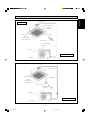
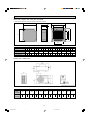
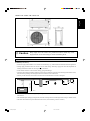
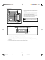
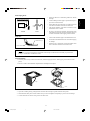
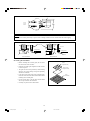
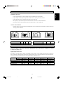
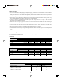
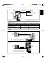
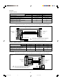
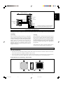
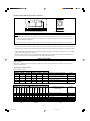
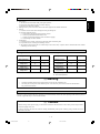
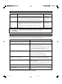
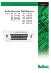
CEILING CASSETTE
SPLIT TYPE AIR CONDITIONER
INSTALLATION MANUAL
COVER-CK-20A
3
2/1/01, 10:34 AM
English
INSTALLATION MANUAL
This manual provides the procedures of installation to ensure a safe and good standard of operation for the air
conditioner unit.
Special adjustment may be necessary to suit local requirements.
Before using your air conditioner, please read this instruction manual carefully and keep it for future reference.
CEILING CASSETTE SPLIT TYPE AIR CONDITIONER
MODEL
COOLING ONLY
HEAT PUMP
CK20A / ACK20A / YCK20A
CK20AR / ACK20AR / MCK020AR / YCK20AR
SL20B / ALC20B / YSL20B
SL20BRK / ALC20BRK / MLC020BRK / YSL20BRK
CK25A / ACK25A / MCK025A / YCK25A
CK25AR / ACK25AR / MCK025AR / YCK25AR
SL25B / ALC25B / MLC025B / YSL25B
SL25BRK / ALC25BRK / MLC025BRK / YSL25BRK
CK30A / ACK30A / MCK030A / YCK30A
CK30AR / ACK30AR / MCK030AR / YCK30AR
SL30C / ALC30C / MLC30C / YSL30C
SL30CR / ALC30CR / MLC030CR / YSL30CR
CK40A / ACK40A / MCK040A / YCK40A
CK40AR / ACK40AR / MCK040AR / YCK40AR
SL40C / ALC40C / MLC040C / YSL40C
SL40CR / ALC40CR / MLC040CR / YSL40CR
CK50A / ACK50A / MCK050A / YCK50A
CK50AR / ACK50AR / MCK050AR / YCK50AR
SL50C / ALC50C / MLC050C / YSL50C
SL50CR / ALC50CR / MLC050CR / YSL50CR
IM-CKA-0400-1
Part No.:08019004666
1-1
CK20A(1-16)ENG
1
2/1/01, 10:15 AM
CONTENTS
- Safety Precautions
- Installation Diagram
- Outline And Dimensions
- Installation of Indoor Unit
- Installation Of Outdoor Unit
- Refrigerant Piping Work
- Electrical Wiring Connection
- Vacuuming and Charging
- Accessory Parts
- Indicator Lights
- Overall Checking
- Standard Operation Conditions
- Auto Random Re-start Function
- Service And Maintenance
- Trouble Shooting
page 02
page 03
page 04
page 5
page 09
page 9
page 10
page 13
page 13
page 14
page 15
page 15
page 15
page 16
page 16
SAFETY PRECAUTIONS
Before installing the air conditioner unit, please read the following safety precautions carefully.
! Warning
•
Installation and maintenance should be performed by qualified persons who are familiar with local code and
regulation, and experienced with this type of appliance.
•
All field wiring must be installed in accordance with the national wiring regulation.
•
Ensure that the rated voltage of the unit corresponds to that of the name plate before commencing wiring work
according to the wiring diagram.
•
The unit must be GROUNDED to prevent possible hazard due to insulation failure.
•
All electrical wiring must not touch the refrigerant piping or any moving parts of the fan motors.
•
Confirm that the unit has been switched OFF before installing or servicing the unit.
IMPORTANT
DO NOT INSTALL OR USE THE AIR CONDITIONER UNIT IN A LAUNDRY ROOM.
! Caution
Please take note of the following important points when installing.
• Do not install the unit where leakage of flammable gas may occur.
If gas leaks and accumulates around the unit, it may cause fire ignition.
• Ensure that the drainage piping is connected properly.
If the drainage piping is not connected properly, it may cause water leakage which will dampen the
furniture.
• Do not overcharge the unit.
This unit is factory pre-charged. Overcharge will cause over-current or damage to the compressor.
• Ensure that the units panel is closed after service or installation.
Unsecured panels will cause the unit to operate noisily.
1-2
CK20A(1-16)ENG
2
2/1/01, 10:15 AM
INSTALLATION DIAGRAM
English
Wireless Remote Control
Drain Hose
INDOOR UNIT
Air Discharge Louver
IR Receiver
LED Light
Front Panel
Air Intake Grille
Air Filter
(behind the grille)
Air Discharge Louver
Remote Control
Refrigerant Piping
Air Intake
Air Intake
OUTDOOR UNIT
Air Discharge
Wired Remote Control
Drain Hose
Air Discharge Louver
Front Panel
Air Intake Grille
Air Filter
(behind the grille)
Air Discharge Louver
Remote Control
Refrigerant Piping
Air Intake
Air Intake
OUTDOOR UNIT
Air Discharge
1-3
CK20A(1-16)ENG
3
2/1/01, 10:15 AM
OUTLINE AND DIMENSIONS
Indoor Unit : CK20A / 25A / 30A / 40A / 50A & AR
• (With Wireless Remote Control & With Wired Remote Control)
B
C
F
E
H
J
I
G
A
D
M
All dimensions are in mm.
MODEL
CK 20A/AR
CK 25A/AR
CK 30A/AR
CK 40A/AR
CK 50A/AR
A
B
C
D
E
F
G
H
I
J
K
820
820
363
335
28
930
930
642
622
555
555
Outdoor Unit : SL20B / 25B
L
D
C
A
B
E
K
G
J
I
H
F
All dimensions are in mm.
MODEL
SL20B /
SL20BRK
A
B
C
D
E
F
G
H
I
J
K
L
840
492
408
378
330
297
309
626
646
64
148.5
78.5
SL25B /
SL25BRK
1-4
CK20A(1-16)ENG
4
2/1/01, 10:15 AM
448.0
141.5
English
746.5
141.5
20.0
Outdoor Unit : SL30C / 40C / 50C & CR
40.0
400.0
320.0
40.0
850.0
20.0
1030.0
25.0
50.0
85.0
All dimensions are in mm.
! Caution
Sharp edges and coil surfaces are potential locations which may cause
injury hazards. Avoid from being in contact with these places.
INSTALLATION OF THE INDOOR UNIT
Preliminary Site Survey
• Electrical supply and installation is to conform to local authority's (e.g. National Electrical Board) codes and regulations.
• Voltage supply fluctuation must not exceed +10% of rated voltage. Electricity supply lines must be independent of
welding transformers which can cause high supply fluctuation.
• Ensure that the location is convenient for wiring, piping and drainage.
• The indoor unit must be installed in such that is free from any obstacles in path of cool air discharge and warm air return,
and must allow spreading of air throughout the room (near the center of the room).
Min. 0.5 m
Min. 0.5 m
Min. 0.5 m
Max. 0.3 m
Max. 3.0 m
Min. 1.0 m
Beam
• Must be provide clearance for the indoor unit from the wall and obstacles as shown in the figure.
Obstacle
Floor
• The installation place must be strong enough to support a load 4 times the indoor unit weight to avoid amplifying noise
and vibration.
• The installation place (hanging ceiling surface) must be assuring levelness and the height in the ceiling is 350mm or more.
• The indoor unit must be away from heat and steam sources (avoid installing it near an entrance).
1-5
CK20A(1-16)ENG
5
2/1/01, 10:15 AM
Unit Installation
890.0 mm (Ceiling board opening)
•
Measure and mark the position for the hanging rod. Drill
the hole for the angle nut on the ceiling and fix the
hanging rod.
•
The installation template is extended according to
temperature and humidity. Check on dimensions in use.
•
The dimensions of the installation template are the same
as those of the ceiling opening dimensions.
•
Before ceiling laminating work is completed, be sure to
fit the installation template to the indoor unit.
Unit
890.0 mm (Ceiling board opening)
Unit size 820.0 mm
Unit size 820.0 mm
620.5 mm (Hanging rod)
790.0 mm (Hanging rod)
NOTE
Be sure to discuss the ceiling drilling work with the
installers concerned.
Piping
Direction
Unit Hanging
Indoor Unit
Ceiling
Board
35.0 mm
• Confirm the pitch of the hanging rod is 790mm × 620.5mm sharp.
• Hold the unit and hang it on the hanging rod with the nut and washer.
• Adjust the unit height to 35.0 mm between the indoor unit bottom surface and the ceiling surface.
• Confirm with a level gauge that the unit is installed horizontally and tighten the nut and bolt to prevent unit falling
and vibration.
• Open the ceiling board along the outer edge of the paper installation template.
1-6
CK20A(1-16)ENG
6
2/1/01, 10:15 AM
Indoor Unit
Pipe Clamp
GOOD
BAD
•
Drain pipe must be in downward gradient for smooth
drainage.
•
Avoid installing the drain pipe in up and down slope to
prevent reversed water flow.
•
During the drain pipe connection, be careful not to exert
extra force on the drain connector at indoor unit.
•
The outside diameter of the drain connection at the
flexible drain hose is 20mm.
•
Be sure to execute heat insulation (polyethylene foam
with thickness more than 8.0mm) on the drain piping to
avoid the condensed water dripping inside the room.
•
Connect the main drain pipe to the flexible drain hose.
•
Feed water from flexible drain hose to check the piping
for leakage.
•
When the test is completed, connect the flexible drain
hose to the drain connector on the indoor unit.
Drain Test
Feed Water
Main Drain Pipe
Flexible Drain Hose
NOTE
This Indoor Unit uses a drain pump for condensed water drainage. Install the unit horizontally to prevent water
leakage or condensation around the air outlet.
Panel Installation
• The front panel can only be fitted in one direction, follow the piping direction. (Follow piping arrow sticker on front
panel)
• Be sure to remove the installation template before installing the front panel.
Open
Screw
• Open the air intake grille by pulling back the catchers and removing it together with filter from panel.
• Install the front frame panel onto the indoor unit by 4 screws and tighten it completely to prevent cool air leakage.
• Connect the LED wire and air swing wire to the indoor unit.
1-7
CK20A(1-16)ENG
7
2/1/01, 10:15 AM
English
Drain Piping Work
Control Box
LED Wire
From
Front
Panel
Air Swing
Wire
NOTE
Install the front frame panel firmly to prevent cool air leakage which will cause condensation and water dripping.
Indoor Unit
Cool
Air
Cool
Air
Air Leak
Air Leak
Ceiling Board
Ceiling Board
Panel
Panel
Bad Installation
Good Installation
Air intake grille installation
•
Before installing the air intake grille, be sure to fix
the ionizer filter to the air filter.
•
Install the air intake grille together with the air filter
to the front panel.
•
The grille can be fit in any direction, when selecting
direction, the ceiling design and grille operability
should be considered.
•
If the unit comes with ionizer filter (optional item),
make sure to fix the ionizer filter to the air filter before
installing the air intake grille.
•
Fix the ionizer filter to the air filter with the black
side on top and white side at bottom.
•
Carefully clip on the ionizer filter frame.
Frame
(Optional Item)
Ionizer Filter
(Optional Item)
Filter
(Standard)
1-8
CK20A(1-16)ENG
8
2/1/01, 10:15 AM
INSTALLATION OF OUTDOOR UNIT
•
A place protected from rain, direct sunlight and well-ventilated wherever practicable.
•
A place capable of bearing the weight of the outdoor unit and isolating noise and vibration.
•
A place where there are no obstruction of air flow into or out the unit.
•
Do not put any object which may become obstacle for the air flow into or out the outdoor unit.
•
The location must not be susceptible to high concentration dust, oil, salt or sulfide gas.
English
Preliminary site survey
Outdoor unit installation
•
Install the outdoor unit firmly and horizontally. Maintain a space clearance from the obstruction as shown in below for
servicing and air ventilation.
A
B
C
A
D
C
C
B
SL SERIES
A
B
C
D
MSS SERIES
A
B
C
MIN. DISTANCE (mm)
300
1000
300
500
MIN. DISTANCE (mm)
500
1000
500
REFRIGERANT PIPING WORK
Refrigerant piping is important in particular. Refrigeration cycle of the split air conditioner is realized
by the perfect piping work.
Piping length and elevation
If the piping is too long, both the capacity and reliability of unit will drop. As the number of bends increase, resistance to
flow of refrigerant system increases, thus lowering cooling capacity and as a result the compressor may become defective.
Always choose the shortest path and follow the recommendation as tabulated below.
MODEL
INDOOR
OUTDOOR
MAX. LENGTH (M)
MAX. ELEVATION (M)
MAX. NO. OF BENDS
LIQUID PIPE SIZE
GAS PIPE SIZE
CK20A/AR
SL20B/BRK
15 m
8m
10
1/4”
5/8”
CK25A/AR
SL25B/BRK
15 m
8m
10
3/8”
5/8”
CK30A/AR
SL30C/CR
20 m
10 m
10
3/8”
5/8”
1-9
CK20A(1-16)ENG
9
2/1/01, 10:15 AM
CK40A/AR
SL40C/CR
20 m
10 m
10
3/8”
3/4”
CK50A/AR
SL50C/CR
20 m
10 m
10
3/8”
3/4”
Piping Connection
•
Do not use contaminated or damaged copper tubing. If any piping, evaporator or condenser had been exposed or had been
opened for 15 seconds or more, then vacuum and purge with field supplied refrigerant. Generally, do not remove plastic,
rubber plugs and brass nuts from the valves, fittings, tubing and coils until it is ready to connect suction or liquid line into
valves or fittings.
•
If any brazing work is required, ensure that nitrogen gas is passed through coil and joints while the brazing work is being
done. This will eliminate soot formation on the inside wall of copper tubings.
•
Cut the pipe stages by stages, advancing the blade of pipe cutter slowly. Extra force and a deep cut will cause more
distortion of pipe and therefore extra burr.
•
Remove burrs from cut edges of pipes with a remover. This will avoid unevenness on the flare face which will cause gas
leak.
•
Align the center of the piping and sufficiently tighten the flare nut with fingers. Finally, tighten the flare nut with torque
wrench until the wrench clicks.
•
Be sure to execute heat insulation. (polyurethane form with thickness more than 15 mm)
•
Except the outdoor unit which is pre-charge with refrigerant R22, the indoor unit and the refrigerant connection pipes must
be purged because the air that contain moisture remaining in the refrigerant cycle may cause malfunction to the compressor.
Additional Charge
The refrigerant is pre-charge in the outdoor unit, but additional charge of refrigerant after vacuuming is necessary. Follow
the recommendation as tabulated below.
Cooling Only
MODEL
INDOOR
OUTDOOR
CK20A
SL20B
0.250 kg
0.280 kg
0.325 kg
0.400 kg
-
L <= 5 m
L=7m
L = 10 m
L = 15 m
L = 20 m
CK25A
SL25B
0.100 kg
0.176 kg
0.290 kg
0.480 kg
-
CK30A
SL30C
0.400 kg
0.600 kg
0.650 kg
0.900 kg
1.150 kg
CK40A
SL40C
0.100 kg
0.250 kg
0.500 kg
0.750 kg
CK50A
SL50C
0.100 kg
0.250 kg
0.500 kg
0.750 kg
Heat Pump
MODEL
INDOOR
OUTDOOR
L <= 5 m
L=7m
L = 10 m
L = 15 m
L = 20 m
CK20AR
SL20BRK
0.050 kg
0.075 kg
0.150 kg
-
CK25AR
SL25BRK
0.100 kg
0.500 kg
0.750 kg
-
CK30AR
SL30CR
0.100 kg
0.250 kg
0.500 kg
0.750 kg
CK40AR
SL40C
0.100 kg
0.250 kg
0.500 kg
0.750 kg
CK50AR
SL50C
0.100 kg
0.250 kg
0.500 kg
0.750 kg
ELECTRICAL WIRING CONNECTION
Cooling Only
CK20A / CK25A & CK30A
MODEL
INDOOR
OUTDOOR
CK20A
CK25A
SL20B
SL25B
220 - 240V / 1ph / 50Hz +
2.5
2.5
3
3
2.5
2.5
3
3
VOLTAGE RANGE
POWER SUPPLY CABLE SIZE (mm2)
NUMBER OF CONDUCTORS
INTERCONNECTION CABLE SIZE (mm2)
NUMBER OF CONDUCTORS
1-10
CK20A(1-16)ENG
10
2/1/01, 10:15 AM
Interconnection Cable
COMP
COMP
L
Indoor Unit
Terminal
Block
N
N
Outdoor Unit
Terminal
Block
N
Power Supply Cable
!
CK20A / 25A / 30A
<> SL20B / 30B
There must be a double pole switch with minimum
3mm contact gap and fuse/circuit breaker as
recommended in the fixed installation circuit.
CK30A / CK40A & CK50A
MODEL
INDOOR
OUTDOOR
VOLTAGE RANGE
POWER SUPPLY CABLE SIZE (mm2)
NUMBER OF CONDUCTORS
INTERCONNECTION CABLE SIZE (mm2)
NUMBER OF CONDUCTORS
IMPORTANT :
CK30A
SL30C
220 - 240V / 1ph / 50Hz +
4
3
1.5
4
CK40A
CK50A
SL40C
SL50C
380-420V /3ph /50Hz +
2.5
2.5
5
5
1.5
1.5
4
4
These values are for information only. They should be checked and selected to comply with local and/or
national codes and regulations. They are also subject to the type of installation and size of conductors.
CK30A <> SL30C
COMP
Indoor Unit
Terminal
Block
Interconnection Cable
COMP
L
L
N
N
Outdoor Unit
Terminal
Block
L
!
There must be a double pole switch with minimum
3mm contact gap and fuse/circuit breaker as
recommended in the fixed installation circuit.
Power Supply Cable
CK40A / CK50A <>
SL40C / SL50C
N
COMP
L
N
COMP
Indoor Unit
Terminal
Block
L
N
R
Interconnection Cable
S
Outdoor Unit
Terminal
Block
T
N
!
There must be a double pole switch with minimum
3mm contact gap and fuse/circuit breaker as
recommended in the fixed installation circuit.
Power Supply Cable
1-11
CK20A(1-16)ENG
11
2/1/01, 10:15 AM
English
IMPORTANT : These values are for information only. They should be checked and selected to comply with local and/or
national codes and regulations. They are also subject to the type of installation and size of conductors.
Heat Pump
CK20AR / CK25AR
MODEL
INDOOR
OUTDOOR
CK20AR
CK25AR
SL20BRK
SL25BRK
220 - 240V / 1ph / 50Hz +
2225 / 1940
2937 / 2435
11.48 / 10.35
14.0 / 12.40
2.5
2.5
3
3
2.5
2.5
5
5
VOLTAGE RANGE
POWER INPUT (cooling/heating), W
RATED CURRENT (cooling/heating), A
POWER SUPPLY CABLE SIZE (mm2)
NUMBER OF CONDUCTORS
INTERCONNECTION CABLE SIZE (mm2)
NUMBER OF CONDUCTORS
IMPORTANT : These values are for information only. They should be checked and selected to comply with local and/or
national codes and regulations. They are also subject to the type of installation and size of conductors.
CK20AR / 25AR <> SL20BRK / 25BRK
Outdoor Coil Sensor
4WV
Indoor Unit
Terminal
Block
4V
Interconnection Cable
OF
OF
COMP
COMP
L
N1
Outdoor Unit
Terminal
Block
N
N2
Power Supply Cable
!
There must be a double pole switch with minimum
3mm contact gap and fuse/circuit breaker as
recommended in the fixed installation circuit.
CK30AR / CK40AR & CK50AR
INDOOR
OUTDOOR
MODEL
VOLTAGE RANGE
POWER SUPPLY CABLE SIZE (mm2)
NUMBER OF CONDUCTORS (1)
INTERCONNECTION CABLE SIZE (mm2)
NUMBER OF CONDUCTORS (1)
CK30AR
SL30CR
220-240V/1ph/50Hz +
4
3
1.5
7
CK40AR
CK50AR
SL40CR
SL50CR
380 - 420V / 3ph / 50Hz +
2.5
2.5
5
5
1.5
1.5
7
7
IMPORTANT : These values are for information only. They should be checked and selected to comply with local and/or
national codes and regulations. They are also subject to the type of installation and size of conductors.
CK30AR <>
SL30CR
Outdoor Coil Sensor
Indoor Unit
Terminal
Block
!
A
A
4WV
4WV
Interconnection
Cable
OF
COMP
COMP
L
L
N
N
There must be a double pole switch with minimum
3mm contact gap and fuse/circuit breaker as
recommended in the fixed installation circuit.
Power
Supply
Cable
1-12
CK20A(1-16)ENG
12
OF
2/1/01, 10:15 AM
L
N
Outdoor Unit
Terminal
Block
CK40AR / CK50AR <> SL40CR / SL50CR
English
Outdoor Coil Sensor
A
4WV
OF
Outdoor
Unit
Terminal
COMP
L
A
4WV
Indoor Unit
Terminal
Block
N
Interconnection
Cable
OF
R
COMP
S
L
T
N
N
Power
Supply
Cable
!
There must be a double pole switch with minimum
3mm contact gap and fuse/circuit breaker as
recommended in the fixed installation circuit.
VACUUMING AND CHARGING
Vacuuming is necessary to eliminate all moisture and air from the system. The series II Outdoor Unit is provided with flare
valve fittings.
Vacuuming
Charging
Before vacuuming, perform leak check for refrigeration
circuit. After the system piping are properly connected,
connect the flexible hoses to the correct charging nipples
as shown in the diagram. Ensure that flexible hose from
charging nipples are connected to the vacuum pump via
standard servicing valves and pressure gauges (gauge
manifold). Vacuum the air conditioner system to at least
500 microns Hg. Do not start the unit when the system is
engaged in vacuuming.
Before charging, the vacuum must be held at 500 microns
Hg for at least 15 minutes, then break vacuum by charging
R-22 refrigerant. Operate the unit for 15 minutes and ensure
the refrigerant charges is of correct by monitoring running
current, gas and liquid line pressures. Suction and discharge
pipe pressure should be in the region of 75 psig and 275
psig generally.
After ensuring the system is correctly charged, remove
flexible hose from charging nipples and replace caps.
ACCESSORY PART
Short Duct Specification
• The indoor unit is provided with air discharge and air intake “knock-out” hole for duct connection. However the connection of the short duct for air discharge is possible on only one side.
• The use of short duct for air discharge will improve airflow distribution if there is an obstruction (such as a lighting fixture)
or in a long, narrow room or an L-shaped room. It also use for air conditioning of two rooms simultaneously.
Possible Direction For Air Discharge And Air Intake
Air Discharge
Air Discharge
Air Intake
Air Discharge
Air Discharge
1-13
CK20A(1-16)ENG
13
2/1/01, 10:15 AM
Possible Opening Dimension For Duct Connection
PCD fl140
50
50
50
50
50
10
20
10
20
70
90
fl100
115
109
20
119
115
Air Intake Knock Out Hole
Air Discharge Knock Out Hole
NOTE
• Avoid using the short duct on which the air discharge grille can be completely closed, to prevent evaporator freezing.
• In order to prevent condensation forming, be sure that there is sufficient thermal insulation and no leakage of cool
air when installing the short duct.
• Keep the introduction of fresh air intake within 20% of total air flow. Also provide a chamber and use a booster fan.
Sealing Material
• It is possible to seal one of the four air discharge outlet. (sealing two or more air discharge outlet could cause a malfunction)
• Remove the front panel and insert the sealing material into the air discharge outlet on the indoor unit to seal the air outlet.
• The sealing material is the same length as the longer air discharge outlet. If it is desired to seal the shorter air discharge
outlet, cut the sealing material to shorten it.
• Push the sealing material in about 10 mm beyond the bottom surface of the indoor unit so that it does not touch the air
louver. Be sure not to push the sealing material in any farther than about 10 mm.
INDICATOR LIGHTS
Remote Control
When there is infrared remote control operating signal, the signal receiver on indoor unit will make a <beep> for signal
acceptance confirmation.
Operating State And Fault Table
Wireless Remote Control
COOLING
HEAT PUMP
POWER TIMER
SLEEP POWER TIMER
HEAT
/
/
/
/
OPERATION / FAULTY INDICATION
ACTION
Power ON
-
Room/Indoor/Outdoor (heat pump) Coil
Call Your Dealer
Sensor Contact Loose/Short
Gas Leak Faulty/Compressor Overload
Call Your Dealer
Condensate Water Overflow
Call Your Dealer
Outdoor Defrost (heat pump only)
Wired Remote Control
COOLING
H M L C
S
I
G
H
E
D
O
W
O
O
L
L
E
E
P
T
H
M
L
I
M
E
R
I
G
H
E
D
O
W
HEAT PUMP
C S
T
O
O
L
L
E
E
P
I
M
E
R
H
E
A
T
OPERATION / FAULTY
INDICATION
Room Sensor Contact Loose/Short
Indoor Coil Sensor Contact Loose/Short
Outdoor Coil Sensor Contact Loose/Short
Gas Leak Faulty
Compressor Overload
Condensate Water Overflow
Outdoor Defrost (heat pump only)
ON
/
ON OR OFF
14
Call Your Dealer
Call Your Dealer
Call Your Dealer
Call Your Dealer
Call Your Dealer
Call Your Dealer
Call Your Dealer
BLINKING
1-14
CK20A(1-16)ENG
ACTION
2/1/01, 10:15 AM
• Ensure that :1) The unit has been mounted solidly and rigid in position.
2) Piping and connections are leak proof after charging.
3) Proper wiring has been installed.
• Drainage check - pour some water into the main drain pipe from the flexible drain hose.
• Test run
1) Conduct a test run after water drainage test and gas leakage test.
2) Check the following items :a. Is the electric plug firmly inserted into the socket ?
b. Is there any abnormal sound from the unit ?
c. Is there any abnormal vibration on the unit itself or piping ?
d. Is the drainage of water smooth ?
• Confirm that :
1) Condenser fan is running, with warm air blowing off the condensing unit.
2) Evaporator blower is running and discharge cool air.
3) The remote control incorporate a 3 minute delay in the circuit. Thus, it requires about 3 minutes before the outdoor
condensing unit can start up.
STANDARD OPERATION CONDITIONS
Heating
Cooling
Temperature
Minimum indoor
temperature
Maximum indoor
temperature
Minimum outdoor
temperature
Maximum outdoor
temperature
TsoC
ThoC
16
11
32
23
16
11
43
26
Temperature
Minimum indoor
temperature
Maximum indoor
temperature
Minimum outdoor
temperature
Maximum outdoor
temperature
TsoC
ThoC
16
-
30
-
-5
-6
24
18
Ts : Dry bulb temperature.
Th : Wet bulb temperature.
! Warning
•
•
Disconnect from the main power supply before servicing the air conditioner unit.
DO NOT pull out the power cord when the power is ON. This may cause serious electrical shocks which
may result in fire hazards.
AUTO RANDOM RE-START FUNCTION
If there is a power cut when the unit is operating, it will automatically resume the same operating mode when the power is
restored. (Applicable only to units with this feature)
! Caution
Before turning off the power supply, set the remote controller's ON/OFF switch to the “OFF” position to prevent the
nuisance tripping of the unit.
If this is not done, the unit's fans will start turning automatically when power resumes, posing a hazard to service
personnel or the user.
1-15
CK20A(1-16)ENG
15
2/1/01, 10:15 AM
English
OVERALL CHECKING
SERVICE AND MAINTENANCE
SERVICE PARTS
Indoor air filter
Indoor unit
MAINTENANCE PROCEDURES
PERIOD
1. Remove any dust adhered on the filter by using a vacuum cleaner or
wash in lukewarm water (below 40oC) with neutral cleaning detergent.
At least once
every 2 weeks.
2. Rinse well and dry the filter before placing it back onto the unit.
More frequently if
3. Do not use gasoline, volatile substances or chemical to clean the filter.
necessary.
1. Clean any dirt or dust on the grille or panel by wiping it using soft
cloth soaked in lukewarm water (below 40oC) with neutral detergent
solution.
At least once
every 2 weeks.
2. Do not use gasoline, volatile substances or chemical to clean the
indoor unit.
More frequently if
necessary.
! Caution
Do not operate any heating apparatus too close to the air conditioner unit. This may cause
the plastic panel to melt or deform as a result of the excessive heat.
TROUBLE SHOOTING
If any malfunction of the air conditioner unit is noted, immediately switch off the power supply to the unit.
Check the following fault conditions and causes for some simple trouble shooting tips.
FAULT
CAUSES / ACTION
1. The compressor does not start operate after 3 minutes
from starting the air conditioner unit.
- Protection against frequent starting. Wait for 3 to 4
minutes for the compressor to start operating.
2. The air conditioner unit does not operate.
- Power failure, or the fuse need to be replaced.
- The power plug is disconnected.
- It is possible that your delay timer has been set incorrectly.
- If the fault persist after all these verifications, please
contact the air conditioner unit installer.
3. The air flow is too low.
- The air filter is dirty.
- The doors or windows are open.
- The air suction and discharge are clogged.
- The regulated temperature is not high enough.
4. Discharge air flow has bad odor.
- Odors may be caused by cigarettes, smoke particles,
perfume etc. which might have adhered onto the coil.
5. Condensation on the front air grille of the indoor unit.
- This is caused by air humidity after an extended long
period of operation.
- The set temperature is too low, increase the temperature
setting and operate the unit at high fan speed.
6. Water flowing out from the air conditioner unit.
- Switch off unit and call dealer.
7. Hissing air flow sound from the air conditioner unit
during operation.
- Refrigerant fluid flowing into the evaporator coil.
If the fault persists, please call your local dealer / serviceman.
1-16
CK20A(1-16)ENG
16
2/1/01, 10:15 AM
•
In the event that there is any conflict in the interpretation of this manual and any translation of the same in any language,
the English version of this manual shall prevail.
•
The manufacturer reserves the right to revise any of the specification and design contain herein at any time without prior
notification.
•
En cas de désaccord sur l’interprétation de ce manuel ou une de ses traductions, la version anglaise fera autorité.
•
Le fabriquant se réserve le droit de modifier à tout moment et sans préavis la conception et les caractéristiques techniques
des appareils présentés dans ce manuel.
•
Im Falle einer widersprüchlichen Auslegung der vorliegenden Anleitung bzw. einer ihrer Übersetzungen gilt die Ausführung
in Englisch.
•
Änderungen von Design und technischen Merkmalen der in dieser Anleitung beschriebenen Geräte bleiben dem Hersteller
jederzeit vorbehalten.
•
Nel caso ci fossero conflitti nell’interpretazione di questo manuale o delle sue stesse traduzioni in altre lingue, la versione
in lingua inglese prevale.
•
Il fabbricante mantiene il diritto di cambiare qualsiasi specificazione e disegno contenuti qui senza precedente notifica.
•
En caso de conflicto en la interpretación de este manual, y en su traducción a cualquier idioma, prevalecerá la versión
inglesa.
•
El fabricante se reserva el derecho a modificar cualquiera de las especificaciones y diseños contenidos en el presente
manual en cualquier momento y sin notificación previa.
•
В случае противоречия перевода данного руководства с другими переводами одного и того же текста,
английский вариант рассматривается как приоритетный.
•
Завод-изготовитель оставляет за собой право изменять характеристики и конструкцию в любое время
без предварительного уведомления.
OYL MANUFACTURING COMPANY SDN. BHD.
JALAN PENGAPIT 15/19, P.O. BOX 7072, 40702 SHAH ALAM, SELANGOR DARUL EHSAN, MALAYSIA.
COVER-CK-20A
2
2/1/01, 10:34 AM