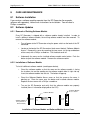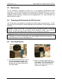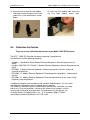
1
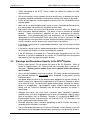
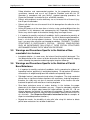
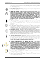
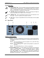
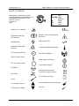
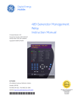
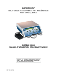
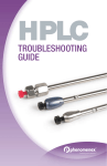
RITA® 1500X USER’S GUIDE AND SERVICE MANUAL (For software version 8.60 and above) Caution: Federal U.S. Law restricts this device to sale by or on the order of a physician. 160-103990 Rev 03 AngioDynamics, Inc. Model 1500X User’s Guide and Service Manual Table of Contents 1. INTRODUCTION AND GENERAL INFORMATION ............................................................................ 2 2. SYSTEM DESCRIPTION ...................................................................................................................... 3 3. WARNINGS AND PRECAUTIONS ...................................................................................................... 4 3.1 3.2 3.3 3.4 3.5 3.6 4. SWITCHES, BUTTONS, CONNECTIONS, AND DISPLAYS .............................................................. 7 4.1 4.2 5. FRONT PANEL ................................................................................................................................................. 7 REAR PANEL .................................................................................................................................................. 9 INSTRUCTIONS FOR USE OF THE GENERATOR .......................................................................... 10 5.1 6. GENERAL W ARNINGS AND PRECAUTIONS .......................................................................................................... 4 ENVIRONMENTAL AND EMI W ARNINGS AND PRECAUTIONS .................................................................................. 4 W ARNINGS AND PRECAUTIONS DURING ELECTROSURGICAL DEVICE USE .............................................................. 4 W ARNINGS AND PRECAUTIONS SPECIFIC TO THE RITA SYSTEM ........................................................................ 5 W ARNINGS AND PRECAUTIONS SPECIFIC TO THE ABLATION OF NON-RESECTABLE LIVER LESIONS ........................... 6 W ARNINGS AND PRECAUTIONS SPECIFIC TO THE ABLATION OF PAINFUL BONE METASTASES .................................. 6 STEPS IN THE PROCEDURE............................................................................................................................. 10 5.1.1 Patient Preparation ...................................................................................................................... 10 5.1.2 Setting up the RF Generator ........................................................................................................ 11 5.1.3 Programming the RF Generator and Connecting the Devices/Accessories ................................. 11 5.1.4 Operation of the RF Generator During a Procedure .................................................................... 11 5.1.5 Disposal ....................................................................................................................................... 12 DESCRIPTIONS OF MODES OF OPERATION ................................................................................ 13 6.1 6.2 6.3 6.4 6.5 6.6 6.7 6.8 6.9 STANDBY MODE: ........................................................................................................................................... 13 READY MODE: .............................................................................................................................................. 13 PURGE MODE: .............................................................................................................................................. 13 RF ON MODE: .............................................................................................................................................. 13 RF OFF MODE: ............................................................................................................................................. 13 AUTOMATIC TEMPERATURE CONTROL (ATC) MODE: ........................................................................................ 13 6.6.1 ATC Mode for Dry Devices .......................................................................................................... 14 6.6.2 ATC Mode for Infusion Devices ................................................................................................... 14 COOL DOWN MODE: ...................................................................................................................................... 14 TRACK ABLATION MODE: ............................................................................................................................... 14 BIPOLAR MODE: ............................................................................................................................................ 15 7. CLINICAL STUDIES ........................................................................................................................... 15 8. CARE AND MAINTENANCE ............................................................................................................. 16 8.1 8.2 8.3 8.4 8.5 8.6 9. SOFTWARE INSTALLATION .............................................................................................................................. 16 SOFTWARE UPDATES .................................................................................................................................... 16 8.2.1 Removal of Existing Software Module ......................................................................................... 16 8.2.2 Installation of Software Module .................................................................................................... 16 MAINTENANCE .............................................................................................................................................. 17 CLEANING AND DISINFECTING THE RF GENERATOR .......................................................................................... 17 FUSE REPLACEMENT ..................................................................................................................................... 17 CALIBRATION VERIFICATION ........................................................................................................................... 18 SPECIFICATIONS .............................................................................................................................. 19 9.1 RF GENERATOR SPECIFICATIONS ................................................................................................................... 19 10. TROUBLESHOOTING........................................................................................................................ 24 10.1 RF GENERATOR LCD TROUBLESHOOTING MESSAGES ..................................................................................... 24 10.1.1 Self Test Troubleshooting Messages ........................................................................................... 24 10.1.2 Troubleshooting Messages During Use ....................................................................................... 25 10.1.3 Impede-Out Recovery Routine..................................................................................................... 27 10.1.4 Device Troubleshooting ............................................................................................................... 27 WARRANTY ............................................................................................................................................... 28 160-103990 Rev 03 Page 1 AngioDynamics, Inc. 1. Model 1500X User’s Guide and Service Manual INTRODUCTION AND GENERAL INFORMATION AngioDynamics, Inc. is dedicated to providing service and support to its customers. If there are any questions concerning the use of the RITA System, please contact your local sales representative/distributor. If you are unable to reach them please contact Customer Service at one of the following: United States: Authorized European Representative: AngioDynamics, Inc. One Horizon Way Manchester, GA 31816 USA AngioDynamics UK Ltd. Building 2000, Beach Drive, IQ Cambridge, Waterbeach, Cambridge, CB25 9TE United Kingdom Toll Free: + 1-800-772-6446 Telephone: + 1-518-798-1215 Fax: + 1-518-798-1360 Telephone: Fax: 160-103990 Rev 03 +44 (0)122-372-9361 +44 (0)122-372-9329 Page 2 AngioDynamics, Inc. 2. Model 1500X User’s Guide and Service Manual SYSTEM DESCRIPTION Indications for Use The AngioDynamics, Inc. Model 1500X Electrosurgical Radiofrequency Generator is designed to provide monopolar radiofrequency (RF) energy to be used for coagulation and ablation of soft tissue. The Model 1500X Electrosurgical Radiofrequency Generator is indicated for use in percutaneous, laparoscopic, or intraoperative coagulation and ablation of soft tissue, including • the partial or complete ablation of non-resectable liver lesions, and • the palliation of pain associated with metastatic lesions involving bone in patients who have failed or are not candidates for standard pain therapy. Products and Components The Model 1500X Electrosurgical Radiofrequency Generator is capable of delivering up to 250 W of RF power. The maximum available power is limited through software control. The generator is specifically designed for use with RITA Electrosurgical Devices. It has multiple temperature displays as well as efficiency and power displays to assist the physician in monitoring and controlling the ablation throughout the process. The RITA System consists of the following components: • Model 1500X Electrosurgical RF Generator (RF Generator): Provides RF energy to the RITA family of Devices through the Main Cable. Any equipment not manufactured by AngioDynamics (RITA ) should not be used with the Generator, because of the potential hazard it poses to the user, patient, and generator. • Disposable Electrosurgical Device (Device): The Model 1500X Generator is compatible with the RITA family of Devices. Please go to http://www.angiodynamics.com/pages/products/index.asp#. • Main Cable for the Device: Connects the Device to the RF Generator. Use the Main Cable provided with the Model 1500X RF Generator or the Device. • Dispersive Electrode: Provides the return path for the RF energy applied by the Device. Use only dispersive electrodes approved by AngioDynamics, Inc. If the Dispersive Electrodes have temperature monitoring (ThermoPads), they are connected to the generator at the RETURN port and at the AUX port and display the temperature readings in the Auxiliary Temperatures windows “A” and “B”. • Power Cord: Generator. • Foot Pedal: Pneumatic foot pedal used to turn RF energy on and off, and also to start and stop the purge operation when using the RF Generator with an infusion pump. Use the foot pedal provided with the Model 1500X RF Generator. • IntelliFlow Infusion Pump: The IntelliFlow Infusion Pump is used to deliver saline through the Infusion Device during ablation. Tubing is connected to the Infusion Device and loaded into the Infusion Pump. The RF Generator is connected to the Infusion Pump via an RS-232 cable. A line cord (medical grade, where applicable) that provides AC power to the RF 160-103990 Rev 03 Page 3 AngioDynamics, Inc. Model 1500X User’s Guide and Service Manual 3. WARNINGS AND PRECAUTIONS 3.1 General Warnings and Precautions 3.2 3.3 • Read all instructions for use for the RITA System prior to its use. Safe and effective electrosurgery is dependent not only on equipment design but also on factors under control of the operator. It is important that the instructions supplied with this equipment be read, understood, and followed in order to enhance safety and effectiveness. • For use only by qualified medical personnel trained in the safe use of electrosurgery and in the proper use of the RITA System. Environmental and EMI Warnings and Precautions • In the case of a pacemaker, a theoretical hazard exists because interference with the action of the pacemaker may occur, and the pacemaker may become damaged or may reset to its factory default. Questions should be directed to the attending Cardiologist, or to the pacemaker manufacturer, and it is recommended that the patient see a cardiologist after the procedure to verify functionality of the pacemaker. • Any monitoring electrodes should be placed as far as possible from the RITA Device and should incorporate high-frequency current limiting devices. • Do not use flammable anesthetics, gases, or liquids while the RF Generator is in use. The risk of igniting flammable gases or other materials is inherent in electrosurgery and cannot be eliminated by device design. Precautions must be taken to avoid contact of flammable materials and substances with electrosurgical electrodes, whether they are in the form of an anesthetic or skin preparation agent, or produced by natural processes within body cavities, or originate in surgical drapes, tracheal tubes or other materials. • Interference produced by operation of high-frequency surgical equipment may adversely affect the operation of other electronic medical equipment such as monitors and imaging systems. This can be minimized or resolved by rearranging monitoring device cables so they do not overlap the RITA System cables. • Electric shock hazard. Do not saturate the RF Generator with liquids. Do not allow liquids to run inside the unit. Do not immerse the RF Generator in water. Shut off the RF Generator and disconnect power before cleaning. Do not sterilize the RF Generator. Warnings and Precautions during Electrosurgical Device Use • Precautions during ablation near organ surface or near vasculature – Due to the nonhomogenous conduction and convection of heat in this type of anatomy, shapes of ablations performed on tissue that is near the organ surface or near vasculature may not be spherical. Careful planning should be done for targets that require ablation in these locations. Any application or procedure that alters tissue perfusion and affects temperature elevation should be monitored carefully. • Any application or procedure that alters tissue perfusion and affects temperature elevation should be monitored carefully. If a Bair Hugger® or another warming device is used, turn it off prior to the ablation as this may constrict blood flow and elevate the temperature. If leg/circulation compressors are used, use calf-length devices, so that there is no overlap with the ThermoPads. 160-103990 Rev 03 Page 4 AngioDynamics, Inc. 3.4 Model 1500X User’s Guide and Service Manual • Cables connected to the RITA Device should not contact the patient or other electrical leads. • Skin-to-skin contact, such as between the torso and the arms, or between the legs of the patient should be avoided by insulating these contacts with sheets or dry towels. • Failure of high frequency surgical equipment could result in an unintended increase of output power. • When not in use electrosurgical leads (active or return) should be positioned so that they cannot come into contact with the patient or other leads. • High power settings can cause local desiccation of tissue, which can impede the ability to produce expected ablations. Set power as low as possible for intended purpose. Follow manufacturer’s guidelines of time at temperature for ablation generation. If the recommended times and temperatures are not achieved at full deployment of the Electrosurgical Device array, there can be no assurance that the desired ablation volume has been created. Standard evaluative techniques, e.g., CT or MRI, should be used to determine the actual extent of the ablation. • If the device is being used in a laparoscopic procedure, care must be taken to avoid a gas embolism. • If the device is being used in a laparoscopic procedure, activation of the device when not in contact with target tissue may cause capacitive coupling. • If the RF Generator shuts down for a ThermoPad over temperature error or if the generator is shut off or rebooted for any reason, the ThermoPads must be replaced and moved at least 4cm from their original location. Warnings and Precautions Specific to the RITA System • Electric shock hazard. Do not remove the cover of the RF Generator. Refer all service to AngioDynamics, Inc. There are no user-serviceable parts inside the RF Generator. Warranty will be voided if the unit is opened and/or the warranty seal is broken. • Only use metal introducers that have insulation. RF energy can be transmitted from the electrode through the un-insulated metal introducer to the patient causing inadvertent burns. • Low power output or failure of the electrosurgical equipment to function correctly at normal settings may indicate faulty application of the Dispersive Electrode or failure of an electrical lead. Do not increase power output before checking for obvious defects or misapplication. For monopolar surgery, effective contact between the patient and the Dispersive Electrode must be verified whenever the patient is repositioned. • Although accessories may have similar connector types, potentially hazardous conditions may exist when inappropriate accessories are combined, and may cause harm to the patient, user, or Generator. Therefore, it is essential that ONLY RITA Electrosurgical Devices and accessories are used with RITA RF Generators, and there is proper connection between them. • Reusable accessory cables should be periodically tested for function and safety in accordance with the cable’s instructions. • The use and proper placement of a Dispersive Electrode is a key element in the safe and effective use of monopolar electrosurgery, particularly in the prevention of burns. 160-103990 Rev 03 Page 5 AngioDynamics, Inc. Model 1500X User’s Guide and Service Manual Follow directions and recommended practices for the preparation, placement, surveillance, removal and use of any Dispersive Electrode used with this RF Generator in accordance with your facility’s standard operating procedure, the Dispersive Electrode’s Instruction for Use, and AAMI standards. 3.5 • Patients with peripheral vascular deficiency are at increased risk of thermal injury from Dispersive electrodes. • Patients with frail skin are at increased risk of skin damage from the adhesive on the Dispersive pads. • Having RF power on at the same time as infusion, using a method different from the instructions in this document and accompanying the Disposable Electrosurgical Device, may alter the path of the electrical energy away from target tissues. • It is important to carefully evaluate all candidates for this procedure for proximity of the intended ablation site to critical structures. As with all electrosurgical procedures, there is a risk of injuring adjacent structures. Ensure that device placement is at least 1 cm away from structures not intended for ablation. PROXIMITY TO NERVE STRUCTURES IS PARTICULARLY CRITICAL. SERIOUS COMPLICATIONS SUCH AS INCONTINENCE CAN OCCUR IF THESE CRITICAL STRUCTURES ARE DAMAGED DURING THE RF ABLATION PROCEDURE. Warnings and Precautions Specific to the Ablation of Nonresectable Liver Lesions • 3.6 Incomplete ablation – In some cases, the lesion will only be partially destroyed. The final determination of the success of lesion destruction can only be made by imaging studies following the procedure and during regular long-term follow-up. Warnings and Precautions Specific to the Ablation of Painful Bone Metastases • It is important to carefully evaluate all candidates for this procedure for evidence of impending fracture, particularly in weight-bearing bone. Do not perform RF ablation of metastases in weight-bearing bone with evidence of impending fracture. • Pathologic fracture is more prevalent and serious in long bone. The study conducted did not have a significant number of patients with metastases involving long bones; therefore, the study may not give an accurate estimate of the fracture rate after treatment for patients with metastases involving long bone. • Since bone metastases occur at various locations in the skeleton, the proper placement of the dispersive electrodes may vary. Dispersive electrodes should be oriented with the longest edge toward the target ablation site with 25 – 50 cm distance between the ablation site and dispersive electrodes. Dispersive electrodes should be equivalent distances from the active electrode in order to minimize the risk of a skin burn. (See Dispersive Electrode’s Instruction for Use for examples of dispersive electrode placement locations.) • Beyond four weeks, the durability of pain relief after using this device to ablate painful bone metastases has not been established. 160-103990 Rev 03 Page 6 AngioDynamics, Inc. Model 1500X User’s Guide and Service Manual 4. SWITCHES, BUTTONS, CONNECTIONS, AND DISPLAYS 4.1 Front Panel Switches and Buttons: 1. “RF ON/OFF” Button. Pressing this button turns the RF energy ON and OFF. 1. “RF ON/OFF” LED. A blue light-emitting diode (LED) that flashes once a second when the system is in Ready mode. When RF energy is turned on, this LED stays on continuously. 2. “TRACK ABLATION ON/OFF” (cauterization/coagulation) Button. Pressing this button, switches the system in and out of Track Ablation mode. 2. “TRACK ABLATION ON/OFF” (cauterization/coagulation) LED. A green LED that is off when this mode is not selected, flashing when the mode is selected, and is on continuously when the mode is active. 3. “CONTROL MODE” Button. Pressing this button sets the mode of operation. 4. “SET TEMP (°C)” Display. Displays the target temperature in whole units of °C. 4. “SET TEMP (°C)”Buttons. Pressing the arrow buttons sets the target temperature the system will try to achieve and maintain during the ablation. Temperature can be increased and decreased. (Note: If the target temperature is not reached within 30 minutes from the start of the RF energy delivery, the RF power automatically turns off.) 5. “SET POWER (W)” Display. Displays the maximum power setting in whole units of Watts. 5. “SET POWER (W)” Buttons. Pressing the arrow buttons sets the maximum power in whole units of Watts that the system will deliver during the ablation. The 160-103990 Rev 03 Page 7 AngioDynamics, Inc. Model 1500X User’s Guide and Service Manual power can be increased and decreased. (Note: Set power as low as possible for intended purposes.) 6. “DELIVERED POWER (W)” Display. Displays the actual power being delivered in whole units of Watts. 7. “TIMER (min)” Display. Displays the time to a resolution of 0.1 minutes. This display, prior to the start of the RF energy, shows the time set for RF energy delivery at the target temperature. Once the RF energy starts, the display shows the remaining time of RF energy delivery at the set temperature. If the Device temperature is not maintained at the target temperature, the timer stops. The timer resumes counting down once the target temperature is reached again. During the cool down cycle this display counts up 0.5 minute to indicate the duration of this cycle. Timer display is blank during track ablation. 7. “TIMER (min)” Buttons. Pressing the arrow buttons, sets the time the RF energy will be on while at the target temperature. When this time has counted down to zero, the RF energy delivery ceases. The timer can be increased and decreased. 8. “RF TIME (min)” Display. Displays the total time the RF power has been on to a resolution of 0.1 minutes. This display resets to zero at the onset of a new RF energy delivery cycle. A RF energy delivery cycle is considered to be complete if in the previous cycle the Timer reached zero or if the mode is changed. 9. “EFFICIENCY” Display. Displays the real time efficiency value on the tissue. The display shows efficiency range of 0 to 10 (0 being lowest and 10 being the highest). If the efficiency value is 0, the RF will not be activated. When RF energy is being delivered, the desirable range of efficiency is 6 to 10, except for Track Ablation mode where the acceptable efficiency range is 1 to 10. 10. “DEVICE TEMPERATURES (°C)” Display. Displays the temperature readings of the device thermocouples in whole units of °C. For temperatures out of range the display will either read “LO” or “HI”. Also, if using a Device with fewer than five thermocouples, the locations with no thermocouple will display “OP”. If the Device is not connected, the temperature displays remain blank. 10. “DEVICE TEMPERATURES (°C)” Buttons and LED’s. Each Device temperature display has an accompanying button with a number on it and a green LED. Pressing the button switches the LED ON and OFF. When the LED is ON, the reading of that temperature sensor is used in the temperature control algorithm. If the LED is OFF, the displayed value is not used in the calculation of the average device temperature. The last display cannot be deselected in ATC mode. The displays that indicate “OP” prior to the activation of RF energy are excluded from the temperature algorithm in ATC mode and their LED’s are OFF. 11. “AUXILIARY (°C) TEMPERATURES” Display. Functions similar to the Device Temperature Buttons and LED’s. 12. Liquid Crystal Display (LCD) Display. Displays the RF Generator’s current status and operating information. 160-103990 Rev 03 Page 8 AngioDynamics, Inc. Model 1500X User’s Guide and Service Manual Connections/Ports: 13. “FOOT PEDAL” Port. Port for connecting a pneumatic foot pedal (for activating and deactivating RF energy delivery). The foot pedal functions like RF ON/OFF switch. The foot pedal may also be used to start and stop the purge operation when the RF Generator is used with an infusion pump. 14. “RETURN” Dispersive Electrode Port. Port for connecting the Dispersive (Return) Electrode(s) from the patient to the RF Generator. 15. “DEVICE” Port. Port for connecting the Device to the RF Generator via the Main Cable. The port is keyed to ensure proper connection. 16. “AUX” Port. The port is keyed (different from the Device port) to ensure proper connection. 4.2 Rear Panel Switches and Connections: 1. RS-232. Serial ports for connecting to external devices for data communication. Any device connected to RS232 data ports must comply with the requirements of IEC 60601-1. Port A: Port B: Port C: Port for connecting to a personal computer for use with RITA-Base Data Collection Software. Port for controlling a RITA specific infusion pump for use with the RF Generator. Port not defined/for future use. Not for user operation. 2. Software Module Access. The main software for the operation of the generator resides in a Software Module. The RF Generator comes with this software module already installed. If replacement of the Software Module is required (e.g., repair, upgrade, etc.), this Module can be accessed by removing the Software Module Access cover. This should only be done by qualified, resident bioengineers and technicians. Refer to Section 7.1. 160-103990 Rev 03 Page 9 AngioDynamics, Inc. Model 1500X User’s Guide and Service Manual 3. Equipotential Stud. Earth Ground connector. 4. Power Cord Connection. Port for connecting the RF Generator to power outlet via the power cord. 5. Fuse. To replace fuse see maintenance section. 6. Power Switch. Toggling this switch turns the RF Generator ON (starting the selftest) and OFF. CAUTION: Only modules supplied by AngioDynamics, Inc. should be plugged into the generator. Plugging in other modules may cause severe damage to the generator. 5. INSTRUCTIONS FOR USE OF THE GENERATOR 5.1 Steps in the Procedure 5.1.1 Patient Preparation • Apply the Dispersive Electrode pad(s) according to the accompanying instructions for use and the figures in the Body Atlas (see Dispersive Electrodes Instructions for Use). The RITA Dispersive Electrodes must not be used with bipolar devices such as the Habib 4X. Consult each device’s IFU for more information. The RITA Dispersive Electrodes also must only be used with the RF Generator. The entire surface area of the Dispersive Electrode must be in contact with the patient. Be sure to follow the package instructions carefully. • Prepare the patient using the standard technique for electrosurgery. The patient’s entire body, including extremities, should not come into contact with metal parts which are earth grounded or which have an appreciable capacitance to earth (for example operating table supports, etc.). Sufficient layers of electrically insulated sheets should be used for this purpose. A waterproof cover should be placed over the insulating sheets, with absorbent sheets placed between the patient and the waterproof cover to absorb any moisture. • Skin-to-skin contact, such as between the torso and the arms, and between the legs of the patient should be avoided by insulating these contacts with sheets or dry gauze. • Any monitoring electrodes should be placed as far as possible from the Device, and should incorporate high-frequency current limiting devices. Cables connected to the Device should not contact the patient or other electrical leads. Needle monitoring electrodes are not recommended. • Low power output or failure of the RF Generator to deliver RF energy may indicate faulty application or connection of the Dispersive Electrode. 160-103990 Rev 03 Page 10 AngioDynamics, Inc. Model 1500X User’s Guide and Service Manual 5.1.2 Setting up the RF Generator • If the Device requires a Main Cable (see Device’s Instructions for Use), sterilize the Main Cable in accordance with the Instructions for Use accompanying the cable. Ensure that the cable interconnections are clean and dry prior to use. • Connect the Foot Pedal to the RF Generator. • Connect the Dispersive Electrodes to the RF Generator at the RETURN port. • Turn the RF Generator on, using the switch on the rear panel. (If the RF Generator fails the self-test, turn the RF Generator off and then turn it on again. If it fails again, call your local sales representative/distributor or Customer Service at AngioDynamics, Inc.) • When the Generator finishes it self-test, press the RF button to take the Generator out of Standby Mode. 5.1.3 Programming the RF Generator and Connecting the Devices/Accessories • Set the Control Mode by pressing the “CONTROL MODE” button. (Note: Some devices only have one mode. See Device’s Instructions for Use). • Set Maximum Power using the “SET POWER (W)” arrow buttons. Set the power as low as possible for intended purpose. • Inspect the Device. • If the Device does not already have its own main cable, connect the Device to the Main Cable and pass the other end of the cable from the sterile field to the RF Generator. The end of the cable that has a flag with a picture of the RF Generator is the connector that goes to the RF Generator. The other end connects to the Device. • Connect the Main Cable to the RF Generator. • Ensure that all thermocouples are reading approximately the same room temperature. • If using the Automated Infusion Mode, connect the pump to port B (RS-232 connection) on the RF Generator and the RS-232 connection on the pump. Ensure the pump is on and that purging (as described above) is complete. • Disconnect the Device from the Main Cable for placement in the target area (optional). • Retract the array of electrodes (hooks) of the Device. • Place the Device in the target area according to the instructions with the Device. • Deploy the Device array electrodes according to the instructions with the Device and/or the RF Generator LCD display. • Reconnect the Device to the Main Cable (if disconnected for placement). 5.1.4 Operation of the RF Generator During a Procedure • Check the LCD display. It should display, “TURN ON (RF) TO START” • Check all displays to confirm the settings and to confirm that the temperature sensors are functioning properly. 160-103990 Rev 03 Page 11 AngioDynamics, Inc. Model 1500X User’s Guide and Service Manual To start the RF energy delivery, depress the Foot Pedal once or press the “RF ON/OFF” switch. • The RF Generator will continue to apply RF energy for three seconds or until it automatically shuts off. Note, RF can be turned off manually by pressing and Foot Pedal once or pressing “RF ON/OFF”. • At the completion of the ablation the RF Generator will automatically shut off and the LCD will display “ABLATION COMPLETE.” • 5.1.5 Disposal • Disposable items should be disposed of according to normal hospital practices (e.g., sharps and biohazardous materials should be disposed of in appropriate containers). Additionally, follow local governing ordinances and recycling plans regarding disposal or recycling of disposable items. This User’s Guide covers only the Model 1500X RF Generator, the Power Cord, and Foot Pedal. It covers general instructions on Devices and accessories. For specific instructions on Devices and accessories such as Main Cables, Dispersive Electrodes, and Infusion Pumps, refer to the Instructions for Use accompanying each product. 160-103990 Rev 03 Page 12 AngioDynamics, Inc. 6. Model 1500X User’s Guide and Service Manual DESCRIPTIONS OF MODES OF OPERATION This section covers the general modes of the Model 1500X Helios RF Generator. For specific modes, refer for the Instructions for Use for each Device. 6.1 Standby Mode: This mode only exists when the Generator is first turned on. In this mode the Generator runs through its self test and all displays and indicators are off. To exit from this mode press the RF On/Off Icon. 6.2 Ready Mode: This mode is entered when the RF On/Off Icon is pressed in Standby Mode. The RF On/Off LED flashes blue in this mode. 6.3 Purge Mode: When using an Infusion Device, the “PURGE MODE” primes the tubing and the channel of the device. • After successful start up, the system enters into an idle mode. All displays are blank and indicators are off. Press the “RF ON/OFF” button to advance the system. If not already in PURGE MODE, pressing the “CONTROL MODE” button will switch the mode sequentially until the PURGE MODE is indicated on the LCD display. • The RF Generator LCD will display “PRESS A TO BEGIN.” Once infusion has started, infusion may be stopped at any time by pressing B as indicated on the RF Generator LCD “PRESS B TO STOP.” The infusion will automatically stop after 3 ml (128 seconds) have been delivered. • Once finished, press the Control Mode button until reaching the desired ablation mode. • The Foot pedal or the RF ON/OFF switch may also be used to consecutively start and stop the purge operation of the infusion pump in this mode. 6.4 RF On Mode: There are three ways to turn the RF on: 1) Press the RF On/Off Icon. 2) Press the foot pedal. 3) Use the Device switch if applicable. 6.5 RF Off Mode: There are four ways to turn the RF off: 1) Press the RF On/Off Icon. 2) Press the foot pedal. 3) Use the Device switch if applicable. 4) The Device will automatically turn the Generator to off mode after completion of the ablation. 6.6 Automatic Temperature Control (ATC) Mode: Uses selected temperature readings from a Device as feedback for delivery of power. In this mode the power delivery is automatically controlled based on the average of the temperature readings of all selected Device thermocouples. This mode maintains an average of all the set 160-103990 Rev 03 Page 13 AngioDynamics, Inc. Model 1500X User’s Guide and Service Manual temperatures in the ablation area at the set temperature (target temperature). See “Device Temperatures Buttons and LEDs” for information on how to select or deselect a temperature into the average algorithm. • Once the target temperature is reached the buzzer beeps for 1 second and the timer (“TIMER (min)”) will start counting down. • If the target temperature is not reached within 10 minutes, the RF energy delivery automatically stops. • If the average temperature falls below the target temperature by more than 5 degrees for more than 5 seconds, the timer will discontinue counting down. Once the target temperature is reached again, the timer will resume counting down. • When the timer counts down to 0.0 minutes and the ablation cycle is complete, the system automatically goes to Cool Down mode for 30 seconds (see below). 6.6.1 ATC Mode for Dry Devices This mode is used when using a dry electrode like the Starburst XL. 6.6.2 ATC Mode for Infusion Devices This mode is used when using an Infusion Device, which utilizes micro-infusion during the ablation process. In this mode, the power delivery is automatically controlled based on the average of all selected temperature readings. Infusion Mode is ablation size and device model specific. This mode provides instructions to the user on the RF Generator LCD display and changes default settings based on the stage of the ablation. The Starburst XLi-e is an example of an infusion device. 6.7 Cool Down Mode: • Once the timer (“TIMER (min)”) counts down to 0.0 minutes, the system automatically enters into the “COOL DOWN CYCLE” mode for 30 seconds as displayed on the LCD. The temperatures are displayed in real time. • At completion, “COOL DOWN CYCLE COMPLETE” is displayed on the LCD. Cool down is a measure of how robust the ablation is. Watch the temperatures during the Cool Down mode. If the average temperature of the ablation after 30 seconds is below 55°C then it is more likely that the ablation is under sized than if the cool down temperature is over 55°C. If one array is significantly below 55°C then that area of the ablation is likely to be under developed and depending on the clinical need, additional ablation in that area is recommended. 6.8 Track Ablation Mode: This mode allows the user to ablate the Device needle’s track. Temperatures are displayed in this mode (and the power delivery is based on highest of all temperatures with a temperature set point of 80°C. Note that this set point is not displayed on the RF Generator and is not adjustable). No time information is available. An audible tone is emitted intermittently in this mode. • Retract the array of electrodes (tines) of the Device completely. • Press the “TRACK ABLATION ON/OFF” button. 160-103990 Rev 03 Page 14 AngioDynamics, Inc. Model 1500X User’s Guide and Service Manual • In the track ablation mode “TRACK ABLATION” message will appear on the LCD. Note: The efficiency value (0-10) is not important to the efficiency of ablating the track. • Set Power if desired power level is different from the default. Set power as low as possible for intended purpose. • When ready to start, turn the RF energy on by pressing the “RF ON/OFF” button or depressing the foot pedal. • Watch the temperatures. As the highest temperature reaches 80°C, the power will automatically decrease to maintain the highest temperature reading at 80°C. Pull the device back 1 cm. Continue to pull back 1 cm, using the centimeter marks on the Device, each time 80°C is reached.) • Turn off RF power when done. WARNING: Ensure that RF power is turned off after Track Ablation. Failure to do so could result in unintended tissue ablation. 6.9 Bipolar Mode: This mode is used when using a resectioning device such as Habib 4X. In this mode ground return electrodes are not used and a special plug adapter brings RF and RF return to the Device. An example of a special plug adapter is shown below. 7. CLINICAL STUDIES To review clinical studies please go to: http://www.angiodynamics.com/pages/physicians/us_trials.asp (if in the U.S.) http://www.angiodynamics.com/pages/physicians/int_trials.asp (if outside the U.S.) 160-103990 Rev 03 Page 15 AngioDynamics, Inc. 8. CARE AND MAINTENANCE 8.1 Software Installation Model 1500X User’s Guide and Service Manual If you receive a software module separate from the RF Generator (for example, software with upgrades), follow these instructions for installation. You will need a Phillips screwdriver. 8.2 Software Updates 8.2.1 Removal of Existing Software Module Every RF Generator is shipped with a software module already installed. In order to install a different software module, the existing software module must be removed. To remove the software module, • Turn off power to the RF Generator using the power switch on the back of the RF Generator • Locate on the back of the RF Generator a black cover labeled, “Software Module Access”. Remove this cover by removing the two screws (at the top and bottom of the cover) with a Phillips screwdriver. Pull the black cover off. • Underneath the cover are the installed software module and a button. Push the button to eject the software module. Remove the software module. 8.2.2 Installation of Software Module To install a different software module (see diagrams below), • Orient the software module so that the arrow on the software module is facing the insertion slot and the wording on the software module label is right side up. Insert the software module into the slot. The button will pop up. • Orient the Software Module Access cover so that the arrow on the cover is pointing up. Place the cover over the button and installed software module. Replace the two screws with a Phillips screwdriver. • Turn on the RF Generator and verify that the software module was properly installed (there is information displayed on the LCD). Software Module Software Module Access Cover Software Module Slot (on back of RF Generator) Installation of Software Module and Software Module Access Cover 160-103990 Rev 03 Page 16 AngioDynamics, Inc. 8.3 Model 1500X User’s Guide and Service Manual Maintenance The RF Generator is designed for indoor use in a dry operating room/procedure room environment. The RF Generator requires no maintenance or calibration by the user. The user should not remove the cover. Removal of unit cover voids the warranty. All maintenance and calibration must be referred to Customer Service at AngioDynamics, Inc. Refer to Section 1 for applicable phone numbers. 8.4 Cleaning and Disinfecting the RF Generator The RF Generator should be given reasonable care and be kept clean and sanitary. The RF Generator may be cleaned with a damp disposable wipe moistened with 70/30 isopropyl alcohol and water. WARNING: Electric shock hazard. Do not saturate the RF Generator with liquids. Do not allow liquids to run inside the unit. Do not immerse the RF Generator in water. Shut off the RF Generator, and disconnect power before cleaning. Do not sterilize the RF Generator. CAUTION: Do not use abrasives, caustics, or mineral spirits. Use of these agents to clean the RF Generator, or any of its accessories may cause damage and voids the warranty. All electrical connections must be air-dried before use. 8.5 Fuse Replacement 1) Turn the Generator off with the switch in the back and unplug the power cord. Get a small flat blade screwdriver and pry open the fuse access panel on the Line Input module. 160-103990 Rev 03 2) Below is Line Input module with fuse access panel open. Note, there are two fuse modules. They are marked with arrows. Pull on each of the arrows to slide the fuse module out. Page 17 AngioDynamics, Inc. 3) Remove the fuse from the fuse module and replace it with the type of fuse listed under fuses in the specifications section below. 8.6 Model 1500X User’s Guide and Service Manual 4) Insert the fuse module back and close the Line Input module access door. Calibration Verification There are no user calibration adjustments on the Model 1500X RF Generator. The RITA 1500X RF Generator has been tested and is compliant with the requirements of the following standards: - UL60601-1, Standard for Safety Medical Electrical Equipment: General Requirements for Safety - Canadian CAN/CSA C22.2 No.601-1, Medical Electrical Equipment: General Requirements for Safety - IEC 60601-1, Medical Electrical Equipment: General requirements for basic safety and essential performance - IEC 60601-1-2, Medical Electrical Equipment: Electromagnetic compatibility – Requirements and test - IEC 60601-2-2, Medical Electrical Equipment: Particular requirements for the safety of high frequency surgical equipment In addition to compliance to the above listed standards AngioDynamics, Inc. tests each generator per a comprehensive test protocol prior to shipment. The 1500X RF Generator requires no preventative maintenance, calibration, or testing prior to use. Once the generator is turned on the software runs through a self-test verifying the functionality of the generator. If the generator fails the self-test, call Customer Service at AngioDynamics, Inc. – U.S. customers (800) 772-6446; International customers/distributors +32-2 252 12 02. 160-103990 Rev 03 Page 18 AngioDynamics, Inc. Model 1500X User’s Guide and Service Manual 9. SPECIFICATIONS 9.1 RF Generator Specifications Operating Modes Output Power Constant Power, Constant Temperature, or Track Ablation 250 W into 40 – 60 Ω. Power drops outside this impedance range. (Refer to Figures 13.1 and 13.2.) Power accuracy (25 – 150 Ω) is ±20% or 2 W, whichever is greater. Efficiency Range Range of 0 – 10. Temperature Measurement ±3°C from 15 - 125°C Accuracy ±5°C below 15°C and above 125°C RMS Output Voltage 135 VRMS into 90 Ω Output Frequency 460 kHz, ±5% Accessories Rated Voltage The accessories are rated for the maximum peak output voltage as indicated in Figure 3. Operating Voltage 100 - 240 V, 50 - 60 Hz, Auto-Switching Power Supply Operating Current (Max) 6 Amp. Rated Power Input 600 VA Fuses Two 6.3 Amp 250 volt fuses (in the Power Entry Module on rear panel) Dimensions 14.75" x 17.0” x 5.25” (width x depth x height) (37.5 cm x 43 cm x 13.5 cm) Weight 23 lbs. (10 kg) Controls Power on/off, RF on/off, Control Mode Set, Target Temperature Set, Power Set, Time of Energy Delivery Set, Activate/Deactivate Temperature sensors, Track Ablation On/Off, Purge On/Off Displays Target Temperature, Power Setting, Timer, Delivered Power, Time that RF is delivered, Efficiency, Temperatures for all Device and Auxiliary Thermocouples, Message Center. Connections Foot pedal Port, Main Cable Port (14-pin polarized connector to electrodes with thermocouples), Dispersive Electrode Ports, RS232 Data Ports, AUX Port (6-pin connector), Power Entry Module, Software Module. Protection Class 1, Defibrillator Proof – Type BF for ordinary, continuous operation. This equipment is not suitable for use in the presence of a flammable anesthetic mixture with air, Oxygen, Nitrous Oxide. RS-232 Serial Ports DB-9 connectors for RITA base and Intelliflow pump Transport and Storage 160-103990 Rev 03 Temperatures: -20°C to +50°C Humidity: 20 - 85%, non-condensing Page 19 AngioDynamics, Inc. Model 1500X User’s Guide and Service Manual Output Power vs Power Setting (Power & ATC Modes-50 Ω Load) Output Power-Watts 250 200 150 100 50 0 0 50 100 150 200 250 Power Setting-Watts Figure 13.1 Output Power vs. Power Setting Figure 13.2 Output Power vs. Load Impedance (Infusion Mode is available in RF Generators with software version 5.26 or higher) 160-103990 Rev 03 Page 20 AngioDynamics, Inc. Model 1500X User’s Guide and Service Manual ) Output Power vs Load Impedance (Non-infusion (ATC) with Katecho Pads ) 250 Full Power Output Power - Watts Half Power 200 150 100 50 0 0 100 200 300 400 500 600 700 800 900 1000 1100 Impedance - Ohms Figure 13.3 Output Power vs. Load Impedance Peak Output Voltage vs Power Setting (Power & ATC Modes-50 Ω Load) Peak Output Voltage-Volts 160 140 120 100 80 60 40 20 0 0 50 100 150 200 250 Power Setting-Watts Figure 13.4 Peak Output Voltage vs. Power Setting 160-103990 Rev 03 Page 21 AngioDynamics, Inc. Model 1500X User’s Guide and Service Manual Peak Output VoltageVolts Peak Output Voltage vs Load Impedance (Infusion Modes) 200 180 160 140 120 100 80 60 40 20 0 Full Pow er 0 50 100 150 200 250 300 350 400 Impedance - Ohms Figure 13.5 Peak Output Voltage vs. Load Impedance (Infusion Modes) 160-103990 Rev 03 Page 22 AngioDynamics, Inc. Model 1500X User’s Guide and Service Manual GUIDE TO SYMBOLS V Volts Hz, kHz Hertz, WITH RESPECT TO ELECTRIC SHOCK, FIRE AND MECHANICAL HAZARDS ONLY IN ACCORDANCE WITH UL60601-1/CAN/ CSA C22.2 NO.601.1 IEC 60601-2-2 58HK Replace Fuse as Marked A W Ω °C Kilohertz Amps Watts Ohms 2X T6. 3A 250V Defibrillator Proof-Type BF Equipment Attention, consult accompanying documents Equipotentiality Alternating Current Automatic Control Mode Selection Temperature Setting and Displays Time Setting and Display Non-Ionizing Radiation ON (Line Power Switch) Power Setting and Display OFF (Line Power Switch) Track Ablation ON/OFF RF ON/OFF Neutral Electrode Isolated From Earth at High Frequency Foot Pedal Tissue Efficiency Display Device To Increment a Setting To Decrement a Setting 160-103990 Rev 03 Return Pad/Dispersive Electrode port AUX port Page 23 AngioDynamics, Inc. 10. Model 1500X User’s Guide and Service Manual TROUBLESHOOTING 10.1 RF Generator LCD Troubleshooting Messages 10.1.1 Self Test Troubleshooting Messages The following messages may appear if the RF Generator fails the self-test: LCD Display “SOFTWARE MODULE NOT CONNECTED TURN POWER OFF” Solution Turn Power off. Ensure that the software module is fully inserted with the correct side up (see arrow symbol) and the cover is completely closed. Turn Power back on. If error persists, contact Customer Service. “SYSTEM FAILURE 1: RAM CHECK TURN POWER OFF” Turn Power off. Contact Customer Service. “SYSTEM FAILURE 2: ROM CHECK TURN POWER OFF / CRC = XXXX” Turn Power off. Contact Customer Service. “SYSTEM FAILURE 3: POWER SUPPLY TURN POWER OFF” Turn Power off. Contact Customer Service. “SYSTEM FAILURE 4: INTERNAL LOAD LOW TURN POWER OFF” Turn Power off. Turn Power back on. If error persists, contact Customer Service. “SYSTEM FAILURE 5: INTERNAL LOAD HIGH TURN POWER OFF” Turn Power off. Turn Power back on. If error persists, contact Customer Service. “SYSTEM TEMP TOO HIGH” “SYSTEM FAILURE 6: TEMP REF BAD TURN POWER OFF” “AMBIENT TEMP OUT OF RANGE” “SYSTEM FAILURE 12: SHORTED PANEL KEY(S) POWER OFF, PRESS KEYS ONCE AND POWER ON” SYSTEM FAILURE 13: RF OFF: VOLTAGE DET Leave Power on. Ensure the vents on the RF Generator (back and bottom of unit) are not blocked. Listen to see if fans are running. If fans are not running, contact Customer Service. Turn Power off. Contact Customer Service. Wait for the system to come to room temperature. Turn Power on. If error persists, contact Customer Service. Turn Power off, press keys once and power back on again. If the problem persists Contact Customer Service. Turn Power off. Contact Customer Service. TURN POWER OFF SYSTEM FAILURE 14: RF OFF: CURRENT DET Turn Power off. Contact Customer Service. TURN POWER OFF 160-103990 Rev 03 Page 24 AngioDynamics, Inc. SYSTEM FAILURE 15: RF PULSE: HI VOLTAGE Model 1500X User’s Guide and Service Manual Turn Power off. Contact Customer Service. TURN POWER OFF SYSTEM FAILURE 16: RF PULSE: LO VOLTAGE Turn Power off. Contact Customer Service. TURN POWER OFF 10.1.2 Troubleshooting Messages During Use The following messages may appear on the LCD if an error occurs during use of the RF Generator: LCD Display “NO DEVICE PRESENT” “BAD DEVICE OR CONNECTION / TC1----”, “BAD DEVICE OR CONNECTION / TC-2---”, “BAD DEVICE OR CONNECTION / TC--3--”, “BAD DEVICE OR CONNECTION / TC----4”, “BAD DEVICE OR CONNECTION / TC----5”,… Solution Ensure that Device is properly connected to the Device port. If problem persists, use alternate Device cable or alternate Device. If problem persists, contact Customer Service. Check connection on device or replace device cable or device. “BAD DEVICE OR CONNECTION / TC12345” “DEVICE NOT RECOGNIZED BAD DEVICE OR CONNECTION / TC-----” “BAD DEVICE OR CONNECTION / NO ID, NO TCs” Ensure that Device is properly connected to the Device port. If problem persists, use alternate Device cable or alternate Device. If problem persists, contact Customer Service. 1) Check pad and cable connections by un-plugging and re-plugging in the device and/or Main Cable and Dispersive Pad and/or Pad Adapter Cable, then press “RF ON/OFF” to start. 2) If RF does not come back on as in one above, try replacing the device and/or Main Cable, then press RF ON/OFF to start. “TARGET TEMP NOT REACHED” Target temperature was not achieved (See Device IFU). “RE-HEATING TO TARGET TEMP” Temperatures have decreased below target temperature. (See Device IFU). “RF WAS TURNED OFF” The user manually turned off the RF energy. If RF energy delivery is desired, press the RF ON/OFF button or press the foot pedal. “POOR CONNECTION” Needle tissue contact is out of the allowable range; RF energy cannot be delivered. (See Device IFU). If problem persists, contact Customer Service. “RF SHORT” Needle tissue contact is out of the allowable range; RF energy cannot be delivered. Check system setup. If problem persists, contact Customer Service. 160-103990 Rev 03 Page 25 AngioDynamics, Inc. Model 1500X User’s Guide and Service Manual “NO CONNECTION OR POOR CONNECTION” The needle device may not be connected properly to the generator. Check the connections by un-plugging and re-plugging in the device and/or Main Cable and press “RF ON/OFF” to start “SYSTEM TEMP TOO HIGH” Leave Power on. Ensure the vents on the RF Generator (back and bottom of unit) are not blocked. Listen to see if fans are running. If fans are not running, contact Customer Service. 1) Retract and re-deploy the device and turn RF back on “POOR TISSUE CONDUCTION – RF SHUT OFF” 2) If RF does not come back on as in one above, check pad and cable connections by un-plugging and re-plugging in the device and/or Main Cable and Dispersive Pad and/or Pad Adapter Cable, then press “RF ON/OFF” to start. 3) If RF does not come back on as in two above, try replacing the device and/or Main Cable, then press RF ON/OFF to start. “PUMP CONNECTED DURING PROCEDURE- RESTART” “PUMPS NOT RESPONDING” RF was turned on without an infusion pump connected, and a pump was subsequently connected to the generator during the middle of the procedure while RF was active. This is not allowed since proper handshaking and error checking needs to be performed prior to the activation of RF energy. Press “RF ON” to correctly restart the procedure with the infusion pump connected. 1) The infusion pump was manually stopped or turned off within the first 15 seconds of the procedure, or the pump was stopped during the remainder of the procedure. Ensure that pump is allowed to run for at least 15 seconds after activating RF and that the pump is always running during a procedure that requires infusion. 2) The generator has lost communication with the infusion pump. The pump was turned off, the cable was disconnected, or the pump has gone into an error state. Power cycle (turn the infusion pump off and then on) the infusion pump and verify the cable connection to the generator. “NO PUMP: (RF) TO START, (MODE) TO CANCEL” The generator is unable to detect the presence of an infusion pump connected to RS-232 Port B. Try either connecting or re-connecting cable or replacing (defective) cable. Also, it is possible that the pump is disconnected or powered off. PUMP NOT SUPPORTED, SEE USER’S MANUAL An unsupported pump is connected to the RF Generator. Remove the pump and use an IntelliFlow Pump. “REMOVE DEVICE FROM PATIENT, PRESS (MODE)” If the purge operation has begun and the device comes in contact with the patient the purge will stop. To start the purge operation make sure the device is not in contact with the patient or return pads. 160-103990 Rev 03 Page 26 AngioDynamics, Inc. Model 1500X User’s Guide and Service Manual During use of the RF Generator, the following tests are conducted. If a test fails, the following message will appear on the LCD: LCD Display “SYSTEM FAILURE 7: WATCHDOG TURN POWER OFF” “SYSTEM FAILURE 3: POWER SUPPLY TURN POWER OFF” “SYSTEM FAILURE 8: LOOP OVERRUN TURN POWER OFF” “SYSTEM FAILURE 9: TIME ERROR” “TURN POWER OFF” “SYSTEM FAILURE 6: TEMP REF TURN POWER OFF” “SYSTEM FAILURE 10: SYSTEM ON TOO LONG TURN POWER OFF” “SYSTEM ERROR 11: SPURIOUS INTERRUPT TURN POWER OFF” Solution Turn Power off. Turn Power back on. If error persists, contact Customer Service. Turn Power off. Turn Power back on. If error persists, contact Customer Service. Turn Power off. Turn Power back on. If error persists, contact Customer Service. Turn Power off. Turn Power back on. If error persists, contact Customer Service. Turn Power off. Turn Power back on. If error persists, contact Customer Service. Turn Power off. Turn Power back on. If error persists, contact Customer Service. Note: The Generator should not be left on, because it is important that before every ablation that it runs its self test, which only occurs at startup. Turn Power off. Turn Power back on. If error persists, contact Customer Service. 10.1.3 Impede-Out Recovery Routine When an impede-out occurs, the Generator attempts to reestablish tissue connection by turning the RF energy off and infusing saline at a higher rate. While this is occurring, the LCD display will read “INFUSING – POWER ON in XX” where “XX” is a countdown for when the RF energy will be turned back on. If there are successive impede-outs, more time and higher infusion is used to establish a better tissue connection. 10.1.4 Device Troubleshooting For details regarding a specific Device’s troubleshooting, please see that Device’s Instructions for Use. 160-103990 Rev 03 Page 27 AngioDynamics, Inc. Model 1500X User’s Guide and Service Manual WARRANTY LIMITED WARRANTY FOR AngioDynamics PRODUCTS (This warranty applies to all AngioDynamics, Inc. Products including its RF Generators and Accessories. “Purchaser” as used herein refers to any individual or entity that purchases any AngioDynamics, Inc. Product from AngioDynamics, Inc. or its authorized representative.) 1) AngioDynamics, Inc. agrees to repair or replace (at AngioDynamics, Inc.’s sole discretion) any AngioDynamics Product it sells that is proven to have a material defect in material or workmanship and of which AngioDynamics, Inc. is notified in writing prior to its expiration date, if applicable, or prior to the date indicated on the warranty card accompanying the Product. If the Product does not have an expiration date or if no warranty card is available, AngioDynamics, Inc.’s obligation to repair or replace the Product shall not exceed 12 months from the receipt of such Product by the individual or entity originally purchasing such Product from AngioDynamics, Inc. directly. Purchaser’s sole and exclusive remedy against AngioDynamics, Inc., and AngioDynamics, Inc.’s sole and exclusive liability, shall be the repair or replacement of the AngioDynamics, Inc. Product in accordance with this limited warranty. 2) AngioDynamics, Inc. Products contain no user-serviceable parts. If servicing is required the products must be returned to AngioDynamics, Inc. and may only be returned with the prior written approval of AngioDynamics, Inc. Any such approval shall reference a Return Material Authorization (RMA) number issued by AngioDynamics, Inc. Customer Service. Shipping and transportation costs, if any, incurred in connection with the return of defective Product to AngioDynamics, Inc. shall be the responsibility of the Purchaser. If the AngioDynamics, Inc. Product is determined, in AngioDynamics, Inc.’s sole discretion, to be defective, shipping and transportation costs will be reimbursed by AngioDynamics, Inc. to the Purchaser. 3) Except for the express limited warranties set forth in Section 1 above, AngioDynamics, Inc. grants no warranties for AngioDynamics, Inc. Products, express or implied, either in fact or by operation of law, by statute or otherwise, and AngioDynamics, Inc. specifically disclaims any implied warranty of quality, warranty of merchantability, warranty of fitness for a particular purpose or warranty of noninfringement. 4) AngioDynamics, Inc.’s liability under these warranties shall be limited to a refund of the Purchaser’s purchase price or repair or replacement of the Product. In no event shall AngioDynamics, Inc. be liable for the cost of procurement of substitute goods by the Purchaser or for any special, consequential or incidental, damages for breach of warranty. 5) AngioDynamics, Inc. shall not be liable, expressly or implied, for: a) Repairs or modifications performed other than by AngioDynamics, Inc. or an AngioDynamics, Inc. authorized repair facility. b) Use in any manner or medical procedure, other than that for which it is designed. Either of which shall void this warranty 160-103990 Rev 03 Page 28