1
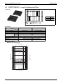
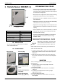
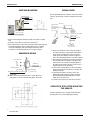
OHUS08-1FCU_b Option Handbook VRV Systems Indoor Fan Coil Units AMERICAS 1645 Wallace Drive, Suite 110 Carrollton, TX75006 [email protected] www.daikinac.com Jan. 2008 OHUS08-1FCU Printed in U.S.A. 02/08 K AK·FS AMERICAS OHUS08-1FCU_b OHUS08-1FCU_b Options Handbook Indoor Units 1. FXFQ - 3’x3’ Ceiling Mounted Cassette Type (Multi Flow) - .......................................3 1.1 BYC125K-W19 — Decoration Panel ................................................................... 3 1.2 KDBP55H160WA — Panel Spacer .......................................................................7 1.3 KDDP55D160(K) — Fresh Air Intake Kit ..............................................................9 1.4 KAFP552H80·160, KAFP553H80·160 — Replacement High Efficiency Filter ... 19 1.5 KAFP55D160 — Ultra Long Life Filter Kit (including filter chamber) .................. 20 1.6 KAFJ55K160H — Replacement UltraLong-Life Filter Unit ................................ 22 1.7 KDDFP55D160 — Filter Chamber ...................................................................... 23 1.8 KAFJ551K160 — Replacement Long Life Filter ................................................ 25 1.9 KDBHJ55K160 — Sealing Member of Air Discharge Kit ................................... 26 1.10 KK5J55160 — Chamber Connector Kit .......................................................... 28 2. FXZQ - 2’x2’ Ceiling Mounted Cassette Type (Multi Flow) - ..................................... 29 2.1 BYFQ60B8W1U — Decoration Panel ..................................................................29 2.2 KDBHQ44B60 — Sealing Member of Air Discharge Outlet ................................ 32 2.3 KDBQ44B60A — Panel Spacer ...........................................................................35 2.4 KAFQ441B60 — Replacement Long-Life Filter ...................................................38 2.5 KDDQ44X60 — Fresh Air Intake Kit (Direct Installation Type) ............................39 3. FXDQ - Slim Ceiling Mounted Duct Type - .................................................................41 3.1 KDT25N32·50·63 — Installation Kit for High Humidity .........................................41 4. FXSQ - Ceiling Mounted Built-In Type - .................................................................... 42 4.1 BYBS32·45·71·125DJW1 — Decoration panel ................................................... 42 4.2 KTBJ25K36·56·80·160W — Service Access Panel ............................................ 46 4.3 KAFJ252L36·56·80·160 / KAFJ253L36·56·80·160 — High-Efficiency Filter ....... 47 4.4 KAFJ251K36·56·80·160 — Replacement Long-Life Filter ...................................50 4.5 KAJ25L36·56·80·160D — Filter Chamber for Bottom Suction ............................ 51 4.6 KAJ25L36·56·80·160B — Filter Chamber for Rear Suction ................................ 52 4.7 KSA-25K36·56·80·160 — Canvas Duct (Air Suction Canvas) ............................ 55 4.8 KBBJ25K36·56·80·160 — Screening Door ......................................................... 56 4.9 KDJ2507K36·56·80·160 — Air Suction Flange (Rear Return) ........................... 57 4.10 KDAJ25K36·56·71·140 — Air Discharge Adaptor ............................................ 58 Indoor Units 1 OHUS08-1FCU_b 5. FXMQ - Ceiling Mounted Duct Type - ....................................................................... 59 5.1 KAFP372A80·160 / KAFP373A80·160 — High-Efficiency Filter ......................... 59 5.2 KDDFP37A80·160 — Filter Chamber ..................................................................63 5.3 KAFP371A80·160 — Long-Life Replacement Filter ............................................66 6. FXHQ - Ceiling Suspended Type - ............................................................................ 67 6.1 KAFJ501D56·112·160 — Replacement Long-Life Filter ..................................... 67 7. FXLQ / (FXNQ) - (Concealed) Floor Standing - ........................................................ 68 7.1 KAFJ361K45·71 — Long Life Replacement Filter .............................................. 68 8. Remote Sensor ...........................................................................................................69 2 Indoor Units OHUS08-1FCU_b FXFQ - 3’x 3’ Ceiling Mounted Cassette Type (Multi Flow) - 1.FXFQ - 3’x 3’ Ceiling Mounted Cassette Type (Multi Flow) 1.1 BYC125K-W19 — Decoration Panel Never place the panel facing down, leaning against a wall, or upon a projecting object. Never touch or put pressure on the louver or it may malfunction. . Indoor Units 3 FXFQ - 3’x 3’ Ceiling Mounted Cassette Type (Multi Flow) - OHUS08-1FCU_b Refer to the Installation Manual attached to the indoor unit for installation instructions. Set the decoration panel to the indoor unit body by matching the positionlouver of themotor louverofmotor of the decoration to theposition piping the decoration panel topanel the piping position of the indoor unit, as shown in Figure 4. Install the decoration panel: Temporarily install the decoration panel to the indoor unit by hanging the latch on the opposite side of the louver motor of louver motor of the the decoration panel to the hook of the indoor unit body. (2 positions) Temporarily hang the remaining 2 latches to the hooks on the sides of the indoor unit. Be careful not to let the louver motor lead louver motor lead wirewire get caught in the sealing material. Screw all 4 hex head screws (located directly beneath the latches) in approximately 3/16”. Panel will rise. Adjust the decoration panel by turning it to the arrowed direction in Fig. 4 so that the ceiling opening is completely covered. Tighten the screws unitl the thickness ofsealing the sealing material between the decoration andindoor the indoor unit body reduces material between the decoration panelpanel and the to 3/16-5/16 inches. Indoor Unit Sealing material Ceiling material 3/16 - 5/16 in. Decoration panel Air outlet Hook Latch Piping position Louver motor 4 Indoor Units OHUS08-1FCU_b FXFQ - 3’x 3’ Ceiling Mounted Cassette Type (Multi Flow) - Tighten screws properly to prevent problems shown in Figure 5. Condensation formation the louver Make sure that the louver motor lead wire is not caught between the indoor unit and the decoration panel. Indoor Units 5 FXFQ - 3’x 3’ Ceiling Mounted Cassette Type (Multi Flow) - OHUS08-1FCU_b 1. Installing the Suction Grille: Install by reversing the procedure shown in PREPARATION OF DECORATION PANEL. suction can be installed in any orientation TheThe suction grillegrille can be installed in any orientation needed. needed. Note: Be careful not to get the louver motor lead wire caught when installing the suction grille. 2. Installing the Service Cover: Attach the string of the service cover to the pin of the decoration panel as shown in Figure 8. Install the service cover over the decoration panel. Install the service cover by sliding 4 latches to fit into the holes on the decoration panel. 6 Indoor Units OHUS08-1FCU_b 1.2 FXFQ - 3’x 3’ Ceiling Mounted Cassette Type (Multi Flow) - KDBP55H160WA — Panel Spacer Dimensions Unit:in 37-13/32 35-19/32 35-19/32 37-13/32 1-11/16 4- φ 3/16 Hole BYCP125D-W1 BYC125K-W19 9 BYC125KJ-W1 BYCP125K-W1 Never place the panel face down, against the wall, or on a projecting object as it may cause dents and damages the louver motor. in Indoor Units BYCP125D-W1 BYC125K-W19 BYC125KJ-W1 BYCP125K-W1 in 5-23/32~5-29/32 BYCP125D-W1 BYC125K-W19 9 BYC125KJ-W1 4-1/8~11/32 4-29/32~5-1/8 BYCP125K-W1 3-11/32~3-17/32 7 FXFQ - 3’x 3’ Ceiling Mounted Cassette Type (Multi Flow) - OHUS08-1FCU_b The panel spacer is not firmly fixed to the decoration panel so never push it forcefully or lean the decoration panel too far. 1P136564E 8 Indoor Units OHUS08-1FCU_b KDDP55D160(K) — Fresh Air Intake Kit Dimensions Unit: in 36 19-1/3 Inspection hatch (larger than 18) (Note. 2) 28-1/2 Connecting chamber (left) 3-1/2 KDDP55D160 (without T-shape, without Fan) 33-1/2 1.3 FXFQ - 3’x 3’ Ceiling Mounted Cassette Type (Multi Flow) - Inspection hatch (larger than 18) (Note. 2) 28-1/2 Connecting chamber (right) 6-1/2 φ6 Indoor unit Decoration panel Suction chamber Caution 1. An inspection hatch is required when inserting this kit (required for maintenance of the kit). 2. Mount one or the other of the inspection hatch. 3. This should be assembled locally. This kit is designed for intake from both sides. If one side is blocked, requiring intake from only one side, use KDDJ55B160. 4. If the wireless receiver unit for the remote controller is mounted to the main unit, air should be taken in from the right side. Model KDDP55D160 Item Fresh air intake method Fresh air intake by air conditioning fan. φ6 Diameter of connection duct Accessories T pipe joint: 1, Flexible duct: 2, Plate bands: 4, Mounting screws (M4×12) : 4, Installation manual Mass (Lbs) 11.25 Component Model KDDP55D160 KDDP55D160K (with T-shape, without Fan) Suction chamber Connecting chamber · Tpipe KDDP55D160-1 KDDJ55B160-2 Dimensions Unit: in 36 Inspection hatch (larger than 17-3/4) (Note. 2) 28-1/2 33-1/2 35-1/4 Connecting chamber (left) Flexible duct (Accessories) Inspection hatch (larger than 17-3/4) (Note. 2) 28-1/2 Connecting chamber (right) T pipe joint Intake duct (K-FDS15) (Accessories) (Separately sold) Plate band (Accessories) 6-1/2 φ6 Indoor unit use KDDJ55B160. Decoration panel Suction chamber Caution 1. Maximum length of the duct is 13 feet. 2. An inspection hatch is required when inserting this kit. (Required for maintenance of the kit.) 3. Mount one or the other of the inspection hatch. 4. This should be assembled locally. This kit is designed for intake from both sides. If one side is blocked requiring intake from only one side, use KDDJ55B160. 5. This kit cannot be used when the receiver for the wireless remote control is attached as it blocks intake from one side. Model Item Fresh air intake method Fresh air intake by air conditioning fan. φ6 Diameter of connection duct Accessories T pipe joint: 1, Flexible duct: 2, Plate bands: 4, Mounting screws (M4×12) : 4, Installation manual Mass (Lbs) 16 Model KDDP55D160K Indoor Units KDDP55D160K Component Suction chamber Connecting chamber · Tpipe KDDP55D160-1 KDDJ55B160K2 9 FXFQ - 3’x 3’ Ceiling Mounted Cassette Type (Multi Flow) - OHUS08-1FCU_b Make sure to use the attached or specified components to install the products, or the product may fall or have air leaks. Perform a trial operation after installation to ensure there is no abnormality. Kit Name KDDP55D160 KDDP55D160K VRV This kit can be installed to the Ceiling Mounted Cassette Type Air Conditioner (Multi-flow). Before installation, make note of the indoor unit number. Refer to the installation manuals for instructions for the indoor unit and the decoration panel. Applicable indoor unit model FXFQ12·18·24·30·36MVJU SkyAir FCQ24-42MVJU 1. Refer to the following figure: When the intake from both sides cannot be obtained due to an obstacle, one side intake is acceptable. (In this case, make sure to close the opening with the closing material (5). - intake, the noise will be larger than intake from both sides. In case of one-side Example of one-side - intake: 2. Inspection hatch (larger than 18”)18'' 12-24 MBH 30-36 MBH 28-1/2 11-5/32 13-3/4 Install either one of the hatches When installing the wireless receiver kit on the indoor unit, the duct must be led from the right side, as shown. In this case, use KDDP55D160. 1. Remove the decoration panel (not required for new installation). Remove the decoration panel in the reverse step when the panel is installed. Refer to the Installation manual of the decoration panel for details. 2. Temporarily install the suction chamber to the indoor unit by hanging the latch on the opposite side of the suction chamber to the hook of the indoor unit body. (2 positions). Temporarily hang the remaining 2 hooks of the suction chamber to the hooks on the sides of the indoor unit. When the indoor unit is already installed, temporarily hang the hook to the suspension bracket and fix the hook. Installation set outline of the indoor unit: . 3. Tighten 2 hexagon screws located beneath the latches until the thickness of the sealing material of chamber reduces to 1/5 to 1/3”. (2 positions) (2 positions) (4 positions) 3K011144-1A 10 Indoor Units OHUS08-1FCU_b FXFQ - 3’x 3’ Ceiling Mounted Cassette Type (Multi Flow) - Note: 13 feet 1. The Fresh Air Intake components, (including the duct, T-Joint, Air Filter, and Hood), is field supplied. 2. When the fresh air duct is over 13 feet, a field-supplied duct fan is required. 3. When using the wireless remote controller, the flexible duct cannot be connected in the same right hand position. Note: 1. The Fresh Air Intake Kit, (including the duct, T-joint, Air Filter and hood), 13 feet is field supplied. 2. When the fresh air duct is over 13 feet, a field-supplied duct fan is required. 3. The wireless remote controller and field-supplied duct fan cannot be used simultaneously. Indoor Units 11 FXFQ - 3’x 3’ Ceiling Mounted Cassette Type (Multi Flow) - 1.4 OHUS08-1FCU_b KAFP556D80·160, KAFP557D80·160 — High Efficiency Filter Kit (including filter chamber) KAFP556D80 Dimensions Unit: in 2 (Dimensions when mounted) 33-1/4 33-1/4 Caution ·Field setting by remote controller is necessary when the high efficiency filter is installed. Model Item Air flow rate CFM Collecting Efficiency (%) KAFP556D80 KAFP556D160 KAFP557D80 KAFP557D160 671 1236 671 1236 65% (NBS Colorimetric method) Initial pressure loss (”Wg) Life (h) 0.39 or less Non-woven fabric of synthetic fiber Non-woven fabric of synthetic fiber 2,500 h (Dust Concentration 0.15 mg/m3) 1,800 h (Dust Concentration 0.15 mg/m3) Accessories Mass (Lbs) , Applicable Models Replacement filter (optional accessories) MERV-12 0.14 or less Final pressure loss (”Wg) Filter MERV-11 Installation manual 9.6 11.25 9.6 11.25 FXFQ12,18,24 MVJU FXFQ30,36MVJU FCQ24,30,36,42 MVJU FXFQ12,18,24 MVJU FXFQ30,36MVJU FCQ24,30,36,42 MVJU KAFP552H80 KAFP552H160 KAFP553H80 KAFP553H160 * For the applicable ASHRAE 52.2 MERV ratings, refer to the following 4 pages. 12 Indoor Units OHUS08-1FCU_b Indoor Units FXFQ - 3’x 3’ Ceiling Mounted Cassette Type (Multi Flow) - 13 FXFQ - 3’x 3’ Ceiling Mounted Cassette Type (Multi Flow) - 14 OHUS08-1FCU_b Indoor Units OHUS08-1FCU_b Indoor Units FXFQ - 3’x 3’ Ceiling Mounted Cassette Type (Multi Flow) - 15 FXFQ - 3’x 3’ Ceiling Mounted Cassette Type (Multi Flow) - 16 OHUS08-1FCU_b Indoor Units OHUS08-1FCU_b FXFQ - 3’x 3’ Ceiling Mounted Cassette Type (Multi Flow) - Applicable Indoor Units KAFP556D80 or KAFP557D80 KAFP556D160 or KAFP557D160 FXFQ12·18·24MVJU FXFQ30-36MVJU / FCQ24-42MVJU Applicable Indoor Units When you install the High Efficiency Filter, the setting by the remote controller is required. Set the remote controller at the field setting mode and change the setting position number as shown on the table. Refer to the operation manual of the remote controller for the proper field setting. Installation of the High Efficiency Filter unit 1. Remove the decoration panel (not required for new installation). Remove the decoration panel in the reverse step when the panel is installed. (Refer to the installation manual of the decoration panel for details. High Efficiency Filter 2. Remove the High Efficiency Filter. 3. Temporarily install the filter chamber to the indoor unit by hanging the latch on the opposite side of the filter chamber to the hook of the indoor unit body (2 positions). Temporarily hange the remaining two hooks of the filter chamber to the hooks on the sides of the indoor unit. When the indoor unit is already installed, hang the hook to the suspension bracket temporarily and fix the hook. *Installation set outline of the indoor unit: 4. Tighten 2 hexagon screws located beneath the latches until the thickness of the sealing material of chamber reduces to 1/5 to 1/3”. 1/5 to 1/3" (2 positions) (2 positions) (4 positions) 3K011145A Indoor Units 17 FXFQ - 3’x 3’ Ceiling Mounted Cassette Type (Multi Flow) - OHUS08-1FCU_b Installation of the indoor unit and the High Efficiency Filter unit Install the indoor unit and the High Efficiency Filter unit referring to the Installation Manual. Refer to the drawing on the right for the height of the unit. Complete full installation of refrigerant piping and drain piping. Attach the installation paper pattern with screws to protect the unit from dirt. (7-7/8) If you attach the filter after the unit is already installed, raise the height of the unit as show in the figure to the right. High Efficiency Filter unit Install the High Efficiency Filter after connections are made, as shown in fig 7. (4 positions) High Efficiency Filter Refer to the Installation Manual attached to the Wireless Remote Controller Kit (optional) for details. Put the connector for the receiver lead wire through the rubber bushing and connect to the indoor PC board. If the filter chamber and OA kit are used, an extended wire harness must be ordered (KK5J55160); see page 28. 3K011145A 18 Indoor Units OHUS08-1FCU_b KAFP552H80·160, KAFP553H80·160 — Replacement High Efficiency Filter 22-1/16 1.5 FXFQ - 3’x 3’ Ceiling Mounted Cassette Type (Multi Flow) - 0 13/32 · Cannot be water-washed for reuse. · The Filter Chamber (KDDFP55D160) is required when the high efficiency filter is installed. Model Item Average efficiency Number of sheets included Airflow rate CFM 21-1/4 -3/32 KAFP552H80 13/32 KAFP552H160 65 (colorimetric method) 1 1 1 1236 671 1236 1/32 1/3 Filter element Applicable Models Indoor Units MERV-12 1 Initial pressure loss (“Wg) Mass (Lbs) MERV-11 KAFP553H160 671 Final pressure loss (“Wg) Life (h) KAFP553H80 Non-woven fabric of synthetic fiber 2,500 (dust concentration 0.15 mg/m3) 1.3 2.6 1,800 (dust concentration 0.15 mg/m3) 1.3 2.6 FXFQ30,36MVJU FXFQ30,36MVJU FXFQ12,18,24MVJU FCQ24,30,36,42MVJU FXFQ12,18,24MVJU FCQ24,30,36,42MVJU 19 FXFQ - 3’x 3’ Ceiling Mounted Cassette Type (Multi Flow) - 1.6 OHUS08-1FCU_b KAFP55D160 — Ultra Long Life Filter Kit (including filter chamber) Dimensions Unit:in 2 (dimensions when attached) 12 33 33 Caution · In order to mount a ultra long life filter unit, setting of the main unit of indoor unit should be made. · Replacement filter (KAFJ55K160H) is available as an optional accessory. Mounting locations Filter cleaning period Locations with much dust Approximately every 5,000 hours Model Item Average efficiency (%) 50 (Gravity method) Initial pressure loss ("Wg) 0.10 or less Final pressure loss ("Wg) Filter element Life (h) Mass (Lbs) Component parts Locations with little dust Approximately every (e.g. offices) 5,000 hours KAFP55D160 0.31 or less Mildew Proof Resin Net 5,000 (dust concentration 0.3 mg/m3) 12-1/2 Ultra long-life filter unit Installation Manual (2 positions) 3/16 in ~ 5/16 in (2 positions) (2 positions) (4 positions) 3K011147 20 Indoor Units OHUS08-1FCU_b FXFQ - 3’x 3’ Ceiling Mounted Cassette Type (Multi Flow) - : (7-7/8 in) (7-7/8 in) : * * 3K011147 3K011147 Indoor Units 21 FXFQ - 3’x 3’ Ceiling Mounted Cassette Type (Multi Flow) - 1.7 OHUS08-1FCU_b KAFJ55K160H — Replacement UltraLong-Life Filter Unit Dimensions Unit:in 22 22 2-1/3 Can be water-washed. Can be reused. Model Item Average efficiency (%) Initial pressure loss ("Wg) Final pressure loss ("Wg) Life (h) Filter element Number of sheets included Mass (Lbs) 22 KAFJ55K160H 50 (Gravity method) 0.031 0.33 5,000 (dust concentration 0.3 mg/m3) Mildew-proof resin net 1 4.5 Indoor Units OHUS08-1FCU_b 1.8 FXFQ - 3’x 3’ Ceiling Mounted Cassette Type (Multi Flow) - KDDFP55D160 — Filter Chamber Dimensions Unit:in 33-7/32 33-7/32 1-31/32 (dimensions when attached) Model Item Optional filter High-efficiency filter 65 (colorimetric method) KAFP552H80 KAFP552H160 MERV rated KAFP553H80 Ultra long-life filter Mass (Lbs) KDDFP55D160 KAFP553H160 KAFJ55K160H 6.6 (2 positions) 3/16 in~5/16 in (2 positions) (2 positions) (4 positions) Indoor Units 23 FXFQ - 3’x 3’ Ceiling Mounted Cassette Type (Multi Flow) - OHUS08-1FCU_b (7-7/8 in) : * 3K011147 24 Indoor Units OHUS08-1FCU_b 1.9 FXFQ - 3’x 3’ Ceiling Mounted Cassette Type (Multi Flow) - KAFJ551K160 — Replacement Long Life Filter KAFJ551K160 Dimensions Unit:in 21-11/32 >PS< 1-3/32 22-1/16 · Has the same specifications as the standard equipment. · Can be water washed. Can be reused. Model Item Average efficiency (%) Initial pressure loss(”Wg) Final pressure loss(”Wg) Life (h) Filter element Number of sheets included Mass (Lbs) Indoor Units KAFJ551K160 65 (Gravity method) 0.03 or less 0.20 2,500 (dust concentration 0.15 mg/m3) Mildew-proof resin net 1 0.7 25 FXFQ - 3’x 3’ Ceiling Mounted Cassette Type (Multi Flow) - 1.10 OHUS08-1FCU_b KDBHJ55K160 — Sealing Member of Air Discharge Kit Caution zRefer to the installation manual for both indoor unit and the decoration panel. zWhen you install other optional kit, it may not be possible to select the 3-way or 2-way air discharge. For details, refer to the manual for the optional kit or the catalogue. zContents of Kit Prior to installation make sure you have the complete kit of parts. Name Sealing material(A) Sealing material(B) Sealing material(C) Sealing material(D) Quantity 1 piece 1 piece 1 piece 1 piece Shape and marking Name Quantity Shape and marking Insulation for top plate 1 piece 1 piece Insulation for side plate 1 piece 9-1/2 x 24-1/4” 2 pieces 9-1/2 x 21-1/4” 1 piece Moisture absorber for bell-mouth 2 pieces 1 piece Moisture absorber for horizontal vane 5 kinds 9-1/2 x 19-1/3” Make sure each symbol of sealing material corresponds to the air outlet. J : 1P012222-1B-1 26 Indoor Units OHUS08-1FCU_b FXFQ - 3’x 3’ Ceiling Mounted Cassette Type (Multi Flow) - It is required to make a local setting on the remote controller according to the installation of the indoor unit. The direction of air discharge should also be set by the remote controller. The 3 different kinds of settings, Mode number, Setting switch number, and Setting of the direction of air discharge, should also be set with the remote controller. Refer to Local setting on the Operation Manual of the remote controller for the setting procedure. 1. Set according to the table of The direction of air discharge and the installation of the sealing material. Check the setting position number corresponding to the direction of air discharge. 2. Refer to the local setting for the remote controller in the Operation Manual and change the setting according to the position determined by (1) as shown in the table below. FXFQ12,24MVJU 3 FXFQ30,36MVJU FCQ24,42MVJU Installation of the insulation (1) Installation to the side plate Adhere insulation for side plate to the side of indoor unit. 30M·36M 12~24M Put the wire through the slit of the insulation. (2) Installation to the top plate Adhere insulation for top plate When adhering insulation, align its edge with the bottom line of casing. When adhering insulation, align its edge with the bottom line of casing. , to the top of the indoor unit. (3) Adhere the moisture absorber for horizontal vane to the edge of the horizontal vane of air outlet (Fig. 2). (Choose the same color as panel.) Horizontal vane Moisture absorber for horizontal vane Fig. 2 Align it with the upper edge of horizontal vane. Fig. 1 Horizontal vane Moisture absorber for horizontal vane (4) Adhere the moisture absorber in accordance with the reference surface without wrinkles. (Fig. 4) Adhere the moisture absorber in accordance with the reference line . (Fig. 5) Reference surface (Fig. 3) Swing connector Swing motor Sticking reference Adhere it from the edge of switch box. Switch box Bellmouth Sticking reference Fig. 5 Fig. 4 JC : 1P012222-1B-2 Indoor Units 27 FXFQ - 3’x 3’ Ceiling Mounted Cassette Type (Multi Flow) - 1.11 28 OHUS08-1FCU_b KK5J55160 — Chamber Connector Kit Indoor Units OHUS08-1FCU_b FXZQ - 2’x 2’ Ceiling Mounted Cassette Type (Multi Flow) - 2. FXZQ - 2’x 2’ Ceiling Mounted Cassette Type (Multi Flow) 2.1 BYFQ60B8W1U — Decoration Panel 1. BEFORE INSTALLATION 1. PRECAUTIONS • Refer also to the installation manual attached to the indoor unit. 2. ACCESSORIES Installation manual. Screw (4 pcs.) 3. NOTE TO INSTALLER Be sure to instruct the customer how to properly operate the system showing them the operation manual attached to the indoor unit or the outdoor unit. 2. PREPARATION OF DECORATION PANEL For this unit, you are able to select air flow directions. To discharge air in 2 or 3 directions, it is necessary to purchase optional kit, Sealing Member of Air Discharge Outlet. HANDLING OF DECORATION PANELS • Never place the panel facing down nor lean it against a wall nor leave it on a projecting object. • To prevent malfunction, never touch or put pressure on the louver. (1) Remove the suction grille from the decoration panel. 1 Open the suction grille by sliding the 2 suction grille tabs in the direction of the arrow. (Refer to Fig. 1) Fig. 1 2 Detach the suction grille from the decoration panel by lifting the grille up approximately 45 degrees. (Refer to Fig. 45° Fig. 2 Indoor Units 29 FXZQ - 2’x 2’ Ceiling Mounted Cassette Type (Multi Flow) - 3. OHUS08-1FCU_b INSTALLATION OF THE DECORATION PANEL TO THE INDOOR UNIT BODY Refer to the installation manual attached to the indoor unit for the installation of the indoor unit. (1) Match the “PIPING SIDE” and “DRAIN SIDE” displays on the decoration panel with the position of the piping section and drain section on the indoor unit. (2) Install the decoration panel. 1. Make sure the wire has not come out of the groove for the wiring route inside the indoor unit. (3 locations) If it has, put it back in. (Connecting the panel with wires out of the groove may cause water leakage.) 2. Temporarily tighten the attached screws approximately 1/5” (5mm) into the opposing sides of the control box in the indoor unit. (Refer to Fig. 3) Attached screws Wiring route grooves (2 locations) (3 locations) Fig. 3 Control box 3. Slide the panel in the direction of the arrow, passing the 2 attachment holes (the “ temporarily tight ened screws. (Refer to Fig. 4) ” shapes parts) over the Panel temporary suspension Fig. 4 4. Hang the panel temporary suspension on the hook located on the control box of indoor unit. (Refer to Fig. 5) Control box Hook Fig. 5 5. Attach the remaining 2 screws, and tighten all 4 screws until the sealant between the decoration panel and indoor unit is compressed to between 1/4-1/3” (6-8 mm) thick. (Refer to Fig. 6) Indoor unit 1/4-1/3”(6 - 8 mm) Ceiling material Sealant Decoration panel Section of air outlet Fig. 6 Horizontal blade 3PA64319-12N-2 30 Indoor Units OHUS08-1FCU_b FXZQ - 2’x 2’ Ceiling Mounted Cassette Type (Multi Flow) - [ PRECAUTIONS ] Air leak Improper tightening of screws can cause problems such as shown in Figure 7. Be sure to tighten correctly. Air leak from ceiling Contamination If a gap remains between the ceiling and the decoration panel after tightening the screws, readjust the indoor unit’s body height. Dew formation, dew dripping Fig. 7 (3) Wiring of the decoration panel (Refer to Fig. 8) 6. Remove the control box lid after making sure the power to the unit is off. 7. Connect the connectors for the louver motor lead wire installed on the decoration panel. Be sure to connect the connectors. Failure to do so prevents the louver from operating. 8. Replace the control box lid reversing the procedure to remove it. Make sure that the louver motor lead wire is not caught between the indoor unit and the decoration panel. Control box lid Pass the louver motor lead wire through the clamp material as shown in the diagram. After connection, store the connector inside the control box. Screws (2 locations) Hang the louver motor lead wire on this tab. Clamping material Louver motor lead wire Indoor unit side Louver motor lead wire Decoration panel side Fig. 8 4. INSTALLATION OF THE SUCTION GRILL Install by reversing the procedure shown in PREPARATION OF DECORATION PANEL. It is possible to install the suction grille in 4 directions by turning the suction grille. Change the direction when adjusting the direction of the suction grille of multiple units or in meeting customer demands. NOTE Be careful not to let the louver motor lead wire get caught when installing the suction grille. 3PA64319-12N-3 Indoor Units 31 FXZQ - 2’x 2’ Ceiling Mounted Cassette Type (Multi Flow) - 2.2 OHUS08-1FCU_b KDBHQ44B60 — Sealing Member of Air Discharge Outlet Component 4” x 7” 1” x 14-1/5” 4” x 14-1/2” 4” x 60-1/2” 2” x 4/5” 1/3” x 17-3/4” 1/3”(10mm) 1/3”(10mm) 1P109292B 32 Indoor Units OHUS08-1FCU_b FXZQ - 2’x 2’ Ceiling Mounted Cassette Type (Multi Flow) - The 3 different kinds of settings such as Mode Number, Setting Switch Number, and Setting Position Number must be made by the remote controller. For setting procedure, refer to Field Setting in the Operation Manual of the remote controller. Setting is according to number of air discharge outlets. Check the setting position number corresponding to the direction of air discharge in the following table: For safety, be sure to turn off the power before installing the decoration panel, affixing the insulation, and connecting the swing connector. 1P109292B Indoor Units 33 FXZQ - 2’x 2’ Ceiling Mounted Cassette Type (Multi Flow) - OHUS08-1FCU_b Louver connector Louver motor louver for louver louver louver Louver connector 34 Indoor Units OHUS08-1FCU_b 2.3 FXZQ - 2’x 2’ Ceiling Mounted Cassette Type (Multi Flow) - KDBQ44B60A — Panel Spacer Dimensions Installation 27-1/2 25-3/4 Unit:in 25-3/4 27-1/2 1-2/3 Ceiling surface Panel spacer 4- φ 5 Hole 1/6- · Using the panel spacer in areas of the ceiling with limited space makes it possible to install the air conditioner.. · Hides the gap between the decoration panel and the ceiling. Model Item Applicable decoration panel KDBQ44B60A BYFQ60BW1 Exterior White Material Outside frame: Resin Insulation: Foam polyethylene Component Parts Mass (lb) Applicable Models Panel spacer, Insulation, Sealant, Mounting screws, Installation manual 3.3 FXZQ07,09,12,18MVJU BYFQ60BW1 BYFQ60B8W1U Never place the panel face down, lean it against the wall, or place it on the protective object as doing so can dent or damange the surface of the panel or swing motor. Indoor Units 35 FXZQ - 2’x 2’ Ceiling Mounted Cassette Type (Multi Flow) - OHUS08-1FCU_b 10”(255mm) or more 5-1/2”(140mm) 9-2/3”(245mm) 7”(180mm) 11-1/5”(285mm) Adjust the height of the indoor unit, making sure that the piping does not come into contact with the ceiling joist. 1P107764C 36 Indoor Units OHUS08-1FCU_b FXZQ - 2’x 2’ Ceiling Mounted Cassette Type (Multi Flow) - Install the decoration panel to the indoor unit according to its installation manual. The panel spacer is not firmly fixed to the decoration panel, so never press directly on the panel spacer and do not lean on the decoration panel. 1P107764C Indoor Units 37 FXZQ - 2’x 2’ Ceiling Mounted Cassette Type (Multi Flow) - 2.4 OHUS08-1FCU_b KAFQ441B60 — Replacement Long-Life Filter Dimensions: inches 5/8 1/8 1/12 12-2/5 5-1/10 14-1/3 12-2/5 8-1/2 1/3 1/6 1/10 13-1/10 1/2 1/5 1/6 2/3 9/10 1/3 1/3 1/6 1/6 12-1/2 1-1/10 x P10 = 11 1/6 x P50 = 7-9/10 13-2/5 2P100214B 38 Indoor Units OHUS08-1FCU_b 2.5 FXZQ - 2’x 2’ Ceiling Mounted Cassette Type (Multi Flow) - KDDQ44X60 — Fresh Air Intake Kit (Direct Installation Type) 1. This kit can be installed to the Ceiling-mounted Cassette type (Multi-flow). 2. When installing this kit, duct (nominal diameter of 4” (100 mm) is required on site. In case the metal duct is penetrated through the wooden walls, make sure the duct and the wall are electically insulated. Install the duct inclined downward toward outdoors so that rain cannot enter the duct. Use an inclination of 1/100 to 1/50. To avoid birds, small animals, or insects getting inside the duct, make sure to install netting where it contacts outside air. Contents of kit: Prior to installation, make sure you have the complete kit of parts. Necessary tools: Philips head screwdriver, needle-nose pliers, cutter Cut it off with needle-nose pliers 2P108307A Indoor Units 39 FXZQ - 2’x 2’ Ceiling Mounted Cassette Type (Multi Flow) - Apply proper insulation for the hole of the insulation OHUS08-1FCU_b and hole of the indoor unit. 2P108307A 40 Indoor Units OHUS08-1FCU_b FXDQ - Slim Ceiling Mounted Duct Type - 3. FXDQ - Slim Ceiling Mounted Duct Type 3.1 KDT25N32·50·63 — Installation Kit for High Humidity Kit in 24-7/16 32-5/16 40-3/16 7-7/8 in 27-23/32 35-19/32 43-15/32 in 15-11/32 in 9-7/16 in in 3-17/32 3-17/32 14-31/32 8-5/32 in 27-9/16 35-7/16 43-5/16 FXDQ24MVJU 8-5/32 in 27-9/16 35-7/16 43-5/16 16-17/32 15-11/32 Indoor Units FXDQ18MVJU FXDQ07,09,12MVJU Applicable Model 41 FXSQ - Ceiling Mounted Built-In Type - OHUS08-1FCU_b 4. FXSQ - Ceiling Mounted Built-In Type 4.1 BYBS32·45·71·125DJW1 — Decoration panel Panel Unit BYBS32 DJW1 BYBS45 DJW1 BYBS71 DJW1 BYBS125 DJW1 Model FXSQ 09/12MVJU FXSQ 18MVJU FXSQ 24MVJU FXSQ 30/36/48MVJU Slide the lever, then pull up and unhook the inner frame assembly. . 42 Indoor Units OHUS08-1FCU_b FXSQ - Ceiling Mounted Built-In Type - Air discharge adapter (optional) (optional) Indoor Units 43 FXSQ - Ceiling Mounted Built-In Type - OHUS08-1FCU_b Install the remaining two screws to the suction panel canvas and tighten all four screws securely until the sealing material becomes 13/32” to 19/32” thick. Install the suction panel and decoration panel to the indoor unit body in the correct direction with the nameplate on the panel coming to the position as shown in the following figure: 44 Indoor Units OHUS08-1FCU_b FXSQ - Ceiling Mounted Built-In Type - Ensure that the ceiling tile material does not exceed 2/3” thickness. Indoor Units 45 FXSQ - Ceiling Mounted Built-In Type - 4.2 OHUS08-1FCU_b KTBJ25K36·56·80·160W — Service Access Panel KTBJ25K36W Unit:in 27-15/32 Dimensions 1-9/16 4-1/4 Model A Ceiling opening KTBJ25K36W 24-21/32 23-27/32 × 26-25/32 KTBJ25K56W 30-9/16 29-3/4 × 26-25/32 KTBJ25K80W 42-3/8 41-9/16 × 26-25/32 KTBJ25K160W 58-1/8 57-5/16 × 26-25/32 • The inspection hatch can be made to look nice with the service access panel. • Thin 1/3” design for the exposed part. Model Item Main applicable models KTBJ25K36W KTBJ25K56W KTBJ25K80W KTBJ25K160W FXSQ12MVJU FXSQ18MVJU FXSQ24MVJU FXSQ30·36·48 MVJU Color White Accessories Installation manual Weight (Lbs) 13.2 14.3 20 24 Caution • Ceiling joist and ceiling joist support required. (Locally procured.) BEFORE INSTALLATION: 1. Make an opening in the ceiling. 3. Install the inner frame assembly on the outer frame assembly. Outer frame assembly Inner frame assembly 2. Install ceiling joist supports to fit the ceiling opening. Ceiling joist support Ceiling joist Ceiling opening Ceiling Model A KTBJ25K36 23-7/8” KTBJ25K56 29-3/4” KTBJ25K80 41-1/2” KTBJ25K160 57-1/3” 57-5/16 The ceiling board can be installed into the inner frame assembly as follows: 1. Remove decoration panel retainer from the inner frame assembly. 2. Remove the decoration panel and substitute with the ceiling board. 3. Set the ceiling board by the retainer removed in step 1 above. CAUTION: When the ceiling board is installed, the decoration panel is not needed. INSTALLATION: 1. Remove inner frame assembly which can be removed by turning the retainer 90º with a screwdriver. Inner frame assembly Decorative panel retainer Ceiling board Decorative panel Outer frame assembly Inner frame assembly 2. Install outer frame assembly on the ceiling by hooking the hanging lug on the ceiling joist support, and then tightening the wing nut to fix the frame assembly. Wing nut Hanging lug Ceiling 46 Indoor Units OHUS08-1FCU_b KAFJ252L36·56·80·160 / KAFJ253L36·56·80·160 — High-Efficiency Filter (Excluding Filter Chamber) Dimensions Unit:in Model KAFJ252L36 KAFJ253L36 KAFJ252L56 KAFJ253L56 A 19-11/16 25-19/32 17-5/8 × 1 KAFJ252L80 KAFJ253L80 19-3/4 × 1 KAFJ252L160 KAFJ253L160 27-15/32 × 1 25-21/32 × 1 14-3/16” 14-3/16 KAFJ252L56 31/32 31/32” 4.3 FXSQ - Ceiling Mounted Built-In Type - • Cannot be water washed for reuse. • Bottom return: The Filter Chamber (for High efficiency filter) (KAJ25L36D · 56D · 80D · 160D) is required when the high efficiency filter is installed. • Rear return: The Filter Chamber (for high-efficiency filter) (KAJ25L36B · 56B · 80B · 160B) is required when the high-efficiency filter is installed. 65 (colorimetric method) Model Item KAFJ252L36 KAFJ252L56 318 494 Airflow rate CFM Average efficiency (%) KAFJ252L160 671 1342 65 (colorimetric method) Initial pressure loss (”Wg) 0.05 or less 0.56 or less Final pressure loss (”Wg) 0.56 or less 0.09 or less 0.39 2,500 (dust concentration 0.15 mg/m3) Life (h) Filter element Flame-resistant type (with mildew-proof) Number of sheets included 1 Mass (Lbs) Applicable Indoor Units Model Item 1 1.1 2 (each 1) 1.3 2 (each 1) 2 3 FXSQ30,36,48 MVJU FXSQ12MVJU FXSQ18MVJU FXSQ24MVJU KAFJ253L36 KAFJ253L56 KAFJ253L80 KAFJ253L160 318 494 671 1342 Airflow rate CFM MERV-13 Efficiency MERV-13 KAFJ252L80 Initial pressure loss (“Wg) 0.09 or less 0.11 or less Final pressure loss (“Wg) 0.11 or less 0.15 or less 0.45 1,800 (dust concentration 0.15 mg/m3) Life (h) Filter element Flame-resistant type (mildew proof) Number of sheets included Mass (Lbs) Applicable Indoor Units 1 1 2 (each 1) 1.1 1.3 2 FXSQ12MVJU FXSQ18MVJU 2 (each 1) 3 FXSQ24MVJU FXSQ30,36,48 MVJU Note) • The filter chamber is required when the high efficiency filter is installed. Installation 1. Cassette fan mounted / High-efficiency filter Filter chamber for bottom suction 2. Ceiling return / High efficiency filter 3. Duct fan mounted / high efficiency filter Filter chamber for bottom suction Filter chamber for rear suction High-efficiency filter High-efficiency filter chamber Suction canvas Suction panel High-efficiency filter chamber High-efficiency filter Service access Screen plate for rear suction Service access High-efficiency filter * For applicable ASHRAE 52.2 MERV ratings, refer to the following 2 pages. Indoor Units 47 FXSQ - Ceiling Mounted Built-In Type - 48 OHUS08-1FCU_b Indoor Units OHUS08-1FCU_b Indoor Units FXSQ - Ceiling Mounted Built-In Type - 49 FXSQ - Ceiling Mounted Built-In Type - 4.4 OHUS08-1FCU_b KAFJ251K36·56·80·160 — Replacement Long-Life Filter Dimensions Unit:in 25/32 KAFJ251K36 A B Model A~B KAFJ251K36 19-29/32 × 14-27/32 KAFJ251K56 25-13/16 × 14-27/32 19-29/32 × 14-27/32 KAFJ251K80 17-3/4 × 14-27/32 KAFJ251K160 27-19/32 × 14-27/32 25-13/16 × 14-27/32 Specifications Model Item KAFJ251K36 KAFJ251K56 Average Efficiency (%) Pressure Loss (“Wg) KAFJ251K80 KAFJ251K160 50% (Gravity method) Initial 0.019 or less Final 0.20 Materials Mildew Proof Resin Net Number Required per Model 1 Life Time (h) 1 2 2 2,500 hours (dust particle concentration at 0.15 mg/m³) Applicable Model FXSQ12MVJU FXSQ18MVJU FXSQ24MVJU FXSQ30·36·48MVJU Note: The filter models for FXSQ12·18MVJU can be used also as Rear-suction types. Characteristics of filter 3 Air volume (ft /min) 212 247 282 318 353 530 706 1059 1413 1766 0.04 0.03 0.34 0.03 0.01 0.01 Pressure loss 0.02 0.02 (”Wg) 0.008 0.004 50 Indoor Units OHUS08-1FCU_b 4.5 FXSQ - Ceiling Mounted Built-In Type - KAJ25L36·56·80·160D — Filter Chamber for Bottom Suction Dimensions Unit:in 1-21/32 KAJ25L56D 15-9/32 16-5/32 unit:(in) • Filter replacement is easily performed. Model A 21-21/32 KAJ25L56D 27-9/16 KAJ25L80D 39-3/8 KAJ25L160D 55-1/8 KAJ25L36D KAJ25L56D KAJ25L80D KAJ25L160D 65 (colorimetric method) KAFJ252L36 KAFJ252L56 KAFJ252L80 KAFJ252L160 MERV-13 KAFJ253L36 KAFJ253L56 KAFJ253L80 KAFJ253L160 5 6.1 8 9 Item Inserted filter Model KAJ25L36D Mass (Lbs) Component parts Applicable Models Filter chamber, Panel attachment plate, Screws, Installation manual FXSQ12MVJU FXSQ18MVJU FXSQ24MVJU FXSQ30,36,48 MVJU Installation Indoor Units 51 FXSQ - Ceiling Mounted Built-In Type - 4.6 OHUS08-1FCU_b KAJ25L36·56·80·160B — Filter Chamber for Rear Suction Dimensions Unit:in 15-7/16 KAJ25L56B • May be used with either the long-life filter or the high-efficiency filter. • The suction duct can also be connected. Model Item Inner dimensions of flange (in) Inserted filter Width A 21-21/32 KAJ25L56B 27-9/16 KAJ25L80B 39-3/8 KAJ25L160B 55-1/8 KAJ25L36B KAJ25L56B KAJ25L80B KAJ25L160B 18-1/2 24-13/32 36-7/32 51 Length 9-27/32 65 (colorimetric method) KAFJ252L36 KAFJ252L56 KAFJ252L80 KAFJ252L160 MERV-13 KAFJ253L36 KAFJ253L56 KAFJ253L80 KAFJ253L160 18 22 31 35.2 Mass (Lbs) Component parts Applicable Models 52 Model KAJ25L36B Filter chamber, Screen plate for rear suction, Washer for suspension bracket, Screws, Installation manual FXSQ12MVJU FXSQ18MVJU FXSQ24MVJU FXSQ30,36,48 MVJU Indoor Units OHUS08-1FCU_b FXSQ - Ceiling Mounted Built-In Type - - (3) Install the long-life filter to the rail closest to the air intake. - - Indoor Units 53 FXSQ - Ceiling Mounted Built-In Type - OHUS08-1FCU_b Procedure When maintenance of filter is carried out from the side: (Refer to table for type of long-life filter.) - - - MERV-13 Procedure When maintenance of filter is carried out from the bottom: (3)Install the high-efficiency filter to the rail closest to the air intake. - - - (2) Install the high-efficiency filter to the rail closest to the air intake. - 54 Indoor Units OHUS08-1FCU_b 4.7 FXSQ - Ceiling Mounted Built-In Type - KSA-25K36·56·80·160 — Canvas Duct (Air Suction Canvas) Installation Dimensions Unit:in Model A B C D KSA-25K36 21-21/32 20-1/4 4-29/32 8-27/32 KSA-25K56 27-9/16 26-5/32 7-7/8 11-13/16 KSA-25K80 39-3/8 37-15/16 13-25/32 17-23/32 55-1/8 53-11/16 21-21/32 25-19/32 KSA-25K160 15-15/16 15-9/32 14-17/32 4-M5 tap 15-9/32 D 2-15/16-10-1/32 C C C B A D Victor chain D KSA-25K80 Sealant Panel side Main unit side • Can be attached so that there is no gap in the ceiling using the included turn buckle. Model Item KSA-25K36 KSA-25K56 4 5 Canvas duct Mass (Lbs) Component parts Indoor Units KSA-25K80 KSA-25K160 Flame retardant 6.1 8 Air suction canvas, Turn buckle · Mounting screw, Adjustment plate, Installation manual Applicable model BYBS32DJW1 BYBS45DJW1 BYBS71DJW1 BYBS125DJW1 Applicable indoor model FXSQ12MVJU FXSQ18MVJU FXSQ24MVJU FXSQ30,36,48 MVJU 55 FXSQ - Ceiling Mounted Built-In Type - 4.8 OHUS08-1FCU_b KBBJ25K36·56·80·160 — Screening Door Dimensions KBBJ25K36 Unit:in Approx. 3/16 Model A KBBJ25K36 21-1/16 KBBJ25K56 26-31/32 KBBJ25K80 38-25/32 15-29/32 9/16 13/32 KBBJ25K160 54-17/32 • Screens the bottom intake vent. Model Item KBBJ25K36 Appearance Mass (Lbs) Component par ts Applicable model KBBJ25K56 KBBJ25K80 KBBJ25K160 Galvanized steel plate 4 5 7 10 Blind board/Screening door, Screws, Installation manual FXSQ12MVJU FXSQ18MVJU FXSQ24MVJU FXSQ30·36·48MVJU Installation Filter chamber for rear suction Long-life filter Service access 56 Blind board/Screening door Indoor Units OHUS08-1FCU_b 4.9 FXSQ - Ceiling Mounted Built-In Type - KDJ2507K36·56·80·160 — Air Suction Flange (Rear Return) Dimensions Unit:in A 20-3/4 KDJ2507K56 26-21/32 KDJ2507K80 38-15/32 KDJ2507K160 54-7/32 10-15/16 31/32 Model KDJ2507K36 Model Item Size of connecting duct (in) Width KDJ2507K36 KDJ2507K56 18-25/32 24-11/16 Length KDJ2507K80 36-1/2 KDJ2507K160 52-1/4 8-31/32 Materials Galvanized steel plate Component parts Applicable model Flange for suction, Packing, Screws, Installation Manual FXSQ12MVJU FXSQ18MVJU FXSQ24MVJU FXSQ30·36·48MVJU Note : When converting an FXSQ indoor unit to rear return, the optional Screening Door is required. Example of installation (optional) Indoor Units 57 FXSQ - Ceiling Mounted Built-In Type - KDAJ25K36·56·71·140 — Air Discharge Adaptor KDAJ25K71 Model Item Duct connection diameter Installation KDAJ25K56 φ7-7/8×1 port Material • When the air-discharge adaptor is installed, “flexible duct” is required. • Pre-insulated to save time on site. KDAJ25K36 φ7-7/8×2 port Steel plate Mass (Lbs) KDAJ25K140 KDAJ25K71 φ7-7/8×4 port Resin 2.4 2.2 4 5 Air discharge adaptor, Screws (except KDAJ25K 36), Installation manual Component parts Applicable Models FXSQ12MVJU FXSQ18MVJU FXSQ24MVJU FXSQ30,36,48MVJU Dimensions Unit:in KDAJ25K56 4-9/16 KDAJ25K36 13-31/32 2 × 5-29/32=11-13/16 6-f9/32 holes 4-f11/32 holes 1-31/32 4.10 OHUS08-1FCU_b f7-7 /8 5-7/32 4-f9/32-f9/16 5/8 2-9/16 1/8 6-1/2 f7-7/8 f7-7/8 5-29/32 9-21/32 10-5/8 5-29/32 9-21/32 4-f9/32-f9/16 4-f9/32 10-5/8 47-7/16 31-11/16 4-f9/32-f9/16 10-1/4 19-3/32 KDAJ25K140 4-17/32 6-1/2 KDAJ25K71 4-f9/32 4-17/32 1-1/16 13-1/8 f7-7/8 10-5/8 9-21/32 5-29/32 10-5/8 5-29/32 9-11/32 10-1/4 19-7/8 8-f9/32 3 × 11-13/32=34-1/4 46-21/32 14-31/32 30-29/32 Set the screws in two locations of the indoor unit and fasten them temporarily. Leave 25/32”. Temporarily hook the adaptor for discharge on the screws, and then fasten all the screws. Fasten the screws tightly leaving no gap between the indoor unit and the discharge adaptor. 58 Indoor Units OHUS08-1FCU_b FXMQ - Ceiling Mounted Duct Type - 5. FXMQ - Ceiling Mounted Duct Type KAFP372A80·160 / KAFP373A80·160 — High-Efficiency Filter Dimensions Unit:in 1-23/32 KAFP372A80 1-23/32 5.1 Tape A Tape (White) A 12 12-0/2 (Black) Filter element Model KAFP372A80 KAFP373A80 KAFP372A160 KAFP373A160 Filter frame Filter element Filter frame A 13-31/32 13-31/32 21-21/32 21-21/32 Filter connected chart Specification Model 65% type 90% type Items KAFP372A80 KAFP372A160 KAFP373A80 KAFP373A160 Filter Chamber KDDFP37A80 KDDFP37A160 KDDFP37A80 KDDFP37A160 13-31/32×12×1-23/32 21-21/32×12×1-23/32 13-31/32×12×1-23/32 21-21/32×12×1-23/32 Dimension (W×D×T) (in) Average Dust Collection Efficiency (%) Initial Pressure Loss (“Wg) Colorimetric method 65% 0.14 Final Pressure Loss (“Wg) Filter Life Time (h) Seats Structured Applicable Models 0.10 MERV-12 0.15 0.22 0.39 0.14 0.22 0.39 Non-woven fabric of synthetic fiber Non-woven fabric of synthetic fiber 2500 hours (dust density 0.15mg/m³) 1800 hours (dust density 0.15mg/m³) 2 FXMQ30MVJU 2 FXMQ36 MVJU 2 FXMQ48 MVJU FXMQ30MVJU 2 FXMQ36 MVJU FXMQ48 MVJU Note: The filter chamber is separately required when the high efficiency filter is installed. * For applicable ASHRAE 52.2 MERV ratings, refer to the following 2 pages. Indoor Units 59 FXMQ - Ceiling Mounted Duct Type - 60 OHUS08-1FCU_b Indoor Units OHUS08-1FCU_b Indoor Units FXMQ - Ceiling Mounted Duct Type - 61 FXMQ - Ceiling Mounted Duct Type - OHUS08-1FCU_b Characteristics of filter KAFP372A80, KAFP372A160, KAFP373A80, KAFP373A160 Air volume (ft3/min) 177 353 706 1059 1413 1766 3531 0.40 KAFP373A160 KAFP373A80 KAFP372A160 KAFP372A80 0.04 Pressure loss Pressure loss 0.20 (”Wg) (Pa) 0.02 0.004 Air volume (m3/min) Installation (optional) - - - Installation Meet the airflow direction and arrow mark putting on the High-efficiency filter. The filter is optional and can be added later to the unit. 62 Indoor Units OHUS08-1FCU_b 5.2 FXMQ - Ceiling Mounted Duct Type - KDDFP37A80·160 — Filter Chamber KDDFP37A80 Dimensions Unit:in 5-25/32 Duct side Service space (Service cover side) 5/8 Unit side A Long-life filter B G (Connection duct opening) Sealing pad 1-3/16 4-23/32 5-21/32 (without sealing pad) 8-21/32 (without sealing pad) Unit side Model 4-5/16 3-1/8 1-15/16 3-13/16 12-9/16 1/32 15/32 High-efficiency filter 12-3/8 (Connection duct opening) hole D C Duct side Service cover E F G H KDDFP37A80 28-7/32 23-13/16 23-1/32 P5-29/32×3=17-23/32 3-7/32 17-23/32 22-7/16 9/16 KDDFP37A160 43-19/32 39-1/8 38-3/8 P5-29/32×5=29-17/32 Model 29-17/32 39-9/16 23/32 KDDFP37A80 KDDFP37A160 65 (colorimetric method) KAFP372A80 KAFP372A160 MERV-12 KAFP373A80 KAFP373A160 Long-life filter KAFP371A80 KAFP371A160 11 15.4 Item Inserted filter 5 Mass (Lbs) Accessories Applicable Models Mounting screws, Installation manual FXMQ30MVJU FXMQ36,48MVJU • Set the anchor bolts (the size of the anchor bolts should be M10.) Characteristics of filter KDDFP37A80, KDDFP37A160 Air volume (ft3/min) 177 353 706 1059 1413 1766 3531 0.40 KAFP373A160 KAFP373A80 KAFP372A160 KAFP372A80 0.04 Pressure loss Pressure loss 0.20 (”Wg) (Pa) 0.02 0.004 Air volume (m3/min) Indoor Units 63 FXMQ - Ceiling Mounted Duct Type - OHUS08-1FCU_b Installations Before Installation <The accessories necessary for installation work should not be cast away until the work has been finished.> (1) Determine a carry-in route. (2) Carry the filter chamber to the installation site in its original packaging. If it is already unpacked, use appropriate caution. Selection of the location to be installed <Refer to the installation manual attached to the indoor unit.> (1) Select an installation location that the customer agrees upon, and that conforms to the following conditions: 27-5/32 29-1/8 • Sufficient strength to bear the weight of the indoor unit and filter chamber. • Lower surface of a ceiling is not significantly inclined. • Service space can be kept from the viewpoint of installation. (2) There are four directions for removing the maintenance service cover of the filter. Direction of the removal should be changed in accordance with an installed condition. (At shipping, the cover is fitted at the opening and closing location A .) At this time, confirm the vertical direction of the filter chamber, by means of the top joint holes at the right and left sides of the connection side toward an air conditioner body. Air conditioner body Inspection hole ( 17-23/32 or more) Downside Refer to [item Preparation before installation -(1)] for how to change the direction for removing the cover. Air conditioner body NOTE: Be sure there is an inspection hole on the new maintenance side when you change the maintenance direction of the filter. Preparation before installation Chamber body 15-11/32 Blowoff Suction 13/32 or more Service space 14-9/16 B or more Top joint hole High-efficiency filter Long-life filter 5-29/32~11-13/16 A or more Take-out of the filter Upside Filter chamber High-efficiency filter Long-life filter 8-21/32 Note) Be sure to provide the inspection hole at a position of the service cover as shown in the upper left Figure. If a position of the inspection hole is too far from the chamber body, it is hard to take out the filters. Service cover (Unit: in) Unit name A B C D E KDDFP37A80 29-17/32 17-23/32 26-3/8 28-11/32 28-11/32 KDDFP37A160 43-5/16 29-17/32 41-23/32 43-11/16 43-11/16 Take-out of the filter <Refer to the installation manual attached to the indoor unit.> (1) If direction of taking out the filter is changed, the work should be made in the following procedure. Example) In the case of changing the opening and closing direction of the service cover from A Selection of the location to be installed -(2)] to C as shown in [item 1. Detach the buckle for fixing the service cover. (Fig.1) 2. Rotate the service cover until it is detached from the pawl of the temporary latch. (Fig.2) 3. Detach the buckle, latch, and the screws of the side plate. Then, remove the cover from the chamber body. (Fig.3) 4. Relocate the parts detached in accordance with above item 3, to the new position. (Fig.4) 5. Fit the service cover in accordance with the reverse procedure of above item 2, and fix it with the buckle. Pawl Buckle for fixing the service cover NOTE: Make sure that the service cover is sercurely fixed with the buckle. If not fixed firmly, air leakage can occur. Side plate Buckle Temporary latch Buckle Temporary latch Service cover Fig.1 Temporary latch Side plate Fig.4 Fig.3 Fig.2 (2) Remove the suction inlet flange of the air conditioner body. (Fig.5) In the case of connecting the site-duct to the suction side of the filter chamber, fit the removed suction inlet flange to the suction side of the filter chamber, with the screws that have been detached from the air conditioner body. (3) When connecting ductwork to the air intake of the filter chamber, it is recommended that you use a flexible duct canvas (field supplied). This is to prevent indoor unit vibration from being transmitted to the ductwork and ceiling. (Fig. 6) Also, carry out lining work of the site-duct with an absorbent (heat insulation material), and fitting of rubber cushions on the hanger bolts for the air conditioner body. Air conditioner body Suction flange (to be removed) Hanger bolt M10 (ordered at site) Rubber cushion (ordered at site) Suction Discharge Connecting duct (field supplied) Canvas duct (field supplied) Air conditioner body Fig.5 Filter chamber Fig.6 Suction flange 3K016835 64 Indoor Units OHUS08-1FCU_b FXMQ - Ceiling Mounted Duct Type - Installation of the filter chamber If the filter chamber has been fitted into the air conditoner, you can lift up the products with hanger bolts. (1) Fit the mounting screws which are attached to this kit, onto the air conditioner body at two positions. (Fig.7) (2) Temporarily hang the air conditioner body with the screws fitted in accordance with above item (1), into the top joint holes of the filter chamber body, from inside. (3) After tightening the chamber at all outer screw holes using the attached mounting screws, tighten the two inside screws used for the temporary hanger. (Fig.8) (4) The air conditioner body and filter chamber should be installed horizontally by using a level vial, etc. <Remarks> • If screws are not tightened steadily, it may cause air leakage. • If the product is not installed horizontally, it may cause air leakage, or removal of the filter may become difficult. Air conditioner body Air conditioner body Temporary hang Top joint hole Filter chamber Fig.7 Mounting screw Fig.8 Fitting procedure of the filter In the case of High-efficiency filter Buckle for fixing the service cover Fitting procedure is same for both the 65% type and the 90% type. Preparation before (1) Remove the service cover. For the method of removal, refer to [item installation -(1)]. Detach the buckle for fixing the service cover and then rotate the service cover until it is detached from the pawl of the temporary latch. (2) Insert the first piece of filter (black Velcro strap attached;) while aligned into the wide filter rails, by setting the arrow mark to an airflow direction such that the filter label comes to upper face. (3) After confirming that the first filter has been inserted for more than its half size into the filter chamber, then insert the second piece of filter (white Velcro strap attached;) while fixing it to the first filter using a Velcro strap. (4) After inserting two filters securely into the back of the filter chamber, fit the service cover in accordance with the reverse procedure of item (1). High-efficiency filter Temporary latch Air flow Filter label Filter chamber Wide filter rail Black Velcro strap White Velcro strap NOTE: Make sure that the service cover is securely fixed with the buckle. If not fixed firmly, air leakage can occur. Service cover Long-life filter High-efficiency filter NOTE: Make sure that the service cover is securely fixed with the buckle. If not firmly fixed, air leakage can occur. Chamber body Insert for more than half size latching Buckle for fixing the service cover Suction side (1) Remove the service cover. For the method of removal, refer to [item Preparation before installation -(1)]. Detach the buckle for fixing the service cover and then rotate the service cover until it is detached from the pawl of the temporary latch. (2) Insert the first piece of filter while aligned into the narrow filter rails, by setting the arrow mark to an airflow direction such that the filter label comes to upper face. (3) After confirming that the first filter has been inserted for more than its half size into the filter chamber, then insert the second piece of filter while latching it on the pawl part of the first one. (Fig.9) The second filter cannot be fully inserted unless directions of the two filters fits. (4) After inserting the two filters securely into the back of the filter chamber, fit the service cover in accordance with the reverse. Air conditioner body side In the case of Long-life filter Filter chamber Position of each filter in the side view of the filter chamber (before the service cover is fitted) Temporary latch Air flow Pawl part Second piece of filter Filter label Pawl part NOTE: If the direction of each filter is different, proper latching with the same pawl cannot be made due to the stopper, and the filters cannot be inserted into the filter chamber. Pawl part First piece of filter Filter chamber Wide filter rail Pawl part Filter chamber Long-life filter Stopper Insert Service cover Pawl part Fig.9 3K016835 Indoor Units 65 FXMQ - Ceiling Mounted Duct Type - 5.3 OHUS08-1FCU_b KAFP371A80·160 — Long-Life Replacement Filter Dimensions Unit:in 12 11-25/32 KAFP371A80 A 13-29/32 21-9/16 25/32 31/32 23/32 31/32 Model KAFP371A80 KAFP371A160 Specifications Model KAFP371A80 Item Filter Chamber for Bottom Suction Dimensions (W×D×T) in KAFP371A160 KDDFP37A80 KDDFP37A160 14-1/8×12×31/32 21-25/32×12×31/32 Average Efficiency (%) Pressure Loss (“Wg) 50% (Gravity method) Initial 0.028 0.032 Final 0.20 (5mmH2O) Material Mildew-Proof Resin Net Number Required per Unit 2 Lifetime (h) 2 2,500 h (dust particle concentration at 0.15mg/m³) Applicable Model FXMQ30MVJU FXMQ36·48MVJU Characteristics of filter KAFP371A80, KAFP371A160 Air volume (ft3/min) 177 353 706 1059 1413 1766 3531 0.40 Pressure loss Pressure loss 0.20 0.04 (”Wg) (Pa) KAFP371A80 KAFP371A160 0.02 0.004 Air volume (m3/min) 66 Indoor Units OHUS08-1FCU_b FXHQ - Ceiling Suspended Type - 6. FXHQ - Ceiling Suspended Type 6.1 KAFJ501D56·112·160 — Replacement Long-Life Filter KAFJ501D56 Dimensions Unit:in A Model KAFJ501D56 KAFJ501D112 KAFJ501D160 25/32 10-1/32 10-1/4 A 16-15/16 16-15/16 19-13/32 7/16 • Can be water washed. Can be reused. Model Item KAFJ501D56 Average efficiency (%) 0.04 Final pressure loss (”Wg) 0.23 2,500 (dust concentration 0.15 mg/m3) Filter element Number of sheets included Mass (Lbs) Applicable Models KAFJ501D160 45 (Gravity method) Initial pressure loss (”Wg) Life (h) Indoor Units KAFJ501D112 Mildew-proof resin net 2 3 3 0.7 1.1 1.3 FXHQ12MVJU FXHQ24MVJU FXHQ36MVJU 67 FXLQ / (FXNQ) - (Concealed) Floor Standing - OHUS08-1FCU_b 7. FXLQ / (FXNQ) - (Concealed) Floor Standing 7.1 KAFJ361K45·71 — Long Life Replacement Filter • Can be water-washed. Can be reused. Model KAFJ361K71 KAFJ361K45 Item Applicable Models FXNQ,FXLQ18,24MVJU FXNQ,FXLQ12MVJU Average efficiency (%) 50 (Gravity method) Initial pressure loss (Pa) 9.8 or less Final pressure loss (Pa) 29.4 2,500 (dust concentration 0.15 mg/m3) Life (h) Filter element Mildew-proof resin net Number of sheets included 1 Mass (Lbs) 0.7 0.4 Dimensions KAFJ361K45 Unit:in KAFJ361K71 Filter element 7-13/32 19/32 UPPERSIDE UPPERSIDE 38-7/16 Filter frame Filter element 68 19/32 Filter frame 7-13/32 UPPERSIDE UPPERSIDE 27-13/32 Indoor Units OHUS08-1FCU_b Remote Sensor 8. Remote Sensor KRCS01-1A RECOMMENDATIONS FOR USE • Recommended for ceiling suspended (FXHQ) and ceiling concealed types (FXDQ, FXMQ, FXSQ, FXFQ, FXZQ) which often result in a difference between setpoint temperature and return air temperature. • Ducted style units in applications where outside air is being introduced or mixed at the unit’s return-air opening. 2-3/8” • Ducted style units that are applied in an open return-air plenum environment. • Applications where return air to the units is not substantially sourced from the area the unit is serving. 3/4” 1-31/32” ITEM Length of branch wiring Appearance MODEL KRCS01-1A 39’ 3/8” Light ivory (with Daikin logo) Housing Material ABS resin Package weight 15.5 oz Sensor box weight 1.1 oz Sensor box dimensions HWD 2-3/8” x 1-31/32” x 3/4” KIT APPLICATION This kit can be used for all indoor units in the SkyAir series, and the VRV series. KIT COMPONENTS Remote Sensor Accessory Bag • Applications where high ceilings result in temperature stratification between the occupied zone and the unit’s return-air opening. • Where simplified remote controllers (BRC2A71) are utilized and return air to the unit is not sourced entirely form the area that the unit is serving. • The sensor for detecting the temperature can be placed away from the indoor air conditioner. Branch wiring is included in the kit. REMOVING THE SENSOR BOX COVER Remove the cover from the sensor box using a flat screwdriver inserted into the slot in the sensor box and the cutout in the upper case. NOTE: Under normal circumstances, do not remove the cover from the sensor box. 1. Install the extension cable so that it is not affected by nearby power cables or similar sources of noise. Noise may cause malfunction. 2. Make sure that wiring connections are correct and secure. Poor contact connections can result in incorrect temperature sensing. MOUNTING Extension Cable (39’ 3/8” 2-conductor) Round crimp terminals (Qty 2) Double-sided tape (Qty 2) Ties (Qty 2) Sensor Box mounting screws (Qty 2) (M4 x 16) Indoor Units Select a mounting position carefully considering the following factors: 1. A location with the same average height as the room being air conditioned. 2. Out of direct sunlight. 3. Avoid a location where outlet air from the air conditioner is directed. 4. Avoid being near windows where incoming sunlight might affect the sensor. 5. Away from other heat sources. 6. Not directly exposed to a door that allows air in the room when opened. 69 Remote Sensor OHUS08-1FCU_b WIRING GUIDE SURFACE MOUNTING Use the provided extension cable to connect the remote sensor to the electronic control unit (PCB) in the indoor unit. Wiring Hole Tab Mounting screw 1-1/4” Sensor box Connector 1/6” 2-M4 Mounting screw Wall surface mounting holes Extension cable Screw terminal connections Daikin Indoor unit Sensor box cover Extension cable Indoor unit electronic control unit (PCB) X13A (R1T) • Snap out the wiring hole tab using needle nose pliers or similar tool. • Screw the sensor box securely to the wall surface. • Wire to the electronic control unit in the indoor unit by first removing the existing thermistor (inlet air temperature sensor; normally connector X13A/R1T) and connecting the extension cable in its place. The existing thermistor is no longer required. EMBEDDED WIRING Sensor box cover Switch box Single box unit Mounting screws Sensor box Metal plate, single unit without holes (Sourced locally) Mounting frame (Sourced locally) (Sourced locally) Make sensor box mounting holes in a locally procured metal plate, as shown in the following figure. Screw the Existing thermistor 1. Wire to the electronic control unit (main PCB) In the indoor unit by first removing the existing thermistor (inlet air temperature sensor connector X13A) and connecting the extension cable in its place. The existing thermistor is no longer required. 2. The position of the thermistor used for sensing the inlet air temperature is different according to the type of indoor unit. Check the wiring diagram for the indoor unit to make sure that you do not accidentally remove the wrong wiring. 3. In the indoor unit switchbox, use the same wiring clamps for the extension cable as are used for the existing thermistor. 4. If the extension cable is too long, cut it to the appropriate length, strip the coating, and fit the round crimp terminals provided. Do not cut the cable at the connector end. 5. Push the sensor box cover onto the sensor box. OPERATION TEST AFTER MOUNTING THE SENSOR Conduct operation tests of cooling and heating after mounting the sensor and completing the wiring. WARNING: Make sure not to cover any air holes in the sensor box. 70 Indoor Units OHUS08-1FCU Option Handbook VRV Systems Indoor Fan Coil Units AMERICAS 1645 Wallace Drive, Suite 110 Carrollton, TX75006 [email protected] www.daikinac.com May 2008, OHUS08-1FCU_b Printed in U.S.A. 05/08 K AK·FS AMERICAS