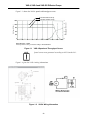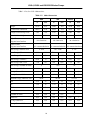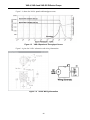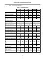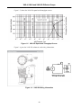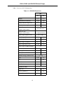
1
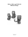
Vacuum Products Division
VHS-4, VHS-6 and
VHS-250
Diffusion Pumps
Part No. 699901024
Revision C
June 2013
INSTRUCTION MANUAL
VHS-4, VHS-6 and VHS-250
Diffusion Pumps
Copyright 2013
Agilent, Inc.
VHS-4, VHS-6 and VHS-250 Diffusion Pumps
Warranty
Products manufactured by Seller are warranted against defects in materials and workmanship for twelve (12) months
from date of shipment thereof to Customer, and Seller’s liability under valid warranty claims is limited, at the option of
Seller, to repair, replacement, or refund an equitable portion of the purchase price of the Product. Items expendable in
normal use are not covered by this warranty. All warranty replacement or repair of parts shall be limited to equipment
malfunctions which, in the sole opinion of Seller, are due or traceable to defects in original materials or workmanship.
All obligations of Seller under this warranty shall cease in the event of abuse, accident, alteration, misuse, or neglect of
the equipment. In-warranty repaired or replaced parts are warranted only for the remaining unexpired portion of the
original warranty period applicable to the repaired or replaced parts. After expiration of the applicable warranty period,
Customer shall be charged at the then current prices for parts, labor, and transportation.
When products are used with toxic chemicals, or in an atmosphere that is dangerous to the health of humans, or is
environmentally unsafe, it will be the responsibility of the Customer to have the product cleaned by an independent
agency skilled and approved in handling and cleaning contaminated materials before the product will be accepted by
Agilent, Inc. for repair and/or replacement.
Reasonable care must be used to avoid hazards. Seller expressly disclaims responsibility for loss or damage caused by
use of its Products other than in accordance with proper operating procedures.
Except as stated herein, Seller makes no warranty, express or implied (either in fact or by operation of law), statutory or
otherwise; and, except as stated herein, Seller shall have no liability under any warranty, express or implied (either in
fact or by operation of law), statutory or otherwise. Statements made by any person, including representatives of Seller,
which are inconsistent or in conflict with the terms of this warranty shall not be binding upon Seller unless reduced to
writing and approved by an officer of Seller.
Disclaimer
Operation and maintenance of this equipment involves serious risk. It is the responsibility of the user to maintain safe
operating conditions at all times. Agilent, Inc. assumes no liability for personal injury or damage resulting from
operation or service of the equipment.
Agilent, Inc. has no control over the use of this equipment and is not responsible for personal injury or damage resulting
from its use. The safe use and disposal of hazardous or potentially hazardous materials of any kind is the sole
responsibility of the user. Observe all WARNINGS and CAUTIONS to minimize the serious hazards involved.
It is the sole responsibility of the users of Agilent, Inc. equipment to comply with all local, state and federal safety
requirements (laws and regulations) applicable to their system. Employ the services of an industrial hygienist and/or a
qualified chemical safety engineer in order to ensure safe installation and use.
Warranty Replacement and Adjustment
All claims under warranty must be made promptly after occurrence of circumstances giving rise thereto, and must be
received within the applicable warranty period by Seller or its authorized representative. Such claims should include
the Product serial number, the date of shipment, and a full description of the circumstances giving rise to the claim.
Before any Products are returned for repair and/or adjustment, written authorization from Seller or its authorized
representative for the return and instructions as to how and where these Products should be returned must be obtained.
Any Product returned to Seller for examination shall be prepaid via the means of transportation indicated as acceptable
by Seller. Seller reserves the right to reject any warranty claim not promptly reported and any warranty claim on any
item that has been altered or has been returned by non-acceptable means of transportation. When any Product is
returned for examination and inspection, or for any other reason, Customer shall be responsible for all damage resulting
from improper packing or handling, and for loss in transit, notwithstanding any defect or non-conformity in the Product.
In all cases, Seller has the sole responsibility for determining the cause and nature of failure, and Seller’s determination
with regard thereto shall be final.
If it is found that Seller’s Product has been returned without cause and is still serviceable, Customer will be notified and
the Product returned at Customer’s expense; in addition, a charge for testing and examination may be made on Products
so returned.
3
VHS-4, VHS-6 and VHS-250 Diffusion Pumps
This page intentionally left blank.
VHS-4, VHS-6 and VHS-250 Diffusion Pumps
Contents
Introduction and Installation.......................................................................................................... 19
Introduction ................................................................................................................................ 19
Pump Specifications .............................................................................................................. 19
Installation .................................................................................................................................. 28
Unpacking ............................................................................................................................ 28
Pump Oil Installation ............................................................................................................ 28
Vacuum System Connections ................................................................................................ 29
Cooling Water Connections .................................................................................................. 29
Electrical Connections ........................................................................................................... 30
Thermal Switch ..................................................................................................................... 31
Operation ......................................................................................................................................... 33
Startup 33
Shutdown ................................................................................................................................... 34
Maintenance and Service ............................................................................................................... 35
General Maintenance 35
Inspection Requirements ............................................................................................................. 35
Cleaning ..................................................................................................................................... 36
VHS-4 and VHS-6 Cold Cap Removal/Installation ....................................................................... 37
VHS-250 Cold Cap Removal/Installation ..................................................................................... 38
Jet Assembly Removal/Installation ............................................................................................... 39
Heater Replacement ................................................................................................................... 42
Pump Fluid Charge ..................................................................................................................... 44
Troubleshooting.............................................................................................................................. 45
Leakage 45
Outgassing .................................................................................................................................. 45
Poor Pump or System Performance ............................................................................................. 46
Replacement Parts.......................................................................................................................... 49
5
VHS-4, VHS-6 and VHS-250 Diffusion Pumps
This page intentionally left blank.
VHS-4, VHS-6 and VHS-250 Diffusion Pumps
Tables
General Hazards 13
Explosive Conditions 15
Pressurization Hazards 16
1-1
Pump Operational Specifications .........................................................................................
1-2
VHS-4 Dimensions ..............................................................................................................
1-3
VHS-6 Dimensions ..............................................................................................................
1-4
VHS-250 Dimensions ..........................................................................................................
4-1
Troubleshooting...................................................................................................................
5-1
VHS-4 Models .....................................................................................................................
5-2
VHS-4 Replacement Parts ....................................................................................................
5-3
VHS-6 Models .....................................................................................................................
5-4
VHS-6 Replacement Parts ....................................................................................................
5-5
VHS-250 Models .................................................................................................................
5-6
VHS-250 Replacement Parts ................................................................................................
7
19
23
25
27
46
49
49
50
51
52
52
VHS-4, VHS-6 and VHS-250 Diffusion Pumps
This page intentionally left blank.
VHS-4, VHS-6 and VHS-250 Diffusion Pumps
Figures
1-1
1-2
1-3
1-4
1-5
1-6
3-1
3-2
3-3
3-4
3-5
3-6
VHS-4 Speed and Throughput Curves ................................................................................... 22
VHS-4 Wiring Information .................................................................................................... 22
VHS-6 Speed and Throughput Curves ................................................................................... 24
VHS-6 Wiring Information .................................................................................................... 24
VHS-250 Speed and Throughput Curves ............................................................................... 26
VHS-250 Wiring Information ................................................................................................ 26
VHS4 and VHS-6 Cold Cap Removal/Installation.................................................................. 37
VHS-250 Cold Cap Removal/Installation............................................................................... 38
VHS-4 Diffusion Pump Jet Assembly ..................................................................................... 40
VHS-6 and 250 Diffusion Pump Jet Assembly ....................................................................... 41
VHS-6 and VHS-250 Heater Mounting ................................................................................. 42
VHS-4 Heater Mounting ....................................................................................................... 43
9
VHS-4, VHS-6 and VHS-250 Diffusion Pumps
This page intentionally left blank.
VHS-4, VHS-6 and VHS-250 Diffusion Pumps
Preface
Instructions for Use
This equipment is designed for use by professionals. Read this instruction manual and any
other additional information supplied by Agilent before operating the equipment. Agilent
will not be held responsible for any events that occur due to non-compliance with these
instructions, improper use by untrained persons, non-authorized interference with the
equipment, or any action contrary to that provided for by specific national standards.
Documentation Standards
This manual uses the following documentation standards:
WARNING
Warnings are for attracting the attention of the operator to a
particular procedure or practice which, if not followed
correctly, could lead to serious injury.
CAUTION
Cautions are displayed before procedures, which if not
followed, could cause damage to the equipment.
NOTE
Notes contain important information.
11
VHS-4, VHS-6 and VHS-250 Diffusion Pumps
Safety
Diffusion Pump Hazards
Designers of systems utilizing diffusion pumps must design out hazards wherever possible.
For hazards that cannot be designed out, warnings, procedures, and instructions on proper
use and servicing are provided. Please use guards, safety features, and interlocks as
recommended.
Refer to the following tables for a list of general hazards and recommended actions, a list of
prohibited actions that can result in explosions, and a list of pressurization hazards that can
result in damage to equipment.
THE INSTALLATION, OPERATION, AND SERVICING OF DIFFUSION PUMPS INVOLVES
ONE OR MORE OF THE HAZARDS LISTED IN THIS SECTION, ANY ONE OF WHICH IN
THE ABSENCE OF SAFE OPERATING PRACTICES AND PRECAUTIONS, COULD
POTENTIALLY RESULT IN DEATH OR SERIOUS HARM TO PERSONNEL.
12
VHS-4, VHS-6 and VHS-250 Diffusion Pumps
General Hazards
Hazard
Suggested Corrective Action
Loss of utility: water and/or electricity
Provide sufficient backup water and power
supply as necessary to effect a safe shutdown
under worst case conditions.
Overpressure in foreline
Provide an interlock to ensure that the power
supply to the pump heater cannot be activated
if the foreline pump is not running and/or the
pressure in foreline is above 0.5 Torr (0.67 mbar).
Overtemperature
Fit temperature sensors and pump fluid level
sensors with feedback to an interlock on the
heater power supply.
Insufficient water flow through main cooling coils Use water flow sensor and feedback to interlock
the heater power supply.
Water trapped between inlet and outlet of
Quick Cool Coil, or liquid nitrogen trapped
between inlet and outlet of liquid nitrogen trap
Provide vent or pressure relief valves for both
Quick Cool Coil and liquid nitrogen trap.
Loss of electrical ground integrity
Incorporate ground fault interrupt circuit into
heater power supply.
Positive pressure in pumping system
Integrate pressure relief valve in vacuum system.
High voltage
Prevent personnel contact with high voltages;
design and attach warnings.
Toxicity and Corrosivity
Toxic and/or corrosive gases must be vented
to a safe location, ensuring adequate dilution or
scrubbing to safe levels, taking all action required
to meet air quality standards.
Explosion
Integrate pressure relief valves in all systems
using pumps 10” or larger in diameter.
Do not use hydrocarbon-based pumping oils.
13
VHS-4, VHS-6 and VHS-250 Diffusion Pumps
Explosion
Operation of the diffusion pump without continuous evacuation below 0.5 Torr (0.67 mbar)
or without coolant, and then introducing a strong oxidizer (such as air), explosive vapors,
powders, or materials which may react with pumping fluids in a hot pump (above 300 °F or
150 °C) can cause an explosion. Such an explosion would violently expel valves and other
hardware, slam open doors that are not designed for appropriate pressure relief, or burst
other components of the vacuum system. Serious injury or death could result from expelled
parts, doors, shrapnel, and shock waves.
Avoid the implementing the following three elements that could result in an explosion:
❑
Fuel
❑
Oxidizer
❑
Ignition
A combination of temperature and pressure can be a source of ignition. Most diffusion
pump fluids, except mercury, are fuels. Hydrocarbon oils are more prone to oxidize and
explode than synthetic silicone-based oil. The oxidizer can be air, which is a strong oxidizer
that is introduced by a leak, deliberately brought in via a process, or inadvertently admitted
by an operator or by a process controller error.
Explosion and Fire from Acetone and Alcohol
Diffusion pumps are typically cleaned with acetone and alcohol. When combined with
air, oxygen, and other oxides, alcohol and most other solvents are very flammable and
explosive. Never permit any trace of these cleaners to remain in or on the pump. Remove
all traces of alcohol and acetone and other cleaners with clean, dry, oil-free compressed air.
Oxygen and other strong oxidizers are even more dangerous than air. Certain conditions
of temperature and pressure can cause a combustible mixture to explode. The larger the
diffusion pump, the greater the risk of explosion and the greater the risk of damage and
injury. Never operate large diffusion pumps utilizing hydrocarbon oils without a complete
safety analysis for the entire system and for the application.
Never operate a large diffusion pump under the conditions listed in the following table.
Any of these situations increases the probability of an explosion.
14
VHS-4, VHS-6 and VHS-250 Diffusion Pumps
Explosive Conditions
Prohibited Action
Explosion-Causing Condition
Do not run pump without cooling water.
Overtemperature
Do not run pump with low level of pump fluid.
Overtemperature
Do not run pump without proper backing or holding pump.
Overpressure
Do not run pump when not evacuated below 0.5 Torr
(0.67 mbar).
Overpressure
Do not admit air to, or rough through, a pump with hot boiler.
Overpressure plus strong oxidizer
Do not open drain or fill plug while pump is under vacuum,
especially when it is hot.
Overpressure plus strong oxidizer
Do not contaminate pump with explosive vapors.
Lower explosive threshold
of gas mixtures
Do not remove, defeat, or override safety counter-measures such Overtemperature, overpressure,
as pressure and thermal switches and valve sequencer interlocks. more combustible mixtures
Do not machine or weld any part of the pump without removing
all oil or solvent residue in pump in large pumps.
Source of ignition
Do not use unsuitable pumping fluid, especially hydrocarbon oil. Lower explosive threshold
of gas mixture
15
VHS-4, VHS-6 and VHS-250 Diffusion Pumps
Pressurization Hazards
Large vacuum pumps and their components are designed for vacuum service. They are not
designed to be pressurized, which can cause them to burst and possibly expel shrapnel at
lethal velocities. Serious accidents have been caused by intentional pressurization of
vacuum systems and their components.
❑
Never pressurize any part of a vacuum system for test or any other purpose.
❑
Always provide pressure relief when designing diffusion pumps into systems and
ensure that pressure relief motion is limited to safe envelopes.
❑
Never permit any of the hazards in the table below to develop.
Pressurization Hazards
Prohibited Action
Result
Do not block inlet or vent of liquid nitrogen trap and lines. LN2 trap and/or lines burst
Do not close isolation valves at inlet and discharge of main Water turns to steam and bursts coils
water cooling coils when pump is reheated.
Do not pressurize the pump body.
Body of pump bursts
Do not make a hole through the vacuum wall.
Loss of structural integrity of wall
Pressure Relief Devices
Systems larger than 10”, such as this pump, must be designed with pressure relief devices to
provide safe pressure relief from internal explosions. Always recognize that safety devices
can fail or malfunction; provide redundant protection by installing devices having different
failure modes, failure mechanisms, and failure causes. Be certain that exhaust duct
materials are capable of withstanding the corrosivity, temperature, and pressure of
exhausted products.
16
VHS-4, VHS-6 and VHS-250 Diffusion Pumps
Dangerous Substances
Chemical Dangers of Acetone and Alcohol
Diffusion pumps are typically cleaned with acetone or alcohol. Acetone, alcohol, and most
other solvents are irritants, narcotics, and depressants, and/or carcinogenic. Their inhalation
and ingestion may produce serious effects. Even absorption through the skin can result in
moderate toxicity.
Ensure that cleaning operations are always performed in large, well-ventilated rooms. The
use of a self-contained breathing apparatus may be necessary depending upon the solvent
type and vapor concentration in surrounding air.
Poisonous and Corrosive Compounds
When pumping poisonous, reactive, and/or corrosive gas, vapors, or chemicals, proper
operation and regeneration do not always ensure that all hazardous materials have been
totally removed.
If hazardous gas, vapors, chemicals, or combustible mixtures are pumped, sufficient
quantities may exist during operation or remain after regeneration to cause severe injury or
death.
Pump Fluids
Overheating the pump fluid, exposing it to air or reactive materials, or overpressurizing it
above the normal operating range (approximately 1 x 10⁻³ Torr / 1.3 x 10⁻³ mbar)
decomposes the fluid and possibly makes it toxic. This is especially true of backstreamed
mechanical pump oils which are more volatile (unstable). Overheating of accidentally
introduced or backstreamed mechanical pump oils cannot be protected against by thermal
switches which are set for diffusion pump oil.
Process Gasses
These gasses are frequently toxic, flammable, corrosive, explosive, or otherwise reactive.
Agilent has no control over the types of gasses passing through your diffusion pump as these
are entirely under the control of the process user and/or the hardware systems integrator.
Since these gasses can cause serious injury or death, it is very important to plumb the
exhaust of the pump to the facility’s hazardous gas exhaust system which incorporates
appropriate filters, scrubbers and similar components to ensure that the exhaust meets all air
and water pollution control regulations.
17
VHS-4, VHS-6 and VHS-250 Diffusion Pumps
High Temperatures
Hot Surfaces
Boiler temperatures reach 530 °F (275 °C) which can cause serious burns. Always ensure
that surfaces have cooled to near room temperature before touching them.
Hot Cooling Water and Steam
The water used to cool the pump can reach scalding temperatures. Touching or rupturing
the cooling surface can cause serious burns. Water left inside Quick Cool Coils from
previous use turns to steam when the pump is reheated. This steam must be allowed to
escape without coming into contact with personnel. Whenever possible, design the water
system with interlock valves so that power cannot be applied to the pump unless water is
flowing in the main cooling coils (not the Quick Cool Coils).
High Voltages
Diffusion pump heaters operate at voltages high enough to kill. Design systems to prevent
personnel contact with high voltages. Securely attach prominent hazard warnings. Always
break the primary circuit to the power supply when direct access to the heater or wiring is
required.
18
VHS-4, VHS-6 and VHS-250 Diffusion Pumps
Section 1. Introduction and Installation
1.1 Introduction
Before unpacking and installing a VHS-4, VHS-6 or VHS-250 diffusion pump, thoroughly
familiarize yourself with this instruction manual and the diffusion pump operational
specifications (Table 1-1). Examine all other technical material supplied in order to gain a
better understanding of the operating principles, limitations, correct application, and
hazards involved with the operation of this equipment.
1.1.1 Pump Specifications
Table 1-1
Power Rating
Pump Operational Specifications
VHS-4: 1450 Watts
VHS-6: 2200 Watts
VHS-250: 2200 Watts
Optimum Operating Range (Torr)
VHS-4 and VHS-6: 1x10⁻³ to < 5x10⁻⁹
(1.3 x 10⁻³ to < 6.6 x 10⁻⁹ mbars)
VHS-250: 7x10⁻⁴ to < 5x10⁻⁹ (9 x 10⁻⁴ to < 6 x 10⁻⁹ mbars)
Maximum Pumping Speed (l/s)
VHS-4: Air – 1200 with std cold cap; 950 with extended cold
cap
Helium –1500 with std cold cap; 1200 with extended
cold cap
VHS-6: Air – 2400 with std cold cap; 1600 with extended cold
cap
Helium –3000 with std cold cap; 2000 with extended
cold cap
VHS-250: Air – 3700 with std cold cap; Helium –4600
Maximum Throughput (Torr-l/s)
VHS-4: 1.2 (1.6 mbar-l/s) in operating range
2.5 (3.2 mbar-l/s) @0.01 Torr
VHS-6: 2.4 (3.2 mbar-l/s) in operating range
3.5 (4.5 mbar-l/s) @0.01 Torr
VHS-250: 2.6 (3.5 mbar-l/s) in operating range
3.5 (4.5 mbar-l/s) @0.01 Torr
Maximum Forepressure
No Load – 0.65 Torr (.87 mbars)
Full Load – 0.55 Torr (.73 mbars)
19
DRAFT 6/18/13
Table 1-1 lists the specifications for the VHS-4, VHS-6 and VHS-250 pumps.
VHS-4, VHS-6 and VHS-250 Diffusion Pumps
Table 1-1
Pump Operational Specifications (Continued)
Backstreaming Rate at Pump Inlet
5x10⁻⁴ mg/cm2/minute (with std cold cap)
Electrical Requirements
120, 208, 240; 50/60 Hz; single phase
Warm-up Time
10 minutes
Cooldown Time
(using Quick Cool Coil)
10 minutes
Fluid Charge
VHS-4: 300 cc
VHS-6 and VHS-250: 500 cc
Cooling Water Requirements
Maximum inlet temperature – 60/80 °F (15 - 26 °C)
Maximum outlet temperature at foreline – 120 °F (48.9 °C)
Flow rate – VHS-4: 0.15 gpm
VHS-6 and VHS-250: 0.25 gpm
DRAFT 6/18/13
Pressure drop across coils
VHS-4: 4 psi
VHS-6 and VHS-250: 15 psi
Backing Pump Size
VHS-4: ≥ 10 cfm for maximum throughput
VHS-6 and VHS-250: 17 cfm for maximum throughput
Recommended Jet Assembly
4-stage, self-aligning, stainless steel
Foreline Baffle
Stacked half moon
Cold Cap
Nickel-plated copper
Water Connections
1/8" FPT
Thermal Switches
Manual reset at 300 °F (149 °C)
Environmental
Maximum ambient temperature 113 °F (45 °C)
Installation
Indoor use, Installation Category 2, Pollution Degree 2
Altitude
6562’ (2000 m)
20
VHS-4, VHS-6 and VHS-250 Diffusion Pumps
Table 1-1
Heater circuit resistance (ohms)
Pump Operational Specifications (Continued)
VHS-4: 1450 watts
120 V – 10
208 V – 29.8
240 V – 39.7
VHS-6 and VHS-250: 2200 watts
Clearance (for heater removal)
6" minimum
Materials
Body, Flanges, Foreline, Baffle – stainless steel
Jet Assembly – stainless steel
Body Cooling Coils – copper
Quick Cooling Coil – stainless steel
Cold Cap – nickel-plated copper
Shipping Weight
VHS-4: 55 pounds
VHS-6 and VHS-250: 75 pounds
21
DRAFT 6/18/13
120 V – 6.5
208 V – 19.6
240 V – 26.1
VHS-4, VHS-6 and VHS-250 Diffusion Pumps
Figure 1-1 shows the VHS-4 speed and throughput curves.
Speed with standard cold cap
1800
5
1200
4
900
3
600
2
300
1
0
10−10
10−9
10−4
10−7
10−10
10−5
10−4
10−3
10−2
10−1
Throughput (Torr-//sec)
Air Speed (//sec)
Speed with extended cold cap
0
DRAFT 6/18/13
INLET PRESSURE — TORR
*Note: Speed curves were generated according to AVS Standards 4.1
Figure 1-1
VHS-4 Speed and Throughput Curves
NOTE
Speed curves were generated according to AVS Standard 4.1.
Figure 1-2 gives the VHS-4 wiring information.
Figure 1-2
VHS-4 Wiring Information
22
VHS-4, VHS-6 and VHS-250 Diffusion Pumps
Table 1-2 lists the VHS-4 dimensions.
VHS-4 Dimensions
ASA
ISO
Conflat
in
mm
in
mm
in
mm
Height
18.05
458
18.05
458
18.05
458
Centerline to Centerline
10.62
270
10.62
270
10.62
270
Flange Face to Flange Face
5.03
128
5.03
128
5.03
128
EIectrlc8I Box Height
8.63
219
8.63
219
8.63
219
Sight Glass,
Degrees from Foreline
Electrical Box,
Degrees from Foreline
90° clockwise
90° clockwise
90° clockwise
30° counterclockwise 30° counterclockwise 30° counterclockwise
Inlet Flange, Nominal Size
4” ASA
ISO -160K
8” CFF
Inlet Flange, OD
9.00
229
7.09
180
7.96
202
Inlet Flange, ID
5.91
150
5.78
147
5.91
150
Inlet Flange, Thickness
0.50
13
0.47
12
0.93
24
Inlet Flange, Bolt Circle
7.50
191
N/A
N/A
7.12
181
Inlet Flange, Number of Holes
8
N/A
20
Inlet Range, Hole Size
0.69
18
N/A
N/A
.33
8
O-ring Groove ID
6.06
154
N/A
N/A
N/A
N/A
O-ring Groove Width
0.18
4
N/A
N/A
N/A
N/A
Foreline Flange, Nominal Size
KF40
KF-40
2¾ CFF
OD
2.16
55
2.16
55
2.73
69
ID
1.38
35
1.38
35
1.38
35
Thickness
0.20
5
0.20
5
1.38
35
Bolt Circle
N/A
N/A
N/A
N/A
2.31
59
Number of Holes
N/A
N/A
N/A
N/A
Hole Size
N/A
N/A
N/A
N/A
0.27
7
O-ring Groove ID
N/A
N/A
N/A
N/A
N/A
N/A
O-ring Groove Width
N/A
N/A
N/A
N/A
N/A
N/A
23
6
DRAFT 6/18/13
Table 1-2
VHS-4, VHS-6 and VHS-250 Diffusion Pumps
Figure 1-3 shows the VHS-6 speed and throughput curves.
DRAFT 6/18/13
Figure 1-3
VHS-6 Speed and Throughput Curves
Figure 1-4 gives the VHS-6 schematic and wiring information.
Figure 1-4
VHS-6 Wiring Information
24
VHS-4, VHS-6 and VHS-250 Diffusion Pumps
Table 1-3 lists the VHS-6 dimensions.
VHS-6 Dimensions
ASA
ISO
Conflat
in
mm
in
mm
in
mm
Height
21.92
557
21.92
557
21.92
557
Centerline to Centerline
13.38
340
13.38
340
13.38
340
Flange Face to Flange Face
8.62
219
8.62
219
8.62
219
EIectrlc8I Box Height
9.12
232
9.12
232
9.12
232
Sight Glass,
Degrees from Foreline
Electrical Box,
Degrees from Foreline
90° clockwise
90° clockwise
90° clockwise
30° counterclockwise 30° counterclockwise 30° counterclockwise
Inlet Flange, Nominal Size
6” ASA
ISO -200K
10” CFF
Inlet Flange, OD
11.00
279
9.45
240
9.97
253
Inlet Flange, ID
7.88
200
7.72
196
7.88
200
Inlet Flange, Thickness
0.75
19
0.47
12
0.96
24
Inlet Flange, Bolt Circle
9.50
241
N/A
N/A
9.12
232
Inlet Flange, Number of Holes
8
N/A
24
Inlet Range, Hole Size
0.81
21
N/A
N/A
.33
8
O-ring Groove ID
8.20
208
N/A
N/A
N/A
N/A
O-ring Groove Width
0.18
4
N/A
N/A
N/A
N/A
Foreline Flange, Nominal Size
1½" ASA
KF-50
33/8" CFF
OD
5.00
127
2.05
75
3.38
86
ID
1.95
50
1.95
50
1.95
50
Thickness
0.63
16
0.24
6
0.62
16
Bolt Circle
3.88
99
N/A
N/A
2.85
72
N/A
N/A
Number of Holes
4
8
Hole Size
0.62
16
N/A
N/A
0.33
8
O-ring Groove ID
2.22
56
N/A
N/A
N/A
N/A
O-ring Groove Width
0.30
8
N/A
N/A
N/A
N/A
25
DRAFT 6/18/13
Table 1-3
VHS-4, VHS-6 and VHS-250 Diffusion Pumps
DRAFT 6/18/13
Figure 1-5 shows the VHS-250 speed and throughput curves.
Figure 1-5
VHS-250 Speed and Throughput Curves
Figure 1-6 gives the VHS-250 schematic and wiring information.
Figure 1-6
VHS-250 Wiring Information
26
VHS-4, VHS-6 and VHS-250 Diffusion Pumps
Table 1-4 lists the VHS-250 dimensions.
Table 1-4
VHS-250 Dimensions
in
mm
Height
22.79
579
Centerline to Centerline
13.38
340
Flange Face to Flange Face
9.56
243
Electrical Box Height
9.12
232
Sight Glass,
Degrees from Foreline
90° clockwise
Electrical Box,
Degrees from Foreline
30° counterclockwise
Inlet Flange, Nominal Size
ISO - 250F
Inlet Flange, OD
13.19
335
Inlet Flange, ID
10.75
273
Inlet Flange, Thickness
0.63
16
Inlet Flange, Bolt Circle
12.205
310
Inlet Flange, Number of Holes
12
Inlet Range, Hole Size
0.44
11
O-ring Groove ID
10.95
278
O-ring Groove Width
0.14
4
Foreline Flange, Nominal Size
1½ ASA
OD
5.00
127
ID
1.88
48
Thickness
0.62
16
Bolt Circle
3.88
99
Number of Holes
4
Hole Size
0.62
16
O-ring Groove ID
2.22
56
O-ring Groove Width
0.30
8
27
DRAFT 6/18/13
ISO
VHS-4, VHS-6 and VHS-250 Diffusion Pumps
1.2 Installation
Installation consists of:
❑
Section 1.2.2 “Unpacking”
❑
Section 1.2.3 “Pump Oil Installation”
❑
Section 1.2.4 “Vacuum System Connections” on page 29
❑
Section 1.2.5 “Cooling Water Connections” on page 29
❑
Section 1.2.6 “Electrical Connections” on page 30
❑
Section 1.2.7 “Thermal Switch” on page 31
1.2.2 Unpacking
When unpacking the pump:
DRAFT 6/18/13
1. Inspect the pump to ensure that no damage has occurred during shipping.
Do not discard any evidence of rough handling; report any damage to the carrier and to
Agilent without delay.
Diffusion pumps are factory-packed to permit prolonged storage in suitably protected
areas without special precautions.
2. Remove flange covers and protective plugs from water connections being careful not to
scratch the inlet and foreline flanges O-ring seal surfaces.
3. Inspect the internal jet assembly. It should be concentric and firmly seated on the
bottom of the diffusion pump and the ejector nozzle must be directly in line with the
foreline.
The location of the jet is controlled by an indexing pin located on the bottom of
the pump.
NOTE
The pump requires no initial cleaning if the required vacuum
level is above 10−6 Torr. For pressure below 10−6 Torr (1.3x10⁻⁶
mbar), follow the cleaning procedure in Section 3.3 “Cleaning”
on page 36.
4. Charge the pump with the diffusion pump oil shipped with the pump.
1.2.3 Pump Oil Installation
The recommended oil charge for the:
❑
VHS-4 is 300 cc
❑
VHS-6 and VHS-250 is 500 cc
❑
Pour the oil is normally into the pump inlet or foreline, or remove the fill plug and
pour it into the fill and drain assembly.
28
VHS-4, VHS-6 and VHS-250 Diffusion Pumps
1.2.4 Vacuum System Connections
WARNING
Utility failure can cause damage to the equipment, overheating,
and explosions. Diffusion pump equipment designers must take
appropriate system design action to protect personnel and
property from possible hazards. Read the safety section at the
beginning of this manual.
1. Install the diffusion pump with the body vertical and plumb.
2. Ensure that the pump inlet mating flange on the system is horizontal within ±1°. The
boiler plate must be horizontal to prevent an uneven fluid level.
Failure to meet this requirement could result in overheating of
the diffusion pump boiler plate.
3. Prepare the inlet and foreline O-rings by wiping them with a clean, lint-free cloth.
A small amount of diffusion pump oil may be used to clean the O-rings.
4. Install the O-rings in the O-ring grooves, being careful not to damage or scratch the
sealing surface.
5. Check the fill and drain plugs for tightness and apply light to medium torque, enough to
compress the O-rings.
6. Using an appropriate lifting apparatus, align the bolt holes of the inlet flange with the
bolt holes of the mating flange.
7. Using the appropriate mounting hardware, tighten the bolts evenly until the O-ring is
compressed and the flanges make light, metal-to-metal contact.
8. Ensure the integrity of the connections: Check the vacuum connections for leaks using a
helium mass spectrometer leak detector before operating the vacuum system.
1.2.5 Cooling Water Connections
1. Connect the inlet water fitting (near the inlet flange at the top of the pump) to a
continuously running water supply at 0.15 gpm (VHS-4) or .25 gpm (VHS-6 and 250)
and at a temperature of 60 to 80 °F.
CAUTION
In the following step, discharge connections must be installed
in accordance with all Federal State and local laws and
regulations.
If the diffusion pump is being cooled by a recirculating water
system:
❑ Ensure the exit water temperature does not exceed 120 °F.
❑ The outlet or discharge (nearest the foreline) should be
connected to an open drain.
29
DRAFT 6/18/13
CAUTION
VHS-4, VHS-6 and VHS-250 Diffusion Pumps
❑ The minimum rating of this system should be 85% of the
maximum power rating of the diffusion pump.
❑ The Quick Cool Coil feed line, located at the boiler plate,
should be controlled by a separate three-way valve (open,
closed, and vent to atmosphere).
2. Connect the quick cool drain to an open drain which is below the inlet connection of
the Quick Cool Coil to ensure that the Quick Cool Coil is completely drained when the
cooling water supply is turned off and the pump is vented to atmosphere.
1.2.6 Electrical Connections
WARNING
Diffusion pump heaters operate at voltages high enough to kill
through electrical shock.
❑ During installation, check the drawings and be sure to attach
all hazard warning and caution labels.
DRAFT 6/18/13
❑ Always break the primary circuit of the power supply when
direct access to the heater or wring is required.
Read the safety section in the front of this manual.
The diffusion pump has been designed to operate at a specific voltage. The voltage is
specified on the label that is mounted on the side of the pump.
1. Verify the heater rating by measuring the resistance of the heater circuit and comparing
it to the values in Table 1-1 on page 19.
2. Make the electrical connections in the junction box located near the foreline. The
electrical supply should not be more than ±5% of the rated voltage.
CAUTION
All electrical connections should be made by qualified
personnel in accordance with all applicable state, local, and/or
industrial codes.
3. Connect the ground earth wire directly to the ground stud. The wire must be terminated
in a double crimp closed loop/ring connector. The connector must be placed over the
ground stud and secured by a lock washer and nut.
4. Connect the two line input wires to terminal positions L1 and L2. For added safety, to
prevent wires from becoming disconnected, secure the two line input wires together
inside the junction box with a tie-wrap, similar to what was done with the heater wires
on the other side of the terminal block.
30
VHS-4, VHS-6 and VHS-250 Diffusion Pumps
1.2.7 Thermal Switch
The pump has been fitted with a manually-resettable thermal switch that is preset at the
factory. This switch is located in a box near the bottom of the pump and provides protection
to the pump in the event of excessive fluid loss, the loss of cooling water, or high inlet
pressure.
WARNING
❑
Failure to properly connect the thermal switch circuit can result
in catastrophic injury to personnel and major damage to the
pump or vacuum system.
Connect the thermal switch in series with the heater.
Reset the thermal switch by pressing the button located at the center of the thermal switch.
Do this only after the root cause of a problem has been determined and the appropriate
corrective action taken.
31
DRAFT 6/18/13
In the event of overtemperature. the thermal switch opens and shut off the power to the
pump.
DRAFT 6/18/13
VHS-4, VHS-6 and VHS-250 Diffusion Pumps
This page intentionally left blank.
VHS-4, VHS-6 and VHS-250 Diffusion Pumps
Section 2. Operation
CAUTION
❑ Before turning on the heater, ensure there is fluid in the pump.
Running the heater without fluid can ruin the heater and
damage the pump.
❑ Do not air-release the pump while the boiler is hot. Most
diffusion pump fluids are heat sensitive and breaks down under
these conditions.
❑ Do not operate the pump without the internal splash baffle or
foreline baffle in place. If the splash baffle is omitted, the pump
may be unstable and operate at a low speed. If the foreline
baffle is omitted, there may be excessive fluid loss.
above 1 mTorr (1.3x10⁻³ mbars). High-pressure operation can
cause excessive backstreaming.
❑ Do not operate the pump heater unless cooling water is
circulating. It causes the pump fluid to overheat.
2.1 Startup
During initial operation of the diffusion pump, a fresh charge of diffusion pump oil may go
through a degassing process. This can result in inlet and foreline pressure fluctuations.
These pressure fluctuations are normal.
1. Visually inspect the sight glass assembly to ensure that the diffusion pump has been
charged with the proper amount of diffusion pump fluid.
When properly filled, the oil level (when the pump is cold) is even with the FULL/COLD
mark on the oil level indicator.
2. Evacuate the diffusion pump (rough pump) with a mechanical backing pump
(customer supplied).
The pressure must be reduced to less than 0.5 Torr (.66 mbars). The backing pump
should remain connected to the foreline of the diffusion pump.
3. Turn on the cooling water supply to the pump body and verify that the cooling water is
not being supplied to the Quick Cool Coil at this time.
4. Turn on the power to the diffusion pump heater.
33
DRAFT 6/18/13
❑ Do not operate the pump for extended periods at inlet pressures
VHS-4, VHS-6 and VHS-250 Diffusion Pumps
5. Monitor inlet and foreline pressures.
During operation of the diffusion pump:
❑
The gas load at the inlet should not exceed the maximum throughput capability of
the pump.
❑
The forepressure should not exceed the specified tolerable forepressure.
2.2 Shutdown
1. Turn off the power to the diffusion pump and continue to back the diffusion pump with
the appropriate mechanical pump.
2. Allow cooling water to flow through the diffusion pump until the pump body
temperature, located just above the boiler plate, has cooled to a temperature of
approximately 130 °F.
DRAFT 6/18/13
After isolating the backing pump, the diffusion pump can be vented to atmosphere.
If faster cooling is desired, the pump can be cooled using the Quick Cool Coil at the
bottom of the diffusion pump.
34
VHS-4, VHS-6 and VHS-250 Diffusion Pumps
Section 3. Maintenance and Service
3.1 General Maintenance
Diffusion pumps generally require little attention when operated correctly. It is advisable to
perform some periodic inspections to ensure trouble-free operation. By performing simple
preventive maintenance, costly downtime can be avoided. A day-to-day log of pump and
system performance helps indicate the condition of the pump and the need for corrective
action.
The frequency of inspections depends on the type of system, its operation, and its use.
The maximum interval between inspections is established on the basis of experience.
Agilent recommends that you examine the following items regularly:
✔ When the pump is cold, check the condition and level of the fluid.
❑
Withdraw a fluid sample through the drain and visually check the level of the fluid
through the sight glass. A slight discoloration of the fluid does not affect
performance.
NOTE
Always use new O-rings when replacing
fill plugs or the sight glass.
Loss of fluid can be caused by any of the following conditions:
❑
Incorrect venting procedures and/or admittance of excessive air or other gas to a
hot pump
❑
Inadequate water cooling
❑
Prolonged operation at inlet pressures above 10−3 Torr (1.33x10⁻³ mbar)
❑
Failure to reinsert the foreline baffle in the pump assembly
✔ Check the total heater power input.
❑
When the pump is cold and the power is off, ensure that the heater is bolted
snugly to the boiler plate.
❑
Verify that all heater terminal connections at the heater and inside the junction
box are tight and in good condition.
35
DRAFT 6/18/13
3.2 Inspection Requirements
VHS-4, VHS-6 and VHS-250 Diffusion Pumps
❑
Ensure that the cooling water flow is adequate and unobstructed. In areas where
the mineral content of the water is high or where there is considerable sediment,
it may be advisable to install water filters.
3.3 Cleaning
Complete cleaning of the pump may be required due to the gradual deterioration of pump
fluids. Removal of the pump from the system is necessary.
To clean the pump:
1. Turn off the power and disconnect the power supply plug.
2. Allow the pump to cool, then turn off the cooling water and disconnect the cooling
lines.
3. Unbolt the inlet flange and foreline connections.
DRAFT 6/18/13
4. Remove the pump from the system.
5. Drain the diffusion pump of all fluid.
6. Remove all O-rings, then remove the cold cap assembly, the jet assembly, and the
foreline baffle from the pump.
7. Thoroughly clean the diffusion pump body interior and the jet assembly using acetone
followed by an isopropyl alcohol rinse.
8. Dry the pump and the jet assembly with clean, dry, oil-free compressed air.
9. Install the foreline baffle, the jet assembly, and the cold cap assembly in the pump body.
❑
Verify that the ejector nozzle is properly aligned with the foreline.
❑
Verify that the cold cap is properly installed on the jet assembly. The space between
the underside of the cold cap and the outside of the jet cap should be uniform.
10. Reinstall the diffusion pump in the system using all new O-rings.
11. Charge the pump with the proper amount of fluid.
12. Reconnect the water cooling lines and the power supply.
13. Evacuate the diffusion pump with the appropriate mechanical pump and turn on the
cooling water.
14. After the pump has been evacuated to a pressure below 0.5 Torr (.66 mbars), turn on the
power to the diffusion pump.
36
VHS-4, VHS-6 and VHS-250 Diffusion Pumps
3.4 VHS-4 and VHS-6 Cold Cap Removal/Installation
To remove the cold cap:
1. Remove the spring (1) (Figure 3-1) attached by round head screw (2), a flat washer (3)
and a lock washer (4). The screw types are:
❑
VHS-4: no. 8-32x3/16
❑
VHS-6: no. 6-32x3/16
2. Loosen the nut (5) holding the cold cap bracket (6) to the copper bar (A) and remove the
cold cap (7) from the top of the jet cap (8).
3. Unscrew the no. 8-32x1/4 socket head cap screw (9) from the top of the ceramic standoff
(10).
4. Remove the ceramic standoff (10) and the no. 8-32x1/2 stud (11).
1. Thread the 8-32 stud (11) into the ceramic bushing (10) until it bottoms (finger tight).
2. Thread the 8-32 hex socket head screw (9) into top of ceramic bushing (10) until it
bottoms.
3. Install the ceramic bushing assembly onto the top of the jet cap (8) by threading stud
(11) into the tapped hole in the top jet cap. Install finger tight.
4. Attach spring clip (1) to cold cap (7) with 6-32 screw (2) and washers (3 and 4) so that
the clip rests on top of sleeve (12).
5. Lower the cold cap assembly carefully onto the top of the jet cap assembly (8). The
ceramic bushing fits in sleeve (12) and the clamp bar (6) straddles the body bar (A).
6. Lower the cold cap until the horizontal portion of the spring clip (1) touches the head of
screw (9). Ensure that the clearance between the cold cap and the top jet cap is even
around the periphery and that the cold cap assembly is level with the pump inlet flange.
7. Carefully tighten the captive bolt (5) ensuring that there is no strain on the ceramic
bushing and no shift in the position of the cold cap.
7
12 1
2, 3, 4
5
6
9
10
11
8
A
Figure 3-1
VHS4 and VHS-6 Cold Cap Removal/Installation
37
DRAFT 6/18/13
To install the cold cap:
VHS-4, VHS-6 and VHS-250 Diffusion Pumps
3.5 VHS-250 Cold Cap Removal/Installation
To remove the cold cap:
1. Remove the spring (J) attached by the 6-32x3/16 round head screw (H), a flat washer and
a lock washer (Figure 3-2).
2. Loosen the nuts (L) holding the cold cap bracket (E) to the copper bar (C) and remove
the cold cap (B) from the top of the jet cap (A).
3. Unscrew the no. 8-32x1/4 socket head cap screw (G) from the top of the ceramic
standoff (D).
4. Remove the ceramic standoff (D) and the no. 8-32x1/2 stud (F).
To install the cold cap:
DRAFT 6/18/13
1. Thread the 8-32 stud (F) into the ceramic bushing (0) until it bottoms (finger tight).
2. Thread the 8-32 hex socket head screw (G) into top of ceramic bushing (0) until it
bottoms.
3. Install the ceramic bushing assembly onto the top of the jet cap (A) by threading stud (F)
into the tapped hole in the top jet cap. Install finger tight.
4. Attach spring clip (J) to cold cap (8) with 6-32 screw (H) so that the clip rests on top of
sleeve (K).
5. Lower the cold cap assembly carefully onto the top of the jet cap assembly (A). The
ceramic bushing fits in sleeve (K) and the clamp bars (E) straddle the body bar (C).
6. Lower the cold cap until the horizontal portion of the spring clip (J) touches the head of
screw (G). Ensure that the clearance between the cold cap and the top jet cap is even
around the periphery and that the cold cap assembly is level with the pump inlet flange.
7. Carefully tighten the captive bolts (L) ensuring that there is no strain on the ceramic
bushing and no shift in the position of the cold cap.
Figure 3-2
VHS-250 Cold Cap Removal/Installation
38
VHS-4, VHS-6 and VHS-250 Diffusion Pumps
3.6 Jet Assembly Removal/Installation
To remove the jet assembly:
1. Remove the cold cap from the pump (Figure 3-3).
2. Unscrew the top cap from the jet assembly.
3. Lift out each section of the jet assembly, being careful not to dent or otherwise damage
the jet assembly during disassembly or cleaning.
4. Remove the splash baffle from the pump.
To install the jet assembly:
1. Place the splash baffle in the bottom of the pump and verify that it is located in the outer
boiler groove.
3. Assemble the remaining stages of the jet.
❑
Verify that all the stages are firmly seated.
❑
Verify that all the drip shields are in place.
4. Install the cold cap assembly.
39
DRAFT 6/18/13
2. Insert the jet base, making sure the ejector is aligned with the foreline and that the slot in
the jet base locks onto the alignment pin.
VHS-4, VHS-6 and VHS-250 Diffusion Pumps
Jet Cap
Jet Plug
Inner Rod
2nd Stage Drip Shield
3rd Stage Jet
3rd Stage Drip Shield
DRAFT 6/18/13
Jet Tube Assembly
Jet Base
Ejector
4.00 Flat
Splash Baffle
Boiler Plate
Jam Nut
Figure 3-3
VHS-4 Diffusion Pump Jet Assembly
40
DRAFT 6/18/13
VHS-4, VHS-6 and VHS-250 Diffusion Pumps
Figure 3-4
VHS-6 and 250 Diffusion Pump Jet Assembly
41
VHS-4, VHS-6 and VHS-250 Diffusion Pumps
3.7 Heater Replacement
Refer to Figure 3-5 (VHS-6 and VHS-250) and Figure 3-6 (VHS-4) for this procedure:
1. Turn off the power to the diffusion pump and disconnect the power supply.
2. Remove the heater cover and the insulation from the bottom of the diffusion pump.
3. Label the heater wires for proper location during installation.
4. Disconnect the terminal leads.
Use two wrenches when loosening (one on each nut) to prevent excessively torquing
and possibly breaking the heater terminals.
5. Remove the nut holding the heater clamp.
6. Lower the entire heater unit from the pump and replace the defective heater.
DRAFT 6/18/13
7. Coat the boiler stud with an anti-seize compound such as FEL-PRO C5A or common
milk of magnesia.
8. Support the heater unit by the heater clamp, line up the hole with the boiler stud, and
push the unit up against the boiler plate.
9. Finger-tighten the nut to hold it in place.
10. Tighten the heater clamp bolt to a torque of 250 inch-pounds.
11. Replace the heater insulation and cover.
Heater Element
647306125 2200 W, 120 V
647306175 2200 W, 208 V
647306225 2200 W, 240 V
Figure 3-5
VHS-6 and VHS-250 Heater Mounting
42
VHS-4, VHS-6 and VHS-250 Diffusion Pumps
Heater Element
Figure 3-6
VHS-4 Heater Mounting
43
DRAFT 6/18/13
647304205 1450 W, 120 V
647304210 1450 W, 208 V
647304250 1450 W, 240 V
VHS-4, VHS-6 and VHS-250 Diffusion Pumps
3.8 Pump Fluid Charge
The recommended fluid charge is:
❑
300 cc for the VHS-4
❑
500 cc for VHS-6 and VHS-240
The fluid charge will gradually be depleted through use, but the pump will continue to
operate normally.
When the charge is reduced to approximately 60% of the initial fill amount, the boiler plate
temperature may begin to rise. Under this condition, the thermal switch, when properly
connected, is designed to open the heater circuit.
To add pump fluid:
DRAFT 6/18/13
1. Turn off power to the pump and allow the pump to cool until the temperature of the
pump body (measured 1" above the heater skirt) has cooled to 130 °F.
2. Turn off the backing pump.
3. Vent the pump to atmosphere.
4. Loosen and remove the fill plug located at the top of the sight glass assembly.
5. Add pump fluid until the fluid level is even with the FULL/COLD mark on the
sight glass.
6. Replace the O-ring in the fill plug and lubricate it with pump fluid.
7. Install the fill plug and tighten it moderately.
8. Evacuate the diffusion pump and start the pump as according to Section 2.1 “Startup”
on page 33.
44
VHS-4, VHS-6 and VHS-250 Diffusion Pumps
Section 4. Troubleshooting
4.1 Leakage
❑
Inlet and foreline connections
❑
Drain and fill plugs
❑
Other compression fittings, such as high vacuum gauges in the system
❑
Threaded connections, such as foreline gauge
4.2 Outgassing
High vacuum systems, even without external leakage, can also exhibit high gas loads due to
outgassing from internal surfaces or processes. The pressure in the system is a result of gas
load divided by pumping speed (P = Q/S). If the gas load (Q) exceeds the maximum
throughput capability of the diffusion pump, the diffusion pump will not function and the
pumping action will essentially be performed by the mechanical backing pump.
To estimate gas load:
After evacuation, isolate the system from all pumps and measure the rate of pressure
rise. The gas load created by the system can be estimated as:
Q = V x ∆P
∆t
Where:
V is the isolated volume
∆P is the pressure rise, and
∆t is the time period of measurement
45
DRAFT 6/18/13
Analysis of general operational experience with diffusion pumps indicates that certain
locations are more prone to vacuum leaks. The following locations should be checked first
if leakage is the suspected cause of poor system performance:
VHS-4, VHS-6 and VHS-250 Diffusion Pumps
4.3 Poor Pump or System Performance
Before proceeding with a step-by-step troubleshooting program, check the performance and
accuracy of the vacuum gauges used on the system. Table 4-1 shows the most frequent
faults, their probable causes, and specific repair actions required for each.
Table 4-1
Symptom
Poor system pressure
DRAFT 6/18/13
Poor ultimate pressure
Troubleshooting
Probable Cause
Repair Action
Leak in system — virtual or real. Locate and repair.
High process gas load.
Measure gas load,
and eliminate the cause.
System dirty.
Clean system to reduce
outgassing.
Contaminated pump fluid.
Examine, clean pump,
and replace fluid.
Low heat input.
Check voltage.
Check for continuity, burned out
element, poor thermal contact.
Slow pumpdown (prolonged
cycle after checking gas load
conditions)
Inadequate cooling water flow.
Check water pressure. Check
tubing for obstructions or
backpressure.
Excessive or too cold
cooling water.
Check temperature, adjust flow.
High forepressure.
Check for leak in foreline, poor
mechanical pump performance,
breakdown of mechanical pump
fluid.
Water in Quick Cool Coil.
Check and remove water.
Low heat input.
Check heaters.
Low oil level.
Add oil.
Malfunctioning pump assembly
Improperly located jets.
Damaged jet system.
Check and repair or replace.
46
VHS-4, VHS-6 and VHS-250 Diffusion Pumps
Symptom
Inlet pressure surges
High chamber contamination
Pump will not start
Troubleshooting (Continued)
Probable Cause
Repair Action
Incorrect heater voltage.
Check and correct voltage.
Fluid outgassing.
Condition pump fluid by
operating pump for a few hours.
Leak in system ahead of
pump inlet.
Check and correct.
Forepressure too high.
Check for leak in foreline, poor
mechanical pump performance,
breakdown of pump fluid, and
incorrect valve operation.
Prolonged operation at high
throughput at pressure above
10−3 Torr (1.33x10⁻³ mbar).
Review operating procedures.
Improper system operation
air-release procedures.
Review operating procedures
Safety circuits and/or protective
devices prevent contactor from
staying closed.
Check utilities, flow switches,
interlocks, and thermostat
operation.
47
DRAFT 6/18/13
Table 4-1
DRAFT 6/18/13
VHS-4, VHS-6 and VHS-250 Diffusion Pumps
This page intentionally left blank.
VHS-4, VHS-6 and VHS-250 Diffusion Pumps
Section 5. Replacement Parts
Table 5-1 lists the VHS-4 models.
Table 5-2 lists the VHS-4 replacement parts available from Agilent.
Table 5-1
VHS-4 Models
Part Number
Pump
Voltage
ASA
ISO
Conflat
Standard cold cap
120 V
86460301
L6256301
L6188301
Extended cold cap
120 V
86460311
L6256311
L6188311
Standard cold cap
208 V
86460306
L6256306
L6188306
Extended cold cap
208 V
86460316
L6256316
L6188316
Standard cold cap
240 V
86460302
L6256302
L6188302
Extended cold cap
240 V
86460312
L6256312
L6188312
Table 5-2
VHS-4 Replacement Parts
Part Number
Description
86488301
Standard Cold Cap Assembly
F6898301
Extended Cold Cap Assembly
L8908301
Sight Glass Repair Kit
F4785301
Jet Assembly
F4780 301
Splash Baffle
86754 301
Foreline Baffle Assembly
642906025
Switch
699006025
Standoff, ceramic insulating, Cold Cap
647304205
120 V / 1450 watt Heater Element
647304210
208 V / 1450 watt Heater Element
647306250
240 V / 1450 watt Heater Element
656179100
Wire, No. 10 stranded, nickel
648056680
Lugs, Replacement, nickel
49
DRAFT 6/18/13
Flange Type
VHS-4, VHS-6 and VHS-250 Diffusion Pumps
Table 5-2
VHS-4 Replacement Parts (Continued)
88164301
Heater Clamp
Commercial
Heater Clamp Nut, 31/48-16, Hex, stainless steel
694492156
Baffle Retaining Ring
K0377183
O-Ring Kit includes:
❑ 3 Butyl inlet flange O-ring, Parker No. 2-258
❑ 10 Viton fill and drain O-rings (old style), Parker No. 2-112
❑ 10 Viton fill and drain O-rings (new style, Parker No. 2-113
❑ 1 Sight glass O-ring, Parker No. 2-226
DRAFT 6/18/13
❑ 1 PTFE gasket
K6948301
NEOVAC SY Diffusion Pump Fluid (1000 cc)
695474005
DC-704 Diffusion pump Fluid (500 cc)
695475005
DC-70S Diffusion Pump Fluid (500 cc)
695405005
Santovac 5 Diffusion Pump Fluid (500 cc)
86715001
Spring, Cold Cap
Commercial
Screw, Rd hd machine, no. 8-32x31/416, stainless steel
Commercial
Stud, no. 8-32 x 1~2, stainless steel
Commercial
Screw, Socket hd cap, no. 8-32x11/44, stainless steel
Table 5-3 lists the VHS-6 models.
Table 5-4 lists the VHS-6 replacement parts available from Agilent.
Table 5-3
VHS-6 Models
Part Number
Flange Type
Pump
Voltage
ASA
ISO
Conflat
Standard cold cap
120 V
85826301
L6193301
L6200301
Extended cold cap
120 V
85826311
L6193311
L6200311
Standard cold cap
208 V
85826306
L6193306
L6200306
Extended cold cap
208 V
85826316
L6193316
L6200316
Standard cold cap
240 V
85826302
L6193302
L6200302
Extended cold cap
240 V
85826312
L6193312
L6200312
50
VHS-4, VHS-6 and VHS-250 Diffusion Pumps
Table 5-4
VHS-6 Replacement Parts
Description
86488301
Standard Cold Cap Assembly
F6455301
Extended Cold Cap Assembly
F3365301
Jet Assembly
F3373301
Splash Baffle
L9172301
Foreline Baffle Assembly
642906025
Thermoswitch
699006025
Standoff, ceramic insulating, Cold Cap
647306125
120 V / 2200 watt Heater Element
647306175
208 V / 2200 watt Heater Element
647306225
240 V / 2200 watt Heater Element
656179100
Wire, No. 10 stranded, nickel
648056680
Lugs, Replacement, nickel
86087001
Heater Insulator
86086301
Heater Clamping Plate
86088301
Heater Cover Plate
L8998001
Heater Insulating Blanket
L8997001
Heater Cover
K0377184
O-Ring Kit includes:
❑ 3 Butyl inlet flange O-ring, Parker No. 2-267
❑ 3-Butyl-N foreline flange O-ring, Parker No. 2-332
❑ 10 Viton fill and drain O-rings (old style), Parker No. 2-112
❑ 10 Viton fill and drain O-rings (new style, Parker No. 2-113
❑ 1 PTFE gasket
❑ 1 Sight glass O-ring, Parker No. 2-226
K6948301
NEOVAC SY Diffusion Pump Fluid (1000 cc)
695474005
DC-704 Diffusion pump Fluid (500 cc)
695475005
DC-70S Diffusion Pump Fluid (500 cc)
695405005
Santovac 5 Diffusion Pump Fluid (500 cc)
86715001
Spring, Cold Cap
Commercial
Screw, Rd hd machine, no. 6-32x3/16, stainless steel
51
DRAFT 6/18/13
Part Number
VHS-4, VHS-6 and VHS-250 Diffusion Pumps
Table 5-4
VHS-6 Replacement Parts (Continued)
Commercial
Washer, flat, no. 6, stainless steel
Commercial
Washer, lock, no. 6, stainless steel
Commercial
Stud, no. 8-32 x 1/2, stainless steel
Commercial
Screw, Socket hd cap, no. 8-32x1/4, stainless steel
Table 5-5 lists the VHS-250 models.
Table 5-6 lists the VHS-250 replacement parts available from Agilent.
Table 5-5
VHS-250 Models
Part Number
DRAFT 6/18/13
Flange Type
Pump
Voltage
ISO
Standard cold cap
120 V
K0543301
Standard cold cap
208 V
K0543306
Standard cold cap
240 V
K0543302
Table 5-6
VHS-250 Replacement Parts
Part Number
Description
F9584301
Standard Cold Cap Assembly
F9548301
Jet Assembly
F3373301
Splash Baffle
L9172301
Foreline Baffle Assembly
642906025
Thermoswitch
699006025
Standoff, ceramic insulating, Cold Cap
647306125
120 V / 2200 watt Heater Element
647306175
208 V / 2200 watt Heater Element
647306225
240 V / 2200 watt Heater Element
656179100
Wire, No. 10 stranded, nickel
648056680
Lugs, Replacement, nickel
86087001
Heater Insulator
86086301
Heater Clamping Plate
52
VHS-4, VHS-6 and VHS-250 Diffusion Pumps
Table 5-6
VHS-250 Replacement Parts (Continued)
86088301
Heater Cover Plate
L8998001
Heater Insulating Blanket
L8997001
Heater Cover
K0377178
O-Ring Kit includes:
❑ 3 Butyl inlet flange O-ring, Parker No. 2-332
❑ 3-Butyl-N foreline flange O-ring, Parker No. 2-379
❑ 10 Viton fill and drain O-rings (old style), Parker No. 2-112
❑ 10 Viton fill and drain O-rings (new style, Parker No. 2-113
❑ 1 PTFE gasket
K6948301
NEOVAC SY Diffusion Pump Fluid (1000 cc)
695474005
DC-704 Diffusion pump Fluid (500 cc)
695475005
DC-70S Diffusion Pump Fluid (500 cc)
695405005
Santovac 5 Diffusion Pump Fluid (500 cc)
86715001
Spring, Cold Cap
Commercial
Screw, Rd hd machine, no. 6-32x3/16, stainless steel
Commercial
Washer, flat, no. 6, stainless steel
Commercial
Washer, lock, no. 6, stainless steel
Commercial
Stud, no. 8-32 x 1/2, stainless steel
Commercial
Screw, Socket hd cap, no. 8-32x1/4, stainless steel
53
DRAFT 6/18/13
❑ 1 Sight glass O-ring, Parker No. 2-226
DRAFT 6/18/13
VHS-4, VHS-6 and VHS-250 Diffusion Pumps
This page intentionally left blank.
VHS-4, VHS-6 and VHS-250 Diffusion Pumps
Reque
st for Return Health and
Safety Certification
Vacuum Products Division
Instructions for returning products
Dear Customer:
Please follow these instructions whenever one of our products needs to be returned.
1) Complete the attached Request for Return form and send it to Agilent Technologies (see below), taking particular care to identify
all products that have pumped or been exposed to any toxic or hazardous materials.
2) After evaluating the information, Agilent Technologies will provide you with a Return Authorization (RA) number via email or fax,
as requested.
Note: Depending on the type of return, a Purchase Order may be required at the time the Request for Return is submitted. We
will quote any necessary services (evaluation, repair, special cleaning, eg).
3) Important steps for the shipment of returning product:
x Remove all accessories from the core product (e.g. inlet screens, vent valves).
x Prior to shipment, drain any oils or other liquids, purge or flush all gasses, and wipe off any excess residue.
x If ordering an Advance Exchange product, please use the packaging from the Advance Exchange to return the defective
product.
x Seal the product in a plastic bag, and package product carefully to avoid damage in transit. You are responsible for loss or
This page intentionally left blank.
damage in transit.
x Agilent Technologies is not responsible for returning customer provided packaging or containers.
x Clearly label package with RA number. Using the shipping label provided will ensure the proper address and RA number
are on the package. Packages shipped to Agilent without a RA clearly written on the outside cannot be accepted and will
be returned.
4) Return only products for which the RA was issued.
5) Product being returned under a RA must be received within 15 business days.
6) Ship to the location specified on the printable label, which will be sent, along with the RA number, as soon as we have received
all of the required information. Customer is responsible for freight charges on returning product.
7) Return shipments must comply with all applicable Shipping Regulations (IATA, DOT, etc.) and carrier requirements.
RETURN THE COMPLETED REQUEST FOR RETURN FORM TO YOUR NEAREST LOCATION:
EUROPE:
Fax:
00 39 011 9979 330
Fax Free: 00 800 345 345 00
Toll Free: 00 800 234 234 00
[email protected]
NORTH AMERICA:
PACIFIC RIM:
Fax:
1 781 860 9252
Toll Free: 800 882 7426, Option 3
[email protected]
please visit our website for individual
office information
http://www.DJLOHQW.com
Pg 1/3
VHS-4, VHS-6 and VHS-250 Diffusion Pumps
Vacuum Products Division
Request for Return Form
(Health and Safety Certification)
Please read important policy information on Page 3 that applies to all returns.
1) CUSTOMER INFORMATION
Company Name:
Contact Name:
Tel:
Email:
Fax:
Customer Ship To:
Customer Bill To:
Europe only: VAT reg. Number:
USA/Canada only:
2) PRODUCT IDENTIFICATION
Product Description
Agilent P/N
Agilent S/N
Taxable
Non-taxable
Original Purchasing Reference
3) TYPE OF RETURN (Choose one from each row and supply Purchase Order if requesting a billable service)
3A.
Non-Billable
3B.
Exchange
Billable
Repair
New PO # (hard copy must be submitted with this form):
Upgrade
Consignment/Demo
Calibration
Evaluation
Return for Credit
4) HEALTH and SAFETY CERTIFICATION This page intentionally left blank.
AGILENT TECHNOLOGIES CANNOT ACCEPT ANY PRODUCTS CONTAMINATED WITH BIOLOGICAL OR EXPLOSIVE HAZARDS,
RADIOACTIVE MATERIAL, OR MERCURY AT ITS FACILITY.
Call Agilent Technologies to discuss alternatives if this requirement presents a problem.
The equipment listed above (check one):
HAS NOT pumped or been exposed to any toxic or hazardous materials. OR
HAS pumped or been exposed to the following toxic or hazardous materials. If this box is checked, the following
information must also be filled out. Check boxes for all materials to which product(s) pumped or was exposed:
Toxic
Corrosive
Reactive
Flammable
Explosive
Biological
Radioactive
List all toxic/hazardous materials. Include product name, chemical name, and chemical symbol or formula:
________________________________________________________________________________________________________
NOTE: If a product is received at Agilent which is contaminated with a toxic or hazardous material that was not disclosed, the customer will be held responsible for all
costs incurred to ensure the safe handling of the product, and is liable for any harm or injury to Agilent employees as well as to any third party occurring as a result of
exposure to toxic or hazardous materials present in the product.
Print Name:
Authorized Signature: ……………………….
Date:
5) FAILURE INFORMATION:
Failure Mode (REQUIRED FIELD. See next page for suggestions of failure terms):
Detailed Description of Malfunction: (Please provide the error message)
Application (system and model):
I understand and agree to the terms of Section 6, Page 3/3.
Print Name:
Authorized Signature: ……………………….
Pg 2/3
Date:
VHS-4, VHS-6 and VHS-250 Diffusion Pumps
Vacuum Products Division
Request for Return Form
(Health and Safety Certification)
Please use these Failure Mode to describe the concern about the product on Page 2.
APPARENT DEFECT/MALFUNCTION
- Does not start
- Does not spin freely
- Does not reach full speed
- Mechanical Contact
- Cooling defective
- Bad feedthrough
TURBO PUMPS and TURBO CONTROLLERS
POSITION
PARAMETERS
Power:
- Noise
- Vertical
Current:
- Vibrations
-Horizontal
Temp 1:
-Leak
-Upside-down
-Overtemperature
-Other:
Temp 2:
-Clogging
………………….
OPERATING TIME:
ION PUMPS/CONTROLLERS
- Poor vacuum
- Main seal leak
Rotational Speed:
Inlet Pressure:
Foreline Pressure:
Purge flow:
VALVES/COMPONENTS
- Bellows leak
- Vacuum leak
- High voltage problem
- Solenoid failure
- Damaged flange
- Error code on display
- Other
- Damaged sealing area
-Other
- Cannot calibrate
LEAK DETECTORS
-No zero/high backround
INSTRUMENTS
- Gauge tube not working
- Display problem
- Vacuum system unstable
- Cannot reach test mode
- Communication failure
- Degas not working
- Failed to start
- Other
- Error code on display
- Other
SCROLL AND ROTARY VANE PUMPS
This
page
- Pump doesn’t start
- Noisy pump
(describe)
DIFFUSION PUMPS
intentionally
left blank.
- Heater failure
- Electrical problem
- Doesn’t reach vacuum
- Over temperature
- Doesn’t reach vacuum
- Cooling coil damage
- Pump seized
- Other
- Vacuum leak
- Other
Section 6) ADDITIONAL TERMS
Please read the terms and conditions below as they apply to all returns and are in addition to the Agilent
Technologies Vacuum Product Division – Products and Services Terms of Sale.
x
Customer is responsible for the freight charges for the returning product. Return shipments must comply with all
applicable Shipping Regulations (IATA, DOT, etc.) and carrier requirements.
x
Customers receiving an Advance Exchange product agree to return the defective, rebuildable part to Agilent Technologies
within 15 business days. Failure to do so, or returning a non-rebuildable part (crashed), will result in an invoice for the
non-returned/non-rebuildable part.
x
Returns for credit toward the purchase of new or refurbished Products are subject to prior Agilent approval and may incur
a restocking fee. Please reference the original purchase order number.
x
Units returned for evaluation will be evaluated, and a quote for repair will be issued. If you choose to have the unit
repaired, the cost of the evaluation will be deducted from the final repair pricing. A Purchase Order for the final repair price
should be issued within 3 weeks of quotation date. Units without a Purchase Order for repair will be returned to the
customer, and the evaluation fee will be invoiced.
x
A Special Cleaning fee will apply to all exposed products per Section 4 of this document.
x
If requesting a calibration service, units must be functionally capable of being calibrated.
Pg 3/3
VHS-4, VHS-6 and VHS-250 Diffusion Pumps
This page intentionally left blank.
Service & Support
North America
Agilent Technologies
121 Hartwell Avenue
Lexington, MA 02421 USA
Tel.: +1 781 861 7200
Toll-Free: +1 800 882 7426
Fax: +1 781 860 5437
[email protected]
Benelux
Agilent Technologies Netherlands B.V.
Herculesweg 8
4338 PL Middelburg The Netherlands
Tel: +31 118 671570
Fax: +31 118 671569
Toll free: 00 800 234 234 00
China
Agilent Technologies (China) Co. Ltd
No.3, Wang Jing Bei Lu, Chao Yang District, Beijing, 100102 China Tel.: +86 (10)
6439 7888
Fax: +86 (10) 6439 1318
Toll-Free: 800 820 8266
[email protected]
France
Agilent Technologies France
7 avenue des Tropiques
Z.A. de Courtaboeuf - B.P. 12
91941 Les Ulis cedex France
Tel.: +33 (0) 1 69 86 38 84
Fax: +33 (0) 1 69 86 29 88
Toll free: 00 800 234 234 00
[email protected]
Germany & Austria
Agilent Technologies
Lyoner Str. 20
60 528 Frankfurt am Main Germany
Tel.: +49 69 6773 43 2230
Fax: +49 69 6773 43 2250
Toll free: 00 800 234 234 00
This information is subject to change
without notice.
© Agilent Technologies, Inc., 2012
Published in USA, December, 2012
India
Agilent Technologies India Pvt. Ltd.
G01. Prime corporate Park,
230/231, Sahar Road,
Opp. Blue Dart Centre,
Andheri (East), Mumbai – 400 099. India
Tel: +91 22 30648287/8200
Fax: +91 22 30648250
Toll Free: 1800 113037
[email protected]
Italy
Agilent Technologies Italia S.p.A.
via F.lli Varian 54
10040 Leini, (Torino) ITALY
Tel.: +39 011 997 9111
Fax: +39 011 997 9350
Toll-Free: 00 800 234 234 00
[email protected]
[email protected]
Japan
Agilent Technologies Japan, Ltd.
8th Floor, Sumitomo Shibaura Building
4-16-36 Shibaura Minato-ku
Tokyo 108 JAPAN
Tel.: +81 3 5232 1253
Toll-Free: 0120 655 040
Fax: +81 3 5232 1710
[email protected]
Korea
Agilent Technologies
Shinsa 2nd Bldg. 2F
966-5 Daechi-dong
Kangnam-gu, Seoul KOREA 135-280
Tel.: +82 2 3452 2455
Toll-Free: 080 222 2452
Fax: +82 2 3452 2451
[email protected]
Singapore
Agilent Technologies Singapore Pte. Ltd
No.1 Yishun Avenue 7 Singapore 768923
Tel: +65 6215 8045
Fax : +65 6754 0574
Toll-Free: 1 800 2762622
[email protected]
Southeast Asia
Agilent Technologies Sales Sdn Bhd
Unit 201, Level 2 uptown 2,
2 Jalan SS21/37, Damansara Uptown
47400 Petaling Jaya, Selangor, Malaysia
Tel : +603 7712 6106
Fax: +603 6733 8121
Toll-Free: 1 800 880 805
[email protected]
Taiwan
Agilent Technologies Taiwan Limited
20 Kao-Shuang Rd., Pin-Chen City, 324
Taoyuan Hsien, Taiwan, R.O.C. Tel. +886
34959281
Toll Free: 0800 051 342
[email protected]
UK & Ireland
Agilent Technologies
6 Mead Road
Oxford Industrial Park
Yarnton, Oxford OX5 1QU UK
Tel.: +44 (0) 1865 291570
Fax: +44 (0) 1865 291571
Toll free: 00 800 234 234 00
[email protected]
Learn more:
www.agilent.com/chem/vacuum