1
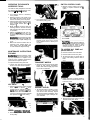
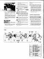
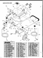
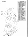
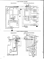
ISr
WINDSOR INDUSTRIES, INC.. 1351 W . Stanford Ave.. Englewood, CO 80110 USA 303/762-1600
FAX 3031762-0617
INSPECTION
Carefully unpack and inspect your extractor for shipping damage. Each unit
is operated and thoroughly inspected
before shipping, and any damage is the
responsibility of the carrier, who should
be notified immediately.
ELECTRICAL
This extractor operates on a standard
15 amp 115 volt AC circuit.‘ Voltages
below 105 volts or above 125 volts could
cause serious damage to motors. Wiring
diagram is mounted inside handle control panel of machine.
‘230volt 50Hz model available.
WARNING: To avoid electric shock:
1. use inaoors only.
2. To reduce risk of fire, do not use
volatile.substances.
3. Use only cleaners intended for floor
and carpet application.
GROUNDING INSTRUCTIONS
To protect the operator from electric
shock, this machine must be grounded
while in use. The machine is equipped
with an approved three-conductor power
cord and three-prong grounding type
plug to fit the proper grounding type receptacle. The vacuum power cord has a
plug as shown in Fig. A. If a receptacle
connected to the electrical ground as
shown in Fig. A is not available use an
adapter as shown in Fig. C. The adapter
must be connected to an electrical
ground in the electrical outlet, using
metal screw shown in Fig. B.
GROUNOED
OUTLET BOX
GROUMOING ”
PIN
IA)
POAPTER
TEMPERATURE THAT EXCEEDS
150’F (65’C)
NOTE: Make sure dome is seated correctly to ensure proper vacuum seal.
CHEMICALS
The internal parts of the pump used in
the extractor is suitable for use with
most carpet cleaning chemicals. But it
is susceptible to chemical attach from
some cleaning substances, such as
hydrocarbon solvents and chlorinated
bleaches. These noncompatible materials are not of the type normally used
for carpet cleaning.
SUITABLE
NONCOMPATIBLE
CHEMICALS
CHEMICALS
Aldehydes
Alkalis
Aromatic Hydrocarbons
Clorox II Bleach’
Butyls
Defoaming Agents
Carbon Tetrachloride
Detergents
Clorox‘
Hydroxides
Chlorinated Bleaches
Oxygen Bleaches
Chlorinated Hydrocarbons
Soaps
Ski-Put Fabric Softener Lysol’
Methyls (MEK)
Vinegar
White Monday Bleach’ Perchlorethylene (perc)
Phenols
Trichlorethylene
‘Aegisterea Trademark
a
OPERATING THE ADM
NOTE: Vacuum the carpet and make
sure it is cleared of surface debris before cleaning with the ADM.
NOTE: Attach strain relieflcord retainer
to power cord.
1. Make loop in power
cord approximately
12” from t w i s t lock
receptacle end.
2 Slue cord loop through
slot in retainer and over
retainer arm. Pull slack
cord back through slot
to secure. Attach retainer to handle.
3. Release cam-locking device located
on lower right of handle and lower
handle to comfortable operating position. Re-set cam-lock on handle.
NOTE: ADM cleans by pulling backwards over the carpet.
Dlaaram 1
EXTENSION CORDS
If an extension cord is used, the wire
size must be at least one size larger
than the power cord on the machine:
The ADM is equipped with a 50 ft. 14/3
power cord.
FILLING THE ADM
1. Remove clear dome from upper tank.
Do not remove the two vacuum hoses.
NOTE: Dome can be set securely between handle uprights when handle
is in Operating position.
2. Lift upper recovery tank from machine
and set aside.
3. Use a clean bucket to fill solution
tank with hot water. Add a nonfoaming concentrate for use in hot
water extractors at the proportions
noted on the container.
CAUT/ON:
To avoid possible dlstortlon of polyethylene solution/
recovery tanks, 00 NOT USE WATER
2
[n”‘i
Diagram 2
a. Brush adjustment lever
b. Solution nipple
c. Solution valve
d. Handle locking lever
e. Solution tank drain hose
4. Adjust brush to proper cleaning position by using lever located at lower
back of the motor housing. Start at
No. 1 “new brush” (black) position.
If more carpet pile agitation is desired,
lower brush setting one position at a
time. (See Diagram 2)
Black
‘TI Red
5. Check to be sure that spray manifold
valve is set on “Carpet Spray” position (See Diagram 3) and that brush
motor circuit breaker button is in (see
Diagram 4).
Diagram 3
pi
BRUSH SWITCH
CONTINUOU
PUMP SWITC
ACCESSITOOL
Diagram 4
CIRCUIT BREAKER
INTERMITTENTP
SWITCH PANEL
6. Tilt machine bacK on rear wheels
until brush is off the floor. Turn on
vacuum and brush motors.
NOTES:
1. Starting the machine with dry brush
resting on the carpet may trip brush
circuit breaker.
2. The vacuum motor is also protected by a circuit breaker. The breaker
will only trip under conditions of
an over-full recovery tank.
abuse
-
7. Lower machine to floor. Dispense
solution by using either the “continuous flow” swltch for large, open
areas or the “intermittent solution”
button for cleaning in smaller, more
confined areas. Walking backwards,
move the extractor over the area to
be cleaned. The extractor’s brush
assistance should allow the machine
to be moved quickly and easily over
the carpet. Remember to turn SOlUtlOn
off about six inches before the end
of each cleaning pass.
8. As you work, check to see if there is
a foam build up in the recovery bucket.
If there is, turn the machine off and
add the recommended amount of defoaming compound to the recovery
tank. Never put defoamer In solution
tank!
WARNING: An overflow of foam
into the vacuum intake can damage
the vac motor. Always be aware of
the waste water level in the recovery
tank. When it is about three-quarters
full, turn off the machine, remove the
dome and lift off the recovery tank to
empty. The tank has a convenient
carrying handle and a built-In handgrip on the underside.
9. When the extractor runs out of Clean.
lng solution (this can be easily detected by streaking and incomplete
cleaning of the carpet, or by looking
at spray manifold from side of machine) turn off the machine, remove
the dome and recovery bucket, and
re-fill the clean solution tank. Replace the recovery tank and dome.
Turn the extractor back on and continue cleaning.
10. Ventilate area after carpet has been
cleaned. Keep children and pets away
and do not walk on carpet until it is
thoroughly dry.
SWITCH CONTROL PANEL
OPERATING THE ADM WITH
ACCESSORY TOOLS
1. Remove screws holding rear panel.
Repair or replace switches as req uired.
The ADM is easily adapted for use with
the following Windsor accessory tools;
DHT-UPH3 SW - SFW SWIPRO.
-
-
1. Turn solution valve to “Accessory
Tool” position.
2. Remove recovery hose (white cuff)
from ADM dome and insert vacuum
hose for accessory tool in its place.
3. Attach solution hose from accessory
tool to brass solution nipple on lower
back of ADM chassis. (See “8” in
Diagram 1)
4. Make sure that solution tank has
cleaning solution and that recovery
tank and dome are in place and ready
for operation.
5. Switch on ADM’s vacuum and contlnous solution switches only. Use
accessory tools as with any standard
extractor.
WARNING: Do not switch on brush
switch when operating the ADM with
accessory tools. Carpet damage may
occur.
6. Make sure that the solution valve is
returned to the “Carpet Spray” position before using the ADM ,again
for self-contained carpet cleaning.
2. Tilt machine back on handle and remove brush pulley guard.
I
BRUSH SWITCH
VAC SWITCH
,
i
CIRCUIT BREAKER
3. Remove shaft retaining screws and
washers from each end of brush
shaft. Replace brush or bearings as
required.
CONTINUOUS
PUMP SWITCH
I
I
I
INTERMITTENT PUMP SWITCH
SWITCH PANEL
CAUTION:
When replacing switches,
make sure wire leads are connected
to proper terminals. Refer to wiring
diagram located on back panel (or
service manual) for assistance.
TO ACCESS VAC, PUMP and
BRUSH MOTOR
MAINTENANCE INSTRUCTIONS
FOR ADM
WARNING: Remove machine power
1. Remove solution from both tanks.
2. Remove dome and recovery tank.
3. Tilt machine back on handle and remove nuts holding solution tank to
base.
cord from electrical source before making any adjustments or repairs to the
machine. Only qualified maintenance
personnel are to perform repairs.
To adjust handle locking cam lever
TRANSPORT WHEELS
1. Loosen cam lever and hand tighten
knob on cam lever rod as required.
1. Remove screw and hub cap and slide
wheel off axle. Before reinstalling
wheel, clean axle and apply light coating of silicone lubricant.
4. Return machine to upright position.
Raise tank and remove solution inlet
hose from pump.
VAC SHOE
9
1. Remove allen screws holding parallel
arms. Repair or replace vac shoe,
parallel arms or spacers as needed.
NOTE When reinstalling vac shoe,
make sure the wave washers are floating and not pinched between parallel
arm spacers and vac shoe casting.
SUPPORT ROLLER
1. Tilt machine back on handte. Loosen
lock nuts on each end of roller axle
and remove roller assembly. Repair
as required. Before reinstalling, clean
axle and apply a light coating of silicone lubricant.
5. Remove (2) vacuum hoses from tube
bracket and lay tank aside.
BRUSH ASSEMBLYIBEARING
1. Remove belt guard and ‘‘roll” belt off
motor pulley.
3
2. Tilt machine back on handle. Remove
exhaust deflector and Hex retaining
nut from PVC muffler. Repair or
replace as required.
VAC MOTOR
1. Remove hose from exhaust horn on
motor.
SOLENOID & SOLUTION VALVES
2. Remove (2) screws holding vac exhaust deflector. set aside.
3. Tilt machine back on handle. Remove
(2) bolts holding vac motor mounting
bracket to base. Return machine to
upright position. Disconnect wire
leads ar?d remove vac motor.
4. To inspect motor brushes, remove
brush holder assembly. Brushes
should be replaced when worn to 318
inch or after about 750 operating
hours. After second brush replacement, the armature commutator
should be checked for pitting and
concentricity. Vac motors can be repaired but such repairs should be
made by a qualified motor repair shop.
1. Remove recovery and solution tanks.
2. Remove auxiliary solution Outlet
nipple.
3. Remove solution valve lever.
4. Remove (2) screws holding valve
clamp chassis.
5. Lift out valve asm. and disconnect
solution hoses. Repair as required.
NOTE: The solenoid valve can be disassembled for cleaning when positive
shut-off is interrupted and valve leaks
through tee jets.
6. Remove hex nut at top of valve and
lift off coil assembly.
7. Use spanner wrench or small punch
and hammer to remove plunger body.
Remove lint and soap residue from
pIunger.
CAUTION: When re-installing valve
make sure arrow is pointed in the direction of solution flow.
sff.
A. HEX NUT
0. PLUNGER BODY
C. WASHER
F. PLUNGER
0. VALVE BODY
MANIFOLD ASSEMBLY
1. Remove pump from chassis to access
solution outlet hose.
2. Remove hose from hosebarb.
3. Tilt machine back on handle. Remove
(2) screws holding manifold to chassis.
Remove manifold and repair as rerequired.
SPRAY JETS
To prevent clogged jets due to alkaline
build-up, the spray system should be
flushed with 1 or 2 gallons of clean hot
water at the end of each day. The machine
is equipped with "quick change" jets
that can be easily removed for cleaning.
To remove - push jet in and rotate 1/4
turn. Wash jets and blow dry. Do not
use pins or wire to remove obstruction
as this will change spray pattern.
."--A
PUMP ASSEMBLY
1. Disconnect pump motor leads. Remove (4) screws holding pump to
chassis. Disconnect solution hoses
from pump head and lift out pump.
Refer to pump drawing for replacement parts.
CAUTION:
When replacin
VAC EXHAUST MUFFLER
1. Remove exhaust hose from muffler
elbow.
hose-
barbs on pump head-DO NO? OVER-
TIGHTEN-as this could crack intake
and exhaust ports in pump head.
WARNING: The internal solution
hoses are encased in an outer hose to
protect the electrical component parts
in the unlikely event a solution hose
should rupture. Replace hoses exactly
as originally supplied.
4
BRUSH DRIVE MOTOR
1. Remove exhaust hose from vac motor.
2. Disconnect motor lead wires.
3. Move brush adjustment lever to lowest
position and tilt machine back on
handle.
4. Remove (4) motor retaining bolts.
2. Inspect and clean filter screen in
3.
4.
5.
8.
solution tank.
Flush pumping system with 1 to 3
gallons of clean, hot water.
Rinse recovery tank with clean water.
Check for and remove any lint or
debris around brush and vac.shoe.
Check spray jets and clean solenoid
valve i f required.
NOTE: Always store ADM with bruall
In “store” position.
b Apply silicone lubricant to solution
nipple.
b Periodically inspect all hoses, electrical cables, filters and connections
on your machine. Frayed or cracked
hoses should be repaired or replaced
to eliminate vacuum or solution pressure loss. Because the electrical
cable will lie on wet carpet at times,
the cable must be well insulated and
cable connector screws kept tight.
If the cable insulation is broken or
frayed, repair or replace it immediately. Don’t take chances with an
electrical fire or shock.
PERIODIC MAINTENANCE
5. Return machine to upright position
and lift out motor. Repair or replace
as required.
NOTE: When reinstalling motor, make
sure motor pulley is in line with brush
pulley. Use straight edge for alignment i f needed. After assembly run
machine on carpet to check for belt
slippage - move motor rearward to
tighten belt.
DAILYIREGULAR
MAINTENANCE
WARNING: Before
making any adjustments or repairs, unplug machine
from electrical source.
1. Empty unused cleaning solution
using clear plastic hose located on
lower back of solution tank.
b Twice a month, flush a white vinegar
solution (one quart vinegar to two
gallons of water) or anti-browning
solution (mixed as directed) through
the extractor. This will prevent build
up of alkaline residue in the system.
b Check sliding handle lock for excessive looseness, and hand tighten knob
on left side of handle as required.
b If spray jets become clogged, remove
the spray tips, wash them thoroughly,
and blow dry.
NOTE: Do not use pins, wire, etc. to
clean nozzles as this could destroy
spray pattern.
b If spray jets drip after the pump is
turned off, sclenoid valve may need
to be cleaned.
PROTECT FROM FREEZING
If it becomes necessary to store in temperatures that could drop below 40” F,
the pumping system, hoses and valves
must be protected from freezing with a
methyl hydrate window washer antifreeze solution. Do not use ethylene
glycol or cooling system antifreezes.
1. Add a gallon or two of window washer
antifreeze to the supply tank, turn on
pump switch and spray until the antifreeze solution fills the solution lines.
2. Drain out the leftover antifreeze from
the supply tank. Always allow the unit
to reach room temperatures before
filling with hot water or operating.
PUMP
I
PUMP PARTS LIST
I
5
56
VAC & PUMP ASSEMBLY
I(EY
PARTNO. DESCRIPTION
ONLY
KEY
PARTNO. ~ R I P f l O N
1 MY
PMTNO. DESCRIPTION
-
...-.
BRUSH HOUSING & MOTOR ASSEMBLY
7
BRUSH HOUSING & MOTOR P R H S LIST
UI
runm. ~~~lllni~ll
-
7
.
HANDLE/CONTROL
llcl
rmm. aascntmo*
PANEL ASM.
TANKS PARTS LIST
TANK ASSEMBLY
n
9
115 VOLT WIRING DIAGRAMS
Handle Control Panel Section
Chassis Section
VACUUM SWITCH
0
K
,I
INTERMITTENT
SPRAV SWITCH
BRvyl
SWITCH
CIRCUIT BREAUER
OUzIll
230 VOLT WIRING DIAGRAMS
Chassis Section
P
BRUSH
MOTOR
10
2
2
3
3
q
5
3
.-.
WINDSOR LIMITED WARRANTY
WINDSOR warrants to the original purchaserluser that this product is free from
defects in workmanship and materials
under normal use and service for a period
of one year from date of purchase. WINDSOR will at its option, repair or replace
without charge, except for transportation
costs, parts that fail under normal use
and service when operated and ,maintained in accordance with the applicable
operation and instruction manuals. This
warranty does not apply to normal wear,
or to items whose life is dependent on
their use and care, such as cords,
switches, hoses, rubber parts, electric
motor parts, etc.
This limited warranty is in lieu of all other
warranties, expressed or implied, and
releases WINDSOR from all other obligations and liabilities. It is applicable only
in the U.S.A. and Canada, and is extended
only to the original user/purchaser of
this product. WINDSOR is not responsible
for costs for repairs performed by persons other than those specifically
authorized by WINDSOR. This warranty
does not apply to damage from transportation, alterations by unauthorized
persons, misuse or abuse of the equipment, use of noncompatible chemicals,
or damage to property, or loss of income
due to malfunctioning of the product.
If a difficulty develops with this machine,
you should contact the dealer from
whom it was Durchased.
0
0
..
c
8
2
8