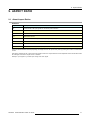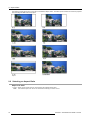
1
HOME CINEMA
CINEVERSUM SYSTEM
R9010090
OWNERS MANUAL
Cine VERSUM 120
01102003
R5976667/00
Barco nv Home Cinema
Noordlaan 5, B-8520 Kuurne
Phone: +32 56.36.84.30
Fax: +32 56.36.88.62
E-mail: [email protected]
Visit us at the web: www.homecinema.barco.com
Printed in Taiwan
Changes
Barco provides this manual ’as is’ without warranty of any kind, either expressed or implied, including but not limited to the implied warranties or merchantability and fitness for a particular purpose. Barco may make improvements and/or changes to the product(s) and/or the
program(s) described in this publication at any time without notice.
This publication could contain technical inaccuracies or typographical errors. Changes are periodically made to the information in this
publication; these changes are incorporated in new editions of this publication.
Copyright ©
All rights reserved. No part of this document may be copied, reproduced or translated. It shall not otherwise be recorded, transmitted or
stored in a retrieval system without the prior written consent of BARCO.
Trademarks
Brand and product names mentioned in this manual may be trademarks, registered trademarks or copyrights of their respective holders.
All brand and product names mentioned in this manual serve as comments or examples and are not to be understood as advertising for
the products or their manufactures.
Federal Communication Commission (FCC Statement)
This equipment has been tested and found to comply with the limits for a class B digital device, pursuant to Part 15 of the FCC rules.
These limits are designed to provide reasonable protection against harmful interference when the equipment is operated in a residential
environment. This equipment generates, uses, and can radiate radio frequency energy and, if not installed and used in accordance with the
instruction manual, may cause harmful interference to radio communications. Operation of this equipment in a residential area is likely to
cause harmful interference in which case the user is encouraged to try to correct the interference by one or more of the following measures.
Introduction to the user :
If this equipment does cause interference to radio or television reception, the user may try to correct the interference by one or more of the
following measures :
•
Re-orientation of the receiving antenna for the radio or television.
•
Relocate the equipment with respect to the receiver.
•
Plug the equipment into a different outlet so that the equipment and receiver are on different branch circuits.
•
Fasten cables connectors to the equipment by mounting screws.
The use of shielded cables is required to comply within the limits of Part 15 of FCC rules and EN55022.
Guarantee and Compensation
Barco provides a guarantee relating to perfect manufacturing as part of the legally stipulated terms of guarantee. On receipt, the purchaser
must immediately inspect all delivered goods for damage incurred during transport, as well as for material and manufacturing faults Barco
must be informed immediately in writing of any complaints.
The period of guarantee begins on the date of transfer of risks, in the case of special systems and software on the date of commissioning,
at latest 30 days after the transfer of risks. In the event of justified notice of compliant, Barco can repair the fault or provide a replacement
at its own discretion within an appropriate period. If this measure proves to be impossible or unsuccessful, the purchaser can demand a
reduction in the purchase price or cancellation of the contract. All other claims, in particular those relating to compensation for direct or
indirect damage, and also damage attributed to the operation of software as well as to other services provided by Barco, being a component
of the system or independent service, will be deemed invalid provided the damage is not proven to be attributed to the absence of properties
guaranteed in writing or due to the intent or gross negligence or part of Barco.
If the purchaser or a third party carries out modifications or repairs on goods delivered by Barco, or if the goods are handled incorrectly,
in particular if the systems are commissioned operated incorrectly or if, after the transfer of risks, the goods are subject to influences not
agreed upon in the contract, all guarantee claims of the purchaser will be rendered invalid. Not included in the guarantee coverage are
system failures which are attributed to programs or special electronic circuitry provided by the purchaser, e.g. interfaces. Normal wear as
well as normal maintenance are not subject to the guarantee provided by Barco either.
The environmental conditions as well as the servicing and maintenance regulations specified in the this manual must be complied with by
the customer.
Table of contents
TABLE OF CONTENTS
1. Safety Instructions . . . . . . . . . . . . . . . . . . . . . . . . . . . . . . . . . . . . . . . . . . . . . . . . . . . . . . . . . . . . . . . . . . . . . . . . . . . . . . . . . . . . . . . . . . . . . . . . . . 3
1.1 General Safety Instructions . . . . . . . . . . . . . . . . . . . . . . . . . . . . . . . . . . . . . . . . . . . . . . . . . . . . . . . . . . . . . . . . . . . . . . . . . . . . . . . . . . . . . . . . . . . . . . . . . . . . . . . . . . . . .
1.2 Module Related Safety Instructions . . . . . . . . . . . . . . . . . . . . . . . . . . . . . . . . . . . . . . . . . . . . . . . . . . . . . . . . . . . . . . . . . . . . . . . . . . . . . . . . . . . . . . . . . . . . . . . . . . . .
1.2.1 Cine VERSUM 120 . . . . . . . . . . . . . . . . . . . . . . . . . . . . . . . . . . . . . . . . . . . . . . . . . . . . . . . . . . . . . . . . . . . . . . . . . . . . . . . . . . . . . . . . . . . . . . . . . . . . . . . . . . . . . . .
1.2.2 Cine VERSUM Master . . . . . . . . . . . . . . . . . . . . . . . . . . . . . . . . . . . . . . . . . . . . . . . . . . . . . . . . . . . . . . . . . . . . . . . . . . . . . . . . . . . . . . . . . . . . . . . . . . . . . . . . . . .
3
3
3
4
2. System Configuration . . . . . . . . . . . . . . . . . . . . . . . . . . . . . . . . . . . . . . . . . . . . . . . . . . . . . . . . . . . . . . . . . . . . . . . . . . . . . . . . . . . . . . . . . . . . . . 5
2.1 The Video Distribution Solution. . . . . . . . . . . . . . . . . . . . . . . . . . . . . . . . . . . . . . . . . . . . . . . . . . . . . . . . . . . . . . . . . . . . . . . . . . . . . . . . . . . . . . . . . . . . . . . . . . . . . . . . . 5
2.2 Overview of the System . . . . . . . . . . . . . . . . . . . . . . . . . . . . . . . . . . . . . . . . . . . . . . . . . . . . . . . . . . . . . . . . . . . . . . . . . . . . . . . . . . . . . . . . . . . . . . . . . . . . . . . . . . . . . . . . 5
3. Overview User’s Controls. . . . . . . . . . . . . . . . . . . . . . . . . . . . . . . . . . . . . . . . . . . . . . . . . . . . . . . . . . . . . . . . . . . . . . . . . . . . . . . . . . . . . . . . . . 7
3.1
3.2
3.3
3.4
Cine VERSUM Master . . . . . . . . . . . . . . . . . . . . . . . . . . . . . . . . . . . . . . . . . . . . . . . . . . . . . . . . . . . . . . . . . . . . . . . . . . . . . . . . . . . . . . . . . . . . . . . . . . . . . . . . . . . . . . . . . . 7
Cine VERSUM 120 . . . . . . . . . . . . . . . . . . . . . . . . . . . . . . . . . . . . . . . . . . . . . . . . . . . . . . . . . . . . . . . . . . . . . . . . . . . . . . . . . . . . . . . . . . . . . . . . . . . . . . . . . . . . . . . . . . . . . 7
Remote Control . . . . . . . . . . . . . . . . . . . . . . . . . . . . . . . . . . . . . . . . . . . . . . . . . . . . . . . . . . . . . . . . . . . . . . . . . . . . . . . . . . . . . . . . . . . . . . . . . . . . . . . . . . . . . . . . . . . . . . . . . 8
Remote Control operation . . . . . . . . . . . . . . . . . . . . . . . . . . . . . . . . . . . . . . . . . . . . . . . . . . . . . . . . . . . . . . . . . . . . . . . . . . . . . . . . . . . . . . . . . . . . . . . . . . . . . . . . . . . . . 10
3.4.1 General . . . . . . . . . . . . . . . . . . . . . . . . . . . . . . . . . . . . . . . . . . . . . . . . . . . . . . . . . . . . . . . . . . . . . . . . . . . . . . . . . . . . . . . . . . . . . . . . . . . . . . . . . . . . . . . . . . . . . . . . . . 10
3.4.2 Battery Insertion in the Remote Control . . . . . . . . . . . . . . . . . . . . . . . . . . . . . . . . . . . . . . . . . . . . . . . . . . . . . . . . . . . . . . . . . . . . . . . . . . . . . . . . . . . . . . . . 11
3.4.3 Visualization of commands. . . . . . . . . . . . . . . . . . . . . . . . . . . . . . . . . . . . . . . . . . . . . . . . . . . . . . . . . . . . . . . . . . . . . . . . . . . . . . . . . . . . . . . . . . . . . . . . . . . . . . 13
4. Switching On/Off the Cine Versum System. . . . . . . . . . . . . . . . . . . . . . . . . . . . . . . . . . . . . . . . . . . . . . . . . . . . . . . . . . . . . . . . . . . . 15
4.1 Brief introduction . . . . . . . . . . . . . . . . . . . . . . . . . . . . . . . . . . . . . . . . . . . . . . . . . . . . . . . . . . . . . . . . . . . . . . . . . . . . . . . . . . . . . . . . . . . . . . . . . . . . . . . . . . . . . . . . . . . . . . . 15
4.2 Upon first startup . . . . . . . . . . . . . . . . . . . . . . . . . . . . . . . . . . . . . . . . . . . . . . . . . . . . . . . . . . . . . . . . . . . . . . . . . . . . . . . . . . . . . . . . . . . . . . . . . . . . . . . . . . . . . . . . . . . . . . . 15
4.3 Switching the system between OPERATION and STANDBY . . . . . . . . . . . . . . . . . . . . . . . . . . . . . . . . . . . . . . . . . . . . . . . . . . . . . . . . . . . . . . . . . . . . . . . . 16
4.3.1 From OPERATION mode to STANDBY mode . . . . . . . . . . . . . . . . . . . . . . . . . . . . . . . . . . . . . . . . . . . . . . . . . . . . . . . . . . . . . . . . . . . . . . . . . . . . . . . . . 16
4.3.2 From STANDBY mode to OPERATION mode . . . . . . . . . . . . . . . . . . . . . . . . . . . . . . . . . . . . . . . . . . . . . . . . . . . . . . . . . . . . . . . . . . . . . . . . . . . . . . . . . 17
4.4 Switching the system between STANDBY and ECONOMIC Standby . . . . . . . . . . . . . . . . . . . . . . . . . . . . . . . . . . . . . . . . . . . . . . . . . . . . . . . . . . . . . . . 17
4.4.1 From STANDBY mode to Economic STANDBY. . . . . . . . . . . . . . . . . . . . . . . . . . . . . . . . . . . . . . . . . . . . . . . . . . . . . . . . . . . . . . . . . . . . . . . . . . . . . . . . 18
4.4.2 From Economic STANDBY mode to STANDBY. . . . . . . . . . . . . . . . . . . . . . . . . . . . . . . . . . . . . . . . . . . . . . . . . . . . . . . . . . . . . . . . . . . . . . . . . . . . . . . . 18
4.5 Switching the system OFF completely and BACK to Operation mode. . . . . . . . . . . . . . . . . . . . . . . . . . . . . . . . . . . . . . . . . . . . . . . . . . . . . . . . . . . . . . . 18
4.5.1 Turning OFF the system from Operation mode . . . . . . . . . . . . . . . . . . . . . . . . . . . . . . . . . . . . . . . . . . . . . . . . . . . . . . . . . . . . . . . . . . . . . . . . . . . . . . . . 19
4.6 Turning ON the system from total OFF mode. . . . . . . . . . . . . . . . . . . . . . . . . . . . . . . . . . . . . . . . . . . . . . . . . . . . . . . . . . . . . . . . . . . . . . . . . . . . . . . . . . . . . . . . . 19
5. Direct source selection. . . . . . . . . . . . . . . . . . . . . . . . . . . . . . . . . . . . . . . . . . . . . . . . . . . . . . . . . . . . . . . . . . . . . . . . . . . . . . . . . . . . . . . . . . . . 21
5.1 From standby mode. . . . . . . . . . . . . . . . . . . . . . . . . . . . . . . . . . . . . . . . . . . . . . . . . . . . . . . . . . . . . . . . . . . . . . . . . . . . . . . . . . . . . . . . . . . . . . . . . . . . . . . . . . . . . . . . . . . . 21
5.2 Return to standby mode . . . . . . . . . . . . . . . . . . . . . . . . . . . . . . . . . . . . . . . . . . . . . . . . . . . . . . . . . . . . . . . . . . . . . . . . . . . . . . . . . . . . . . . . . . . . . . . . . . . . . . . . . . . . . . . 22
6. Image Control . . . . . . . . . . . . . . . . . . . . . . . . . . . . . . . . . . . . . . . . . . . . . . . . . . . . . . . . . . . . . . . . . . . . . . . . . . . . . . . . . . . . . . . . . . . . . . . . . . . . . . . 23
6.1
6.2
6.3
6.4
Brightness Control . . . . . . . . . . . . . . . . . . . . . . . . . . . . . . . . . . . . . . . . . . . . . . . . . . . . . . . . . . . . . . . . . . . . . . . . . . . . . . . . . . . . . . . . . . . . . . . . . . . . . . . . . . . . . . . . . . . . . 23
Contrast Control. . . . . . . . . . . . . . . . . . . . . . . . . . . . . . . . . . . . . . . . . . . . . . . . . . . . . . . . . . . . . . . . . . . . . . . . . . . . . . . . . . . . . . . . . . . . . . . . . . . . . . . . . . . . . . . . . . . . . . . . 23
Color (Saturation) Control . . . . . . . . . . . . . . . . . . . . . . . . . . . . . . . . . . . . . . . . . . . . . . . . . . . . . . . . . . . . . . . . . . . . . . . . . . . . . . . . . . . . . . . . . . . . . . . . . . . . . . . . . . . . . 24
Tint control . . . . . . . . . . . . . . . . . . . . . . . . . . . . . . . . . . . . . . . . . . . . . . . . . . . . . . . . . . . . . . . . . . . . . . . . . . . . . . . . . . . . . . . . . . . . . . . . . . . . . . . . . . . . . . . . . . . . . . . . . . . . . 25
7. Picture in Picture . . . . . . . . . . . . . . . . . . . . . . . . . . . . . . . . . . . . . . . . . . . . . . . . . . . . . . . . . . . . . . . . . . . . . . . . . . . . . . . . . . . . . . . . . . . . . . . . . . . 27
7.1 Turning On/Off the Picture in Picture . . . . . . . . . . . . . . . . . . . . . . . . . . . . . . . . . . . . . . . . . . . . . . . . . . . . . . . . . . . . . . . . . . . . . . . . . . . . . . . . . . . . . . . . . . . . . . . . . . 27
7.2 Selecting Input Source for PIP Window . . . . . . . . . . . . . . . . . . . . . . . . . . . . . . . . . . . . . . . . . . . . . . . . . . . . . . . . . . . . . . . . . . . . . . . . . . . . . . . . . . . . . . . . . . . . . . . 28
7.3 Function keys for Picture in Picture . . . . . . . . . . . . . . . . . . . . . . . . . . . . . . . . . . . . . . . . . . . . . . . . . . . . . . . . . . . . . . . . . . . . . . . . . . . . . . . . . . . . . . . . . . . . . . . . . . . 28
8. Lens and Lamp manipulations. . . . . . . . . . . . . . . . . . . . . . . . . . . . . . . . . . . . . . . . . . . . . . . . . . . . . . . . . . . . . . . . . . . . . . . . . . . . . . . . . . . 31
8.1 Lens adjustment . . . . . . . . . . . . . . . . . . . . . . . . . . . . . . . . . . . . . . . . . . . . . . . . . . . . . . . . . . . . . . . . . . . . . . . . . . . . . . . . . . . . . . . . . . . . . . . . . . . . . . . . . . . . . . . . . . . . . . . 31
8.1.1 Access to controls . . . . . . . . . . . . . . . . . . . . . . . . . . . . . . . . . . . . . . . . . . . . . . . . . . . . . . . . . . . . . . . . . . . . . . . . . . . . . . . . . . . . . . . . . . . . . . . . . . . . . . . . . . . . . . . 31
8.1.2 Focus adjustment . . . . . . . . . . . . . . . . . . . . . . . . . . . . . . . . . . . . . . . . . . . . . . . . . . . . . . . . . . . . . . . . . . . . . . . . . . . . . . . . . . . . . . . . . . . . . . . . . . . . . . . . . . . . . . . 32
8.1.3 Horizontal shift. . . . . . . . . . . . . . . . . . . . . . . . . . . . . . . . . . . . . . . . . . . . . . . . . . . . . . . . . . . . . . . . . . . . . . . . . . . . . . . . . . . . . . . . . . . . . . . . . . . . . . . . . . . . . . . . . . . 32
8.1.4 Vertical shift. . . . . . . . . . . . . . . . . . . . . . . . . . . . . . . . . . . . . . . . . . . . . . . . . . . . . . . . . . . . . . . . . . . . . . . . . . . . . . . . . . . . . . . . . . . . . . . . . . . . . . . . . . . . . . . . . . . . . . 33
8.1.5 Zoom. . . . . . . . . . . . . . . . . . . . . . . . . . . . . . . . . . . . . . . . . . . . . . . . . . . . . . . . . . . . . . . . . . . . . . . . . . . . . . . . . . . . . . . . . . . . . . . . . . . . . . . . . . . . . . . . . . . . . . . . . . . . . 34
8.2 Lamp . . . . . . . . . . . . . . . . . . . . . . . . . . . . . . . . . . . . . . . . . . . . . . . . . . . . . . . . . . . . . . . . . . . . . . . . . . . . . . . . . . . . . . . . . . . . . . . . . . . . . . . . . . . . . . . . . . . . . . . . . . . . . . . . . . . 34
8.2.1 Access controls. . . . . . . . . . . . . . . . . . . . . . . . . . . . . . . . . . . . . . . . . . . . . . . . . . . . . . . . . . . . . . . . . . . . . . . . . . . . . . . . . . . . . . . . . . . . . . . . . . . . . . . . . . . . . . . . . . 35
8.2.2 Lamp mode . . . . . . . . . . . . . . . . . . . . . . . . . . . . . . . . . . . . . . . . . . . . . . . . . . . . . . . . . . . . . . . . . . . . . . . . . . . . . . . . . . . . . . . . . . . . . . . . . . . . . . . . . . . . . . . . . . . . . . 35
8.2.3 Lamp power . . . . . . . . . . . . . . . . . . . . . . . . . . . . . . . . . . . . . . . . . . . . . . . . . . . . . . . . . . . . . . . . . . . . . . . . . . . . . . . . . . . . . . . . . . . . . . . . . . . . . . . . . . . . . . . . . . . . . 36
9. Aspect Ratio. . . . . . . . . . . . . . . . . . . . . . . . . . . . . . . . . . . . . . . . . . . . . . . . . . . . . . . . . . . . . . . . . . . . . . . . . . . . . . . . . . . . . . . . . . . . . . . . . . . . . . . . . 37
9.1 About Aspect Ratios . . . . . . . . . . . . . . . . . . . . . . . . . . . . . . . . . . . . . . . . . . . . . . . . . . . . . . . . . . . . . . . . . . . . . . . . . . . . . . . . . . . . . . . . . . . . . . . . . . . . . . . . . . . . . . . . . . . 37
9.2 Selecting an Aspect Ratio . . . . . . . . . . . . . . . . . . . . . . . . . . . . . . . . . . . . . . . . . . . . . . . . . . . . . . . . . . . . . . . . . . . . . . . . . . . . . . . . . . . . . . . . . . . . . . . . . . . . . . . . . . . . . 38
Index. . . . . . . . . . . . . . . . . . . . . . . . . . . . . . . . . . . . . . . . . . . . . . . . . . . . . . . . . . . . . . . . . . . . . . . . . . . . . . . . . . . . . . . . . . . . . . . . . . . . . . . . . . . . . . . . . . . . . . 39
R5976667 CINEVERSUM SYSTEM 01102003
1
Table of contents
2
R5976667 CINEVERSUM SYSTEM 01102003
1. Safety Instructions
1. SAFETY INSTRUCTIONS
Overview
•
General Safety Instructions
•
Module Related Safety Instructions
This manual is intended for the user/operator of the installed digital video distribution system. Any change
in cabling or servicing of the installed modules must be performed by service personnel having appropriate
technical training and experience necessary to be knowledgeable of potential hazards to which they are exposed in performing a task, and of measures to minimize the potential risk to themselves or other persons.
1.1 General Safety Instructions
Lightning
For added protection for this video distribution system during a lightning storm, or when it is left unattended and unused for long
periods of time, unplug it from the wall outlet and disconnect the power cord. This will prevent damage to the modules due to a
lightning and power-line surges.
Object and Liquid Entry
Never push objects of any kind into the modules through openings as they may touch dangerous voltage points or short-out parts
that could result in a fire or electrical shock. Never spill liquid of any kind on the product.
Servicing
Do not attempt to service the modules yourself as opening or removing covers may expose you to dangerous voltage or other
hazards. Refer all servicing to qualified service personnel.
Damage Requiring Servicing
Unplug the modules from the wall outlet and refer servicing to qualified service personnel under the following circumstances:
•
If the power-supply cord or plug is damaged.
•
If liquid has been spilled, or objects have fallen into the modules.
•
If the module has been exposed to rain of water.
•
If the product exhibits a distinct change in performance, this indicates a need for service.
1.2 Module Related Safety Instructions
Overview
1.2.1
•
Cine VERSUM 120
•
Cine VERSUM Master
Cine VERSUM 120
On cooling
The cooling fans in this projector continue to run for about 1 min. after the projector is turned off. During normal operation, when
turning the power off always use the power down function on the Master or the remote control. Ensure the cooling fan has stopped
before switching off the projector using the power switch.
DURING NORMAL OPERATION, NEVER TURN THE PROJECTOR OFF BY DISCONNECTION THE POWER CORD. FAILURE
TO OBSERVE THIS WILL RESULT IN PREMATURE LAMP FAILURE.
Slots and Openings
Slots and openings in the cabinet and the sides are provided for ventilation; to ensure reliable operation of the projector and to
protect it from overheating, these openings must not be blocked or covered.
Protection from Ultraviolet Radiation
WARNING: DO NOT LOOK DIRECTLY IN THE HIGH INTENSITY LIGHT BEAM. The lamp contained in this product is an intense
source of light and heat. One component of the light emitted from the lamp is ultraviolet light which can damage the eyes.
R5976667 CINEVERSUM SYSTEM 01102003
3
1. Safety Instructions
1.2.2
Cine VERSUM Master
Unit damage
Overheating may lead to the master shutting down during operation.
4
R5976667 CINEVERSUM SYSTEM 01102003
2. System Configuration
2. SYSTEM CONFIGURATION
Overview
•
The Video Distribution Solution
•
Overview of the System
2.1 The Video Distribution Solution
The Cine VERSUM Revolution
Thank you for purchasing the Cine VERSUM system from Barco. You are now at the gates of projection heaven.
The Cine VERSUM from BARCO Home Cinema is the result of a completely new look at home cinema. BARCO has fundamentally
changed the way a home cinema system works, from source to image! We are proud we have fulfilled your demands, with this very
first non-compromise home theater solution ever released.
All the modules of the system form a single transparent solution. The Cine VERSUM Series is not just a new range of products: it
is a future-proof platform that is compatible with all future standards.
What does modular, future-proof, no-compromise mean?
Think of the audio world: in the low end of the market, audio switching, processing and amplification are done within a single unit.
The single unit does it all, and is therefore inherently a compromise “combo”. In the high end of the market however, individual
modules are optimized to do one specific task:
•
A pre-amplifier or AV processor.
•
A separate power amplifier for all, or multiple power amplifiers for each individual audio channel.
•
A digital link between pre- and power amplifier to guarantee a perfect signal transmission.
Barco Home Cinema, with CineVERSUM, brings to the high-end video world what the audio world has been enjoying for many years:
a truly modular solution, with exceptional video quality.
2.2 Overview of the System
Source managing
The Cine VERSUM system allows you to manage your sources in an easy and comfortable way. As the Cine VERSUM Master can
be stored close to your sources, signal loss is limited as much as possible. Once the signal is processed, in a completely digital
way, the high-bandwidth cable allows for non-compromise distribution.
Image 2-1
Source connection
Display linking
Given this one-cable design, we integrated the possibility of chaining multiple display units, one after another. As such, your Cine
VERSUM Master can feed a combination of up to 32 projectors and plasma displays.
R5976667 CINEVERSUM SYSTEM 01102003
5
2. System Configuration
Image 2-2
Display link
6
R5976667 CINEVERSUM SYSTEM 01102003
3. Overview User’s Controls
3. OVERVIEW USER’S CONTROLS
Overview
•
Cine VERSUM Master
•
Cine VERSUM 120
•
Remote Control
•
Remote Control operation
3.1 Cine VERSUM Master
Front View
The front side of theCine VERSUM Master is provided with the following controls:
Image 3-1
Front side Cine VERSUM Master
Controls function description
Ref.
Function
Description
1
Infra Red Reception LED indicator
Lights up when a valid Infra Red signal from the Remote Control has
been captured.
2
Infra Red Receiver
Reception diode for the Infra Red signals sent by the Remote Control
when a key is pressed.
3
Standby LED
Blinks when the Cine VERSUM Master has been powered down to
Standby or Economy Standby mode.
4
Main power switch
(see Switching On/Off the Cine Versum System, page 15)
5
LCD Display
This display indicates the status of the Cine VERSUM Master and allows
you to navigate through the different menus.
6
Selection and Confirmation dial
The knob allows to navigate through the different menus.
Table 3-1
3.2 Cine VERSUM 120
Top View
The top side of the Cine VERSUM 120 is provided with the following controls:
R5976667 CINEVERSUM SYSTEM 01102003
7
3. Overview User’s Controls
Image 3-2
Cine VERSUM 120 controls
Controls function description
Ref.
Function
Description
1
Main power switch
Button pressed, switches the projector in the ’Standby’ mode. This mode
is indicated by the standby LED which lights up repeatedly 2 times short
on, 1 time long off.
2
Infra Red Receiver
Reception diode for the IR signals from the Remote Control. Allows
switching On/Off (Standby) of the projector separately and controlling
the Cine VERSUM Master.
3
Standby LED
Lights up continuously: projector in the operation mode.
Lights up repeatedly 2 times short on, 1 time long off: projector in the
standby mode
Blinks fast: projector in the cooling down mode after switching off
(duration 1 min.).
Lights up repeatedly 1 time long, 1 time short: projector has been started
up in the cooling down mode, waiting for lamp ignition.
4
5
Not used
Infra Red Reception LED indicator
Lights up when a valid IR signal from the Remote Control has been
captured.
Table 3-2
3.3 Remote Control
Top side
The Infra Red Remote Control buttons support the following functionality:
8
R5976667 CINEVERSUM SYSTEM 01102003
3. Overview User’s Controls
6
7
8
1
2
9
3
10
4
11
12
5
14
Image 3-3
Remote control
Controls function description
Ref.
Function
Description
1
Adjust button
To enter the adjustment menus or the leave the adjustment menus. For more
explanation about the adjustment menus, consult the installation manual.
2
Address button
To match the Remote Control with the unit that you are addressing (number between
0 and 9).
3
Pause button
To blank the image in the digital link.
4
Standby button
To power up/down the Cine VERSUM Master and the displays in the link.
5
Digit buttons
Allows to directly select sources.
6
RC operation indication
Lights up when a button on the remote control is pressed (Visual indication of remote
control operation – Battery check).
7
Function keys
The function keys are used in picture in picture (PIP) to position the PIP image.
8
EXIT button
To go up one step in the menu structure.
9
ENTER button
To enter the adjustment menus or to confirm an adjustment with the adjustment
menus.
10
TEXT
When text is on, press TEXT to switch off OSD display. Press TEXT again, OSD
appears as defined in the OSD configuration window.
11
FREEZE
Press to freeze the image
12
* Button
Aspect ratio toggle button for the actual image
13
Picture controls
Allow to optimize the picture reproduction
Table 3-3
R5976667 CINEVERSUM SYSTEM 01102003
9
3. Overview User’s Controls
Stored sources
The Cine VERSUM Master can be equipped with up to 8 digital and analog input modules. These modules are linked to your sources
and can be selected with the touch of a button on the Remote Control.
The table below allows you to note the stored source per input slot, digit button 1 to 8.
Digit Button
Stored source
1
2
3
4
5
6
7
8
3.4 Remote Control operation
Overview
3.4.1
•
General
•
Battery Insertion in the Remote Control
•
Visualization of commands
General
How to use
The Remote Control allows you to control your Cine VERSUM Master, even when it is built into a cabinet. Indeed, the SL/XL cable
allows for 2–way communication. This means you can point the Remote Control to a display unit and still change the settings of the
Cine VERSUM Master.
10
R5976667 CINEVERSUM SYSTEM 01102003
3. Overview User’s Controls
Image 3-4
Master control via 2-way communication SL/XL cable
Backlighting
When a button on the remote control is pressed, backlight is activated automatically. That allows the user to operate the remote
control in a dark room. Backlight is turned off automatically a few seconds after the last button activation.
If backlight and RC operation indicator lights up too long or continuously, batteries need to be replaced.
Factory address setting of the modules
The factory address setting of the modules is as follows:
Module
Individual Address
Common Address
Cine VERSUM 120
address <9>
no common address
Cine VERSUM Master
address <1>
common address <0>
Common address: is a fixed address, stored in the module. The module will execute the commands sent by
a Remote Control, programmed with the common address <0>.
3.4.2
Battery Insertion in the Remote Control
Where to find the batteries
The batteries are not placed in the remote control to avoid remote control operation in its package, resulting in a shorter battery life
time.
How to install the batteries
1. Push the cover tab (A) with the fingernail a little backwards and pull upwards the cover top (B). (image 3-5)
2. Slide the cover forwards to remove. (image 3-6)
3. Push the battery body towards the spring and lift it up to remove. (image 3-7)
R5976667 CINEVERSUM SYSTEM 01102003
11
3. Overview User’s Controls
4. Insert two AA size batteries, making sure the polarities match the + and – marks inside the battery compartment (image 3-7).
5. Insert the lower tab of the battery cover in the gap at the bottom of the remote control, and press the cover until it clicks in place
(image 3-7).
Image 3-6
Battery cover removal
Image 3-5
Battery cover unlock
Image 3-7
Battery removal
How to reinstall the address
By removing the batteries, the address in the Remote Control will be set to 0. In case the different modules are controlled separately
(own address), the respective address of the module you desire to control has to be set. To reinstall an address, follow procedure
below:
1. Point the Remote Control to the module of which you want to know the address and press the address button (use a pencil).
(image 3-8)
On the screen appears a message box (image 3-9) indicating the address number. In the graphical display of the Cine VERSUM
Master appears the same message (image 3-10).
2. To adapt the address in the Remote Control, cover the IR transmitting diodes and press the address button once, followed within
the 5 seconds by pressing the corresponding digit button, 1 to 8.
Image 3-8
12
Image 3-9
Message address on-screen
R5976667 CINEVERSUM SYSTEM 01102003
3. Overview User’s Controls
Image 3-10
Message address display master
3.4.3
Visualization of commands
How the commands are visualized
When a button on the Remote Control or the dial knob on the Cine VERSUM Master is pressed, the command is visualized on the
screen of the plasma display or of the projector and also on the graphical display of the Cine VERSUM Master. This can take the
form of a menu, a message or a bar scale. Below an illustration of each item:
Image 3-12
Main menu on Master display
Image 3-11
On-screen main menu
Image 3-14
Message on Master display
Image 3-13
On-screen message
Image 3-16
Bar scale on Master display
Image 3-15
On-screen bar scale
R5976667 CINEVERSUM SYSTEM 01102003
13
3. Overview User’s Controls
14
R5976667 CINEVERSUM SYSTEM 01102003
4. Switching On/Off the Cine Versum System
4. SWITCHING ON/OFF THE CINE VERSUM SYSTEM
Overview
•
Brief introduction
•
Upon first startup
•
Switching the system between OPERATION and STANDBY
•
Switching the system between STANDBY and ECONOMIC Standby
•
Switching the system OFF completely and BACK to Operation mode
•
Turning ON the system from total OFF mode
4.1 Brief introduction
About the handled system in this manual
The Cine VERSUM is a modular system that provides you the possibility to connect more than one display device to the Cine
VERSUM Master.
In this owner’s manual, we only discuss the most common case : one Master linked to one Projector. For info on the more complex
systems, please review the installation manual.
This is the chapter’s structure:
•
Upon first startup
•
Switching the system between OPERATION mode and STANDBY
•
Switching the system between STANDBY and ECONOMIC STANDBY
•
Switching the system OFF completely and BACK TO OPERATION mode.
4.2 Upon first startup
Required steps
There are two steps upon first startup:
1. Press the power switch (A) on the Cine VERSUM Master. (image 4-1)
The Cine VERSUM Master goes from OFF to STANDBY, visualized by blinking of the standby indicator
(B).
2. Press the power switch (A) on the Cine VERSUM 120. (image 4-2)
The Cine VERSUM 120 goes from OFF to STANDBY, visualized by blinking of the standby indicator
(B).
3. Select “Power up” in the menu on the Cine VERSUM Master, using the jog dial. (image 4-3, image 4-4)
The Cine VERSUM Master and the Cine VERSUM 120 go from STANDBY to operation, visualized by lighting up of the proper
standby indicator
(B).
Image 4-1
Cine VERSUM Master
R5976667 CINEVERSUM SYSTEM 01102003
15
4. Switching On/Off the Cine Versum System
Image 4-2
Cine VERSUM 120
Image 4-4
Power up selection
Image 4-3
Cine VERSUM Master jog dial
4.3 Switching the system between OPERATION and STANDBY
Overview
4.3.1
•
From OPERATION mode to STANDBY mode
•
From STANDBY mode to OPERATION mode
From OPERATION mode to STANDBY mode
Using the Jog dial on the Cine VERSUM Master
1. Press the jog dial once to enter the main menu. (image 4-5)
2. Rotate the jog dial until “Shut down” in the menu is pointed to. (image 4-6)
3. Press jog dial to activate the Shutdown selection.
The Cine VERSUM Master and the Cine VERSUM 120 go from OPERATION to STANDBY. During the power down process, a
power down message appears on-screen and on the Master display. At the end, the Master displays the enter menu screen.
(image 4-7, image 4-8)
16
R5976667 CINEVERSUM SYSTEM 01102003
4. Switching On/Off the Cine Versum System
Image 4-5
Main menu
Image 4-6
Shutdown selection
Image 4-8
Enter menu screen
Image 4-7
Power down message
Using the Remote Control
1. Point the Remote Control to the front of the Cine VERSUM Master or to the Cine VERSUM 120.
2. Press the standby button
. (image 4-9)
The Cine VERSUM Master and the Cine VERSUM 120 go from OPERATION to STANDBY.
Image 4-9
4.3.2
From STANDBY mode to OPERATION mode
Using the Jog dial on the Cine VERSUM Master
1. Rotate the jog dial until “Power up” in the menu on the Cine VERSUM Master is pointed.
2. Press jog dial to activate the selection.
The Cine VERSUM Master and the Cine VERSUM 120 go from STANDBY to OPERATION, displaying the last selected source.
Using the Remote Control
1. Point the Remote Control to the front of the Cine VERSUM Master or to the Cine VERSUM 120.
2. Press the standby button
.
The Cine VERSUM Master and the Cine VERSUM 120 go from STANDBY to OPERATION, displaying the last selected source.
4.4 Switching the system between STANDBY and ECONOMIC Standby
Overview
•
From STANDBY mode to Economic STANDBY
•
From Economic STANDBY mode to STANDBY
R5976667 CINEVERSUM SYSTEM 01102003
17
4. Switching On/Off the Cine Versum System
4.4.1
From STANDBY mode to Economic STANDBY
Using the Jog dial on the Cine VERSUM Master
1. Press the jog dial once to enter the Power up menu. (image 4-10)
2. Rotate the jog dial until “Economic” in the menu on the Cine VERSUM Master is pointed to. (image 4-11)
3. Press jog dial to activate the selection
The Cine VERSUM Master and the Cine VERSUM 120 go from STANDBY to Economic STANDBY. The economic standby is
visualized in the Master display with a Zzzzz-message with turned off backlighting. (image 4-12)
Image 4-11
Economic menu
Image 4-10
Power up menu
Image 4-12
Economic standby
Using the Remote Control
1. Point the Remote Control to the front of the Cine VERSUM Master or to the Cine VERSUM 120
2. Toggle with the ↑ or ↓ arrow keys until “Economic” in the menu on the Cine VERSUM Master is pointed to (image 4-11).
3. Press ENTER to activate selection.
The Cine VERSUM Master and the Cine VERSUM 120 go from STANDBY to Economic STANDBY. The economic standby is
visualized in the Master display with a Zzzzz-message with turned off backlighting (image 4-12).
4.4.2
From Economic STANDBY mode to STANDBY
Awaking the Cine VERSUM Master from the economic standby mode is only possible with the jog dial.
How to awake the Cine VERSUM Master
1. Press the jog dial once.
The Cine VERSUM Master and the Cine VERSUM 120 go from Economic STANDBY to STANDBY. (image 4-13, image 4-14)
2. Switching to operation mode, see From STANDBY mode to OPERATION mode, page 17.
Image 4-13
Economic standby
Image 4-14
Standby screen
4.5 Switching the system OFF completely and BACK to Operation mode
Overview
•
18
Turning OFF the system from Operation mode
R5976667 CINEVERSUM SYSTEM 01102003
4. Switching On/Off the Cine Versum System
4.5.1
Turning OFF the system from Operation mode
How to turn OFF the system totally
1. First, switch the system in the standby mode (see From OPERATION mode to STANDBY mode, page 16).
2. Press the power switch on the Cine VERSUM 120.
The Cine VERSUM 120 goes from standby to OFF.
3. Press the power switch on the Cine VERSUM Master (image 4-1).
The Cine VERSUM Master goes from standby to OFF.
4.6 Turning ON the system from total OFF mode
How to turn ON the system back to Operation mode
1. Press the power switch on the Cine VERSUM Master (image 4-1).
The Cine VERSUM Master goes from OFF to standby. (image 4-15)
2. Press the power switch on the Cine VERSUM 120.
The Cine VERSUM 120 goes from OFF to standby.
3. Turning on to operation mode, see From STANDBY mode to OPERATION mode, page 17.
Image 4-15
R5976667 CINEVERSUM SYSTEM 01102003
19
4. Switching On/Off the Cine Versum System
20
R5976667 CINEVERSUM SYSTEM 01102003
5. Direct source selection
5. DIRECT SOURCE SELECTION
5.1 From standby mode
Using the digit buttons on the Remote Control
1. Make sure that the connected sources to the Cine VERSUM Master are turned on.
2. Using the digit button on the Remote Control, key in the corresponding slot number (from 1 to 8). (image 5-1)
The Cine VERSUM Master powers up and starts on its turn powering up the connected displays. Image of the selected source
appears on the display.
Image 5-1
Digit buttons on Remote Control
Using the standby button on the Remote Control
1. Make sure that the connected sources to the Cine VERSUM Master are turned on.
2. Using the standby button
on the Remote Control, press the standby button. (image 5-2)
The Cine VERSUM Master powers up and starts on its turn powering up the connected display. The image of the last selected
source will be redisplayed on the connected dipslay.
Image 5-2
Standby button on Remote Control
R5976667 CINEVERSUM SYSTEM 01102003
21
5. Direct source selection
5.2 Return to standby mode
How to return to standby remotely
1. Point the Remote Control to the front of the Cine VERSUM Master or the Cine VERSUM 120.
2. Press the standby button on the Remote Control again. (image 5-2)
The Cine VERSUM Master switches to the standby mode and switches on its turn the connected display into the standby mode.
When switching the Cine VERSUM 120 into the standby mode, a cool down period for the lamp of about 1
minute is activated. As a result, restarting of the lamp is not possible during the cool down period. This mode
(starting up during cool down period) is indicated by the standby LED which blinks at a beat of 0.3 on/0.3 off
22
R5976667 CINEVERSUM SYSTEM 01102003
6. Image Control
6. IMAGE CONTROL
Image controls
The Brightness, Contrast, Color and Tint functions are directly accessible with the Remote Control.
The adjustment functions, when selected, display a slide bar overlayed on the source image.
It is useful to adjust the Brightness, whenever the ambient room lightning changes. The same is true for
Contrast. Please note that for the best result, it is advised to first change the Brightness, then the Contrast.
6.1 Brightness Control
How to adjust the Brightness
The Brightness function is used to adjust the overall light output. To adjust the Brightness, press the (+) or (-) side of the button
’BRIGHT’ (image 6-1.
The following barscale is overlayed on the source image,image 6-2.
Press the (+) button for a brighter image or the (-) button for a darker image.
If video or data is displayed with a black background, adjust until the background just appears (black becomes a very dark grey).
Image 6-2
Image 6-1
6.2 Contrast Control
How to adjust the Contrast
The Contrast function is used to adjust the contrast between the light and dark areas of the displayed image.
To adjust Contrast, press the (+) or (-) side of the button ’CONTR’ (image 6-3). The following barscale is overlayed on the source
image, image 6-4.
Press the (+) or (-) button until light parts of the image show good detail.
If Contrast is set too high, the image loses detail and clarity. If set too low, it may be difficult to distinguish between foreground and
background information.
R5976667 CINEVERSUM SYSTEM 01102003
23
6. Image Control
Image 6-4
Image 6-3
6.3 Color (Saturation) Control
How to adjust the Color (Saturation)
The Color function is used to adjust color saturation levels and is only active for Video and S-Video sources.
To adjust Color, press the (+) or (-) side of the button ’COLOR’ (image 6-5). The following barscale is overlayed on the source image,
image 6-6.
Press the (+) or (-) button until the desired color saturation level is displayed. If color is set to a 0% level, the result will be black and
white picture. If the color is set too high, the color levels in the image will be over-powering.
Image 6-6
Image 6-5
24
R5976667 CINEVERSUM SYSTEM 01102003
6. Image Control
6.4 Tint control
How to adjust Tint (Hue)
The Tint function is used to adjust color hue to obtain true color reproduction and is only active for Video and S-Video when using
the NTSC4.43 or NTSC 3.58 color system. For PAL and SECAM sources, Tint is not adjustable.
To adjust Tint, press the (+) or (-) side of the button ’TINT’ (image 6-7). The following barscale is overlayed on the source image,image 6-8.
Press the (+) or (-) button until an optimal display is obtained. It is best to adjust tint while displaying an image with natural flesh
tones.
Image 6-8
Image 6-7
R5976667 CINEVERSUM SYSTEM 01102003
25
6. Image Control
26
R5976667 CINEVERSUM SYSTEM 01102003
7. Picture in Picture
7. PICTURE IN PICTURE
Overview
•
Turning On/Off the Picture in Picture
•
Selecting Input Source for PIP Window
•
Function keys for Picture in Picture
7.1 Turning On/Off the Picture in Picture
How to turn On/Off the PIP
1. Press ENTER to enter the adjustment menu. (image 7-1)
2. Select the Advance Settings menu. (menu 7-1)
3. Select item PiP Configuration by rotating the selection wheel on the Master or the up/down arrow keys on the Remote Control.
(menu 7-2)
4. Press the selection wheel on the Master or push ENTER on the Remote Control to confirm.
The sub menu PiP Configuration appears on-screen and in the graphical display. This menu contains the items PIP toggle
function Yes/No, Vertical and Horizontal shift and size alignment. (menu 7-3)
5. Select item PIP [yes] or PIP[No] by rotating the selection wheel on the Master or the up/down arrow keys on the Remote Control
to confirm.
6. Press the ENTER key on the Remote Control or the selection wheel on the Master to toggle the PIP function On (Yes) or Off (No).
7. Press EXIT key on the Remote Control or select item BACK to return.
Cine VERSUM System
Image Settings
Advanced Settings
Installation
Service
1
2
3
4
5
6
7
8
NO MODULE
NO MODULE
VIDEO [VIDEO]
NO MODULE
NO MODULE
NO MODULE
RGB-YUV [RGB]
NO MODULE
PIP Configuration
Advanced Settings
Aspect Ratio
Position
Pip Configuration
Blanking
Phase
Input Balance
Back
PIP [Yes]
Horizontal Shift
Horizontal Size
Vertical Shift
Vertical Size
Back
Shutdown
Back
Menu 7-2
Menu 7-3
Menu 7-1
Image 7-1
When the PiP window is on the screen, and there is a switch between PiP [Yes] and PiP [No] , the PiP window
remains on the screen until another source is selected.
R5976667 CINEVERSUM SYSTEM 01102003
27
7. Picture in Picture
7.2 Selecting Input Source for PIP Window
How to select input source for PIP window
The procedure below supposes an already selected input source (main image) and the PIP function set to ’Yes’.
1. Select the input source, remotely accessible with the digit keys on the Remote Control, you desire to be displayed into the PIP
window.
If no valid source is connected to the input of the selected input module, no PiP window appears.
If a valid source is connected to the input, the selected input appears as PiP window on the screen. (image 7-2)
2. If the same input source (PIP image) is selected again, then, the main image is replaced by the PIP image and the PiP window
disappears.
Image 7-2
Picture in Picture
When a PiP window is on the screen, zapping over inputs change only the PiP window. When the same source
is pressed twice, the selected source becomes the main window and the PiP window disappears.
7.3 Function keys for Picture in Picture
Available keys
F1
PiP in left top corner
F1 second time
PiP in left top corner, bigger image
F2
PiP in left bottom corner
F2 second time
PiP in left bottom corner, bigger image
F3
Swap between main image and PiP
F4
PiP in right bottom corner
F4 second time
PiP in right bottom corner, bigger image
F5
PiP is right top corner
F5 second time
PiP in right top corner, bigger image
How to use
If second source is selected:
1. press a function key to direct the PiP window to the desired corner. (image 7-3)
2. press a second time on the same function key to enlarge the PiP window. (image 7-4)
3. press F3 to swap between main source and PiP source.
The main source will be displayed in the PiP window and the PiP window source will be displayed on the full screen. (image 7-5)
28
R5976667 CINEVERSUM SYSTEM 01102003
7. Picture in Picture
Image 7-3
PiP position
A
B
C
D
F1,
F2,
F4,
F5,
left corner top
left corner bottom
right corner top
right corner bottom
Image 7-4
PiP window enlarged
A
B
PiP normal format
Enlarged format
R5976667 CINEVERSUM SYSTEM 01102003
29
7. Picture in Picture
Image 7-5
PiP swap
A
B
30
Start image
Swapped image after pressing F3
R5976667 CINEVERSUM SYSTEM 01102003
8. Lens and Lamp manipulations
8. LENS AND LAMP MANIPULATIONS
Overview
•
Lens adjustment
•
Lamp
8.1 Lens adjustment
Lens
Your projector is equipped with a zoom lens which is remote controlled. Also the focus of the lens can be adjusted via remote control.
Shifting the image up - down or left - right is possible.
The installation menu can be password protected. Consult the installation manual for further instructions.
Overview
•
Access to controls
•
Focus adjustment
•
Horizontal shift
•
Vertical shift
•
Zoom
8.1.1
Access to controls
Access to the Lens adjustments via the Remote control
1. Enter the adjustment menus by pressing ENTER or ADJ.
The general menu will be displayed. (menu 8-1)
2. Use the up or down arrow keys to select Installation and press ENTER to select.
The Installation menu will be displayed. (menu 8-2)
3. Use the up or down arrow keys to select Display list and press ENTER to select.
The Display list menu will be displayed. (menu 8-3)
4. Use the up or down arrow keys to select the display you want to adjust. E.g. projector 1. Press ENTER to select.
The selected display menu will be displayed. (menu 8-4)
5. Use the up or down arrow keys to select Lens. Press ENTER to select.
The Lens menu will be displayed. (menu 8-5)
Cine VERSUM System
Image Settings
Advanced Settings
Installation
Service
1
2
3
4
5
6
7
8
NO MODULE
NO MODULE
VIDEO [VIDEO]
NO MODULE
NO MODULE
NO MODULE
RGB-YUV [RGB]
NO MODULE
Shutdown
Installation
Input slots
File service
Display list
Internal pattern
When no signal
Source transition
OSD Configuration
Language
Keystone
Global keystone: Yes
Output: [Largest]
Default input balance
Display List
Plasma 1
Plasma 2
Projector 1
Projector 2
Back
Display settings
Switch OFF
Display Info
Rename
IR address: 9
Diagnosis
Orientation
Test Patterns
Lens
Lamp
Back
Back
Menu 8-3
Back
Menu 8-4
Menu 8-2
Menu 8-1
R5976667 CINEVERSUM SYSTEM 01102003
31
8. Lens and Lamp manipulations
Lens
Focus
Horizontal shift
Vertical shift
Zoom
Back
Menu 8-5
8.1.2
Focus adjustment
Steps to be taken
1. Use the up or down arrow keys to select Focus. Press ENTER to select. (menu 8-6)
A message will be displayed to use the arrow keys to control the lens.
2. Adjust with the arrow keys until sharp picture is obtained.
Lens
Focus
Horizontal shift
Vertical shift
Zoom
Back
Menu 8-6
8.1.3
Horizontal shift
Steps to be taken
1. Use the up or down arrow keys to select Horizontal shift. Press ENTER to select. (menu 8-7)
A message will be displayed to use the arrow keys to control the lens.
2. Use the arrow keys to shift the image horizontally. (image 8-1)
Lens
Focus
Horizontal shift
Vertical shift
Zoom
Back
Menu 8-7
32
R5976667 CINEVERSUM SYSTEM 01102003
8. Lens and Lamp manipulations
A
C
B
Image 8-1
Horizontal shift
A
B
C
8.1.4
Normal image
Image shifted to the right
Image shifted to the left
Vertical shift
Steps to be taken
1. Use the up or down arrow keys to select Vertical shift. Press ENTER to select. (menu 8-8)
A message will be displayed to use the arrow keys to control the lens.
2. Use the arrow keys to shift the image vertically. (image 8-2)
Lens
Focus
Horizontal shift
Vertical shift
Zoom
Back
Menu 8-8
A
B
C
Image 8-2
Vertical shift
A
B
C
Normal image
Image shifted upwards
Image shifted downwards
R5976667 CINEVERSUM SYSTEM 01102003
33
8. Lens and Lamp manipulations
8.1.5
Zoom
Steps to be taken
1. Use the up or down arrow keys to select Zoom. Press ENTER to select. (menu 8-9)
A message will be displayed to use the arrow keys to control the lens.
2. Use the arrow keys to zoom in or out until the desired screen size is obtained. (image 8-3)
Lens
Focus
Horizontal shift
Vertical shift
Zoom
Back
Menu 8-9
A
B
C
Image 8-3
Zoom
8.2 Lamp
Lamp
Your projector can work with a single lamp or with a dual lamp. The ignited lamp or lamps can be boosted in power between a low
(200W) or a high power (250W).
Overview
•
34
Access controls
•
Lamp mode
•
Lamp power
R5976667 CINEVERSUM SYSTEM 01102003
8. Lens and Lamp manipulations
8.2.1
Access controls
Access to the control with the Remote control
1. Enter the adjustment menus by pressing ENTER or ADJ.
The general menu will be displayed. (menu 8-10)
2. Use the up or down arrow keys to select Image Settings and press ENTER to select.
If you shoot with your remote control directly to the projector, the Image Settings menu for the projector will be displayed.
(menu 8-11)
If you shoot with your remote control to the master, the Image Settings menu for the master will be displayed. (menu 8-12)
3. Use the up or down arrow keys to select Display and press ENTER to select.
The Display list menu will be displayed. (menu 8-13)
4. Use the up or down arrow keys to select the display you want to adjust. E.g. projector 1. Press ENTER to select.
The Image settings for the selected display will be displayed.
Cine VERSUM System
Image Settings
Advanced Settings
Installation
Service
1
2
3
4
5
6
7
8
NO MODULE
NO MODULE
VIDEO [VIDEO]
NO MODULE
NO MODULE
NO MODULE
RGB-YUV [RGB]
NO MODULE
Image Settings
Display
Brightness
Contrast
Gamma
Color Temperature
Primary [Projector]
Lamp mode [Single]
Lamp power [Normal]
Master
Back
Image Settings
Master
Brightness
Contrast
Saturation
Tint
Display
Back
Display List
Plasma 1
Plasma 2
Projector 1
Projector 2
Back
Shutdown
Menu 8-11
Back
Menu 8-12
Menu 8-13
Menu 8-10
8.2.2
Lamp mode
Different modes
As the projector is equipped with 2 lamps it can play in different modes.
When both lamps are ignited, the light output is high, this mode is called “dual”. When one lamp fails in dual mode, the projector
continues the projection using the remaining lamp.
In stead of dual mode, it is possible to ignite the least used lamp by selecting Single.
Lamp mode selection is only possible if the projector is not forced to use a specific lamp (lamp 1 or lamp 2)
Changing the mode
1. Use the up or down arrow keys to select Lamp Mode. (menu 8-14)
2. Press ENTER to toggle between Single and Dual.
Note: Switching from single to dual will take a some time as the second lamp has to be ignited.
Image Settings
Display
Brightness
Contrast
Gamma
Color Temperature
Primary [Projector]
Lamp mode [Single]
Lamp power [Normal]
Master
Back
Menu 8-14
R5976667 CINEVERSUM SYSTEM 01102003
35
8. Lens and Lamp manipulations
Switching on / off the lamps all time, reduces the lifetime of the lamps
8.2.3
Lamp power
Overview
The lamp can be powered in economic mode (200W) or normal mode (250W).
How to switch
1. Use the up or down arrow keys to select Lamp Power. (menu 8-15)
2. Press ENTER to toggle between Normal and Economic.
Note: Lamp life time will be extended in Economic mode.
Image Settings
Display
Brightness
Contrast
Gamma
Color Temperature
Primary [Projector]
Lamp mode [Single]
Lamp power [Normal]
Master
Back
Menu 8-15
36
R5976667 CINEVERSUM SYSTEM 01102003
9. Aspect Ratio
9. ASPECT RATIO
9.1 About Aspect Ratios
Overview
Aspect Ratio
Description
Fit
Forces format of all input signals into the native panel resolution.
16:9
Wide screen television format/Anamorf format.
4:3
Standard television format.
5:4
Workstations format.
2.35
Panavision or Cinemascope format, frequently used by Hollywood films.
1.88
Film format used by a lot of non-action films.
1.78
Wide screen television format/Anamorf format.
Letterbox
Forces the letter format of the input signal into the native panel resolution.
Select the desired ASPECT RATIO (depending the image format of the input source) item by pushing the * button on the Remote
Control.
This setting, obtained via the * button will not be saved for later use. Aspect ratios set via the adjustment menus are saved and will
be used again next time an equal source is selected.
Example : input signal 4 by 3 video input coming from off air signal.
R5976667 CINEVERSUM SYSTEM 01102003
37
9. Aspect Ratio
The following images will be seen on the seen for the different aspect ratios. The black square indicates the maximum projection
area according the DMD inside the projector.
Image 9-1
9.2 Selecting an Aspect Ratio
Steps to be taken
1. Press * button on the remote control to scroll through the possible aspect ratios.
Note: The selected aspect ratio will not be saved when switching to another source.
38
R5976667 CINEVERSUM SYSTEM 01102003
Index
INDEX
A
P
Aspect Ratio 37–38
Introduction 37
Selection 38
Picture in Picture 27–28
Function keys 28
Turning On/Off 27
PiP 28
Function keys 28
Selecting input source 28
PIP 27
Turning On/Off 27
C
Cine VERSUM System 15
Switching On/Off the system
15
R
F
First startup
15
I
Image control 23–25
Brightness 23
Color (Saturation) 24
Contrast 23
Tint 25
Introduction 15
On/Off 15
L
Lamp 34–36
Access to the controls 35
Lamp mode 35
Lamp power 36
Lamp actions 31
Lens 31–34
Access to controls 31
Focus adjustment 32
Horizontal shift 32
Vertical shift 33
Zoom 34
Lens actions 31
Location of User controls 8, 10
Remote control operation 10
Location of User’s controls 7
Cine VERSUM 120 7
Cine VERSUM Master 7
Remote control 10–11, 13
Battery insertion 11
General 10
Visualization of commands
Return 22
To standby 22
13
S
Safety instructions 4
Cine VERSUM Master 4
Safety Instructions 3
Cine VERSUM 120 3
General 3
Module related 3
Source 21
Direct selection 21
Source selection 21
From standby mode 21
Switching 16–19
Economic standby to standby 18
Off completely 19
Operation to standby 16
Standby to Economic standby 18
Standby to Operation 17
Standby/Economic standby 17
Turning on to operation 19
Switching system 16, 18
Off/Operation mode 18
Operation/Standby 16
System 5
Overview 5
System Configuration 5
O
On/Off 15
Introduction
15
R5976667 CINEVERSUM SYSTEM 01102003
V
Video distribution solution
5
39