1
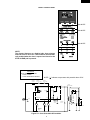
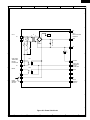
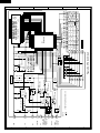
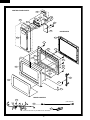
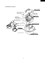
R-315EW
SUPPLEMENTAL SERVICE MANUAL
S6116R315EPW/
MICROWAVE OVEN
MODEL
R-315EW
In the interest of user-safety the oven should be restored to its original
condition and only parts identical to those specified should be used.
WARNING TO SERVICE PERSONNEL: Microwave ovens contain circuitry capable of producing very high voltage and
current, contact with following parts may result in a severe,
possibly fatal, electrical shock. (High Voltage Capacitor, High
Voltage Power Transformer, Magnetron, High Voltage Rectifier
Assembly, High Voltage Harness etc..)
This is a supplemental Service Manual for Model R-315EW. This model is quite similar to base
model R-310EW. Use this supplemental manual together with the Base Model Service Manual
(Refer No. is S2103R310EPW/) for complete operation, service information, etc..
TABLE OF CONTENTS
Page
PRECAUTIONS TO BE OBSERVED BEFORE AND DURING SERVICING TO
AVOID POSSIBLE EXPOSURE TO EXCESSIVE MICROWAVE ENERGY ................... INSIDE FRONT COVER
BEFORE SERVICING ...................................................................................................... INSIDE FRONT COVER
WARNING TO SERVICE PERSONNEL ................................................................................................................ 1
MICROWAVE MEASUREMENT PROCEDURE ................................................................................................... 2
FOREWORD AND WARNING ............................................................................................................................... 3
PRODUCT DESCRIPTION .................................................................................................................................... 4
PICTORIAL DIAGRAM .......................................................................................................................................... 6
POWER UNIT CIRCUIT ........................................................................................................................................ 7
CPU UNIT CIRCUIT .............................................................................................................................................. 8
PARTS LIST .......................................................................................................................................................... 9
PACKING AND ACCESSORIES ......................................................................................................................... 13
This document has been published to be used for after
sales service only.
The contents are subject to change without notice.
SHARP CORPORATION
15
R-315EW
PRECAUTIONS TO BE OBSERVED BEFORE AND
DURING SERVICING TO AVOID POSSIBLE
EXPOSURE TO EXCESSIVE MICROWAVE
ENERGY
(a) Do not operate or allow the oven to be operated with the door open.
(b) Make the following safety checks on all ovens to be serviced before activating the magnetron or other
microwave source, and make repairs as necessary: (1) interlock operation, (2) proper door closing, (3)
seal and sealing surfaces (arcing, wear, and other damage), (4) damage to or loosening of hinges and
latches, (5) evidence of dropping or abuse.
(c) Before turning on microwave power for any service test or inspection within the microwave generating
compartments, check the magnetron, wave guide or transmission line, and cavity for proper alignment,
integrity, and connections.
(d) Any defective or misadjusted components in the interlock, monitor, door seal, and microwave
generation and transmission systems shall be repaired, replaced, or adjusted by procedures described
in this manual before the oven is released to the owner.
(e) A microwave leakage check to verify compliance with the Federal Performance Standard should be
performed on each oven prior to release to the owner.
BEFORE SERVICING
Before servicing an operative unit, perform a microwave emission check as per the Microwave
Measurement Procedure outlined in this service manual.
If microwave emissions level is in excess of the specified limit, contact SHARP ELECTRONICS
CORPORATION immediately @1-800-237-4277.
If the unit operates with the door open, service person should 1) tell the user not to operate the oven
and 2) contact SHARP ELECTRONICS CORPORATION and The Food and Drug Administration's
Center for Devices and Radiological Health immediately.
Service personnel should inform SHARP ELECTRONICS CORPORATION of any certified unit
found with emissions in excess of 4mW/cm2. The owner of the unit should be instructed not to use
the unit until the oven has been brought into compliance.
16
R-315EW
WARNING TO SERVICE PERSONNEL
Microwave ovens contain circuitry capable of producing very high voltage and current, contact with
following parts may result in a severe, possibly
fatal, electrical shock.
(Example)
High Voltage Capacitor, High Voltage Power Transformer, Magnetron, High Voltage Rectifier Assembly, High Voltage Harness etc..
Read the Service Manual carefully and follow all
instructions.
Don't Touch !
Danger High Voltage
When the testing is completed,
1. Disconnect the power supply cord, and then remove
outer case.
2. Open the door and block it open.
3. Discharge high voltage capacitor.
4. Reconnect the leads to the primary of the power
transformer.
5. Reinstall the outer case (cabinet).
6. Reconnect the power supply cord after the outer case is
installed.
7. Run the oven and check all functions.
Before Servicing
1. Disconnect the power supply cord
outer case.
2. Open the door and block it open.
3. Discharge high voltage capacitor.
, and then remove
WARNING:RISK OF ELECTRIC SHOCK.
DISCHARGE THE HIGH-VOLTAGE
CAPACITOR BEFORE SERVICING.
After repairing
The high-voltage capacitor remains charged about 60
seconds after the oven has been switched off. Wait for 60
seconds and then short-circuit the connection of the highvoltage capacitor (that is the connecting lead of the highvoltage rectifier) against the chassis with the use of an
insulated screwdriver.
1. Reconnect all leads removed from components during
testing.
2. Reinstall the outer case (cabinet).
3. Reconnect the power supply cord after the outer case is
installed.
4. Run the oven and check all functions.
Whenever troubleshooting is performed the power supply
must be disconnected. It may, in some cases, be necessary
to connect the power supply after the outer case has been
removed, in this event,
1. Disconnect the power supply cord, and then remove
outer case.
2. Open the door and block it open.
3. Discharge high voltage capacitor.
4. Disconnect the leads to the primary of the power
transformer.
5. Ensure that the leads remain isolated from other
components and oven chassis by using insulation tape.
6. After that procedure, reconnect the power supply cord.
Microwave ovens should not be run empty. To test for the
presence of microwave energy within a cavity, place a cup
of cold water on the oven turntable, close the door and set
the power to HIGH and set the microwave timer for two (2)
minutes. When the two minutes has elapsed (timer at zero)
carefully check that the water is now hot. If the water
remains cold carry out Before Servicing procedure and reexamine the connections to the component being tested.
When all service work is completed and the oven is fully
assembled, the microwave power output should be checked
and a microwave leakage test should be carried out.
1
R-315EW
MICROWAVE MEASUREMENT PROCEDURE
A. Requirements:
1) Microwave leakage limit (Power density limit): The power density of microwave radiation emitted by a microwave oven
should not exceed 1mW/cm2 at any point 5cm or more from the external surface of the oven, measured prior to acquisition
by a purchaser, and thereafter (through the useful life of the oven), 5 mW/cm2 at any point 5cm or more from the external
surface of the oven.
2) Safety interlock switches Primary interlock relay and door sensing switch shall prevent microwave radiation emission in
excess of the requirement as above mentioned, secondary interlock switch shall prevent microwave radiation emission
in excess of 5 mW/cm2 at any point 5cm or more from the external surface of the oven.
B. Preparation for testing:
Before beginning the actual measurement of leakage, proceed as follows:
1) Make sure that the actual instrument is operating normally as specified in its instruction booklet.
Important:
Survey instruments that comply with the requirement for instrumentation as prescribed by the performance standard
for microwave ovens, 21 CFR 1030.10(c)(3)(i), must be used for testing.
2) Place the oven tray in the oven cavity.
3) Place the load of 275±15 ml (9.8 oz) of tap water initially at 20±5˚C (68˚F) in the center of the oven cavity.
The water container shall be a low form of 600 ml (20 oz) beaker with an inside diameter of approx. 8.5 cm (3-1/2 in.) and
made of an electrically nonconductive material such as glass or plastic.
The placing of this standard load in the oven is important not only to protect the oven, but also to insure that any leakage
is measured accurately.
4) Set the cooking control on Full Power Cooking Mode
5) Close the door and select a cook cycle of several minutes. If the water begins to boil before the survey is completed,
replace it with 275 ml of cool water.
C. Leakage test:
Closed-door leakage test (microwave measurement)
1) Grasp the probe of the survey instrument and hold it perpendicular to the gap between the door and the body of the oven.
2) Move the probe slowly, not faster than 1 in./sec. (2.5 cm/sec.) along the gap, watching for the maximum indication on the
meter.
3) Check for leakage at the door screen, sheet metal seams and other accessible positions where the continuity of the metal
has been breached (eg., around the switches, indicator, and vents).
While testing for leakage around the door pull the door away from the front of the oven as far as is permitted by the closed
latch assembly.
4) Measure carefully at the point of highest leakage and make sure that the highest leakage is no greater than 4mW/cm2.
NOTE: After servicing, record data on service invoice and microwave leakage report.
2
R-315EW
SERVICE MANUAL
MICROWAVE OVEN
R-315EW
FOREWORD
This Manual has been prepared to provide Sharp Electronics Corp. Service Personnel with Operation and Service
Information for the SHARP MICROWAVE OVEN, R-315EW.
The model R-315EW is quite similar to base model R-310EW (Refer No. is S2103R310EPW/).
It is recommended that service personnel carefully study the entire text of this manual and the base model's manual so that
they will be qualified to render satisfactory customer service.
Check the interlock switches and the door seal carefully. Special attention should be given to avoid electrical shock and
microwave radiation hazard.
WARNING
Never operate the oven until the following points are ensured.
(A) The door is tightly closed.
(B) The door brackets and hinges are not defective.
(C) The door packing is not damaged.
(D) The door is not deformed or warped.
(E) There is no other visible damage with the oven.
Servicing and repair work must be carried out only by trained service personnel.
DANGER
Certain initial parts are intentionally not grounded and present a risk of electrical shock only during servicing.
Service personnel - Do not contact the following parts while the appliance is energized;
High Voltage Capacitor, Power Transformer, Magnetron, High Voltage Rectifier Assembly, High Voltage
Harness;
If provided, Vent Hood, Fan assembly, Cooling Fan Motor.
All the parts marked “*” on parts list are used at voltages more than 250V.
Removal of the outer wrap gives access to voltage above 250V.
All the parts marked “∆” on parts list may cause undue microwave exposure, by themselves, or when they are damaged,
loosened or removed.
SHARP ELECTRONICS CORPORATION
SHARP PLAZA, MAHWAH,
NEW JERSEY 07430-2135
3
R-315EW
PRODUCT DESCRIPTION
SPECIFICATIONS
ITEM
DESCRIPTION
Power Requirements
120 Volts / 14.2 Amperes
60 Hertz
Single phase, 3 wire grounded
Power Output
1200 watts (IEC TEST PROCEDURE)
Operating frequency of 2450MHz
Case Dimensions
Width 20-1/2"
Height 11-7/8"
Depth 17-1/8"
Cooking Cavity Dimensions
Width 14-3/4"
Height 8-3/4"
Depth 15-3/4"
1.2 Cubic Feet
Control Complement
Touch Control System
Clock ( 1:00 - 12:59 )
Timer (0 - 99 min. 99 seconds)
Microwave Power for Variable Cooking
Repetition Rate;
P-HI .................................................. Full power throughout the cooking time
P-90 .................................................................... approx. 90% of Full Power
P-80 .................................................................... approx. 80% of Full Power
P-70 .................................................................... approx. 70% of Full Power
P-60 .................................................................... approx. 60% of Full Power
P-50 .................................................................... approx. 50% of Full Power
P-40 .................................................................... approx. 40% of Full Power
P-30 .................................................................... approx. 30% of Full Power
P-20 .................................................................... approx. 20% of Full Power
P-10 .................................................................... approx. 10% of Full Power
P-0 .................................................... No power throughout the cooking time
POPCORN pad, KEEP WARM pad, MINUTE PLUS pad
INSTANT ACTION pads, REHEAT CENTER pad
COMPU DEFROST pads, Number selection pads
POWER LEVEL pad, TIMER/CLOCK pad
STOP/CLEAR pad, START pad
Oven Cavity Light
Yes
Safety Standard
UL Listed
FCC Authorized
DHHS Rules, CFR, Title 21, Chapter 1, Subchapter J
4
R-315EW
TOUCH CONTROL PANEL
See NOTE.
See NOTE.
See NOTE.
NOTE:
The directed features are disabled after three minutes
when the oven is not in use. These features are automatically enabled when the door is opened and closed or the
STOP/ CLEAR pad is pressed.
SCHEMATIC
NOTE: CONDITION OF OVEN
1. DOOR CLOSED
2. CLOCK APPEARS ON DISPLAY
MONITOR
FUSE 20A
THERMAL
CUT-OUT (OVEN)
NOTE: " " indicates components with potential above 250V.
THERMAL
CUT-OUT (MG.)
N.O.
N.O.
A2
(RY-2)
(RY-1)
A1
POWER
TRANSFORMER
CONTROL UNIT
COM.
COM.
SH-B
GRN
120V AC
60 Hz
SH-A
DOOR
SENSING
SWITCH
TTM
OL
OVEN
LAMP
CAPACITOR 0.94µF
AC 2300V
PRIMARY
INTERLOCK
RELAY
MONITOR
SWITCH
FM
TURNTABLE
MOTOR
FAN
MOTOR
SECONDARY
INTERLOCK
SWITCH
Figure O-1. Oven Schematic-Off Condition
5
RECTIFIER
MAGNETRON
H
1
2
3
6
2
CN-A
RY2
4
YLW
BLK
RED
RED
CN-A
1 WHT
2
RED
N.C.
5
COM.
WHT
TURNTABLE
MOTOR
WHT
BLK
GRY
RED
GRY
BLK
POWER
TRANSFORMER
HIGH VOLTAGE
WIRE B
MAGNETRON
HIGH VOLTAGE
CAPACITOR
HIGH VOLTAGE COMPONENTS
BLK
THERMAL
CUT-OUT (MG)
5
Figure S-1. Pictorial Diagram
WHT
BLK
MONITOR
FUSE
&
HOLDER
BLK
FAN MOTOR
WHT
GRY
BLK
BLK
NOTE:
The neutral (WHT) wire must be
connected to the neutral (WHT)
wire of the power supply cord.
POWER SUPPLY
CORD 120V 60Hz
4
WHT
GRY
WHT
COM.
SECONDARY NO
INTERLOCK
SWITCH
MONITOR
SWITCH
RED
(To oven cavity front flange.)
E
(POWER UNIT)
1
T1
SH-B
PRIMARY
INTERLOCK
RELAY
CN-C
CN-C
GRN
THERMAL
CUT-OUT (OVEN)
BLK
WHT
N
3
BLK
RY1
SP1
SH-A
GRN
(CPU UNIT)
CN-G
IC1
GRN
GRN
RED
BLK
H
A
COM.
N.O.
WHT
BLK
2
YLW
YLW
G
CONTROL UNIT
F
DOOR
SENSING
SWITCH
D
OVEN LAMP
AND SOCKET
NOTE:
Hot (YLW) wire must be
connected to the terminal
with blue mark on the
oven light socket.
C
WHT
YLW
B
NOTE:
The grounding conductor of
the power supply cord has
been grounded by power
supply cord fixing screw.
The screw must allways be
kept tight.
1
H.V.
RECTIFIER
BLUE MARK
R-315EW
6
A
B
C
6
D
E
F
G
H
R-315EW
2
1
4
3
6
5
A
A
B
B
C9
T1
3
A2
C
d
a
4
10G471K
A1
VRS1
AC
CN-C
9PIN LEAD WIRE
HARNESS
GND
1
b
7
+
D1
S1NB10
–
C3
C1 1000µ/25v
CN-A
SP1
(J1)
VR
D
c
OVEN LAMP
TURNTABLE
MOTOR
FAN MOTOR
AC
RY1
COM
C4
BUZZER
NO
C6
OVEN LAMP
TURNTABLE
MOTOR
FAN MOTOR
NO
C8
MICRO
COM
C7
SH-A
C2
NC
SH-B
C1
DOOR
SENSING
SWITCH
E
RY2
MICRO
F
GND
C
C5
D
INT
DOOR
SENSING
SWITCH
E
F
G
G
H
H
Figure S-2. Power Unit Circuit
1
2
4
3
7
5
6
C-2
C-4
C-9
C-5
DOOR
SENSING
SWITCH
MICRO
R4 560 1/2w
–
+
Q22
DTA123JKA
Q21
DTD143EKA
: IF NOT SPECIFIED 1/10W ± 5%
D40
MA152WA
D20
MA152WA
NOTE
C-1
C-8
C-7
OVEN LAMP
TURNTABLE
C-6
MOTOR
FAN MOTOR
NC
BUZZER
INT
VR
C21
R41 15k
Q20
DTA143EKA
C20 0.1µ/50v
Q30
DTA143EKA
Q10
DTA143EKA
–
5
R73 15k
R72 15k
R71 15k
R70 15k
C60-65 330pF/50v
80
25
25
SEG 1
SEG 2
8
9
KEY UNIT
KEEP WARM
RICE
3
4
STOP
CLEAR
Figure S-3. CPU Unit Circuit
SEG 3
G6
G12
G14
SEG 5
G7
FROZEN POWER
ENTREES LEVEL
0
G10
G13
COOK
SEG 4
IC1
IXA096DR
G11
5
R9 4.7k R8 4.7k R7 4.7k
G9
G8
R90 15k
24
VL2
VL1
AN7
AN6
AN5
AN4
P63
AN2
AN1
AN0
P57
P56
P55
CNTR0
P53
P52
P51
P50
P47
P46
P45
P44
P43
INT0
1
GND
DEFROST
SEG 8
SEG 9
64
SEG10
41
SEG11
BAKED
POTATOES
POPCORN
7
2
G5
40
SEG8
SEG9
SEG10
SEG11
SEG12
SEG13
SEG14
SEG15
SEG16
SEG17
SEG18
SEG19
SEG20
SEG21
P06
P07
P10
P11
P12
P13
P14
P15
P16
P17
65
NO.
LBS.
CUPS
OZ.
AUTO
SEG18
SEG16
SEG15
SEG14
CHICKEN
PIECES
G1
R60
15k
COM2
TIMER
CLOCK
REHEAT <DEF>
CENTER GROUND
MEAT
GROUND
FROZEN
MEAT
VEGETABLES
6
START
FRESH
STEAKS
VEGETABLES CHOPS
1
G2
G3
SEG13
MINUTE
PLUS
SEG17
G4
1
4
R69 15k
R68 15k
(J17) 4.7k
CF1 CST4.00MGW
(J15) 4.7k
(J16) 47k
(J13) 4.7k
(J11) 4.7k
(J14)
(J12)
(J10)
Q2
2SA1037AK
C4
0.01µ/25v
R6 15k
+
SEG12
SEG 6
R1 82
C10
0.1µ
/50v
10µ
/35v
C1 0.1µ/50v
R30 3.3k
R2 4.7k
Q1
2SA1037AK
R40
LD1 LD2 LD3 LD4
4.7k
C2 220µ/10v
R10 15k
C40
0.01µ
/25v
C3 0.01µ/25v
C11 0.01µ/25v
R79 270k
R5 1k
ZD1
UDZ4.3B
R78 270k
R77 270k
R76 270k
R75 270k
R74 270k
SEG 7
VL3
COM0
COM1
COM2
COM3
AVSS
VREF
VCC
SEG0
SEG1
SEG2
SEG3
SEG4
SEG5
SEG6
SEG7
R12 4.7k
R80
8
1M
4
R67
15k
3
R66
15k
2
3
R65
15k
H
P41
P40
RESET
P71
P70
XIN
XOUT
VSS
P27
P26
P25
P24
P23
P22
P21
P20
D
R63
15k
C-3
SEG19
GND
SEG20
G
COM3
F
SEG21
1
2
R64
15k
1
C65
C64
C63
C62
C61
C60
LIQUID CRYSTAL DISPLAY
COM1
E
SEG22
C
R62
15k
A
R61
15k
B
CPU UNIT
R-315EW
5
6
A
B
C
6
D
E
F
G
H
R-315EW
PARTS LIST
Note: The parts marked “∆” may cause undue microwave exposure.
The parts marked “*” are used in voltage more than 250V.
REF. NO.
PART NO.
DESCRIPTION
1- 1
1- 1
1- 2
1- 3
1- 3
1- 4
1- 4
1- 5
1- 5
1- 6
1- 7
1- 7
1- 8
1- 8
1- 9
1-10
1-11
1-11
1-12
1-12
1-13
1-13
1-14
QSW-MA147WRZZ
QSW-MA137WRE0
QFSHDA009WRE0
FFS-BA021WRK0
FFS-BA023WRK0
RTHM-A116WRE0
RTHM-A078WRE0
FACCDA085WREZ
FACCDA083WRE0
FH-DZA088WRK0
RC-QZA287WRZZ
RC-QZA268WRZZ
RV-MZA291WRE0
RV-MZA295WRE0
RMOTEA383WRE0
QSOCLA021WRE0
RLMPTA081WRZZ
RLMPTA068WRE0
RMOTDA186WRE0
RMOTDA211WRE0
RTHM-A120WRE0
RTHM-A080WRE0
RTRN-A635WRZZ
2nd interlock switch/door sensing switch
2nd interlock switch/door sensing switch (Interchangeable)
Fuse holder
Monitor fuse 20A and monitor switch (V-16G-2C25) assembly
"
" (AM51620C53Y1) assembly (Interchangeable)
Thermal cut-out 125 deg.
Thermal cut-out 125 deg. (Interchangeable)
Power supply cord
Power supply cord (Interchangeable)
High voltage rectifier assembly
High voltage capacitor
High voltage capacitor (Interchangeable)
Magnetron
Magnetron (Interchangeable)
Fan motor
Oven lamp socket
Oven lamp
Oven lamp (Interchangeable)
Turntable motor
Turntable motor (Interchangeable)
Thermal cut-out 145 deg.C
Thermal cut-out 145 deg.C(Interchangeable)
Power transformer
2222-
GCABUA821WRPZ
GDAI-A316WRW0
GLEGPA074WRE0
GLEGPA077WRF0
Outer case cabinet
Bottom plate
Foot
Leg
Q'TY
CODE
2
2
1
1
1
1
1
1
1
1
1
1
1
1
1
1
1
1
1
1
1
1
1
AG
AH
AH
AL
AS
AK
AL
AQ
AQ
AP
AU
AS
BH
BF
AV
AH
AK
AG
AW
AS
AH
AP
BQ
1
1
2
1
AX
AC
AH
1
1
1
1
1
1
1
1
1
1
1
1
1
1
1
1
1
4
BA
AC
AW
AD
AF
AE
AG
AN
AN
AG
AP
AE
BN
BA
AW
AE
AF
AA
1
1
1
1
1
1
1
1
1
1
1
1
1
1
2
1
1
AU
AF
AH
AD
AL
AT
-AU
AC
AF
AF
AE
AC
AE
AG
AD
AB
ELECTRIC PARTS
*
*
*
*∆
*∆
*
CABINET PARTS
1
2
3
4
CONTROL PANEL PARTS
3- 1
3- 1A
3- 1B
3- 1C
3- 1D
C1
D1
RY1
RY2
SP1
T1
VRS1
3- 2
3- 3
3- 3-1
3- 4
3- 5
3- 6
DPWBFC021WRKZ
QCNCMA446DRE0
FW-VZA250DRE0
FW-VZA195DRE0
FW-VZA256DREZ
VCEAB31EW108M
RSRCDA013DRE0
RRLY-A094DRE0
RRLY-A114DRE0
RALM-A014DRE0
RTRNPA110DRE0
RH-VZA032DRE0
DPWBFC163WRKZ
FPNLCB583WRKZ
FUNTKB079WREZ
PSHEPA588WRE0
LHLD-A205WRF0
XEPSD30P08XS0
Power unit
2-pin connector (CN-A)
9pin wire harness (CN-C)
Switch harness A (SH-A)
Switch harness B (SH-B)
Capacitor
1000 uF 25V
Diode bridge (S1NB10)
Relay (OMIF-S-112LM)
Relay (DU12D1-1P(M)-R)
Buzzer (PKM22EPT)
Transformer
Varistor (10G471K)
CPU unit
Control panel frame with key unit
Key unit
LED sheet
LCD holder
Screw; 3mm x 8mm
4- 1
4- 2
4- 3
4- 4
4- 5
4- 6
4- 7
4- 8
4- 9
4-10
4-11
4-12
4-13
4-14
4-15
4-16
4-17
PDUC-A724WRF0
PPACGA084WRF0
PHOK-A116WRFZ
LBNDKA099WRW0
NFANJA029WRE0
PDUC-A728WRW0
*************
LANGFA194WRW0
PCUSGA551WREZ
LANG-A079WRWZ
LANG-A078WRWZ
NCPL-A053WRFZ
PCUSUA511WRP0
PCOVPA349WRE0
PCUSGA339WRP0
PCUSGA533WRP0
PCUSUA512WRP0
Air separater
TTM packing
Latch hook
Capacitor holder
Fan blade
Fan duct
Oven cavity (Not a replaceable part)
Chassis support
Cushion
Air guide
Barrier
Coupling
Cushion
Waveguide cover
Cushion
Cushion
Cushion
OVEN PARTS
∆
∆
9
R-315EW
REF. NO.
4-18
4-19
4-20
4-21
4-22
4-22
PART NO.
PCUSGA529WRP0
PCUSUA186WRP0
PCUSUA157WRP0
PCUSUA212WRP0
PCUSUA474WRP0
PCUSUA576WRPZ
DESCRIPTION
Cushion
Cushion
Cushion
Cushion
Cushion
Cushion
Q'TY
1
1
1
2
2
1
CODE
AC
AC
AC
AB
AC
AE
1
1
1
1
1
1
6
1
2
2
1
BD
AH
AZ
AS
AE
AC
AA
AB
AC
AB
AG
1
1
1
1
1
1
1
1
AQ
AR
AU
AF
AB
AC
AC
AN
5
1
4
1
3
17
1
2
2
4
AA
AA
AA
AA
AA
AA
AA
AC
AA
AA
DOOR PARTS
∆
∆
∆
5- 1
5- 2
5- 3
5- 4
5- 5
5- 6
5- 7
5- 8
5- 9
5-10
5-11
FDORFA332WRT0
PSHEPA382WRE0
GWAKPA790WRRZ
HPNL-A742WRRZ
LSTPPA193WRFZ
MSPRTA187WRE0
XEPSD40P08000
PCUSUA461WRP0
PCUSUA553WRPZ
PCUSUA554WRPZ
GCOVHA417WRFZ
Door panel
Sealer film
Door frame
Door screen
Latch head
Latch spring
Screw : 4mm x 8mm
Cushion
Cushion
Cushion
Choke cover
66666666-
1
2
3
4
5
6
7
8
FROLPA079WRK0
NTNT-A079WRF0
FW-VZB787WREZ
QW-QZA242WRZZ
PZET-A012WRE0
TCAUAA265WRRZ
TCAUAA254WRR0
TINSEA908WRRZ
Turntable support
Turntable tray
Main wire harness
High voltage wire B
Terminal insulator
DHHS caution label
Monitor caution label
Instruction book
7- 1
7- 2
7- 3
7- 4
7- 5
7- 6
7- 7
7- 8
7- 9
7-10
XHPSD40P08K00
XHPSD30P06000
XHTSD40P08RV0
XHTSD40P12RV0
XOTSD40P12RV0
XOTSD40P12000
XOTSE40P08000
LX-CZA070WRE0
LX-CZ0052WRE0
XHPSD40P08000
Screw :
Screw :
Screw :
Screw :
Screw :
Screw :
Screw :
Special
Special
Screw :
MISCELLANEOUS
*
SCREWS,NUTS AND WASHERS
4mm x
3mm x
4mm x
4mm x
4mm x
4mm x
4mm x
screw
screw
4mm x
8mm
6mm
8mm
12mm
12mm
12mm
8mm
(Torx tamper proof screw)
8mm
HOW TO ORDER REPLACEMENT PARTS
To have your order filled promptly and correctly, please furnish the following information.
1. MODEL NUMBER
2. REF. NO.
3. PART NO.
4. DESCRIPTION
Order Parts from the authorized SHARP parts Distributor for your area.
Defective parts requiring return should be returned as indicated in the Service Policy.
10
R-315EW
2
1
4
3
7-5
2-1
OVEN AND CABINET PARTS
6
5
7-8
A
A
7-5
4-22
7-10
1-10
B
7-8
1-11
B
4-17
4-20
1-8
1-4
C
7-7
6-7
7-6
6-6
4-13
C
4-11
7-6
4-7
4-10
4-21
7-3
D
D
1-5
7-6
7-4
4-19
4-22
7-1
4-12
1-7
4-21
1-6
4-15
E
7-9
7-6
7-2
1-1
E
1-13
4-14
6-2
4-4
4-23
4-2
4-18
1-2
1-3
1-12
F
4-5
1-14
6-1
4-8
7-6
4-3
7-6
7-3
1-1
F
7-1
7-5
7-1
4-16
4-1
4-9
2-2
4-15
4-6
2-4
G
1-9
G
7-6
2-3
7-6
H
H
7-6
7-6
7-6
2-3
1
2
4
3
11
5
6
R-315EW
2
1
4
3
CONTROL PANEL PARTS
6
5
3-2
A
A
3-6
3-5
3-3
3-4
3-6
B
B
3-1
DOOR PARTS
5-11
3-3-1
C
C
5-7
5-2
5-7
D
D
5-1
5-10
5-9
5-7
5-7
5-3
E
E
5-7
5-10
5-9
5-5
5-4
F
F
5-6
5-8
G
G
MISCELLANEOUS
6-3
(CAPACITOR)
6-4
H
H
6-5
Actual wire harness may be different from illustration.
1
2
4
3
12
5
6
R-315EW
PACKING AND ACCESSORIES
TOP PAD ASSEMBLY
FPADBA458WRKZ
DOOR PROTECTION SHEET
CABINET COVER
SPADPA204WRE0
SPAKHA011WRE0
PLASTIC BAG
SSAKHA034WRE0
FOAM SHEET
SPAKHA012WREZ
(only for R-310EK)
6- 8
INSTRUCTION BOOK
& PRINTING MATTER
6- 2
TURNTABLE TRAY
BOTTOM PAD ASSEMBLY
FPADBA417WRKZ
6- 1 TURNTABLE SUPPORT
TRAY PACK
INTO THE
OVEN CAVITY
SPADFA451WRE0
Not replaceable items.
PACKING CASE
SPAKCD615WRZZ
13
R-315EW
COPYRIGHT © 2001 BY SHARP CORPORATION
ALL RIGHTS RESERVED.
No part of this publication may be reproduced,
stored in retrieval systems, or transmitted in any
form or by any means, electronic, mechanical, photocopying, recording, or otherwise, without prior
written permission of the publisher.
2001 SHARP CORP. (6S1.700E) Printed in U.S.A
14