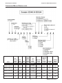
1
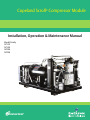
Copeland Scroll® Compressor Module
Installation, Operation & Maintenance Manual
Model Family
SZV32
SZV44
SZO44
SZO56
Dual-Compressor Module
TABLE OF CONTENTS
TABLE OF CONTENTS
Compressor Module Nomenclature. ............................................................................................ iv
Important Safety Information........................................................................................................1
1.0Introduction.......................................................................................................................3
1.1
The Compressor Module............................................................................................................... 3
1.2
The Compressor............................................................................................................................ 4
1.3
The Compressor Package............................................................................................................. 4
2.0Installation........................................................................................................................5
2.1
Installation Guidelines.................................................................................................................... 5
2.1.1 Required Component—Inlet Gas Scrubber......................................................................................5
2.1.2 General Installation Guidelines.........................................................................................................5
2.2
Inlet and Discharge Pressures....................................................................................................... 5
2.3
Ambient Temperature Range......................................................................................................... 6
2.4
Installation Clearance and Dimensions......................................................................................... 7
2.5
Process and Instrumentation Diagrams (P&IDs)........................................................................... 8
2.6
Electrical Controls.......................................................................................................................... 9
2.6.1 General Considerations....................................................................................................................9
2.6.2 Oil Cooler Fan Control....................................................................................................................10
2.6.3 Compressor Module Motor Protection............................................................................................12
2.6.4 Electrical Requirements..................................................................................................................13
2.6.5 Wiring.............................................................................................................................................14
2.6.6 Variable Frequency Drive (VFD) Terminations...............................................................................15
3.0Operation.........................................................................................................................17
3.1
Initial Startup - Compressor Module............................................................................................ 17
3.1.1 Pre-Startup Checklist......................................................................................................................17
3.1.2 Post-Startup Checklist....................................................................................................................17
3.2
Initial Startup - Compressor Package.......................................................................................... 18
3.3
Normal Operation Checklist......................................................................................................... 18
4.0Maintenance.....................................................................................................................19
4.1
Routine Maintenance................................................................................................................... 19
i
2006SSD-75 R4 (10/10)
Dual-Compressor Module
TABLE OF CONTENTS
4.2
Maintenance Tools....................................................................................................................... 20
4.3
Checking the Oil Level................................................................................................................. 21
4.3.1 Oil Level Guidelines - Minimum Speed..........................................................................................21
4.3.2 Oil Level Guidelines - Maximum Speed.........................................................................................21
4.4
Oil Capacity and Type.................................................................................................................. 21
4.5
Adding and Removing Oil............................................................................................................ 22
4.5.1 Topping Off the Oil Level................................................................................................................22
4.5.2 Changing the Oil.............................................................................................................................23
4.6
Cleaning the Inlet Screen............................................................................................................ 25
4.7
Servicing the Scavenge Line Orifice............................................................................................ 25
4.8
Changing the Second-Stage Separator Element........................................................................ 26
4.9
Changing the Oil Filter Element................................................................................................... 26
5.0Troubleshooting..............................................................................................................27
5.1
Troubleshooting Guide................................................................................................................ 27
5.2
Motor Winding Resistance........................................................................................................... 27
5.3
Platform Symptoms Diagnosis..................................................................................................... 28
6.0Specifications...................................................................................................................29
Appendix A  Material Data Safety Sheet....................................................................................32
A.1
Supplier........................................................................................................................................ 32
A.2
Product Name and Information.................................................................................................... 32
A.3
Components and Hazard Statement........................................................................................... 32
A.4
Safe Handling and Storage......................................................................................................... 32
A.5
Physical Data............................................................................................................................... 32
A.6
Fire and Explosion Hazards......................................................................................................... 33
A.7
Reactivity Data............................................................................................................................. 33
A.8
Health Hazard Data..................................................................................................................... 33
A.9
Personal Protection Information.................................................................................................. 33
A.10 Spill or Leak Procedures.............................................................................................................. 33
A.11 Waste Disposal Methods............................................................................................................. 33
ii
2006SSD-75 R4 (10/10)
Dual-Compressor Module
TABLE OF CONTENTS
FIGURES
Figure 1
Compressor Module Components .........................................................................................................3
Figure 2
Copeland Scroll® Compressor Cross Section.........................................................................................4
Figure 3
Typical Compressor Package ................................................................................................................4
Figure 4
Compressor Module Dimensions, in. (mm).............................................................................................7
Figure 5
Compressor Module Gas and Oil Flow Diagram and Safety Shutdowns............................................... 8
Figure 6
Brushless DC Fan ................................................................................................................................10
Figure 7
Basic Fan Control System ...................................................................................................................10
Figure 8
Optional Customer-Installed High Temperature Fan Control System .................................................. 11
Figure 9
Oil Cooling and Thermal Valve.............................................................................................................. 11
Figure 10 Motor Control .......................................................................................................................................12
Figure 11 Typical Compressor Module Electrical Requirements..........................................................................13
Figure 12 Control Circuit Terminations .................................................................................................................14
Figure 13 Power Terminations ..............................................................................................................................14
Figure 14 Maintenance Tools................................................................................................................................18
Figure 15 Adding or Draining Oil ..........................................................................................................................21
Figure 16 Gas Inlet Block and Screen .................................................................................................................23
Figure 17 Scavenge Line Orifice ..........................................................................................................................23
Figure 18 Oil Filter Bowl and Element...................................................................................................................24
TABLES
Table 1
Inlet and discharge pressure limits.........................................................................................................5
Table 2
Typical Compressor Module power supply requirements..................................................................... 13
Table 3
Maintenance summary..........................................................................................................................17
Table 4
Troubleshooting....................................................................................................................................25
Table 5
Motor winding resistance......................................................................................................................25
Table 6
Platform troubleshooting guidelines......................................................................................................26
Table 7
Compressor Module specifications.......................................................................................................27
Table 8
Compressor Module flow, pressure and horsepower data (see Notes 1 - 3*)...................................... 29
iii
2006SSD-75 R4 (10/10)

Dual-Compressor Module
Compressor Module Nomenclature
Compressor Module Nomenclature

Model
Max
Delivery
Pressure
(PSIG)
Max
Flow
(MCFD)
Drive
HP
High
Press
Switch
Setting
(PSIG)
Low
Press
Switch
Setting
High Temp
Setting
°F (°C)
Oil
Thermal
Bypass
Valve
Setpoint
°F (°C)
Gas Bypass
Valve
Module
Weight
(Lbs.)
Dual Scroll Units
SZO56C1A-EDE-110
150
260
30
215
0.75 PSIG
(52 mbarg)
240 (116)
200
NO
625
SZO44C1A-EDE-140
190
200
30
215
0.75 PSIG
(52 mbarg)
240 (116)
200
NO
625
SZO44C1A-EDE-244
190
200
30
215
0.75 PSIG
(52 mbarg)
240 (116)
200
YES
625
SZV44C1A-EDE-140
190
200
30
215
0.75 PSIG
(52 mbarg)
280 (138)
250
NO
625
SZV32C1A-EDE-150
275
150
30
290
0.75 PSIG
(52 mbarg)
280 (138)
250
NO
625
iv
2006SSD-75 R4 (10/10)
Dual-Compressor Module
Important Safety Information
Important Safety Information
This manual contains important instructions for installation, operation and maintenance of your Copeland
Scroll® Compressor Module.
WARNING
The Compressor Module must be installed ONLY in systems that have been designed by
qualified engineering personnel. The system must conform to all applicable local and national
regulations and safety standards.
These instructions are intended to assist in the installation and operation of the Compressor
Module and MUST be kept with the Compressor.
Service and maintenance of the Compressor Module must be performed by qualified technicians
only. Service and maintenance must conform to all applicable local and national regulations and
safety standards.
Thoroughly review this manual, all instructions and hazard warnings before performing any work
on the Compressor Module.
Maintain all Compressor Module operation and hazard warning labels.
WARNING
Flammable gas can form explosive mixtures with air. Explosive gases can cause property
damage, serious personal injury or death.
WARNING
Failure to disconnect and lockout electrical power from the Compressor Module before attempting
maintenance can cause shock, burns, severe personal injury or death.
WARNING
Loosening or removing pressure-containing components from the Compressor Module when it is
in operation can cause major property damage, serious personal injury or death.
Failure to relieve system pressure prior to performing service or maintenance on the Compressor
Module can cause property damage or serious personal injury.
CAUTION
Extreme heat can cause personal injury or property damage.
CAUTION
Always use a lifting device capable of supporting the full weight of the Compressor Module or
component being lifted.
Handling or lifting heavy assemblies can cause personal injury or property damage.
1
2006SSD-75 R4 (10/10)
Dual-Compressor Module
Important Safety Information
Safety Symbols Used in This Manual
SAFETY ALERT SYMBOL
When you see this symbol on the Compressor Module or in this manual, look for one of the
following words and be aware of the potential for personal injury or property damage.
WARNING
A Warning describes hazards that CAN or WILL cause serious personal injury, death or major
property damage.
CAUTION
A Caution describes hazards that CAN cause personal injury or property damage.
NOTE
A Note indicates special instructions that are very important and must be followed.
2
Form No. 2006SSD-75 (5/06) Rev. 0
Dual-Compressor Module
Introduction
1.0Introduction
The Copeland Scroll® SZO44 Compressor Module comes equipped with two Copeland Scroll®
Compressors designed for Class I, Division II applications. The Compressor Module is designed for
assembly into a Compressor Package ready for service in the field; the completed housing is done by
equipment Packagers. This section provides an overview of these components.
These terms are used throughout this manual:
• Compressor Module - the SZO44 Compressor Module shown in Section 1.1
• Compressor - a Copeland Scroll® Compressor (two per Compressor Module)
• Compressor Package - the entire assembly, including the Compressor Module, ready for service in
the field
• Packagers - the company that prepares the Compressor Module for service
• VFD - Variable Frequency Drive used to power a variable speed Compressor Module
1.1
The Compressor Module
The Compressor Module consists of two Compressors and the other components shown in Figure 1.
Figure 1Compressor Module Components
Inlet check valves (2)
Inlet suction screen
Oil coolers with fans (2)
LEFT
SIDE
VIEW
High discharge
gas pressure switch
High discharge
gas temp switch
Oil circuit
filter
Oil circuit
thermal
bypass valve
Copeland Scroll®
compressors (2) for
Class I, Divison II
RIGHT
SIDE
VIEW
Fan speed
thermistor
First-stage
oil separator
Oil level
sight tube
Oil cooler
fans (2)
Suction gas connection
(1-1/2" NPT)
Control wiring
terminations
Power wiring
terminations
Second-stage
separator
Discharge gas
connection (1" NPT)
3
2006SSD-75 R4 (10/10)
Dual-Compressor Module
1.2
Introduction
The Compressor
The Compressor refers to the Copeland Scroll® Compressor. Each Compressor Module has two
Compressors. Figure 2 shows a cross-section of a Compressor and its key components.
Figure 2 Copeland Scroll® Compressor Cross Section
1.3
The Compressor Package
The Compressor Package consists of the Compressor Module housed in an assembly ready for service
in the field. Equipment Packagers customize the assembly and complete the fabrication for Compressor
Modules for each application. Figure 3 shows a simplified example of a Compressor Package.
Figure 3 Typical Compressor Package
Inlet gas scrubber
for liquid removal
Control and
power panel
Gas aftercooler
(if applicable)
Oil
cooler
Compressor
Module
4
Form No. 2006SSD-75 (5/06) Rev. 0
Dual-Compressor Module
Installation
2.0Installation
2.1
Installation Guidelines
2.1.1 Required Component—Inlet Gas Scrubber
An appropriate inlet gas scrubber is REQUIRED to remove liquids from the gas prior to compression. If
there is potential for liquid slugging, a suitable trap must be installed to prevent liquid from flooding and
damaging the Compressor.
NOTE
Failing to use an appropriate inlet gas scrubber to remove liquids from the gas prior to
compression can cause flooding and damage the Compressor.
2.1.2 General Installation Guidelines
Follow these general guidelines for installation:
• The Compressor Module must be installed and operated in compliance with all applicable codes and
regulations.
• The system must be installed on a level surface.
• Install pipe unions or flanges to connect the system to the inlet and discharge piping for ease of
service.
• Install isolation valves on the inlet and discharge piping.
• A common ground must be connected between the Compressor Module and the
Compressor Package chassis. This ground must comply with the National Electric Code (NEC) and
any other applicable codes.
• Solid debris also must be removed from the gas prior to compression. When required, use a 5 to 10micron inlet filter to remove debris from the gas stream. The degree of filtration required depends on
the specific application.
2.2
Inlet and Discharge Pressures
Refer to Table 1 for acceptable inlet and discharge pressure levels.
Table 1
Type
Level
Minimum Inlet
Pressure
0.75 psig
Maximum Inlet
Pressure
25 psig
Discharge
Pressure
Range
Inlet and discharge pressure limits
70 psig
to
190 psig
(depends
on model)
Operating Guidelines
Consult the factory for operations below 0.75 psig.
Operation at pressures above 25 psig will result in:
• Excessive oil carryover
• Loss of oil from the Compressor Module
When the discharge pressure of the Compressor Module reaches the maximum,
which ranges from 70 to 190 psig, depending on the model (see Compressor
Module Nomenclature on page iv):
• The Compressor Module goes into high discharge pressure recycle if
equipped.
• The Compressor Module’s bypass regulator diverts gas from the high-pressure
side to the low-pressure side of the module.
All Compressor Modules must be equipped with pressure-limiting or relief
devices. A minimum pressure differential of 70 psi between inlet and discharge
pressure is required for proper operation.
5
2006SSD-75 R4 (10/10)
Dual-Compressor Module
Installation
NOTE: Required Component – High Pressure Discharge Gas Bypass Valve
In response to customer requests to eliminate redundancy, the high pressure discharge gas bypass (recycle)
valve was removed from some of the scroll modules (see table below).
Model
Max
Delivery
Pressure
PSIG
(barg)
Max
Flow
MCFD
(MCMD)
Drive
HP
High
Press
Switch
Setting
PSIG
(barg)
Low
Press
Switch
Setting
High Temp
Setting
°F (°C)
Oil
Thermal
Bypass
Valve
Setpoint
°F (°C)
Gas Bypass
Valve
Module
Weight
Lbs.
(kg)
Dual Scroll Units
SZO56C1A-EDE-110
150
(10.3)
260
(7.36)
30
215
(14.8)
0.75 PSIG
(52 mbarg)
240
(116)
200
(93)
NO
600
(272)
SZO44C1A-EDE-140
190
(13.1)
200
(5.7)
30
215
(14.8)
0.75 PSIG
(52 mbarg)
240
(116)
200
(93)
NO
600
(272)
SZO44C1A-EDE-244
190
(13.1)
200
(5.7)
30
215
(14.8)
0.75 PSIG
(52 mbarg)
240
(116)
200
(93)
YES
625
(283)
SZV44C1A-EDE-140
190
(13.1)
200
(5.7)
30
215
(14.8)
0.75 PSIG
(52 mbarg)
280
(138)
250
(121)
NO
625
(283)
SZV32C1A-EDE-150
275
(19.0)
150
(4.2)
30
290
(20.0)
0.75 PSIG
(52 mbarg)
280
(138)
250
(121)
NO
600
(272)
There are several reasons for making this change:
•
Locating the valve at the module level becomes redundant when two or more of our modules are
packaged together.
•
The original intent of the valve was to provide a means for the module to operate in cases where the
discharge was 100% blocked due to a downstream event; however, packagers are ultimately responsible
for high pressure relief.
•
When in use, the valve can act as an expansion valve when gas is passing through it, possibly
condensing water and or hydrocarbons which could be detrimental to our modules.
•
The valve is a back pressure regulator which can maintain a steady discharge pressure, however the
majority of packages with our modules are controlled through suction gas recycle. Also, most packages
have a back pressure regulator on the discharge of our modules to control the actual discharge pressure
to a minimum of 70 PSIG.
•
The presence of the valve was thought to protect the end user in case the discharge of our module is
isolated from the skid-level pressure relief valve and the other safeties on our module (high pressure
switch, drive current limit) are disabled or modified. However, inspectors do not consider our gas bypass
valve to be a high pressure safety device. It is the packager’s responsibility to provide adequate high
pressure safety relief/shutdown.
Packagers will need to install downstream pressure relief of our module.
2.3
Ambient Temperature Range
The Compressor Module operating ambient temperature is 20°F to +122°F (-29° to +50°C). For details on
ambient temperatures for VFD startup and Compressor Module operation, see Table 7 on page 27.
6
2006SSD-75 R4 (10/10)
Dual-Compressor Module
2.4
Installation
Installation Clearance and Dimensions
Allow sufficient clearance on all sides for service access, especially for gas and electrical connections at
the rear of the Compressor Module. Check applicable national and local electrical codes.
Cooling air flow is back to front—from the gas connection end to the oil cooler end. Do not block or restrict
the cooler fans or oil cooler.
Refer to Figure 4 for the dimensions of the Compressor Module.
Figure 4 Compressor Module Dimensions, in. (mm)
TOP
VIEW
FRONT
VIEW
SIDE
VIEW
BOTTOM
VIEW
7
2006SSD-75 R4 (10/10)
Dual-Compressor Module
2.5
Installation
Process and Instrumentation Diagrams (P&IDs)
Figure 5 Compressor Module Gas and Oil Flow Diagram and Safety Shutdowns
PSLL
001
Gas Discharge
1" -NPT
BPV-01
PS
001
PI
002
Gas Suction
1-1/2" -NPT
C-01
PS
002
PSHH
002
TS
002
TSHH
002
TE
002
PI
003
SEP-02
480V
J.B.
SEP-01
C-02
FL-05
EX-04
TCV-03
Module Limits
Code
BPV-01
C-01 / C-02
EX-04
FL-05
PI002
PI003
PS002 / PSHH002
PS001 / PSLL001
SEP-01
SEP-02
TCV-03
TE002
TS002 / TSHH002
Description
Gas bypass valve (optional)
Compressor and motor
Oil cooler, fan controlled by thermistor
Oil filter
Pressure gauge on first-stage oil separator
Pressure gauge on second-stage oil separator
High discharge gas pressure switch
Inlet low pressure switch
First-stage oil separator, 6” O.D.
Second-stage oil separator/coalescing element
Thermal bypass valve, 3-way, set @ 200°F (93°C)
Fan speed thermistor
High discharge gas temp switch
8
2006SSD-75 R4 (10/10)
Dual-Compressor Module
2.6
Installation
Electrical Controls
2.6.1 General Considerations
All shutdown devices are dry contact switches rated Class I, Division II that are wired to a terminal box
for connection to the packager supplied control circuit. The common wires on all switches are connected
together. All switches are closed unless a fault condition is detected.
All safety and protective devices must be installed and used in accordance with applicable codes and
regulations.
Switches
All switch connections are wired to terminal strips in a junction box on the Compressor Module.
Switch
• Low Inlet Gas Pressure
• High Discharge Gas Pressure
• High Temperature
Status
Normally Open, closes on pressure rise
Normally Closed, opens on pressure rise
Normally Closed, opens on temperature rise
Electrical Considerations - Variable Speed Compressor Module
• The Compressor power for a variable speed Compressor Module is the Variable Frequency Drive
(VFD).
• Compressor speed control can be either a 4-20 mA or 0-10V signal (transducer supplied by customer)
applied to the VFD. Speed can also be manually controlled with a potentiometer or the VFD can be
set for a fixed speed.
• Each Compressor on a module must be protected by an individual manual reset overload between
the VFD and the Compressor.
• The overloads should be able to be set at a maximum of 26A.
• If either overload opens, the VFD must be disabled.
• The overloads must be configured for manual reset.
• Normal full load run current for each Compressor on the module at 4800 rpm (80 Hz) is approximately
23A.
• The customer control circuit must supply an Enable signal to the VFD before the drive will accept a
Run Fwd signal.
• The VFD will start when the Enable signal is on and a Run Fwd signal is applied.
• The VFD will stop if the Run Fwd signal is off or the Enable signal is removed.
NOTE
The drive provides 24V for the Enable and Run Fwd signals.
The installer must connect the Enable and Run Forward terminals to the drive’s 24V terminal.
9
2006SSD-75 R4 (10/10)
Dual-Compressor Module
Installation
2.6.2 Oil Cooler Fan Control
The Compressor Module temperature is controlled by managing module oil flow and temperature. The
module’s precise temperature control is critical to system performance and equipment life. Maintaining
proper temperature control also reduces the possibility of gas condensing into liquids during operation.
• Cooling fans require 24VDC, 4.5A (105 Watts) x 2 (9A 210W total) for the Compressor Module. Fan
speed is controlled by a 0-10VDC control signal that is applied to the yellow lead on the fan terminal
strip. Standard Compressor Modules use a nonlinear PTC thermistor to monitor oil temperature and
provide a speed signal.
• High temperature Compressor Modules use a linear NTC thermistor to monitor oil temperature. This
signal is available to support a customer-provided fan speed control circuit.
• All power connections are wired to terminal strips in a junction box on the Compressor Module.
Figure 6 Brushless DC Fan
+24VDC
DC common
No connection feedback
0-10VDC speed signal
RED
Blue
White
Yellow
Figure 7 Basic Fan Control System
Dropping Resistor
One Fan 100 K Ohms
Two Fans 60.4 K Ohms
Red Wire – 24VDC
PTC Thermistor
In Thermowell
Yellow Wire – 0-24VDC
To fan speed control
Blue Wire – DC Common
The PTC Thermistor is nonlinear and switches to high
resistance in the 170-190°F (77-88°C) range.
10
2006SSD-75 R4 (10/10)
Dual-Compressor Module
Installation
Figure 8 Optional Customer-Installed High Temperature Fan Control System
SZO44
Compressor
Module
Power Supply
24VDC
PLC
Or
Temperature
Control
•
•
•
•
•
0-10VDC Fan Speed Signal
0.9V = Off; 1.3V = 50%; 10V = 100%
Temperature Sensor
Compressor requirements: 1.2 to 2 GPM (4.5-755 LPM) flow rate
Operating temperature range, standard: 190° to 210°F (88°- 99°C)
Thermal oil bypass valve, standard setting: 200°F (93°C)
Thermal bypass valve operation (valve’s purpose is to provide discharge temperature control)
Oil flow on valve is A to B when the unit is cold and A to C when the heat rises (see Figure 9).
Figure 9 Oil Cooling and Thermal Valve
1st-Stage Separator
A
B
Return
to Compressor
C
Oil Cooler
11
2006SSD-75 R4 (10/10)
Dual-Compressor Module
Installation
2.6.3 Compressor Module Motor Protection
Variable Speed Compressor Module Protection
• The two Compressors in the variable speed Compressor Module should be treated as a single
Compressor. Both Compressors must be run at the same time to prevent oil from accumulating in
one Compressor. Module capacity can be changed by varying the typical Compressor speed, ranging
from 2400 to 4800 rpm.
• If two or more Compressor Modules are used together, each module can be considered as one
Compressor and individual modules can be turned off.
• Each Compressor on a variable speed Compressor Module requires independent overload protection
between the VFD and Compressor. See 2.6.1 on page 10.
Figure 10 Motor Control
480VAC
Variable Speed
Variable
Frequency
Drive
480VAC
Fixed Speed
Drive Inhibit
MS 1 & 2 Inhibit
OL1
Compressor 1
OL2
Compressor 2
12
Compressor 1
MS1
MS2
OL1
OL2
Compressor 2
2006SSD-75 R4 (10/10)
Dual-Compressor Module
Installation
2.6.4 Electrical Requirements
Figure 11 Typical Compressor Module Electrical Requirements
1
1
1
Code
Optional ifif more
more than
than one
one
Optional
Compressormodule
Moduleused
used
compressor
4
5
2
5
3
Power
to Compressors
(2)
Table 2
24VDC
Cooling
Fan
Description
1
Control Techniques VFD,* 30 HP
2
24VDC power supply **
3
PLC or other control for inputs from
Compressor Module
4
480V 3-phase input ***
5
Overload protection device, 2 required
Notes
* VFD on Variable Speed Drive models.
** All other components supplied by Packagers.
***Contact factory for information about single-phase
applications.
24V Discrete Inputs
from Scroll Module
Typical Compressor Module power supply requirements
Compressor Power (data based on 480VAC)
Module horsepower
VFD voltage supply range
Phase
Frequency
Maximum VFD input current
Low Voltage DC Specifications - Oil Cooler Fan Voltage and Power
Fan motor voltage
Total fan motor current
Variable Speed
30 HP
342-528VAC
3-phase*
50/60 Hz
37A
24VDC
9A
Additional power may be required to support customer logic and control circuits.
* Contact factory for information about single-phase applications.
** Reduced capacity at 50 Hz.
13
2006SSD-75 R4 (10/10)
Dual-Compressor Module
Installation
2.6.5 Wiring
Figure 12 Control Circuit Terminations
Terminal Strip
1
1
2
2
Red Lead (HDP)
3
3
Red Lead (HT)
4
4
Red Lead – To Fan +24VDC
5
5
Yellow Lead – To Fan Run
6
6
Blue Lead (Thermistor)
7
7
Blue Lead – To Fan DC Common
8
8
Brown Lead (LIP)
9
9
10
10
Brown Lead (HDP)
11
11
Brown Lead (HT)
12
12
13
13
Green/Yellow Lead (HT)
14
14
Green/Yellow Lead (HDP)
15
15
Green/Yellow Lead – Fan Ground
16
16
Blue Lead (LIP)
60K Resistor
Control wiring
terminations
Yellow Lead (Thermistor)
Jumper
Jumper
Black Lead (OFD)
Green/Yellow Lead (LIP)
Figure 13 Power Terminations
Terminal Strip
From VFD
From VFD
From VFD
Power wiring
terminations
1L1
1L1
Black Lead Compressor 1 (L1)
2L2
2L2
Black Lead Compressor 1 (L2)
3L3
3L3
Black Lead Compressor 1 (L3)
4L1
4L1
Black Lead Compressor 2 (L1)
5L2
5L2
Black Lead Compressor 2 (L2)
6L3
6L3
Black Lead Compressor 2 (L3)
7G1
7G1
Green Lead Compressor 1 (G1)
8G1
8G1
Green Lead Compressor 2 (G1)
14
2006SSD-75 R4 (10/10)
Dual-Compressor Module
Operation
3.0 Operation
3.1
Initial Startup - Compressor Module
The following inspections should be made on initial startup—-typically, by the Packager—and after long
periods of storage.
• Verify acceptable pre-startup conditions using the checklist in 3.1.1 - Pre-Startup Checklist.
• Start the Compressor Module, then perform the checks in 3.1.2 - Post-Startup Checklist.
3.1.1 Pre-Startup Checklist
Perform these checks BEFORE starting the Compressor Module:
MAIN POWER
SAFETY AND CONTROL DEVICES
Check for the following conditions:
Make sure that all safety and control switches
and devices are configured to inhibit Compressor
___ 1.Motor type is correct for the application,
operation if a fault condition is detected, including:
either Variable Speed (275V) or Fixed Speed
motor (480V).
___ 1.Low inlet pressure switch
___ 2.Power phasing to the terminal strip and
___ 2.High discharge pressure switch
Compressors is correct.
___ 3.High temperature switch
___ 3.Supply voltage to the Variable Frequency
___ 4.Variable Frequency Drive (VFD) fault
Drive (VFD) or Fixed Speed Compressor
___ 5.Motor overload trip
motors is correct.
___ 6.Other safety and control switches and
___ 4.Each Compressor motor is equipped with
devices
current overload protection.
MECHANICAL SYSTEMS
___ 5.Compressor motor overloads are configured
Inspect for these conditions:
to inhibit the VFD or either fixed speed
Compressor if either motor overload opens.
___ 1.(Required) Compressor inlet is protected
from water slugging.
___ 6.Compressor motor overloads are configured
for manual reset.
___ 2.(Recommended) Gas filtration and
treatment is appropriate for the
___ 7.Compressor motor overloads are set for
application.
proper current.
___ 3.Packager configuration applies back
___ 8.All chassis, earth grounds are connected.
pressure to the Compressors.
___ 9.A load reactor or other approved filter is
___ 4.Inlet and discharge valves allow the
installed for systems with power lead lengths
module to be isolated.
in excess of 200 ft. (61m) between the VFD
and Compressor Module terminal box.
___ 5.All guards and protective covers are
installed.
LOW VOLTAGE DEVICES
___ 6.Protection from freezing is provided if
Verify these conditions for low voltage devices:
needed for the application and location.
___ 1.DC polarity is correct.
___ 7.A suitable enclosure providing protection
___ 2.Temperature control device—if other than
from the elements is appropriate for the
standard thermistor control—is working
application and location.
properly.
3.1.2 Post-Startup Checklist
Perform these checks AFTER starting the Compressor Module:
DURING INITIAL OPERATION, PERFORM THESE CHECKS:
___ 1.Compressor Module builds pressure on initial startup; no unusual mechanical noise.
___ 2.Oil level is correct at minimum and maximum speeds.
___ 3.No gas leaks are present.
___ 4.No oil leaks are present.
___ 5.Oil cooler fans turn on and run at the appropriate temperature.
___ 6.Oil cooler fan speed varies with temperature.
___ 7.Compressor motor speed varies appropriately for the Packager configuration.
___ 8.Compressor continues to operate in bypass when the Compressor Module discharge is blocked.
___ 9. Compressor Module is leak tight (maintains approximately 30 psig or more when the Compressors are initially
turned off).
15
2006SSD-75 R4 (10/10)
Dual-Compressor Module
3.2
Operation
Initial Startup - Compressor Package
Refer to your Packager’s user manual for information on procedures to start up the Compressor Package,
which includes equipment added to the Compressor Module by the Packager.
3.3
Normal Operation Checklist
Observe the following conditions after startup—when power is applied to the VFD and the VFD receives
the signal from the Compressor Package control system to run:
CHECK FOR THESE CONDITIONS UNDER NORMAL OPERATION:
___ 1. Compressor speed should range from 2400 to 4800 rpm during normal operation.
___ 2. Suction pressure should range from 0.75 psig to 25 psig.
___ 3. Discharge pressure should range from 70 psig to 190 psig, depending on the model
(see Compressor Module Nomenclature on page iv).
___ 4. Pressure differential between suction and discharge is at least 70 psi.
___ 5. First-stage separator temperature should be between 170°F and 220°F (77-104°C).
___ 6. Oil cooler fans should either run continuously or cycle periodically under normal conditions.
If any of these conditions are not met during normal operation, shut down the unit and refer to 5.0 Troubleshooting on page 25.
16
2006SSD-75 R4 (10/10)
Dual-Compressor Module
Maintenance
4.0Maintenance
4.1
Routine Maintenance
Perform the maintenance procedures in Table 3 at least once per year or more often if needed.
Oil consumption varies by application and during initial operation. Monitor the oil level routinely to
determine a consistent pattern of actual consumption.
Table 3
Maintenance summary
Components
Maintenance
Reason
For details, see:
4.3 - Checking
the Oil Level
(page 18)
• Monitor and check the oil level.
• Add oil as needed.
Lubrication
& Cooling
System
• Change oil annually.
Note: Some applications may require more
frequent service.
• Check the condition of the lubricant
periodically. Normal color is clear or light
gray.
A low oil level or loss
of oil in the system will
result in overheating or
mechanical failure.
4.5.1 - Topping
Off the Oil Level
(page 19)
A high oil level may result
in excessive oil carryover
and oil discharge from
the Compressor Module
when the Compressors
are turned off.
• Change the oil filter (if equipped) annually
or as required.
Gas Inlet
System
SecondStage
Separator
System
Oil Heat
Exchanger
4.5.2 - Changing
the Oil
(page 20)
—
—
• Inspect and clean the inlet screen annually
or more often as needed.
A restricted inlet screen
will result in reduced flow.
4.6 - Cleaning
the Inlet Screen
(page 22)
• Inspect and clean the scavenge line orifice
annually or more often as needed.
A restricted scavenge
line orifice will result in
excessive oil carryover.
4.7 - Servicing
the Scavenge
Line Orifice
(page 22)
• Change the second-stage oil separator
element annually or more often if
contaminated.
Note: Some applications may require more
frequent service.
A dirty or plugged
separator element will
result in excessive oil
carryover.
4.8 - Changing
the SecondStage Separator
Element
(page 23)
• Ensure heat exchanger cooling fins are clear
of dust and debris.
• Verify that the fans run freely.
—
—
See 5.0 - Troubleshooting on page 25 for additional details.
17
2006SSD-75 R4 (10/10)
Dual-Compressor Module
4.2
Maintenance
Maintenance Tools
Figure 14 shows the tools needed for maintenance of the Compressor Module. Contact the Packager to
obtain a maintenance tool kit. These are typical air conditioning and refrigeration service tools.
Figure 14 Maintenance Tools
Back-seating
control valve
Oil pump, piston type,
high pressure
Designed to operate
up to 250 psig
Filter wrench
Alternate product:
Strap filter wrench
Charging hose
60" (1524mm)
Extension hose with valve
6" (152mm)
CAUTION
When pressure is applied to the oil pump, the handle may extend rapidly.
Verify the Compressor Module pressure is 0 psig before removing the second-stage oil separator.
Note
One full stroke oil pump of the handle dispenses 1.6 oz. (47ml) of oil. Move the pump handle
slowly using long, slow, full strokes.
Note
The hose fittings contain a core depressor that opens the Schrader valve when the fittings
are attached. A backseating control valve can be used to open the Schrader valves on the
Compressor Module.
When the knob is turned fully counterclockwise, the core depressor is retracted and the
backseating control valve can be installed on a Schrader valve without loss of oil.
When the knob is turned clockwise, the core retractor is extended, opening the Schrader valve.
18
2006SSD-75 R4 (10/10)
Dual-Compressor Module
4.3
Maintenance
Checking the Oil Level
The proper oil level varies according to the Compressor Module’s operating speed. To check the oil level
on the first-stage oil separator level gauge, use the following guidelines based on operating speed.
NOTE
The oil level indicated on the first-stage oil separator sight tube varies with inlet and discharge
pressures as well as operating speed. Check the oil level when the compressor is running.
4.3.1 Oil Level Guidelines - Minimum Speed
When operating the Compressor Module at minimum speed—2400 rpm, 40 Hz—
check the oil level in the oil level sight tube, shown at right, then refer to the
following suggested maintenance actions.
If the oil level is:
• 1"– 3" from the bottom
of the oil level gauge
• Lower than 1” from the bottom
• Higher than 3” from the bottom
Take this action:
No action is required.
Add factory-supplied PAO oil to this
level (see 4.5.1 - Topping Off the Oil
Level on page 20).
Remove excess oil
(see 4.5.2 - Changing the Oil on
page 21).
Oil level
sight tube
4.3.2 Oil Level Guidelines - Maximum Speed
When operating the Compressor Module at maximum speed—4800 rpm, 80 Hz—
check the oil level in the oil level sight tube, shown at right, then refer to the
following suggested maintenance actions.
If the oil level is:
• 1"– 3" from the top of the oil
level gauge
• Lower than 3” from the top
• Higher than 1" from the top
4.4
Take this action:
No action is required.
Add factory-supplied PAO oil to this
level (see 4.5.1 - Topping Off the Oil
Level on page 20).
Remove excess oil
(see 4.5.2 - Changing the Oil on
page 21).
Oil Capacity and Type
The factory oil charge of the SZO Compressor Module is 380 fluid ounces (11.25 liters).
Use the special Poly-Alpha-Olefin (PAO) blend available from the Packager. Refer to Appendix A Material Data Safety Sheet on page 30 for details.
CAUTION
The Compressor Module REQUIRES a special PAO blend available from your Packager.
Do NOT substitute other types of oil. Using other types of oil will damage the equipment and void
the warranty.
19
2006SSD-75 R4 (10/10)
Dual-Compressor Module
4.5
Maintenance
Adding and Removing Oil
Oil is drained from the system through the Schrader valves on the Compressor suction fittings, first-stage
oil separator and oil cooler (see Figure 15 on page 21).
4.5.1 Topping Off the Oil Level
See 4.4 - Oil Capacity and Type on page 19 before adding oil. Also refer to 4.2 - Maintenance Tools on
page 18 for information about the tools used in this procedure.
Note
Adding oil through the Schrader valve on either compressor suction fitting permits adding the oil
with the compressor running.
Adding Oil
1. Turn the knob on the backseating control valve fully
RIGHT SIDE VIEW
counterclockwise.
2. Remove the protective cap from the Schrader valve
on either compressor suction fitting and connect the
backseating control valve.
3. Connect one end of the oil transfer hose to the backseating control valve.
4. Connect the opposite end of the hose to the oil transfer
pump.
5. Pour PAO oil into a clean container and attach the
extension hose to the threaded neck of the container.
6. Turn the knob on the backseating control valve clockwise to open the Schrader valve and slowly open
the oil transfer hose ball valve.
Caution
When pressure is applied to the oil pump, the handle may extend rapidly.
7. Move the pump handle slowly using long, slow, full strokes on the pump handle to transfer oil into the
Compressor until the desired oil level is reached. One full pump stroke dispenses 1.6 oz. (47ml) of oil
(see 4.3 - Checking the Oil Level on page 19).
8. Turn the knob on the backseating control valve counterclockwise to close the Schrader valve and
remove the control valve.
9. Replace the protective cap on the Schrader valve.
10. Return the Compressor Package to service.
11. Check for leaks at all fittings that have been disturbed.
20
2006SSD-75 R4 (10/10)
Dual-Compressor Module
Maintenance
4.5.2 Changing the Oil
These procedures describe how to drain oil from the system and to replace the oil after draining.
Figure 15 Adding or Draining Oil
LEFT SIDE VIEW
Compressor
RIGHT SIDE VIEWS
First Stage Oil Separator
Compressor
Schrader Valve
Schrader Valves
Schrader Valve
Oil Cooler
Draining Oil
Under normal operation, the Compressor and oil circuit remain under pressure when the Compressor
is turned off. This pressure can be used to drain most of the oil. It is also possible to use the gas supply
pressure to force oil out of the Compressor Module. In some cases it may necessary to pressurize the
module with an inert gas to remove the oil.
1. Turn the knob on the backseating control valve fully counterclockwise.
2. Connect the backseating control valve to the Schrader valve near the bottom of the first-stage oil
separator, shown in Figure 15.
3. Connect one end of the oil transfer hose to the backseating control valve.
4. Place the free end of the hose into a suitable container and turn the knob on the backseating control
valve clockwise to open the Schrader valve and open the oil transfer hose ball valve.
5. Leave the valves open until the oil stops flowing and gas comes out of the hose; close the valves.
6. Relocate the hose to the Schrader valve on the inlet of one Compressor and repeat Steps 5 and 6.
Repeat for the other Compressor on the Compressor Module.
7. Move the hose to the Schrader valve on the oil cooler and repeat Steps 5 and 6.
8. Close the valves, remove the service hose and replace the protective caps on all Schrader valves.
9. Note the volume of oil that has been drained from the Compressor Module; replace the oil as
described in the next section, Replacing Oil on page 22.
21
2006SSD-75 R4 (10/10)
Dual-Compressor Module
Maintenance
Replacing Oil
1. Turn the knob on the backseating control valve fully
LEFT SIDE VIEW
counterclockwise.
2. Remove the protective cap from the Schrader valve on
the first-stage oil separator (shown at right) and connect
the backseating control valve.
3. Connect one end of the oil transfer hose to the backseating control valve.
4. Connect the opposite end of the hose to the oil transfer
pump.
5. Connect the 6” (152mm) extension hose to the oil
transfer pump.
6. Pour PAO oil into a clean container and install the oil transfer pump.
7. Turn the knob on the backseating control valve clockwise to open the Schrader valve.
Oil level
sight tube
First-stage
oil separator
Schrader
valve
Caution
When pressure is applied to the oil pump, the handle may extend rapidly.
8. Move the pump handle slowly using long, slow, full strokes on the pump handle to transfer oil into the
Compressor until the desired oil level is reached. One full pump stroke dispenses 1.6 oz. (47ml) of oil
(see 4.3 - Checking the Oil Level on page 19).
9. After adding the same amount of oil that was drained from the Compressor Module, start the
Compressors and verify that the operating oil level is correct (see 4.3 - Checking the Oil Level on
page 2). If necessary, adjust the oil level (see 4.5.1 - Topping the Oil Level on page 20).
10. Turn the knob on the backseating control valve counterclockwise to close the Schrader valve.
11. Replace the protective cap on the Schrader valve.
12. Return the Compressor Package to service.
13. Check for leaks at all fittings that have been disturbed.
22
2006SSD-75 R4 (10/10)
Dual-Compressor Module
4.6
Maintenance
Cleaning the Inlet Screen
The 30-mesh screen in the inlet block must remain unobstructed for optimal flow rate. If the flow rate is
lower than expected even when the Compressor is running properly, this screen may be obstructed.
Figure 16Gas Inlet Block and Screen
To inspect and clean the inlet screen:
1.
2.
3.
4.
5.
6.
7.
8.
9.
4.7
Turn off and isolate the Compressor from all power sources.
Turn off the gas supply.
Vent the system to 0 psig.
Remove the SAE plug on the side of the inlet block.
Remove the screen.
Inspect the screen and inside of the block. Clean or replace if necessary.
Replace SAE nut.
Return the Compressor Package to service.
Check for leaks at all fittings that have been disturbed.
Servicing the Scavenge Line Orifice
The scavenge line orifice in the oil separator block must remain clear of obstruction. If this orifice is
restricted, the secondstage oil separator can become saturated, increasing oil consumption.
Figure 17 Scavenge Line Orifice
Orifice
To inspect and clean the orifice:
1.
2.
3.
4.
5.
6.
7.
8.
Turn off and isolate the Compressor from all power sources.
Turn off the gas supply.
Vent the system to 0 psig.
Disconnect the tube and remove the fitting.
Inspect the screen. Clean or replace the fitting assembly if necessary.
Replace the fitting and reconnect the tube. Tighten the swage nut hand tight plus 1/4 turn.
Return the Compressor Package to service.
Check for leaks at all fittings that have been disturbed.
23
2006SSD-75 R4 (10/10)
Dual-Compressor Module
4.8
Maintenance
Changing the Second-Stage Separator Element
To replace the second-stage separator element:
1. Turn off and isolate the Compressor from all power sources.
2. Turn off the gas supply.
3. Vent the system to 0 psig. Follow applicable safety procedures and codes.
4. Loosen the separator element by turning it counterclockwise with a strap wrench.
5. Remove the separator element. Verify the gasket is removed with the separator.
6. Inspect the separator block for contaminants and remove any debris.
7. Apply a small amount of oil to the gasket and internal "O" ring on the new separator element.
8. Install the element on the separator block; turn clockwise to tighten.
9. Return the Compressor Package to service.
10. Check for leaks at all fittings that have been disturbed.
4.9
Changing the Oil Filter Element
To replace the oil filter element:
1.
2.
3.
4.
Turn off and isolate the Compressor from all power sources.
Turn off the gas supply.
Vent the system to 0 psig. Follow applicable safety procedures and codes.
Remove the oil filter bowl by turning it counterclockwise.
Note: The bowl will be filled with oil.
5. Remove the oil filter element from the filter block by pulling the element down.
6. Clean the oil filter bowl.
7. Install a new oil filter element in the filter block.
8. Apply a small amount of oil to the O-rings.
9. Replace the oil filter bowl by turning it clockwise.
10. Return the Compressor Package to service.
11. Check for leaks at the oil filter bowl and at all fittings that have been disturbed.
12. Check the oil level (see 4.3 - Checking the Oil Level on page 19). If necessary, adjust the oil level
(see 4.5.1 - Topping the Oil Level on page 20).
Figure 18Oil Filter Bowl and Element
Oil filter bowl
Oil filter element
(inside oil filter bowl)
24
2006SSD-75 R4 (10/10)
Dual-Compressor Module
Troubleshooting
5.0Troubleshooting
This section offers tips for troubleshooting.
5.1
Troubleshooting Guide
Refer to Table 4 for recommended solutions to typical problems.
Table 4
Troubleshooting
Problem
Low Inlet
Gas Pressure
Fault
High Oil
Temperature
Fault
5.2
Recommended Actions
• Closed gas inlet valve.
• Restricted or insufficient gas supply.
• Blocked inlet filter/screen (located internally on the Compressor Module inlet block).
• Blocked air flow across oil cooler.
• Ensure cooling fans are operating when the unit is running and up to temperature; at
approximately 180°F (82°C), fans should start to run at minimum speed.
• Ensure adequate oil level in first-stage separator (see 4.3 - Checking the Oil Level on
page 19).
High Discharge
Pressure Fault
• Restricted discharge and bypass valve fault.
VFD Fault
• The drive LED will display the specific fault
Motor Winding Resistance
Table 5
Motor winding resistance
Compressor
Model
C1A and C3A
Motor Winding Resistance
Phase-to-phase = 1.2 to 1.4 ohms
C2A
Phase-to-phase
All Compressor
Modules
Phase-to-ground = Infinity
= 0.7 ohms
25
2006SSD-75 R4 (10/10)
Dual-Compressor Module
5.3
Technical Support and Service
Platform Symptoms Diagnosis
Use the following guidelines to troubleshoot operating problems.
Table 6
Platform troubleshooting guidelines
Problem
Recommended Actions
• Low inlet pressure
• Insufficient gas supply
Low Gas
Flow
• High temperature
• Bypass valve open
• Low Compressor speed
• Restricted inlet screen
• Saturated or dirty secondstage oil separator
High Oil
Carryover
• High oil level
• Restricted scavenge orifice
• Insufficient back pressure
• Oil dilution
• Determine drive status.
Compressors
Won’t Run
Incorrect
Compressor
Speed
High
Temperature
• Is inhibit circuit closed?
• Is run signal present?
• Does the VFD indicate a fault code?
• Low inlet pressure
• High discharge pressure
• High temperature, fan, low oil, oil cooler
• Problem with speed control sensor and related components
• Low oil level
• Restricted oil filter
• Blocked oil cooler air flow
• Oil cooler fan not operating
• Operation conditions outside of Compressor Module specifications
26
2006SSD-75 R4 (10/10)
Dual-Compressor Module
Technical Support and Service
6.0Specifications
Table 7
Compressor Module Specifications
General Information
Inlet pressure range
Approximately -.75 to 25 psig
70 to 275 psig (depends on model—see page iv)
Outlet pressure range
Mechanical Description
Module weight
Approximately 660 lb. (300kg)
Suction connection
1.5” NPT
Discharge connection
1.0” NPT
Sound level
Approximately 75 dBA @ 1 m, 60 dBA @ 10 m
Vibration
3 mil at 60 Hz
Minimum cold start ambient temperature
Ambient operating temperature range
1,4
Compressor -20°F (-29°C) VFD power 14°F (-10°C)
0 to 122°F (-18 to 50°C)
1,4
See Figure 4 on page 6
Module dimensions
Materials of Construction
Compressor - general
Cold rolled steel, aluminum, cast iron as required
Compressor bearings
Self-lubricated, sleeve type, steel backed
Oil heat exchanger
Aluminum
Oil/gas separator tank
Cold rolled steel
Tubes/fittings/skid structure
Stainless/carbon steel
Lubrication
Oil type
Synthetic, 15 weight, PAO (special factory-supplied blend)
System oil capacity, oz. (ml)
Projected oil consumption
2
380 fluid ounces (11.25 liters)
Approximately 40 oz. (0.9 l) / 8,000 hours at 0.25 psig suction (<5 ppm)
System Electrical (Standard)
+14°F (-10°C)
Minimum VFD ambient startup temperature3,4
Power supply to inverter
• Voltage range
• Input frequency range
380 to 480VAC (50/60 Hz)
Overpressure detection (outlet)
215 psig open (290 psig for SZV32)
Underpressure detection (inlet)
0.75 psig open (low pressure system)
Oil overtemperature detection
240°F (110°C) open (280°F for SZV)
Fault output to customer
Packager to establish
Run input from customer
Dry contact
Gas Medium
Natural gas
450 ppm
H2S maximum content 5
Moisture content
100% saturated, no free liquids
5
Inlet temperature 5
-20 to 115°F (-28 to 46°C); protection from freezing if water is present
1.If the Compressors are started at temperatures above the listed minimums and continue to run, the minimum operating temperature
is 20°F (-29°C).
2.Based on sweet gas wellhead gas. Results may vary due to gas quality and site conditions.
3.Do not apply power to the VFD if ambient temperature is below this level.
4.If power is continuously supplied to the VFD when the Compressor is off, the minimum starting temperature is -4°F (-20°C).
5.Consult factory for more details and applications guidelines.
27
2006SSD-75 R4 (10/10)
Dual-Compressor Module
28
Technical Support and Service
2006SSD-75 R4 (10/10)
Dual-Compressor Module
Technical Support and Service
Compressor Module
Horsepower Selection Chart
Module Model Number: SZV32C1A-EDE-150
Configuration
One Module Package
Suction
Press
(PSIG)
MCFD
0
10
25
150
175
200
225
250
275
MCFD
50
49
HP
18
19
MCFD
87
86
85
84
83
81
HP
19
21
23
25
27
30
MCFD
144
142
141
139
139
137
HP
21
23
25
27
29
31
241
238
236
233
232
23
25
27
30
32
304
297
295
291
291
24
26
28
31
33
100
98
37
39
174
172
170
168
166
162
38
42
46
50
54
60
288
284
282
278
278
274
42
46
50
54
58
62
482
476
472
466
464
50
54
60
64
608
594
590
582
52
56
62
66
50
65
Two Module Package
Max Flow/HP as a function of discharge
pressure at maximum flow rate (Note 1)
0
10
25
50
46
65
48
582
NOTES:
1. Max flow using varibable speed drive, compressors operating at 80 Hz. max speed.
2. Standard test conditions: 60° F suction gas, 60° F ambient, 0.6 SG gas, 14.7 psia = 0 psig
3. Performance data to be used as an estimation guide only and is subject to change without notice
29
2006SSD-75 R4 (10/10)
Dual-Compressor Module
Technical Support and Service
Compressor Module
Horsepower Selection Chart
Module Model Number: SZO56C1A-EDE-240
Configuration
One Module Package
Suction
Press
(PSIG)
-7.5
0
5
10
15
20
25
Two Module Package
Max Flow/HP as a function of discharge pressure at maximum flow
rate (Note 1)
MCFD)
70
80
90
100
110
120
130
140
150
MCFD
43
42
HP
19
20
MCFD
97
96
96
95
94
94
94
93
93
HP
19
21
23
25
26
27
29
30
32
MCFD
131
130
130
129
128
128
127
127
126
HP
21
23
24
26
27
29
30
31
33
MCFD
165
164
164
163
163
162
161
160
HP
23
24
26
27
28
30
31
33
MCFD
198
198
197
197
196
195
HP
25
27
28
30
31
32
MCFD
232
232
232
231
230
229
HP
27
28
30
31
31
32
MCFD
265
264
264
264
HP
31
31
32
33
-7.5
MCFD
HP
37
40
0
MCFD
194
193
191
190
188
188
188
187
185
HP
39
43
46
49
52
55
58
60
63
5
MCFD
262
261
259
258
257
256
255
253
252
HP
42
45
49
52
54
57
60
63
66
10
MCFD
329
329
328
327
325
323
321
320
HP
45
48
51
54
57
60
63
65
MCFD
396
396
395
394
392
390
HP
51
54
57
59
61
63
MCFD
464
465
463
463
460
458
HP
54
56
59
62
63
64
MCFD
530
529
528
527
HP
62
63
64
65
15
20
25
86
84
NOTES:
1. Max flow using varibable speed drive, compressors operating at 80 Hz. max speed.
2. Standard test conditions: 60° F suction gas, 60° F ambient, 0.6 SG gas, 14.7 psia = 0 psig
3. Performance data to be used as an estimation guide only and is subject to change without notice
30
2006SSD-75 R4 (10/10)
Dual-Compressor Module
Technical Support and Service
Compressor Module
Horsepower Selection Chart
Module Model Number: SZO44C1A-EDE-244
Configuration
One Module Package
Max Flow/HP as a function of discharge pressure at maximum
flow rate (Note 1)
Suction
Press
(PSIG)
MCFD)
70
80
-7.5
MCFD
33
32
HP
14
15
MCFD
75
HP
15
0
5
MCFD
HP
10
MCFD
HP
15
MCFD
20
MCFD
90
100 110 120 130 140 150 160 170 180 190
74
74
73
72
72
72
72
71
71
70
70
70
16
18
19
20
21
22
23
24
25
26
27
28
101 100 100
99
99
98
98
97
97
97
96
96
95
16
20
21
22
23
24
25
26
27
28
29
19
127 126 126 126 125 124 124 123 123 122 122 121 121
17
18
19
20
19
20
21
20
21
MCFD
22
0
66
64
HP
28
31
HP
5
MCFD
HP
10
MCFD
HP
15
MCFD
HP
20
MCFD
HP
25
23
MCFD
MCFD
24
25
26
27
28
29
30
23
23
24
25
27
28
29
30
31
24
24
24
26
28
29
30
31
32
204 203 203 203 202 202 201 200 199 199
HP
-7.5
23
179 179 178 178 177 176 176 175 175 174 173 173
HP
Two Module Package
22
152 152 152 152 151 150 150 149 148 148 147 147
HP
25
17
24
24
25
27
28
30
31
32
33
150 148 147 146 145 145 144 144 143 142 141 140 139
29
32
35
37
39
41
44
46
48
50
52
54
57
201 201 200 199 197 197 196 195 194 193 192 191 191
32
34
37
39
41
43
46
48
50
52
54
56
58
253 253 252 251 250 249 247 246 246 245 244 243 242
34
37
39
41
43
45
47
49
51
53
55
58
60
305 305 304 303 301 300 299 298 297 296 295 294
39
41
43
45
46
48
51
53
55
57
60
62
357 357 356 356 354 353 352 351 349 348 347 345
41
MCFD
43
45
47
47
49
52
55
57
59
61
407 407 406 405 404 403 402 400 399 397
HP
47
48
49
49
53
57
59
61
63
NOTES:
1. Max flow using varibable speed drive, compressors operating at 80 Hz. max speed.
2. Standard test conditions: 60° F suction gas, 60° F ambient, 0.6 SG gas, 14.7 psia = 0 psig
3. Performance data to be used as an estimation guide only and is subject to change without notice
31
64
2006SSD-75 R4 (10/10)
65
Dual-Compressor Module
Material Data Safety Sheet
Appendix A - Material Data Safety Sheet
The information in this material safety data sheet should be provided to all who use, handle, store,
transport or are otherwise exposed to this product. CPI believes the information in this document to be
reliable and up to date as of the date of publication, but makes no guarantee that it is.
CAUTION
This oil is intended for use only in the Copeland Scroll® Compressor used in natural gas
applications.
Use of any other oil may result in failure and is not covered by warranty.
Dispose Waste Oil Properly:
• If the oil has not been contaminated, it can be disposed the same as a synthetic motor oil.
• If the oil is contaminated, the end user must comply with all applicable regulations for disposal
of hazardous materials.
A.1Supplier
CPI Engineering Services Inc.
2300 James Savage Rd.
Midland, MI 48642
Emergency Number: (989) 496-3780
A.2Product Name and Information
Product (Trade name and synonyms)
Chemical Name
Chemical Family
Formula
CAS#
CP-6006 Series
Poly-Alpha-Olefin (PAO)
Synthetic Hydrocarbon
C10nH20n+2
Proprietary
A.3 Components and Hazard Statement
This product is non-hazardous. The product contains no known carcinogens. No special warning labels
are required under OSHA 29 CFR 1910.1200.
FDA Statement. This product complies with FDA 21 CFR 178.3570 regarding lubricants for incidental
food contact.
A.4Safe Handling and Storage
Handling. Do not take internally. Avoid contact with skin, eyes, and clothing. Upon contact with skin, wash
with soap and water. Flush eyes with water for 15 minutes and consult physician. Wash contaminated
clothing before reuse.
Storage. Keep container tightly sealed when not in use.
A.5Physical Data
Appearance
Boiling Point
Vapor Pressure
Specific Gravity (water=1)
Volatiles, Percent by Volume
Odor
Solubility in Water
Evaporation Rate (butyl acetate=1)
Clear, water-white liquid
>300°F (149°C)
<0.01mm Hg @ 20°C
(0.00039 in.Hg @ 68°F)
0.79-0.85
0%
None
Insoluble
Nil
32
2006SSD-75 R4 (10/10)
Dual-Compressor Module
Material Data Safety Sheet
A.6Fire and Explosion Hazards
Flash Point (by Cleveland Open
Cup)
Flammable Limits
Auto-Ignition Temperature
Health
HMIS Ratings
Flammability
Reactivity
NFPA Ratings
Extinguishing Media
Unusual Fire and Explosion Hazards
Special Fire Fighting Techniques
320-530°F (160-276°C)
Not established
No data
0
1
0
Not established
Dry chemical; CO2 foam; water spray (fog)
None
Burning fluid may evolve irritating/noxious fumes. Firefighters should
use NIOSH/MNSA-approved self-contained breathing apparatus.
Use water to cool fire-exposed containers. Use water carefully near
exposed liquid to avoid frothing and splashing of hot liquid.
A.7Reactivity Data
Stability
Hazardous Polymerization
Incompatible Materials
Conditions to Avoid
Hazardous
Decomposition
Products
Stable
Will not occur
Strong oxidizers
Excessive heat
Analogous compounds evolve carbon monoxide, carbon dioxide,
and other unidentified fragments when burned. See A.6 - Fire and
Explosion Hazards.
A.8Health Hazard Data
Threshold Limit Value
Situations to Avoid
First Aid
Procedures
Ingestion
Inhalation
5mg/m3 ACGIH
Avoid breathing oil mists.
Consult physician at once. DO NOT INDUCE VOMITING. May cause
nausea and diarrhea.
Product is not toxic by inhalation. If oil mist is inhaled, remove to fresh
air and consult physician.
To the best of our knowledge the toxicity of this product has not been fully investigated.
Analogous compounds are considered to be essentially non-toxic.
A.9Personal Protection Information
Respiratory Protection
Ventilation
Protective Gloves
Eye/Face Protection
Use in well ventilated area.
Local exhaust
Not required, but recommended, especially for prolonged exposure
Goggles
A.10Spill or Leak Procedures
In case of spill:
•
•
•
•
•
•
Wear suitable protective equipment, especially goggles.
Stop source of spill.
Dike spill area.
Use absorbent materials to soak up fluid (e.g., sand, sawdust, commercially available materials).
Wash spill area with large amounts of water.
Properly dispose of all materials.
A.11 Waste Disposal Methods
Incinerate this product and all associated wastes in a licensed facility in accordance with federal, state,
and local regulations.
33
2006SSD-75 R4 (10/10)
EmersonClimate.com
Vilter Manufacturing LLC
P.O. Box 8904
Cudahy, WI 53110-8904
P 414 744 0111
F 414744 1769
www.vilter.com
Copeland Scroll and Emerson are trademarks of Emerson Electric Co. or one of its affiliated companies.
©2011 Emerson Climate Technoligies, Inc. All rights reserved. Printed in the USA.
2006SSD-75 R4