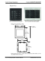
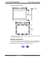
1
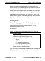
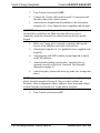
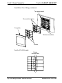
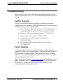
Crestron B-G2-FP & B-G3-FP
2 and 3 Gang Faceplates
Installation Guide
This document was prepared and written by the Technical Documentation department at:
Crestron Electronics, Inc.
15 Volvo Drive
Rockleigh, NJ 07647
1-888-CRESTRON
Crestron B-G2-FP & B-G3-FP
2 and 3 Gang Faceplates
Contents
2 and 3 Gang Faceplates: B-G2-FP & B-G3-FP
1
Introduction......................................................................................1
Physical Description ..............................................................1
Industry Compliance..............................................................3
Setup.................................................................................................4
Network Wiring .....................................................................4
Identity Code .........................................................................5
Installation .............................................................................5
Troubleshooting ...............................................................................9
Further Inquiries ....................................................................9
Future Updates.......................................................................9
Return and Warranty Policies ........................................................10
Merchandise Returns / Repair Service ................................10
CRESTRON Limited Warranty ..........................................10
Installation Guide - DOC. 8182
Contents • i
Crestron B-G2-FP & B-G3-FP
2 and 3 Gang Faceplates
2 and 3 Gang Faceplates:
B-G2-FP & B-G3-FP
Introduction
Two and three gang faceplates, B-G2-FP and B-G3-FP, are wall-mounted
plastic accessories that allow you to mount the CNX-B2/4/6/8/12 singlegang keypads in groups of two or three. For more information on the
keypads, refer to latest version of the Operations and Installation Guide
for the Single Gang Keypads, Doc. 8173. The number in the product’s
name corresponds to the number of gangs. Each of these units is
available in three colors (almond, black, and white). The suffix ‘A’, ‘B’,
and ‘W’, respectively denotes color, i.e. B-G2-FPB is a 2-gang black
unit. The 2 and 3 gang faceplates are specifically designed for the
Crestron keypads and will not accommodate third-party decorator-style
components.
Several different metal finishes are also available (must be purchased
separately) for mounting on the plastic faceplates. Finishes include
chrome, brushed gold, polished black, polished brass, polished gold,
stainless steel and primed.
Physical Description
Refer to the illustrations on pages 2 and 3. The faceplate unit consists of
a removable 2 or 3-gang plastic faceplate and a 2 or 3-gang detent plate.
The metal faceplates are slightly larger than the plastic units. Refer to the
NOTE on page 6 for metal faceplate installation instructions.
The number of buttons on a keypad can vary from 2, 4, 6, 8, or 12. Each
button assembly consists of a rear speaker, and a male port (standard
Cresnet network port labeled 24 Y Z G). The port provides operating
power and communications to/from the keypad
Installation Guide - DOC. 8182
2 and 3 Gang Faceplates: B-G2-FP & B-G3-FP • 1
2 and 3 Gang Faceplates
Crestron B-G2-FP & B-G3-FP
Physical Views
2-Gang black faceplate
with 12 and 8 black button keypads
Metal finish mounted on 3-gang faceplate
with 12 (2) and 8 black button keypads
2-Gang Faceplate/Detent Plate
4.724 in
(11.999 cm)*
0.220 in
(0.559 cm)*
4.762 in
(12.096 cm)*
4.636 in
(11.776 cm)
4.674 in
(11.872 cm)
* Metal faceplate dimensions – Height: 4.840 in (12.294 cm), Width: 4.800 in (12.192
cm), Depth: 0.283 in (0.719 cm)
2 • 2 and 3 Gang Faceplates: B-G2-FP & B-G3-FP
Installation Guide - DOC. 8182
Crestron B-G2-FP & B-G3-FP
2 and 3 Gang Faceplates
3-Gang Faceplate/Detent Plate
6.537 in
(16.604 cm)*
0.220 in
(0.559 cm)*
4.762 in
(12.096 cm)*
6.449 in
(16.381 cm)
4.674 in
(11.872 cm)
* Metal faceplate dimensions – Height: 4.840 in (12.294 cm), Width: 6.614 in (16.800
cm), Depth: 0.283 in (0.719 cm)
Industry Compliance
As of the date of manufacture, the keypads have been tested and found to
comply with specifications for CE marking and standards per EMC and
Radiocommunications Compliance Labelling (N11785).
Installation Guide - DOC. 8182
2 and 3 Gang Faceplates: B-G2-FP & B-G3-FP • 3
2 and 3 Gang Faceplates
Crestron B-G2-FP & B-G3-FP
Setup
Network Wiring
NOTE: When installing network wiring, refer to the latest revision of
the wiring diagram(s) appropriate for your specific system configuration,
available from the Downloads | Product Manuals | Software and Wiring
Diagrams section of the Crestron website (www.crestron.com).
When calculating the wire gauge for a particular Cresnet run, the length
of the run and the power factor of each network unit to be connected
must be taken into consideration. If Cresnet units are to be daisy-chained
on the run, the power factor of each unit to be daisy-chained must be
added together to determine the power factor of the entire chain. If the
unit is a home-run from a Crestron system power supply network port,
the power factor of that unit is the power factor of the entire run. The
length of the run in feet and the power factor of the run should be used in
the following resistance equation to calculate the value on the right side
of the equation.
Resistance Equation
R < 40,000
L x PF
Where: R = Resistance (refer to table below).
L = Length of run (or chain) in feet.
PF = Power factor of entire run (or chain).
The required wire gauge should be chosen such that the resistance value
is less than the value calculated in the resistance equation. Refer to the
table below.
Wire Gauge Values
RESISTANCE (R)
WIRE GAUGE
4
16
6
18
10
20
15
22
13
Doubled CAT5
8.7
Tripled CAT5
4 • 2 and 3 Gang Faceplates: B-G2-FP & B-G3-FP
Installation Guide - DOC. 8182
Crestron B-G2-FP & B-G3-FP
2 and 3 Gang Faceplates
NOTE: All Cresnet wiring must consist of two twisted-pairs. One
twisted pair is the +24V conductor and the GND conductor and the other
twisted pair is the Y conductor and the Z conductor.
NOTE: When daisy-chaining Cresnet units, strip the ends of the wires
carefully to avoid nicking the conductors. Twist together the ends of the
wires that share a pin on the network connector, and tin the twisted
connection. Apply solder only to the ends of the twisted wires. Avoid
tinning too far up the wires or the end becomes brittle. Insert the tinned
connection into the Cresnet connector and tighten the retaining screw.
Repeat the procedure for the other three conductors.
Identity Code
Every equipment and user interface within the network requires a unique
identity code (NET ID). Refer to latest version of the Operations and
Installation Guide for the Single Gang Keypads, Doc. 8173, for
procedures on setting the NET ID.
Installation
NOTE: For simplicity, the following procedure is for a 2-gang unit.
Tools/hardware required
2-gang Plastic Faceplate (supplied with B-G2-FP)
2-gang Detent Plate (supplied with B-G2-FP)
(2) Single Gang Keypads (supplied separately), which includes:
Buttons
(2) Dividers
(4) 1 in. panhead phillips screws
(4) 3/16 in. flathead phillips screws
Cresnet network cable (supplied separately)
Phillips screwdriver (supplied by other)
After the Cresnet network wiring has been installed and verified, use the
following procedure to install the keypads in a standard, 2-gang electrical
box (refer to illustrations on pages 7 and 8).
Installation Guide - DOC. 8182
2 and 3 Gang Faceplates: B-G2-FP & B-G3-FP • 5
2 and 3 Gang Faceplates
Crestron B-G2-FP & B-G3-FP
1.
Turn Cresnet system power OFF.
2.
Connect the Cresnet cable to the keypads’ Cresnet ports and
the other ends to the control system.
3.
Attach the two keypad button assemblies to the detent plate
using the (4) 3/16 in. flathead screws (supplied with keypads).
CAUTION: Excess wire that is pinched between the keypad and
electrical box could short out. Make sure that all excess wire is
completely inside the electrical box and not between the box and the
keypad.
4.
5.
Make sure 2-gang unit is oriented as marked with keypads’
arrows at top, and place unit in the electrical box.
Attach units using the (4) 1 in. panhead screws (supplied with
keypads).
6.
Attach buttons with LED window oriented upward to match
each LED indicator.
7.
Attach dividers making sure dividers’ interlock tabs are
oriented correctly (refer to the “Interlock Tabs Example”
illustration on page 8).
8.
Attach faceplate (orient with arrow up, make sure it snaps into
place).
NOTE: If you are installing a metal 2-gang faceplate, carefully clean
plastic faceplate mentioned in step 8, (leave no dust or debris on
faceplate), observe alignment, remove adhesive liners from inner surface
of metal faceplate and mount over 2-gang plastic faceplate.
9.
Turn Cresnet system power ON.
6 • 2 and 3 Gang Faceplates: B-G2-FP & B-G3-FP
Installation Guide - DOC. 8182
Crestron B-G2-FP & B-G3-FP
2 and 3 Gang Faceplates
Installation View 2-Gang
Button assembly
2 gang detent
3/16 in. flathead
Two gang electrical box
(2.5 in. depth recommended)
1 in. panhead
Two gang detent
with button assemblies
Installation Guide - DOC. 8182
2 and 3 Gang Faceplates: B-G2-FP & B-G3-FP • 7
2 and 3 Gang Faceplates
Crestron B-G2-FP & B-G3-FP
Installation View 2-Gang (continued)
Two gang detent
Removable buttons
Faceplate
Button assemblies
Divider
Interlock Tabs Example
Divider
Interlock tabs
8 • 2 and 3 Gang Faceplates: B-G2-FP & B-G3-FP
Installation Guide - DOC. 8182
Crestron B-G2-FP & B-G3-FP
2 and 3 Gang Faceplates
Troubleshooting
Refer to latest version of the Operations and Installation Guide for the
Single Gang Keypads, Doc. 8173, for troubleshooting information on the
keypads.
Further Inquiries
If after reviewing this Installation Guide, you cannot locate specific
information or have questions, please take advantage of Crestron's award
winning customer service team by calling:
• In the US and Canada, call Crestron’s corporate headquarters at
1-888-CRESTRON [1-888-273-7876] or 1-201-767-3400.
• In Europe, call Crestron International at +32-15-50-99-50.
• In Asia, call Crestron Asia at +852-2341-2016.
• In Latin America, call Crestron Latin America at
+5255-5093-2160.
• In Australia and New Zealand, call Creston Pacific at
+613-9480-2999
Future Updates
As Crestron improves functions, adds new features, and extends the
capabilities of the 2 and 3 gang faceplates, additional information may be
made available as manual updates. These updates are solely electronic
and serve as intermediary supplements prior to the release of a complete
technical documentation revision.
Check the Crestron website (www.crestron.com) periodically for manual
update availability and its subjective value. Updates are available from
the Download | Product Manuals section and are identified as an
“Addendum” in the Download column.
Installation Guide - DOC. 8182
2 and 3 Gang Faceplates: B-G2-FP & B-G3-FP • 9
2 and 3 Gang Faceplates
Crestron B-G2-FP & B-G3-FP
Return and Warranty Policies
Merchandise Returns / Repair Service
1.
No merchandise may be returned for credit, exchange, or service without prior
authorization from CRESTRON. To obtain warranty service for CRESTRON products,
contact the factory and request an RMA (Return Merchandise Authorization) number.
Enclose a note specifying the nature of the problem, name and phone number of contact
person, RMA number, and return address.
2.
Products may be returned for credit, exchange, or service with a CRESTRON Return
Merchandise Authorization (RMA) number. Authorized returns must be shipped freight
prepaid to CRESTRON, Cresskill, N.J., or its authorized subsidiaries, with RMA number
clearly marked on the outside of all cartons. Shipments arriving freight collect or without
an RMA number shall be subject to refusal. CRESTRON reserves the right in its sole and
absolute discretion to charge a 15% restocking fee, plus shipping costs, on any products
returned with an RMA.
3.
Return freight charges following repair of items under warranty shall be paid by
CRESTRON, shipping by standard ground carrier. In the event repairs are found to be
non-warranty, return freight costs shall be paid by the purchaser.
CRESTRON Limited Warranty
CRESTRON ELECTRONICS, Inc. warrants its products to be free from manufacturing defects in
materials and workmanship under normal use for a period of three (3) years from the date of
purchase from CRESTRON, with the following exceptions: disk drives and any other moving or
rotating mechanical parts, pan/tilt heads and power supplies are covered for a period of one (1)
year; touchscreen display and overlay components are covered for 90 days; batteries and
incandescent lamps are not covered.
This warranty extends to products purchased directly from CRESTRON or an authorized
CRESTRON dealer. Purchasers should inquire of the dealer regarding the nature and extent of the
dealer's warranty, if any.
CRESTRON shall not be liable to honor the terms of this warranty if the product has been used in
any application other than that for which it was intended, or if it has been subjected to misuse,
accidental damage, modification, or improper installation procedures. Furthermore, this warranty
does not cover any product that has had the serial number altered, defaced, or removed.
This warranty shall be the sole and exclusive remedy to the original purchaser. In no event shall
CRESTRON be liable for incidental or consequential damages of any kind (property or economic
damages inclusive) arising from the sale or use of this equipment. CRESTRON is not liable for
any claim made by a third party or made by the purchaser for a third party.
CRESTRON shall, at its option, repair or replace any product found defective, without charge for
parts or labor. Repaired or replaced equipment and parts supplied under this warranty shall be
covered only by the unexpired portion of the warranty.
Except as expressly set forth in this warranty, CRESTRON makes no other warranties, expressed
or implied, nor authorizes any other party to offer any other party to offer any warranty, including
any implied warranties of merchantability or fitness for a particular purpose. Any implied
warranties that may be imposed by law are limited to the terms of this limited warranty. This
warranty statement supercedes all previous warranties.
Trademark Information
All brand names, product names, and trademarks are the sole property of their respective owners.
Windows is a registered trademark of Microsoft Corporation. Windows95/98/Me and
WindowsNT/200 are trademarks of Microsoft Corporation.
10 • 2 and 3 Gang Faceplates: B-G2-FP & B-G3-FP
Installation Guide - DOC. 8182
Crestron B-G2-FP & B-G3-FP
2 and 3 Gang Faceplates
This page intentionally left blank.
Installation Guide - DOC. 8182
2 and 3 Gang Faceplates: B-G2-FP & B-G3-FP • 11
Crestron Electronics, Inc.
15 Volvo Drive Rockleigh, NJ 07647
Tel: 888.CRESTRON
Fax: 201.767.7576
www.crestron.com
Installation Guide - DOC. 8182
07.02
Specifications subject to
change without notice.