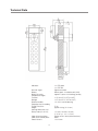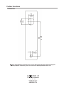
1
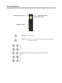
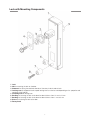
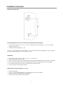
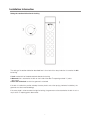
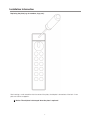
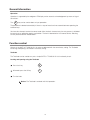
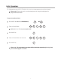
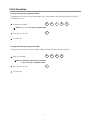
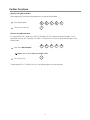
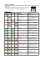
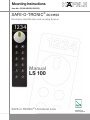
Mounting Instructions Item No.: 231.98.000/001/002/003 SAFE-O-TRONIC® access Electronic Identification and Locking System Manual LS 100 SAFE-O-TRONIC® LS Cabinet Lock Dimensions in mm Inches are approximate Notes on this manual ® Copyright 2010 by Document number: Schulte-Schlagbaum AG Nevigeser Straße 100-110 D-42553 Velbert Phone: +49 2051 2086-0 http:/www.sag-schlagbaum.com 6-703-2 34R1.0 • This manual replaces all previous versions. • The details in this manual are subject to change without prior notification. • The compilation of the information in this manual is carried out to the best of our knowledge. Schulte-Schlagbaum AG does not assume any liability for the correctness and completeness of the details in this manual. In particular, Schulte-Schlagbaum AG cannot be held liable for consequential damages on account of faulty or incomplete details. • Relaying and duplication of this document and the exploitation and communication of its contents are not permitted unless expressly allowed. Violations shall obligate to provide compensation for damages. All rights reserved in the event of patent grant or registration of a utility model or design. Means of depiction The following means of depiction are used in this manual: Notice Please observe this important information. Handling instructions These mark a work step during user input. SAFE-O-TRONIC® is a registered trademark of Schulte-Schlagbaum AG. Safety and warning notes Please read before initial operation. • This manual describes the initial operation and operation of a SAFE-O-TRONIC® LS 100. • The equipment must only be used for the purpose intended by the manufacturer. • Please keep the instruction manual in an easily accessible place. • Unauthorized amendments and the use of spare parts and auxiliary devices that are not sold or recommended by the manufacturer of the equipment can cause fires, electric shocks and injuries. The manufacturer will not be liable. • Repair work must only be carried out by the manufacturer. • The warranty provisions of the manufacturer as amended on the date of purchase shall apply to the equipment. Liability will not be assumed for unsuitable and automatic compilation of parameters for a device or unsuitable application of a device. • The operating company shall bear the responsibility that the device is installed and connected according to recognized technical rules in the country of installation as well as other valid regulations. 2 Table of Contents Notes on this manual..................................................................................... Safety and warning notes............................................................................. Table of contents............................................................................................ Control elements............................................................................................ Lock with mounting components................................................................. Installation information................................................................................. Preparation of the door.......................................................................................... Installation........................................................................................................... Replacement of the rotary knob (as needed)............................................................... Setting the rotational direction for locking.................................................................. Replacing the plate (e.g. for numbers, logo, etc.)......................................................... General information....................................................................................... Capacitive keypad................................................................................................. UserCode............................................................................................................ MasterCode1........................................................................................................ MasterCode2........................................................................................................ Code overview...................................................................................................... Operation............................................................................................................ Function control............................................................................................. Initial operation.............................................................................................. Programming MasterCode2.................................................................................... Locking and opening using MasterCode2................................................................... Locking and opening using the UserCode.................................................................. Further functions........................................................................................... Altering MasterCode2............................................................................................ Programming MasterCode1.................................................................................... Opening using MasterCode1.................................................................................... Release using MasterCode2.................................................................................... Further information........................................................................................ LED display.......................................................................................................... Troubleshooting / operating errors............................................................................ Replacing the battery............................................................................................. Battery monitoring / battery alarm............................................................................ Maintenance and care........................................................................................... Technical Data..................................................................................................... Drilling template................................................................................................... 3 2 2 3 4 5 6 6 6 6 7 8 9 9 9 9 9 9 10 10 11 11 12 12 13 13 14 15 15 16 16 17 17 17 17 18 19 Control Elements LED display red / green Exchangeable plate Rotary knob Capacity keypad √ OK key: Finish of Code entry Abort key: Code entries or programming operations can be rejected by X pressing the abort key 1 2 3 4 5 6 7 8 9 0 Keys 1, 2, 3, 4, 5, 6, 7, 8, 9, 0: Number keys for Code entry 4 Lock with Mounting Components 1 2 3 4 5 6 7 8 9 Lock Nut for mounting the lock on the door Grommet for setting the rotational direction of the rotary knob in order to lock Locking cam (A cropped or hook-shaped locking lever can also be used depending on the properties and condition of the cabinet.) Fastening bolt for locking lever Bushing for fastening the lock to the door for door thickness from 10 mm to 18 mm Bushing for fastening the lock to the door for door thickness from 1 mm to 9 mm Screw for fastening the lock to the door Rotary knob 5 Installation Information Preparation of the door The following holes must exist in the door corresponding to the drawing: 1. Punched hole, dimensions 19.1 mm / 16 mm. A round hole with a diameter of 19.1 mm can also be drilled at this position. 2. Round hole with a diameter of 7 mm. As soon as the first hole exists, as described in 1, the 7 mm round hole can be drilled by using a drilling template (e.g. the drilling template at the end of the manual). Installation 1. 2. 3. 4. 5. 6. Insert the lock (1) into the two holes 19.1 mm / 16 mm and 7 mm Fasten the lock (1) using the nut (2) Screw on the lock (1) using the screw (8) and the bushing (6 or 7) depending on the thickness of the door Fasten the grommet (3) for setting the rotational direction and the locking cam (4) using the bolt (5) Test the lock function by means of the TestCode when the door is open Test the function when the door is closed Replacement of the rotary knob (as needed) 1. Remove the bolt (5). 2. Use a TG 10 screwdriver to loosen the fastening screw for the rotary knob by inserting through the threaded hole for the bolt (5). 3. Fasten the new rotary knob in reversed order. 6 Installation Information Settng the rotational direction for locking The setting of the rotational direction described here is for a lock with a rotary knob that is turned to the left for locking. 1 Lock marked with left handed rotational direction for locking 2 Grommet that is attached to the lock on the inside of the door. The opening marked “L” points downwards. 3 Rear side of the lock to which the grommet is attached. If the lock is installed in a position whereby the rotary knob is not at the top (e.g. horizontal installation), the grommet must be turned accordingly. If the rotary knob is to be turned to the right for locking, the grommet must be attached to the lock in such a way that the “R” opening points downwards. 7 Installation Information Replacing the plate (e.g. for numbers, logo, etc.) After inserting a small screwdriver into the center of the plate, the old plate is levered out of the lock. A new plate can then be snapped in. Notice: The old plate is destroyed when the plate is replaced. 8 General Information Capacitive keypad The SAFE-O-TRONIC® LS 100 uses a capacitive keypad. Notice: The capacitive keypad cannot be operated if you are wearing gloves. UserCode The UserCode serves locking or opening of the cabinet or locker by the user. Any four-digit code can be programmed as the UserCode. MasterCode1 MasterCode1 serves the plant operator to open the locker. It is intended for employees with restricted locking authorizations. After being opened, the lock is blocked for the entry of a new UserCode and has to be released with the help of the MasterCode2. A 5 digit code can be programmed as MasterCode1. If the employees are only aware of the MasterCode1, they are protected against suspicion in cases of hidden thefts. It means if there is a theft and the compartment has been locked again, the employees cannot come into question as offenders. Notice: MasterCode1 cannot be programmed with 0 as the first number! MasterCode2 MasterCode2 can be used by the operator of the facility at any time to open and close the compartment or release the lock. A 5 digit code can be programmed as MasterCode2. Notice: MasterCode2 cannot be programmed with 0 as the first number! Code overview The following table contains an overview of the various codes. UserCode MasterCode1 MasterCode2 4-digit x - 5 digit x x Open x x(*) x Close x x (*) Notice: After using MasterCode1 to open the locker, the lock must be released by entering MasterCode2 (see page 15). 9 General Information Operation Operation is supported by the red/green LED display and an acoustic acknowledgement by means of signal transmitters. The X key can be used to abort an input procedure. The procedure is aborted automatically if there is a stop of more than three seconds between operating the individual keys. You have four attempts to enter the correct code. After the fourth incorrect entry the entry process is disabled for one minute as protection against manipulation. The lock is blocked after 100 incorrect entries. Blocking can only be released with MasterCode2. Function control All locks in the SAFE-O-TRONIC® LS 100 series are delivered with the same factory setting. The TestCode for locking and opening is activated in the factory setting. TestCode The TestCode can be used to carry out a simple SAFE-O- TRONIC® LS 100 functionality check. Locking and opening using the TestCode ► Press the 0 key 0 ► Afterwards press the OK key √ ► Turn the knob Notice: The TestCode is retained until initial operation. 10 Initial Operation For initial operation every SAFE-O-TRONIC® LS 100 lock has to be programmed using MasterCode2. Please note: Please make sure that unauthorized persons do not gain knowledge of the programmed MasterCode2. Programming MasterCode2 ► Press the OK and abort keys simultaneously ► Enter new MasterCode2 Press the OK key ► Enter new MasterCode2 one more time ► Press the OK key 3 5 X 1 9 7 1 9 7 Notice: 3, 5, 1, 9, 7 is only an example code! ► and √ √ 3 5 √ Please note: The programming procedure will be terminated automatically if a key is not pressed within approx. 3 seconds. 11 Initial Operation Locking and opening using MasterCode2 The operator of the facility can use MasterCode2 at any time to open or lock the locker fitted with the SAFEO-TRONIC® LS 100. ► 3 Entering MasterCode2 ► 5 1 9 7 Notice: 3, 5, 1, 9, 7 is only an example code! √ Then press the OK key ► Turn the knob Locking and opening using the UserCode The user has the possibility to enter a random 4-digit UserCode and lock and open the locker. 9 ► Enter the UserCode Notice: A four-digit code must be entered! 9, 0, 6, 0 is only an example code! √ ► Then press the OK key ► Turn the knob 12 0 6 0 Further Functions Altering MasterCode2 ► Press the OK and abort keys simultaneously √ and ► Enter active MasterCode2 3 5 1 9 7 2 7 3 2 7 3 Notice: 3, 5, 1, 9, 7 is only an example code! ► Press the OK key √ ► Press 2 (“2” for MasterCode2) 2 ► Press the OK key ► Enter new MasterCode2 X √ 4 8 Notice: 4, 8, 2, 7, 3 is only an example code! ► Press the OK key ► Enter new MasterCode2 one more time ► Press the OK key √ 4 8 √ 13 Further Functions Programming MasterCode1 MasterCode1 is not activated in the factory and must be programmed by the operator. Notice: An identical code for MasterCode1 and MasterCode2 is not permitted. ► Press the OK and abort keys simultaneously ► Enter active MasterCode2 √ 3 5 1 9 7 6 0 9 6 0 9 Notice: 3, 5, 1, 9, 7 is only an example code! ► Press the OK key √ ► Press 1 (“1” for MasterCode1) 2 ► Press the OK key √ ► Enter new MasterCode1 X and 9 0 Notice: 9, 0, 6, 0, 9 is only an example code! ► Press the OK key ► Enter new MasterCode1 one more time ► Press the OK key √ 9 0 √ 14 Further Functions Opening using MasterCode1 After programming, a locker can be opened with the help of MasterCode1. ► Enter MasterCode1 3 ► Then press the OK key √ 5 1 9 7 Release using MasterCode2 If a compartment that is fitted with a SAFE-O-TRONIC® LS 100 is opened using MasterCode1, it stays blocked for the entry of a UserCode. The SAFE-O-TRONIC® LS 100 then has to be released again using MasterCode2. 9 0 6 0 9 Enter active MasterCode2 ► ► Notice: 3, 5, 1, 9, 7 is only an example code! Press the OK key √ The blocked SAFE-O-TRONIC® LS 100 is now released again for further operation. 15 Further Information LED Display All important actions and operating conditions are indicated by the LED display and are intended to contribute to finding the causes of failures and operating errors. The following table lists the meaning of the individual signals. Status messages: green red green red Display Flashing rapidly 1 second Action Programming mode Mastercode 1 & 2 Blocking time (one minute) is active. Wrong Code entered four times Key entry 1 second Abort key (“X”) pressed LEDs flash in turn three times 2 seconds Handling error, the rotary knob was not operated within the released period Waiting for rotary knob to be operated Lock has been locked / programming successful Lock has been unlocked 1/2 second Code accepted Every 3 seconds Alternate 1 second 3 seconds Internal malfunction / lock may have to be replaced Red LEDs light up first, Blocking triggered by then the green LEDs, for MasterCode 1, cancelled 1/2 a second in each case by means of MasterCode 2 LEDs flash together three times LEDs flash together twice LEDs flash in turn three times LEDs flash three times 16 Code entry rejected, as blocking by MasterCode 1 active Warning: battery replacement is required shortly Battery must be replaced immediately; lock can no longer be operated MasterReset carried out Troubleshooting / Operating Errors You are able to see errors and operating errors in the status messages of the LED display and then correct them accordingly. Reset should be carried out in the case that other non-defined conditions arise and the lock does not operate flawlessly even though the battery has been replaced. This resets the lock to factory default settings and all programming is deleted. You can obtain the instructions for this via the address or telephone number stated on page 2. Replacing the battery 1. Loosen the screw on the side of the cover using a TG 6 screwdriver. 2. Open the battery compartment and remove the battery pack. Disconnect the two-pole plug-in connector from the battery pack. 3. Connect the new battery pack to the plug-in connector and insert the battery into the housing. 4. Close the battery compartment and screw down. Codes are not deleted when a battery is replaced. Notice: Please dispose the empty battery pack properly in accordance with the valid environmental regulations! Battery monitoring / battery alarm Automatic battery monitoring on the SAFE-O-TRONIC®-LS 100 ensures that a SAFE-O-TRONIC®-LS 100 with inadequate battery voltage can no longer be operated. There is an advance warning when all the LEDs flash twice. In this case it is recommended to replace the battery. An alarm is triggered after a while if the battery is not replaced. This is indicated when the red and green LEDs light up in turn three times. The battery must now be replaced. In this instance the compartment can only be opened but no longer locked. The lock must only be operated using batteries approved by Häfele. The use of non-approved batteries can lead to malfunctions and lock damage. Maintenance and care The SAFE-O-TRONIC® LS 100 is maintenance-free. In no case should the lock be oiled or greased with lubricants containing mineral oil. Only use non-stick, residue-free cleaning agents and disinfectants for cleaning purposes. Do not use any heavy cleaning agents, acids or lyes when caring for the product. Also do not use a pressure cleaner. It is also not recommended to spray-wash the locks, for example using a hose. 17 Technical Data Indicators: Acoustic signal: Battery: Battery life cycle: Temperature ranges Function: Storage: Relative humidity: Protection class according To DIN EN 60529: Weight: Housing dimensions incl. Rotary knob (H x W x D): Color of housing frame: Color of the control panel: Door thickness: 18 2 x LED green 2 x LED red Signal transmitter Battery pack: 3 x alkaline cells (AAA) Approx. 3 years at 30 lockings per day -10˚C to +65˚C (14˚F to 149˚F) -25˚C to +65˚C (-13˚F to 149˚F) 10 – 90% non-condensing IP 43 approx. 300 g (10 1/2 oz.) 151 mm x 38 mm x 33 mm (5 15/16” x 1 1/2” x 1 5/16”) Similar to RAL 9006 (white aluminum) Black 1 to 19 mm Further Functions Technical Data Notice: Depending on the printer there can be dimensional deviations when printing this drilling template. Therefore, please re-measure the drilling template before use! 3901 Cheyenne Drive P.O. Box 4000 Archdale, NC 27263 1-800-423-3531 www.hafele.com