1
“SPEEDY” PERSONAL
SPEED RADAR KIT
Ramsey Electronics Model No.
SG7
YOU BE THE COP! “CLOCK” CARS, BIKES, PLANES, HORSES,
JOGGERS, VIRTUALLY ANYTHING THAT MOVES! WORKS ON THE
SAME PRINCIPLE AS POLICE UNITS COSTING THOUSANDS MORE.
IDEAL FOR LEARNING AND TEACHING RADAR THEORY.
•
Direct readout in Miles, Kilometers or Feet per second
•
Operates on 12 volts DC
•
1/4 mile range with average size car
•
Better than 2 miles per hour accuracy, reads to over 200 MPH
•
Operates on 2.6GHz - no license needed
•
Earphone output to actually hear Doppler shift
•
The Nation’s #1 science fair project!
•
Clear, concise step-by-step instructions guide you to a finished kit
that not only works FIRST time - but you’ll also learn!
•
Complete kit includes case and cables - just add two coffee or juice
cans
•
Sets off cheap radar detectors - lots of highway fun!
SG7• 1
RAMSEY TRANSMITTER KITS
• FM100B Professional FM Stereo Transmitter
• FM25B Synthesized Stereo FM Transmitter
• MR6 Model Rocket Tracking Transmitter
• TV6 Television Transmitter
RAMSEY RECEIVER KITS
• FR1 FM Broadcast Receiver
• AR1 Aircraft Band Receiver
• SR2 Shortwave Receiver
• SC1 Shortwave Converter
RAMSEY HOBBY KITS
• SG7 Personal Speed Radar
• SS70A Speech Scrambler
• BS1 “Bullshooter” Digital Voice Storage Unit
• AVS10 Automatic Sequential Video Switcher
• WCT20 Cable Wizard Cable Tracer
• LC1 Inductance-Capacitance Meter
RAMSEY AMATEUR RADIO KITS
• DDF1 Doppler Direction Finder
• HR Series HF All Mode Receivers
• QRP Series HF CW Transmitters
• CW7 CW Keyer
• CPO3 Code Practice Oscillator
• QRP Power Amplifiers
RAMSEY MINI-KITS
Many other kits are available for hobby, school, Scouts and just plain FUN. New
kits are always under development. Write or call for our free Ramsey catalog.
SG7 PERSONAL SPEED RADAR KIT INSTRUCTION MANUAL
Ramsey Electronics publication No. MSG7 Revision 1.2
First printing: February 1995
COPYRIGHT 1994 by Ramsey Electronics, Inc. 590 Fishers Station Drive, Victor, New York
14564. All rights reserved. No portion of this publication may be copied or duplicated without the
written permission of Ramsey Electronics, Inc. Printed in the United States of America.
SG7• 2
Ramsey Publication No. MSG7
Price $5.00
KIT ASSEMBLY
AND INSTRUCTION MANUAL FOR
SG7 PERSONAL
SPEED RADAR
TABLE OF CONTENTS
Work involved in building the SG7........ 4
Doppler description .............................. 5
Parts list ............................................... 7
Signal cable assembly ......................... 9
Power supply notes ............................ 10
LED schematic diagram ..................... 12
LED unit PC layout ............................. 13
Assembling the LED unit .................... 14
Assembling the microwave unit .......... 20
Microwave unit PC layout ................... 11
Shield assembly ................................. 24
Microwave oscillator PC board ........... 26
Can selection and details ................... 27
Testing and calibration ....................... 29
Troubleshooting hints ......................... 31
SG7 statistics and specs .................... 32
Ramsey kit warranty........................... 34
RAMSEY ELECTRONICS, INC.
590 Fishers Station Drive
Victor, New York 14564
Phone (585) 924-4560
Fax (585) 924-4555
SG7• 3
PLEASE, PLEASE READ THIS!
THANK YOU for purchasing the SG7 Speedy Radar Gun. This is a kit project
that we're especially proud of. We've packed a lot of value into it, and we
know you have paid good money for it and that you sure do expect it to work.
Speedy will be a very satisfying project for you - IF you are willing to follow our
directions carefully. This is definitely not one of those kits where you can
expect to just put some parts on a board and tinker as you go along.
Mechanical details are just as critical as correct component soldering.
•
•
•
•
•
There are several reasons why following directions are so
important for this kit. Of course, you and I both want it to "work". In
addition:
Both you and I want the Display PC board to fit correctly in its
custom-made case. For example, if you jump ahead and install the
electrolytic capacitors in the conventional way, the board will NOT
fit in the case.
Both you and I want Speedy to LOOK GOOD when it's finished.
Both you and I want it to be mechanically durable, so it can be
USED reliably when and where you want to use it.
Please realize that physical and mechanical details are MUCH
more critical at 2600 MHz than in frequency ranges more familiar to
most electronics and radio experimenters!
Our directions are designed to help you accomplish all these goals. Please
follow them carefully!
BUILDING THE SG7 - A LOOK AT THE WORK TO DO:
Since there are a variety of steps in completing your Personal Radar, lets look
over the big picture briefly. An operational SG7 consists of three basic
devices: the LED Speed Readout unit, the Microwave Oscillator-Antenna unit,
and a convenient 12 volt power pack (200mA or more) provided by you.
The SG7A Speed Readout unit involves fairly conventional PC board
soldering. Following our directions is VERY important for getting a good fit of
the board into its custom case so that it fits correctly.
The SG7B Microwave Oscillator-Antenna PC board involves a mix of both
thru-the-board leads and surface soldering typical of UHF and microwave
designs. Even though it's not a quickie "stick-in-the-parts" job, it goes together
more easily than you might think, and we'll be with you every step of the way.
A pre-cut piece of real, honest, shiny tin is supplied for use in forming a shield
and casing around the component side of the Microwave Oscillator board. It is
SG7• 4
soldered in place very easily, so long as its creases are formed carefully.
The oscillator board, enclosed in its tin shield, is soldered to a metal can
assembly that has been prepared with TLC (Tender Loving Care). You will find
that both the oscillator shield and the can will solder very easily. After all, tin is a
major ingredient of solder. A 1.1" length of buss wire (supplied) extends through
a hole in the can from the oscillator board to serve as the 2600MHz antenna in
conjunction with the can itself!
A shielded 2-conductor cable and plug set (all parts supplied in the kit)
interconnects the LED Speed Counter unit and the radar gun itself.
Your SG7 Kit includes everything needed except 12V battery pack, battery
cable (a correct DC power plug IS supplied), and the two metal cans needed to
form the radar gun antenna housing. Included with your kit are the case and
hardware along with the front panel graphic for a nifty looking, finished off unit.
We'll give you a few ideas on how to make your SG7 Personal Speed Radar
unit as portable and practical as possible, but we know you will come up with
ideas of your own, too.
JUST IN CASE YOU DIDN'T KNOW...
There are many kinds of "radar" (Radio Detecting and Ranging) systems, most
of them associated with aviation and military applications. These types of
radars bring up images of domes, spinning antennas and radar screens. Your
SG7 SPEEDY is a type of portable radar system, typical of speed monitoring
equipment used in law enforcement, sports, and boating which rely on the
"Doppler effect".
The Doppler effect, first investigated by Austrian physicist C.J. Doppler in 1842,
is observed in ANY kind of wave motion: sound, light or radio waves. Here is a
definition to chew on:
The Doppler effect is the observed change in frequency of a waveform caused
by a time rate of change due to the effective distance traveled by the wave
between the source and the point of observation. As the time rate of distance
between you and a source of constant vibration decreases, the received
frequency is greater. As the time rate of distance increases, the frequency
decreases.
Imagine in your mind what you actually hear while a race car zooms past your
fixed position. Can you hear that change of "varoooom..." pitch and mimic it?
Now, ask yourself how the car sounded to the driver all along as you heard the
changing pitch of the zoom! This is one common example of the Doppler effect.
The whistle of a passing train is another example.
SG7• 5
A Doppler radar measures the velocity of a moving object by doing
something useful with the detected shift in carrier frequency of the returned
or "echo" signal. The shift is proportionate to the speed of the object as it
approaches or moves away.
An easy way to understand what a Doppler radar actually does is to think
about how one of our other kits actually works- the much simpler but fun and
practical MD-3 Microwave Motion Detector or "intrusion Alarm". Like the
SG7, the MD-3 employs a microwave oscillator radiating a microwave signal
from a tiny wire antenna. (The MD-3 runs at 960MHz, rather than in the
2.6GHz spectrum of the SG7.)
Picture what is really going on with the MD-3 turned on in a room where
every object is still. The receiver portion of the circuit hears all the echoes,
and they all stay the same. If someone enters the space, the receiver
detects the returned or echo signal at a frequency different enough to trigger
its switching or alarm circuitry. While it does not measure or count, the
receiver has detected the Doppler shift! For each mile per hour that a target
is traveling toward the radar speed gun, the echo signal will be shifted 7.76
Hertz higher. If an oncoming car is traveling at 50 mph, the echo or reflected
signal will be 388 Hz higher than the original, and it is this difference which
the frequency counter converts to a miles-per-hour reading. If the oncoming
target's speed varies, the SG7 counter can update the readout every 1/7
second. Other readouts such as Kilometers/Hour are possible by changing
R21 in series with the Calibration potentiometer.
The earphone jack is much more than a novelty. This audio output is the FM
modulated Doppler shift difference in Hertz between the transmitted signal
and the reflected signal. In addition to "just listening" to the output
frequency, you can connect this audio sampling of the Doppler shift to an
interesting variety of other devices including standard Ramsey Frequency
Counters, or (for higher speeds) audio tone decoders such as our
inexpensive TD-1 Tone Decoder Kit. For example, if the TD-1 is adjusted to
trigger with a 621 Hz input tone, it might be used with the SG7 to sound an
alarm if a target hits 80 Mph! (80 X 7.76 = 620.8 Hz). Pretty neat, huh?
The World Beyond 99 MPH?
The SG7's two-digit LED display directly counts to 99 MPH or other
calibrated unit of speed/time. At 100 MPH and beyond, the counter "rolls
over" just like the gas pumps (and drivers) that never dreamed that fuel
would go above a dollar a gallon. We do not have hard data on how far
beyond 100 MPH you can continue to count accurately. However, you can
find out by correlating the monitored Doppler shift frequency with the
indicated SG7 two-digit readings and known high-speed targets such as
airplanes on approach.
SG7• 6
PARTS LIST:
LED SPEED READOUT PC BOARD:
CAPACITORS
1 100pF capacitor (marked 100 or 101) (C16)
1 2200pF disc capacitor (marked .0022 or 2200 or 222) (C5)
1 .005µF capacitor (marked .005 or 5000 or 502) (C1)
2 .001µF capacitors (marked .001 or 102) (C3,C11)
6 .01µF capacitors (marked .01 or 103 or 10nf) (C4,13,15,17,18,19)
2 .047 or .05µF capacitors (marked .047 or 473, .05 marked .05 or
503) (C7,C8)
5 10µF electrolytic (C6,9,10,14,21)
1 22µF electrolytic (C20 - see text)
1 33µF electrolytic (C20- see text)
2 100 or 220µF electrolytic (C2,C12)
RESISTORS
1 100 ohm [brown-black-brown] (R11)
3 220 ohm [red-red-brown] (R23,24,27)
1 3.3K ohms [orange-orange-red] (R12)
2 4.7K ohms [yellow-violet-red] (R25,R26)
4 10K ohms [brown-black-orange] (R5,14,17,21)
2 22K ohms [red-red-orange] (R8,R9)
7 47K ohms [yellow-violet-orange] (R1,2,3,4,13,18,20)
5 100K ohms [brown-black-yellow] (R7,15,16,28,19)
1 1 megohm [brown-black-green] (R6)
1 2.2K ohms potentiometer (GAIN, R10)
1 10K ohms potentiometer (CALIBRATION, R22)
SEMICONDUCTORS
1 2N3904 NPN transistor (Q1)
1 LM324 Quad op-amp IC (U1)
1 4093 Quad Schmitt trigger NAND IC (U2)
1 4011 Quad NAND IC (U3)
1 4518 Dual BCD decade counter IC (U4)
2 4511 BCD to 7 segment LED driver IC (U5,U6)
1 1N4002 1 amp diode (D2)
1 1N4148 glass bead signal diode (D1)
2 7-segment LED display (U7,U8)
SG7• 7
OTHER COMPONENTS
1 SG7 printed circuit board
1 Case kit
1 Miniature stereo (signal) jack (J1)
4 case screws
1 Subminiature phone jack (J2)
4 3/8" threaded standoffs
1 DC coaxial power jack (J3)
8 #4 screws
1 Stereo (signal) plug
1 front panel decal
1 power plug (may include wire)
1 5 feet of 2 conductive shielded hookup wire
MICROWAVE OSCILLATOR PC BOARD:
CAPACITORS
3 .01µF disc capacitor (marked .01 or b103 or 10nf) (C1,2,6)
1 .001µF SMT chip capacitor (C7, factory-installed on board)
2 1µF electrolytic (C4,C5)
1 220µF electrolytic (C3)
RESISTORS
2 100 ohms [brown-black-brown] (R4,R5)
1 1K ohms [brown-black-red] (R3)
2 10K ohms [brown-black-orange] (R1,R6)
1 1 megohm [brown-black-green] (R2)
SEMICONDUCTORS
1 2N3904 NPN transistor (Q1)
1 NE021 microwave transistor (Q2)
1 1N4148 glass bead signal diode (D1)
1 1SS99 hot carrier diode (very small, marked with black and blue color
bands) (D2)
OTHER COMPONENTS
1 SG7B printed circuit board
1 Miniature stereo jack
1 Miniature stereo plug
1 Length of No. 20 buss wire (for 1.1" antenna)
1 Pre-cut tin cover shield
REQUIRED, NOT SUPPLIED
Metal cans for housing (see text)
12-14 VDC, 200 mA. battery pack or other DC supply.
SG7• 8
ASSEMBLING THE 2-CONDUCTOR SIGNAL CABLE:
Your SG7 kit includes two plugs and a length of 2-conductor shielded cable
for making the custom cable connect the Speed Readout Unit to the
Microstrip Oscillator. Assembly of this cable is a good warm-up job and its
nice to have it ready when it's time to do our serious testing.
While making up this cable will be a very obvious procedure for many
builders, here are some hints for those who will appreciate them:
1. Once the outer shell is screwed onto a plug, it may look good but any
bad work will be completely hidden - and will begin to cause problems
right away.
2. The most common cause of problems in computer and ham radio
station installations are merely bad cable assemblies, whether RF coax,
ribbon cables or audio cables.
3. If you did an especially great wire-stripping and soldering job on the
plug, there's an even greater chance that you forgot to slip the outer
shell on the cable before soldering.
4. The causes of faulty cable assemblies are these:
•
•
•
Too much exposed wire, which gets bunched up against another
connection AFTER the shell is screwed on.
Stray strands of wire.
Mixed up conductors.
Armed with that much wisdom from other folk's headaches, the following
steps should now make a little more sense to you:
1. Slip the shells of BOTH plugs on the cable, making sure that they are
pointed correctly.
2. Strip the MINIMUM of insulation needed from each end to make a
clean, unstressed connection. That means NO excess wire that doesn't
know where to go when the shell is put on.
3. The shield, which may either be braided or a bare wire in contact with
a foil shield, is soldered to the same longer lug which clamps around the
cable for mechanical strength.
4. The insulation colors of the two conductors may vary. All that is really
important is that the same color of wire goes to the SAME solder point
on BOTH plugs.
5. Be SURE after all soldering that there are no stray wire strands and
no excess bare wire that can be pushed against another connection
when the shell is screwed on.
SG7• 9
6. Use needle-nose pliers to close both strain-relief clamps, but be sure
you don't crush through the wire insulation!
7. Install both plug shells and check all connections with a VOM or
continuity tester before using the cable.
MORE SG7 CABLE OPTIONS:
The cable kit supplied with your SG7 will handle the majority of typical
applications. However, "non-typical" applications can be even more fun and
useful. So, we're pleased to clue you in on the fact that this cable can be as
long as 300 feet, if that gives you more interesting "remote" speedmonitoring ideas. One ready-made cable and plug assembly (6-ft length) is
Radio Shack No. 42-2157. A 50-ft. cable can be made for well under ten
dollars from RS 278-1276 (Cable) and RS 274-284 (package of two plugs).
THE DC POWER SUPPLY:
This is supposed to be the easy part that we all take for granted, but it is a
good idea to work out your power supply in advance and wire it to the power
plug supplied with your kit, so as not to become all wrapped up in haywire or
trying to use weak batteries when the moment comes to field-test your SG7.
Assuming that you will be using the SG7 as a portable instrument, you'll
want some style of battery power supply to permit convenient and practical
operation. For optimum range and sensitivity, the unit requires an honest
12-14 volts, drawing a steady 150mA with earphone output, and 115mA
without such audio output. Suggested voltage sources include:
•
•
•
•
Automobile lighter/accessory cord
8 (or 9) Alkaline "D" Cells (best) or "C" Cells.
Two 6-volt or one 12-volt lantern battery
Various commercial or surplus 12-volt NiCad packs (such as for
video cameras, two-way equipment, cellular telephones)
For light, occasional use, fresh "AA" alkaline batteries offer a very compact
source of DC power. While rated for 200mA, such batteries really are not
adequate for prolonged operation, as the voltage will begin to drop after ten
minutes or so.
Note on AA,C and D cells: While we generally assume that 8 of these
batteries can provide 12 volts, the truth is usually closer to 11 volts. An extra
cell of the same size and type in series with your multiple-cell battery
holders will assure optimum performance of the SG7 or other devices
designed for 12 volts. Radio Shack carries a line of inexpensive battery
holders in a variety of configurations.
SG7• 10
Your battery power supply can be enclosed in whatever style of pack that
suits your needs, tastes and budget. Discount-priced camera accessory
bags are ideal for this purpose. Consider using a case with an extra pouch
for storing the SG7 Speed Readout Unit, earphone, cables, etc. It is entirely
up to you whether to install a switch in the battery cable.
A NOTE ABOUT TOOLS FOR THIS KIT:
For easiest assembly of the SG7, we suggest this listing of tools to have on
hand, borrow or buy:
A. BASIC PC BOARD WIRING
1. Needle-nose plier
2. Tweezers
3. Wire nippers
4. Thin-diameter solder
5. Illuminated magnifier or very good eyes
B. SOLDERING EQUIPMENT
1. Variable-temperature soldering station, or a selection of soldering tools
or points capable of handling:
•
•
•
a small tip for the numerous DIP IC connections
a medium tip and heat for oscillator PC board
high heat for soldering metal cans
2. Basic de-soldering tool of some kind
C. ADDITIONAL TOOLS
1. Wire brush and steel wool for cleaning metal can surfaces
2. 1/4-inch drill (for antenna hole in coffee cans)
3. Alignment tool or miniature screwdriver
4. Metal straight edge (for bending oscillator shield)
5. Accurate ruler
6. Medium-small phillips screwdriver
SG7• 11
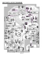
LED SCHEMATIC DIAGRAM:
SG7• 12
LED PARTS LAYOUT DIAGRAM:
SG7• 13
BUILDING THE LED SPEED READOUT UNIT:
There are FOUR basic considerations in assembling this PC board:
1. Good, basic PC board construction technique.
2. Avoiding or repairing "solder bridges" on 110 different IC or LED display
solder points.
3. A smooth fit of the PC board into its custom-designed case, which requires
observing assembly directions and understanding the design of the
completed unit. Mostly, this calls for the horizontal installation of electrolytic
capacitors.
4. Planning for and understanding the need for a large number of "jumper"
wires in this circuit board design.
In general, assembly of this PC board is quite conventional, but we'll show you
special steps for a solid, well-fitting installation of the 12-volt power jack.
We encourage you to follow our suggested order of assembly.
PC BOARD ASSEMBLY:
1. Install J2, the audio monitoring jack. Solder all three points. It's easy and
a good start.
2a. Examine J1, the 3-conductor jack for interconnection with the
microwave oscillator or "radar gun" unit of this project. The little plastic
"legs" on the bottom of the jack should be removed, which is easy with wire
nippers or even an emery board. We suggest using a touch of glue on the
underside of the smoothed-out jack body. The purpose of this extra TLC is
to make J2 as rugged as possible for repeated plugging in/out.
2b. Install 3-conductor jack J1 per step 2a.
3. Installation of ICs or IC sockets. Using good technique, the 6 ICs can be
safely and easily soldered directly to the PC board. If you prefer to use
sockets, you will need three 14-pin sockets. Sockets need to be treated
with the same careful attention as the ICs themselves, both in soldering
and IC insertion. For all socket or IC installations, press the device in its
holes so that the body is flush against the board. While holding it in place,
slightly bend the pins in the four corners to hold it in place for soldering.
Use good lighting and a very clean solder tip. Take short breaks as needed
so that the quality of your work remains consistent and solder bridges are
avoided.
IN THE FOLLOWING STEPS, BE SURE THAT THE NOTCHED, DOTTED OR
BANDED END OF EACH IC IS ORIENTED AS SHOWN ON THE PC
DRAWING!!!
SG7• 14
Step 1: Install U1, 14-pin IC, type LM324.
Step 2: Install U2, 14-pin IC, type MC14093 (or CD4093).
Step 3: Install U3, 14-pin IC, type 4011.
Step 4: Install U4, 16-pin IC, type 4518.
Step 5: Install U5, 16-pin IC, type 4511.
Step 6: Install U6, 16-pin IC, type 4511.
IN THE FOLLOWING STEPS, BE SURE THAT THE ORIENTATION DOTS ON
THE LED DISPLAYS ARE POSITIONED AS SHOWN ON THE PC BOARD
DRAWING!!!
Step 7: Install U7, 7-segment LED display.
Step 8: Install U8, 7-segment LED display.
The installation of U5 through U8 clarifies the locations of 15 of the 17 bare
jumper wires to be installed. Be sure to save all the excess wire trimmed from
resistors and capacitors. The jumpers will be installed toward the end of the
assembly process when it is most likely you will have plenty of wire.
4. Install R1, 47K ohm resistor [yellow-violet-orange].
5. Install R2, 47K ohm resistor [yellow-violet-orange].
6a. When installing C2, 100 to 220µF, remember that ALL of the electrolytic
capacitors are to be installed on their sides as shown on the PC board
drawing. Keep the exposed wires as short as possible and observe correct
polarity.
6b. Install C2, 100 to 220µF electrolytic capacitor, observe correct polarity.
7. Install C1, .005 or .0047µF disc capacitor (marked .005, .0047, 502 or
472).
8. Install R3, 47K ohm resistor [yellow-violet-orange].
9. Install R4, 47K ohm resistor [yellow-violet-orange].
10. Install C3, .001µF disc capacitor (marked .001 or 102).
11. Install C5, 2200pF disc capacitor (marked .0022, 2200 or 222).
12. Install C7, .05 or .047µF disc capacitor (marked .05, .047, 503 or 473).
13. Install C8, .05 or .047µF disc capacitor (marked .05 or .047 or 503 or
473). If C7 and C8 are large size (greater than the size of a "dime") disc
capacitors, they should be mounted on the solder side of the PC board to
ensure a good fit of the case.
SG7• 15
14. Install R6, 1 megohm resistor [brown-black-green].
15. Install R8, 22K ohm resistor [red-red-orange].
16. Install R27, 220 ohm resistor [red-red-brown].
17. Install R9, 22K ohm resistor [red-red-orange].
18a. Examine the two small potentiometers. While they may be identical in
appearance, one is stamped 2.2K (R10, Sensitivity Control), and the other
is 10K (Calibration Control). Both of these controls are mounted on the
solder-side of the board so that adjustments can be made without
completely disassembling the LED Speed Readout unit.
18b. Install R10, 2.2K potentiometer per step 18a.
19. Between J1 and J2, install C21, 10µF electrolytic capacitor, observe
polarity.
20. Install R26, 4.7K ohm resistor [yellow-violet-red].
21. Install R25, 4.7K ohm resistor [yellow-violet-red].
22. Install R7, 100K ohm resistor [brown-black-yellow].
23. Install C12, 100 to 220µF electrolytic capacitor. Again, be certain to
install this and other electrolytic capacitors horizontally.
24. Install C4, .01µF disk capacitor (marked .01 or 103 or 10nF).
25. Install R5, 10K ohm resistor [brown-black-orange].
26. Install R11, 100 ohm resistor [brown-black-brown].
27. Install C6, 10µF electrolytic capacitor.
28. Install C9, 10µF electrolytic capacitor.
29. Install R16, 100K [brown-black-yellow].
30. Install R14, 10K [brown-black-orange].
31. Install R15, 100K [brown-black-yellow].
32. Install C13, .01µF disc capacitor (marked 103 or .01 or 10nF).
33. Install C17, .01µF disc capacitor.
34. Install R28, 100K ohm resistor [brown-black-yellow].
35. Install R22, 10K ohms on the solder side. This is the other small
potentiometer for Calibration Control.
36. Install R21, 10K ohm resistor [brown-black-orange].
37a. The correct value for electrolytic capacitor C20 is determined by the
manufacturing code of the 4093-type IC chip actually supplied in your kit.
Your kit may include either of two capacitors:
SG7• 16
•
If U2 is marked "CD4093", then C20 is 22µF electrolytic capacitor.
•
If U2 is marked "MC14093", the C20 is 33µF electrolytic capacitor.
37b. Install the correct value for C20 per 37a, observe correct polarity.
PROGRESS SUMMARY:
By now, you have installed the majority of the individual components for the
LED Speed Readout Unit. As you can see on the PC board drawings,
installation of a large number of jumper wires is required, and their correct
connections are seen most clearly in relation to the ICs. Jumpers act as
miniature "electronic bridges" that carry signals over PC board traces. You can
make a jumper from a scrap, clipped off component lead wire shaped into a
small loop.
JUMPER WIRES: Mark off each one as installed, while proceeding with the
remaining assembly steps:
Jumper Wire No. 1
Jumper Wire No. 10
Jumper Wire No. 2
Jumper Wire No. 11
Jumper Wire No. 3
Jumper Wire No. 12
Jumper Wire No. 4
Jumper Wire No. 13
Jumper Wire No. 5
Jumper Wire No. 14
Jumper Wire No. 6
Jumper Wire No. 15
Jumper Wire No. 7
Jumper Wire No. 16
Jumper Wire No. 8
Jumper Wire No. 17
Jumper Wire No. 9
ALL JUMPER WIRES INSTALLED!!
38. Install C14, 10µF electrolytic capacitor, observe polarity.
39. Install R23, 220 ohm resistor [red-red-brown].
SG7• 17
40. Install R24, 220 ohm resistor [red-red-brown].
41. Install C19, .01µF disc capacitor (marked .01 or 103 or 10nF).
42. Install C16, 100pF disc capacitor (marked 100 or 101).
43. Install R17, 10K ohm resistor [brown-black-orange].
44. Install R20, 47K ohm resistor [yellow-violet-orange].
45. Install C15, .01µF disc capacitor (marked .01 or 103 or 10nF).
46. Install R18, 47K ohm resistor [yellow-violet-orange].
47. Install D1, the small 1N4148 diode. Orient the banded (cathode) end
Correctly as shown in the drawings.
48. Install C18, .01µF disc capacitor (marked .01 or 103 or 10nF).
49. Install R12, 3.3K ohm resistor [orange-orange-red].
50. Install R19, 100K ohm resistor [brown-black-yellow].
51. Install C10, 10µF electrolytic, observe polarity.
52. Install R13, 47K ohm resistor [yellow-violet-orange].
53. Install C11, .001µF (marked .001 or 102). .
54. Install Q1, 2N3904 transistor with the flat side oriented as shown on the
PC board drawing. Press the transistor firmly into its holes, keeping wire
leads as short as possible.
55. Install D2, type 1N4002 or 4002, the larger, remaining diode. Be sure
that the banded (cathode) end is oriented correctly.
56a. Review the Jumper Wire list and the Parts layout diagram, making
sure that all jumpers are installed correctly.
56b. Verify that all IC chips or sockets (U1- U8) are installed correctly.
57a. Install power jack, J3. This jack is surface-soldered between the
ground foil and the PC board pad area connected to Jumper 17. The side
of the jack with the middle (unused) connector faces away from the solder
side of the board, leaving the smooth side nearly flush with the component
SOLDER
SG7• 18
side. Do a trial positioning in order to understand how the jack is
connected. Notice that the edges of the two jack lugs will be perpendicular
to the PC board surface.
57b. The PC board areas to which the two outer jack lugs are to be
soldered may be covered with a green coating called solder mask. If so,
use a knife blade to gently scrape away the mask from the area shown
down to bare shiny copper.
57c. "Tin" both copper areas with solder. A moderate buildup of solder is
OK and will make installation of the jack easier. The two jack lugs may be
tinned as well.
57d. After one more "fitting" by eye, solder ONE of the jack lugs in place.
Re-melt and adjust as needed to get a good square positioning.
57e. With the jack looking good and secured at one lug, do a good job of
soldering the other connection. Then, touch up the first connection if
needed. Absolutely excellent solder joints are needed since these
connections are the mechanical strength of J3's installation.
Wiring of the SG7 Speed Readout Unit PC board is now complete, but PLEASE
follow our direction steps for installing this board in the custom case and panel
supplied.
ASSEMBLING THE CASE AND PC BOARD:
1. Mount the small red plastic lens filter. The red lens should neatly cover
the LED window and is secured with a piece of tape to the inside of the
case shell. Be sure the tape does not cover any part of the window area.
We do not supply the tape, simply use a bit of scotch tape or electrical tape.
2. BEFORE peeling the backing off from the front panel decal, lay it in place
to get an idea of the best positioning.
3. After removing the backing, lay one of the long edges in place on the
case, making sure that the fit is straight and square. Then lay it down
completely and gently smooth it into place. Do this carefully, since a second
try would be difficult.
4. Select the four 4-40 screws and four standoffs. These screws go through
the front panel decal and into the standoffs. Make neat starter holes
through the decal using a sharp point such as a nail and mount the standoff
spacers to the case front.
5. Mount the PC board to the threaded spacers, using the remaining four
machine screws. The board should rest evenly on the spacers with no
component pressing hard against the case.
6. Set aside the back shell and case screws until after initial tests and
adjustments are completed.Note: If you wish extra protection for the front
SG7• 19
panel decal, it may be sprayed with a fast-drying clear acrylic or
urethane finish. Be sure to mask off the red lens window to avoid
covering it with spray.
BUILDING THE SG7 MICROWAVE OSCILLATOR:
Before beginning, study the PC board layout diagram on the next page.
Some parts are mounted completely on the top side while others have one
lead soldered to a strip on top and another passing through a hole for
soldering on the solid tinned side. Here are some general suggestions to
help assembly go as smoothly as possible:
1. Follow our suggested order of assembly. These steps are given to help
you mount components as smoothly and neatly as possible.
2. A surface-mounted part can be secured most easily if the area to which it
is to be soldered has been pre-tinned with enough solder to form a good
connection. Otherwise, you will find yourself needing three hands in some
cases.
3. Before soldering, it is best to do a careful test-fitting of the part, gently
bending each lead for a neat, precise fit, and then PRE-TRIM the leads
to their desired length. Your work will be much simpler, easier and neater
if you follow this procedure. (However, the connections made on the solid
tinned side should be trimmed after soldering.)
4. In all soldering to the solid tinned side of the board, use enough heat to let
the solder flow freely to form a shiny and solid connection.
5. For easy identification, some of the tinned traces on the top of the board
are identified by a double letter such as "AA".
6. Notice that C7, a .001µF SMT (Surface Mount Technology) chip
capacitor, has been pre-installed at the factory. Be careful when soldering
not to damage or dislodge it.
The first few steps are explained in greater detail to help you develop a
good technique for proceeding more quickly after making a good beginning.
SG7• 20
MICROWAVE OSCILLATOR PARTS LAYOUT:
1.1" LO NG
AN TEN N A
CO NNEC TO R M O UNTED O N
GRO UND PL ANE SIDE
SG7• 21
1a. Disc capacitors C1 and C2, .01µF (marked .01 or 103 or 10nF) are
installed as a single operation. Notice that each has one lead going through
the board and another to be soldered to a trace on the top. Also notice that
the ground pin of the signal jack will be soldered to AA. Therefore the wire
leads of C1 and C2 provide the ONLY connection between AA and the
main ground plane and must be soldered on BOTH sides of the board.
1b. C1 and C2 are prepared as follows: Leave one lead wire straight, and
bend the other lead to a right angle from its body. Do the same for the other
capacitor. Select one capacitor and insert the straight lead through its hole
on AA then trim the bent lead so that it sits in perfect position. Make sure
just enough of the straight lead is exposed to permit a solid solder
connection to AA. Solder all points in whichever order seems easiest.
1c. Install the other .01µF disc capacitor as explained above.
2a. Notice that C3, the 220µF electrolytic capacitor, also has one wire
above (+) and the other (-) below. This capacitor and the other two
electrolytic capacitors are installed so that their sides lay flat on the board.
In addition, notice that holes are provided for each capacitor position so
that you can solder hold-down wires for mechanical stability. Whether you
install the hold down wires first, or solder the capacitor connections is up to
you. Do whatever is easiest, making sure you watch out for polarity and
that exposed wires are no longer than needed. If you prefer, these
capacitors may also be held in place with a small drop of adhesive, such as
silicone cement. It is important that they not vibrate during operation.
2b. Install C3, 220µF electrolytic capacitor, per 2a above.
3. Install C4, 1µF electrolytic in the same manner as above. This is the first
component for which both connections are made on the top side of the
board.
4. Install C5, 1µF electrolytic the same way.
5. Install R1, 10K ohms [brown-black-orange]. Remember that small parts
are easier to surface-solder if the connections are pre-tinned and the wire
leads are pre-formed and trimmed.
6. Install C6, .01µF Disc capacitor (marked .01 or 103 or 10nF).
7. Install R2, 1 megohm [brown-black-green].
SG7• 22
8. Install D1, the 1N4148 diode. Be sure not to confuse it with the special
1SS99 hot carrier diode which is smaller and has black and blue color
bands. Be sure that the banded (cathode) end is oriented correctly.
9. Install Q1, 2N3904 transistor. The flat side must face D1, and the lead
wires of the transistor must be soldered on BOTH sides of the PC board.
Pre-form the leads and it will sit in position very nicely for soldering.
10. Install R3, 1K ohms [brown-black-red].
11. Install a jumper wire from BB to CC, taking care that it bridges PC
board trace DD without touching it. Remember to pre-tin BB and CC and to
handle the jumper with tweezers or pliers.
12a. Before installing the next 4 parts, study the arrangement of R4,R5, Q2
and R6. Install these parts in the order suggested.
12b. Install R4, 100 ohms [brown-black-brown].
12c. Install R5, 100 ohms [brown-black-brown].
13a. Before installing Q2, the NE021 transistor, make sure that all three
connection points are pre-tinned and that there is sufficient solder tinning
for easy installation of R6 after finishing Q2. Use tweezers to hold Q2
neatly in place for soldering.
13b. Install Q2 per 13a. above.
14. Install R6, 10K ohms [brown-black-orange].
15a. Notice the pairs of holes at points EE and FF. At both points, a small
U-shaped jumper is installed and soldered on BOTH sides of the board.
(Folks like me who are not microwave geniuses might wonder why the PC
board trace for the antenna is shorted out straight to ground. The answer is
that this circuit trace as well as the adjacent strips for the base and collector
of Q2 are actual circuit components! Notice the schematic).
15b. Using bare scrap wire, install the jumper at EE.
15c. Install the jumper at FF. Be quick and CAREFUL so as not to damage
C7, the factory-installed SMT chip capacitor.
16a. A length of tinned wire is supplied with your kit and is soldered to point
GG and trimmed to form the 2600MHz antenna. In soldering, concentrate
on keeping the wire straight and centered on the tinned strip. About 1/2inch of the wire should be soldered solidly to the strip.
16b. Solder the antenna wire per 16a.
16c. Trim the antenna lead wire to 1.1 inches from the edge of the board.
Measure carefully and cut the wire as required.
17a. Careful installation of D2, 1SS99 (marked with black and blue bands)
SG7• 23
is important for several reasons. If it is damaged, your project will be on
hold until you can get a replacement from us. Also, lead wires MUST be
kept as short as possible - and its cathode end is soldered very near the
SMT chip capacitor. Its glass body is very fragile, so be careful!
17b. After considering the concerns in step 17a., carefully install diode D2,
making sure the banded (cathode) end is toward C7.
CONGRATULATIONS! You have completed construction of a 2.6GHz.
microstrip oscillator. It is ready for its shielding cover, but - DO NOT install the
cover until completing several voltage tests explained below.
The following tests require completion of the SG7 Speed Readout circuit board,
correct preparation of the 2-conductor shielded cable set, and a reliable 12 volt,
200 ma minimum power source:
1. First, make sure that the voltage to the Speed Readout unit is a healthy
12-13 volts, not "10 or 11 volts or so". You will NOT get acceptable
readings with a lower supply voltage, and you cannot do anything else
useful with this PC board until it is enclosed and properly soldered to the
antenna housing.Verify the following voltages on the microwave oscillator
board:
2. Strip DD: 8 volts DC
3. Collector of Q1: about 3.7 volts
4. Collector of Q2: about 6 volts (5.5 to 6.5 is OK)
5. Base of Q2: 2.3 to 2.7 volts
Once you verify the above voltage readings, you can proceed to the section on
installing the shielding cover. Before doing so, take one last and critical look at
the quality of all solder points. And be VERY sure that there are no bits of wire
or solder tucked under a resistor or capacitor.
FORMING AND INSTALLING THE MICROWAVE OSCILLATOR
SHIELD:
If you are used to making your own metal chassis projects, just what to do with
the pre-cut oscillator cover will be obvious. Just get your bends going right from
the start - or you will have to reverse them and risk weakening and distorting
the bends. If you have never done something like this ever before, fear not. It's
an easy process and even shows the basics of how a sheet-metal "brake"
works. Such a metal brake is an even-pressure folding machine, whether used
to make electronic chassis or heating/air conditioning ductwork!
The idea is to fold the 4 "flaps" to a clean 90-degree angle from the "top" so that
the finished assembly makes a snug-fitting cover for the SG7B Microstrip
Oscillator Board. The cover goes over the component side of the PC board, so
that the shiny ground-plane side of the board and cover form a neat box, with
SG7• 24
the 1.1" antenna extending neatly through the pre-cut notch.
While the first one or two bends can be made using a small hobby vise, the
process will show you why you need some kind of rigid straight edge to
complete the job.
IMPORTANT: While the metal is easy to bend and you are strong and healthy,
your two thumbs are NOT a smooth-metal bending tool. A pair of solid, even
forming edges are required for a straight bend. One edge remains stationary,
and the other edge moves an entire flap evenly into correct position.
Because the shield needs to be soldered securely to the outer side of the PC
board, it is useful to bend each flap slightly more in toward the center, so that
the four sides formed by these flaps can grip the PC board in position for easy
soldering.
MOUNTING THE MICROSTRIP OSCILLATOR:
Performing this operation correctly is absolutely essential to achieving
specified performance and range of the Ramsey SG7 Personal Speed Radar.
Please follow our directions!
1. Drill a 1/4" hole (no larger) at a distance 1-7/8" from the closed end of the
can. Most coffee cans have indented rings, 1-7/8" is the 2nd ring from the
bottom of the can.
2. If there is paint on the can, whether it is your’s or the coffee company's,
it must be removed from the 1" X 2" area to which the oscillator assembly
will be soldered.
3. Use emery paper and/or a stiff wire brush to clean thoroughly the area to
be soldered.
4. Tin the area to be soldered. An ordinary soldering pencil will work fine for
both tinning and soldering work. It can also be helpful to pre-tin one or two
of the points on the oscillator assembly that will be soldered to the can.
5. With the oscillator assembly positioned in a straight line (parallel with the
sides of the can), and the antenna centered in the 1/4" hole, solder them
together at two points to hold the oscillator assembly in place.
SG7• 25
6. Make a final check for straightness and antenna positioning.
7. Solder all 4 sides of the oscillator assembly to the can. A solid solder
seam is as important for range as it is for mechanical strength. The solder
must run fully along all edges where the oscillator box touches the can.
Flow enough solder to fill in any can ribbing under the oscillator box.
8. Do not paint the oscillator assembly until you are positive that your SG7
is functioning as specified. Otherwise, any desoldering required will be
needlessly complicated and messy.
MICROWAVE OSCILLATOR SCHEMATIC DIAGRAM:
SG7• 26
MAKING THE METAL RADAR ANTENNA HOUSING:
"What??? I paid all this money for an electronics kit and I'm now expected to
solder some tin cans?"
Leaving this particular phase of building Speedy to your own craftsmanship is
the only possible way we can bring you this kit project so inexpensively. How
else, aside from using the common metal can, will we get a perfectly round
metal tube with one end completely closed in? Of course, if precision sheet
metal work is your craft or hobby, you can make a housing to suit your own
standards which would be beyond what is possible for most other people.
The standard SG7 design is based on using two 1-pound (or 13 oz.) coffee
cans. But, now that coffee is being packaged in just about everything else
except the classic 1-pound can, we have compiled the following list of
alternative can combinations.
DESCRIPTION
(All diameters = 3.875"):
TOTAL LENGTH
1
1-pound ("13 oz") coffee can
11"
2
40-ounce food cans
13"
1 ea.
coffee can and 40-oz. can
12"
1 ea.
40 oz. food can and 28-oz food can
11"
The can combination that has received long-term testing in a number of
different units is the original coffee can combination. A rule of thumb is that
the longer the completed can assembly, the sharper the focus of the radar
gun, meaning that it has to be pointed more directly. An advantage of the 40
oz. and 28 oz. food cans is that they are generally bare metal with easily
removed paper labels, making soldering and finishing that much easier. The
40 oz. cans are used typically for precooked pasta and bean products, while
the 28 oz. cans are used for fruits and vegetables. Please use one of the can
combinations recommended above, because we have no data to support the
feasibility of other size cans.
SOLDERING THE CANS TOGETHER:
A neat seam around the joint of the two metal cans will contribute to the good
looks of your finished Speedy. A solid seam is needed for proper performance
and range. These are the steps for making a good solder seam:
1. Clean both can rims thoroughly with a wire brush or other abrasive tool.
Do this VERY THOROUGHLY!
2. Carefully remove any small dents (or get another can).
SG7• 27
3. Line up the main seams of both cans in a straight line. (This is only
for a better-looking job.)
4. With the two cans perfectly joined together, use several strips of
masking or electrical tape to hold the rims steady.
5. In the centers of the exposed non-taped areas, make good, solid
solder joints at least a half inch long.
6. Remove all tape and re-clean the areas to which the tape had
adhered.
7. Patiently solder a solid seam around the entire perimeter of the joined
can rims.
8. As you work, believe that it can be done and that it should be done!
Yes, it CAN be done!
To keep it from being a frustrating ordeal, you may get some practice on two
other un-needed cans before working on the SG7 itself. However, be sure to
do the preparatory cleaning steps on the test cans just as thoroughly, or the
solder will just roll up into little balls and laugh at you. (Also, you find that
solder can adhere to the thinner can surface much more easily than to the
reinforced rims!) The idea is to discover just how much heat you need and
how slowly or quickly the soldering tip can be moved. Again, BE SURE to
make the can rims clean and shiny before soldering.
A miniature hobby torch with a pin-point flame is an ideal tool. A standard
propane torch seems to be entirely TOO MUCH even at its lowest setting. A
soldering gun should work well, but I was getting better results with a 25watt pencil iron than from a 75-watt gun. I also tried one of those portable
butane soldering pens, but I would not recommend buying that tool just for
this job.
A second soldering pencil can be used by a helper to intensify the heating of
the can rims. (If you would like to be rebellious for once on an electronics
project, and know that you can do a better job with solid or acid core solder,
paste and torch, that's just fine - on THIS part of the SG7 project only! And,
if you're already good at light welding-brazing, or know someone who is,
then go for it!)
After the cans are soldered together, any rough spots in the soldered seam
can be smoothed out, and the unit can then be painted or covered with
contact paper. We remind you again not to do ANY painting around the
oscillator assembly until correct operation is verified. You may wish to add a
handle or tripod mount. These can be glued to the outside of the can, but a
couple of small screwheads protruding within the can assembly will not
disturb SG7 performance. The plastic lid of a coffee can will fit the open end
of any of our recommended can combinations and will keep dirt and
moisture out of the inside.
SG7• 28
TESTING AND CALIBRATION:
1. Connect an earphone to J2, using a subminiature plug or adapter.
2. Connect the counter and oscillator units together with the shielded 3conductor cable already assembled.
3. While listening to the earphone, plug in the 12 volts DC cord. The LED
displays should light right away. After a few seconds, you should hear a
steady AC buzz in the earphone. Next, if you wave your hand in front of
the open end of the antenna "can", you should hear a rapid series of
clicks. The faster you move your hand toward the unit, the faster the
rate of the clicks. You are hearing the Doppler effect at work.
4. While still indoors, point the unit toward a fluorescent light fixture and
adjust the Calibration pot for an LED reading of 18. This provides a
calibration of the speed counter.
5. It is normal for resistors R23 and R24 to be fairly warm to the touch.
6. The correct Doppler shift at the operating frequency of the SG7 is 7.76
Hz per mile-an-hour.
7. Due to the extreme high gain and sensitivity of the SG7, do remember
that all indoor tests and usages will be affected by powerful AC 60 Hz
power mains, lines and light flux!
SG7• 29
FINAL CALIBRATION:
To put it simply, the SG7 is calibrated by adjusting the control while pointing
the antenna unit at a vehicle traveling at a steady, known speed. Obviously,
the accuracy of the radar unit depends on the steadiness of the test drive
and the accuracy of the vehicle's speedometer. To verify speedometer
accuracy, use a stopwatch to time how long it takes the vehicle to travel a
given distance and carry out the appropriate calculations.
If the speedometer accuracy seems questionable, and no other test vehicle
is easily available, simply set up a safe test-run course to clock the car for a
certain speed. For a test speed of 30 mph., the car would cover half of 5280
feet in a minute, (that is 2640 feet in 60 seconds) which would result in
these test runs which are reasonable in length and sufficient time for
accuracy:
2640/6 = 440 feet in 10.0 seconds
2640/10 = 264 feet in 6.0 seconds
2640/12 = 220 feet in 5.0 seconds
Believe the time-distance results rather than the speedometer. If the car
consistently covers 440 feet in 10.0 seconds with the speedometer reading
27 mph, then have the driver drive at an indicated 27 mph as you calibrate
the SG7 for 30 mph. You can use any test speed which is safe for the
purpose, and the same procedure is used for kilometer/hour calibrations as
well. A bicyclist maintaining an accurate speed in the 15-20 mph range can
also do the job. If you are curious as to how radar guns are otherwise
calibrated, the procedure requires the use of a test device able to generate
a "false target"; simply a microwave signal of a known frequency that is
different from the fundamental frequency of the radar gun being calibrated.
Differences between the radar gun's frequency and the standard test
frequencies of the calibrating device are marked as test standard speeds
(25,35,55 mph, etc). A very informative construction article for exactly such
a test device was published in the Electronics Experimenters Handbook, an
annual publication of Radio-Electronics Magazine (Gernsback Pub., Inc.,
500-B Bi- County Blvd. Farmingdale, NY 11735)
Gain control adjustment:
After calibration, point the unit up into the air and adjust the gain control
clockwise until you just start to see a reading of 3 or 4. This will set the gain
at just below the maximum unstable point and give the best range. This
adjustment is somewhat critical, so take your time in doing it.
SG7• 30
TROUBLESHOOTING HINTS
1. Instructions are provided for checking voltages on the microstrip oscillator
board before soldering the cover on.
2. If operation is erratic, check the cable assembly, and be sure that you
followed the instructions for trimming away the plastic legs on BOTH 3conductor jacks. If this is not done, reliable solder connections are difficult
to make.
3. If you don't hear anything in the earphone, check the earphone itself, the
plug or adapter for J2, the orientation of the NPN transistor and the
polarity of C10 and C12.
4. If you experience other problems in the counter display unit, please
recheck the following in this order:
a. Correct orientation of ICs and 7- segment displays.
b. If sockets were used, check for bent IC pins.
c. Correct polarity of all electrolytic capacitors.
d. Correct orientation of D1 and D2.
e. Possibility of solder bridges, especially at ICs.
f. Forgotten solder joints.
g. Correct resistor values.
h. All jumper wires installed.
5. Common causes of major trouble:
a. Antenna shorted to can.
b. Defective 3-conductor cable assembly.
c. Reverse polarity on power cord.
d. Solder bridges.
e. Reversed diodes (BOTH PC boards).
6. If you experience poor range, check:
a. Correct length of antenna wire probe
b. SHORT lead length on the 1SS99 diode
c. Proper adjustment of the gain control pot
d. Clean, solid 12 volt power source
e. Be sure outside sources are not interfering with the SG7
SG7• 31
MODIFICATIONS:
We are always interested in any customer reports and suggestions on
adaptions of the basic SG7 design. We do not recommend any circuit
modifications and ask that you remember that modifications make your kit
ineligible for factory repair. Our technicians are not able to get into telephone
discussions of possible modification ideas, but we're always glad to reply by
fax or mail to a few clearly-stated "yes-no" questions.
SG7 STATISTICS AND SPECIFICATIONS:
RANGE: Properly constructed, the SG7's is a mile, depending on terrain,
target size and obstruction.
ACCURACY: 1 mph from 10 to 99 mph.
TARGET LOCK TIME: For an accurate reading, the SG7 must be pointed at
the oncoming target for at least 2/7 of a second.
COUNTER UPDATE TIME: 1/7 second.
POWER SUPPLY: 12-14 Volts DC at 150 ma.
OPTIONAL CALIBRATIONS: Resistor R21 may be changed to permit any of
the following distance/combinations:
R21 = 10K
R21 = 4.7K
R21 = 4.7K
R21 = 15K
LED Readout = Miles per hour (standard)
LED Readout = Kilometers per hour or:
LED Readout = Feet per second
LED Readout = Meters per second.
OUTPUT SIGNAL FREQUENCY: The frequency of the output signal fed
from the radar gun unit to the counter-readout unit is computed by this
equation:
fd = 2.6 X 10^9 (2v/c) where:
v= target speed in meters-per-second
c = 3 X 10⁸ meters-per-second
fd = Doppler shift frequency.
MORE SIMPLY: 1 MPH = 7.76 Hertz of Doppler shift frequency
THEREFORE: MPH = Total Doppler shift in Hz divided by 7.76.
IMPORTANT MEASUREMENTS:
• Antenna length =1.1 inch
• Antenna distance from back of can = 1.875 inch
SG7• 32
USING THE SG7:
The SG7 Personal Speed Radar is suitable for any application which comes
within its specified range and accuracy. It was designed to be fun and
educational and we assume that you will find your own uses for it, whether
for sporting events, as a science fair project, scout troop project, or school/
neighborhood volunteer safety patrols.
Remember that the purpose of ANY speed radar is to provide a speed
indication that falls within reasonable tolerances. If absolute accuracy is
required, there is no substitute for careful distance/time calculations using a
stop watch on an exactly-measured course. If your SG7 is used in
conjunction with any kind of volunteer traffic safety project, it is up to the
users to cooperate with local police and other authorities and to be capable
of testifying to the purpose and accuracy of the unit for a given situation.
While it would be silly to make a big fuss over a reading of 17 in a 15 mph
school zone, a reading of 30 or 35 would be a cause for concern, as would a
reading of 50 in a 35 mph zone.
NOTE: Use caution and courtesy when clocking vehicles for any reason. Not
only do you want to avoid getting run over, it can be very dangerous to
startle an oncoming motorist. It is always best to use your SG7 as
inconspicuously as possible.
Finally, who says you have to be standing still and pointing at a moving
target? What would you see if you were sitting in the bow of a boat with the
SG7 pointed at a fixed object within its range? Or had it mounted on the
handlebars of a racing bike? Enjoy your Speedy Personal Radar!
If you enjoyed building this Ramsey kit, there are a lot more in our catalog call or write for your copy!
SG7• 33
The Ramsey Kit Warranty
Please read carefully BEFORE calling or writing in about your
kit. Most problems can be solved without contacting the
factory.
Notice that this is not a "fine print" warranty. We want you to understand
your rights and ours too! All Ramsey kits will work if assembled properly.
The very fact that your kit includes this new manual is your assurance
that a team of knowledgeable people have field-tested several "copies"
of this kit straight from the Ramsey Inventory. If you need help, please
read through your manual carefully. All information required to properly
build and test your kit is contained within the pages!
1. DEFECTIVE PARTS: It's always easy to blame a part for a problem
in your kit, Before you conclude that a part may be bad, thoroughly
check your work. Today's semiconductors and passive components
have reached incredibly high reliability levels, and it’s sad to say that our
human construction skills have not! But on rare occasions a sour
component can slip through. All our kit parts carry the Ramsey
Electronics Warranty that they are free from defects for a full ninety (90)
days from the date of purchase. Defective parts will be replaced
promptly at our expense. If you suspect any part to be defective, please
mail it to our factory for testing and replacement. Please send only the
defective part(s), not the entire kit. The part(s) MUST be returned to us
in suitable condition for testing. Please be aware that testing can usually
determine if the part was truly defective or damaged by assembly or
usage. Don't be afraid of telling us that you 'blew-it', we're all human and
in most cases, replacement parts are very reasonably priced.
2. MISSING PARTS: Before assuming a part value is incorrect, check
the parts listing carefully to see if it is a critical value such as a specific
coil or IC, or whether a RANGE of values is suitable (such as "100 to
500 µF"). Often times, common sense will solve a mysterious missing
part problem. If you're missing five 10K ohm resistors and received five
extra 1K resistors, you can pretty much be assured that the '1K ohm'
resistors are actually the 'missing' 10 K parts ("Hum-m-m, I guess the
'red' band really does look orange!") Ramsey Electronics project kits are
packed with pride in the USA. If you believe we packed an incorrect part
or omitted a part clearly indicated in your assembly manual as supplied
with the basic kit by Ramsey, please write or call us with information on
the part you need and proof of kit purchase.
SG7• 34
3. FACTORY REPAIR OF ASSEMBLED KITS:
To qualify for Ramsey Electronics factory repair, kits MUST:
1. NOT be assembled with acid core solder or flux.
2. NOT be modified in any manner.
3. BE returned in fully-assembled form, not partially assembled.
4. BE accompanied by the proper repair fee. No repair will be
undertaken until we have received the MINIMUM repair fee (1
hour labor) of $50.00, or authorization to charge it to your credit
card account.
5. INCLUDE a description of the problem and legible return address. DO
NOT send a separate letter; include all correspondence with the
unit. Please do not include your own hardware such as nonRamsey cabinets, knobs, cables, external battery packs and the
like. Ramsey Electronics, Inc., reserves the right to refuse repair
on ANY item in which we find excessive problems or damage due
to construction methods. To assist customers in such situations,
Ramsey Electronics, Inc., reserves the right to solve their needs
on a case-by-case basis.
The repair is $50.00 per hour, regardless of the cost of the kit. Please
understand that our technicians are not volunteers and that set-up,
testing, diagnosis, repair and repacking and paperwork can take nearly
an hour of paid employee time on even a simple kit. Of course, if we find
that a part was defective in manufacture, there will be no charge to
repair your kit (But please realize that our technicians know the
difference between a defective part and parts burned out or damaged
through improper use or assembly).
4. REFUNDS: You are given ten (10) days to examine our products. If
you are not satisfied, you may return your unassembled kit with all the
parts and instructions and proof of purchase to the factory for a full
refund. The return package should be packed securely. Insurance is
recommended. Please do not cause needless delays, read all
information carefully.
SG7• 35
SG7 PERSONAL SPEED RADAR KIT
Quick Reference Page Guide
Introduction to the SG7 ........................ 4
Parts list ............................................... 7
LED schematic diagram ..................... 12
LED unit PC layout ............................. 13
Assembling the LED unit .................... 14
Assembling the microwave unit .......... 20
Microwave unit PC layout ................... 21
Microwave unit PC board ................... 26
Testing and calibration ....................... 29
Troubleshooting hints ......................... 31
SG7 statistics and specs .................... 32
REQUIRED TOOLS
• Soldering Iron Ramsey WLC100
• Thin Rosin Core Solder Ramsey RTS12
• Needle Nose Pliers Ramsey MPP4 or
RTS05
• Small Diagonal Cutters Ramsey RTS04
<OR> Technician’s Tool Kit TK405
ADDITIONAL SUGGESTED ITEMS
• Holder for PC Board/Parts Ramsey HH3
• Desoldering Braid Ramsey RTS08
• Digital Multimeter Ramsey M133
Price: $5.00
Ramsey Publication No. MSG7
Assembly and Instruction manual for:
RAMSEY MODEL NO. SG7
PERSONAL SPEED RADAR KIT
RAMSEY ELECTRONICS, INC.
590 Fishers Station Drive
Victor, New York 14564
Phone (585) 924-4560
Fax (585) 924-4555
www.ramseykits.com
SG7• 36
TOTAL SOLDER
POINTS
300
ESTIMATED
ASSEMBLY TIME
Beginner ........... 8.5 hrs
Intermediate ..... 5.5 hrs
Advanced .......... 4.5 hrs