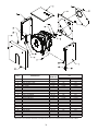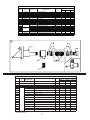
1
D
E S I G N E D
T O
L
E A D
Freeport ODV Series
Oil-Fired Direct Vent Hot Water Boilers
These instructions must be affixed on or adjacent to the boiler.
Models
• ODV-75
• ODV-100
• ODV-125
WARNING: Improper installation, adjustment, alteration,
service or maintenance can cause property damage, injury,
or loss of life. For assistance or additional information
consult a qualified installer or service agency. This boiler
requires a special venting system. Read these instructions
carefully before installing.
Manufacturer of Hydronic Heating Products
P.O. Box 14818 3633 I. Street
Philadelphia, PA 19134
Tel: (215) 535-8900 • Fax: (215) 535-9736 • www.crownboiler.com
TABLE OF CONTENTS
Product Description
1
Specifications
2
Before Installing 3
Locating The Boiler
3
Vent System Installation
4
System Piping
13
Fuel Piping
17
Wiring
18
Start-Up And Checkout
19
Service Notes
20
Maintenance
22
Parts
24
WARNING
FAILURE TO VENT THIS BOILER IN ACCORDANCE WITH THESE INSTRUCTIONS
COULD CAUSE FLUE GAS TO ENTER THE BUILDING RESULTING IN SEVERE
PROPERTY DAMAGE, PERSONAL INJURY, OR DEATH:
• Do not attempt to vent this boiler with galvanized, PVC, or any other vent components
not described in this manual
• Do not obtain combustion air from within the building.
• Do not install a barometric damper or vacuum relief valve in the vent system of this
boiler.
CAUTION
Moisture and ice may form on the surfaces around the vent termination. To prevent
deterioration, surfaces should be in good repair (sealed, painted, etc.).
DANGER
THE VENT SYSTEM SUPPLIED WITH THE ODV IS NOT DESIGNED FOR VENTING
OF FLUE PRODUCTS FROM NATURAL GAS OR PROPANE. DO NOT ATTEMPT TO
CONVERT THE ODV TO EITHER GAS.
I Product Description
The ODV series boiler is a cast iron oil fired boiler designed for use in forced hot water heating
systems. The ODV boiler must be vented using the factory supplied venting system with combustion air taken from outdoors. The ODV uses the same three pass “scotch marine” heat exchanger as
the CT series boiler. The ODV series boiler is ideal for use in installations where a chimney is not
available.
The ODV boiler is not designed for use in gravity or “open” heating systems.
CAUTION
As with any oil appliance, certain adverse conditions can cause this boiler to operate at high
smoke levels. Since the ODV is vented through a wall, this can result in severe soot damage
to the side of the structure around the terminal. To minimize the risk of this:
•
•
•
•
•
•
Follow these installation instructions exactly
Oil burner must be set up by a qualified serviceman using combustion test instruments
Use only the vent components supplied in the ODV vent kit
Combustion air must be supplied from outdoors
Follow the maintenance procedure in this manual
Use only #2 fuel oil meeting ASTM D-396
1
II Specifications
TABLE 1: SPECIFICATIONS
NO.
MODEL SECTIONS
ODV-75
3
ODV-100
3
ODV-125
4
INPUT
Gal/hr)
0.75
1.00
1.25
FIG. 1 DIMENSION "B" (IN.)
D.O.E.
USING
HEATING IBR NET
FIG. 1
STANDARD
OPTIONAL
CAPY.
RATING
DIMENSION
CONNECTION
TEE
(BTU/hr) (BTU/hr) AFUE (%)
"A" (IN.)
91,000
79,000
85.0
32-1/4
24
14
119,000 103,000
83.1
32-1/4
24
14
150,000 130,000
83.5
37-1/4
24
14
Ratings based on #2 fuel oil having a higher heating value of 140,000 BTU/Gal
Net ratings based on a piping and pickup loss allowance of 1.15
Exhaust pipe: 4” I.D. insulated flexible vent pipe.
Maximum exhaust pipe length – 15 ft.
Inlet pipe: 4” I.D. Corrugated Aluminum
Maximum Inlet pipe length – 20 ft
Maximum Wall Thickness in which Terminal is Installed – 12”
2
III Before Installing
1) Safe, reliable operation of this boiler depends upon installation by a professional heating contractor in strict accordance with this manual and the authority having jurisdiction.
•
•
In the absence of an authority having jurisdiction, installation must be in accordance with this manual and Installation of Oil-Burning Equipment (ANSI/NFPA 31).
Where required by the authority having jurisdiction, this installation must conform to the Standard for Controls and Safety Devices for Automatically Fired Boilers (ANSI/ASME CSD-1)
2) Read Section VI to verify that the maximum combustion air and exhaust pipe lengths will not be exceeded in the planned installation. Also verify that the vent terminal can be located in accordance with Section VI. Note: The maximum wall thickness through which the terminal can be installed is 12”.
3) Make sure that the boiler is correctly sized:
•
•
•
•
For heating systems employing convection radiation (baseboard or radiators) use an industry
accepted sizing method such as the I=B=R Heat Loss Calculation Guide (Pub. #H21 or #H22)
published by the Hydronics Institute in Berkely Heights NJ.
For new radiant heating systems refer to the radiant tubing manufacturer’s boiler sizing guidelines.
For systems including a Crown Mega-Stor indirect water heater, size the boiler to have either the DOE Heating Capacity required for the Mega-Stor or the net rating required for the heating system,
whichever results in the larger boiler.
For systems that incorporate other indirect water heaters, refer to the indirect water heater manufac-
turer’s instructions for boiler output requirements.
4) Do not install this boiler at altitudes above 2000ft.
5) Inspect shipment. This boiler is shipped in three pieces:
a) Wire-bound crate with boiler
b) Vent terminal carton – Includes terminal, vent adapters, inlet piping and hardware
c) Vent pipe carton - Includes flexible vent pipe.
IV Locating the Boiler
1) Observe the clearances below. Top, side and rear clearances are from jacket. Front clearance is from burner door.
To Combustible Construction
To Non-Combustible Construction
Front
24
15
Left*
6
2-1/2
Right 6
1
Rear Determined by clearance to Flexible Vent Pipe (below)
Top 24
24
Terminal
0
0
Flexible Vent Pipe
3
0
* 14 inch clearance required to open door.
2) Boiler must be installed on a non-combustible surface.
3) Boiler must be located so that the 15-foot vent pipe supplied with the boiler will reach the planned terminal location. Approximately 1.3 feet of pipe length is used up in making a 90-degree bend
(Fig 11). See Section V for more information on venting requirements.
3
V Vent System Installation
WARNING
• Read the installation instructions carefully and completely before proceeding with the installation of vent system.
• For continued safe operation, the appliance vent system must be inspected and maintained annually by a qualified agency.
Failureto properly maintain the appliance vent system combination can lead to Death, Personal Injury and or Property Damage.
• Plan the vent system layout before installation to avoid the possibility of
accidental contact with concealed wiring or plumbing inside walls.
The ODV boiler is shipped with a complete venting system consisting of the following components:
•
•
•
•
•
•
•
•
•
•
•
FDVS-4 direct vent terminal
Backing plate
15-ft length of insulated 4” FOVP flexible oil vent pipe
4” x 7” appliance adapter
(2) Cover rings
(2) Cover sleeves
Bagged hardware
(4) Inner pipe clamps
20 ft length 4” flexible aluminum air intake pipe
(2) Hose clamps
“Red” high temperature RTV silicone sealant
CAUTION
•
•
•
•
•
•
Do not use vent system components other than those supplied with the boiler
Use only the red RTV sealant provided with this boiler anywhere that this manual
calls for the use of “sealant”
Combustion air must be brought from outside as shown in this manual
Do not install a “vacuum relief” damper
Do not attempt to splice vent piping
Do not put holes in venting
1) LOCATING THE TERMINAL – Observe the following requirements in locating the terminal:
a)
b)
c)
d)
e)
f)
Maximum wall thickness through which terminal can be installed is 12”.
Wall can be combustible or noncombustible.
Bottom of terminal must be at least 12 inches above the normal snowline. If normal snowfall is
negligible, terminal must be at least 12 inches above grade (Fig 2).
Bottom of Terminal must be at least 7 feet above a public walkway (Fig 2).
Locate edge of terminal at least 4 ft horizontally from doors, windows, or gravity air inlets. Do not put terminal under windows which can be opened (Fig 2).
Terminal must be close enough to boiler to be connected to it using the vent components supplied.
4
5
g) Do not locate terminal under decks.
h) It is preferable to install the terminal on the wall that is away from the prevailing wind.
i) Do not put terminal under a soffit or other overhang deeper than 18 inches. Top edge of terminal must be at least 2 ft below soffit or overhang (Fig 3).
j) Position terminal to avoid accidental contact with people or pets.
k) Over time, the area around the terminal may become stained. Locate the terminal on a wall where this is not objectionable.
l) No part of an inside corner should extend into the shaded area shown in Figure 4.
m) Terminal must be positioned so that no other buildings are within the shaded area shown in
Figure 4. Other permanent objects in this area may become stained or otherwise effected by flue gas.
n) The terminal is a potential source of odors. Although the above restrictions will generally prevent infiltration of these odors into the building, care should be taken in positioning the terminal near outdoor areas where people congregate, such as patios. This is particularly true when the boiler is used with an indirect water heater that will cause the boiler to run during warm months.
2) INSTALLING THE FDVS-4 VENT TERMINAL
a)
b)
c)
d)
Remove vent system components from box and inspect for damage. If the carton has been crushed or mutilated, check components very carefully for damage. DO NOT install if any
damage is apparent.
Remove the combustion air tee assembly from the vent terminal. Set the tee aside for later use.
After determining the location of the vent terminal (Figures 2,3 & 4), cut a 7-1/4” square hole in the wall. (Figure 5a) Note: Maximum wall thickness: 12”
Seal the back side of the base plate around the outer pipe of the vent terminal with a bead of standard silicone sealant (not supplied). (Figure 5b) Mount the vent terminal through the wall, keeping the outer pipe centered in the hole. (Figure 5a) Fasten the vent terminal to the outside wall with appropriate fasteners. Seal the edges of the vent terminal base plate to the wall with standard silicone sealant.
CAUTION
Failure to apply this bead of silicone properly can cause flue gas to recirculate into
the air inlet resulting in sooting of the boiler, vent system, and side of the strucure.
e) Mount the backing plate over the outer pipe. Fasten the backing plate to the inside wall with
appropriate fasteners. (Figure 5b)
DO NOT BLOCK the intake or exhaust openings, or the intake access panel on the vent terminal body.
Wood or vinyl siding should be cut so that the unit mounts directly on the wallboard to provide a stable
support. If the siding is greater than 1/2” thick use a spacer plate or board behind the vent terminal
mounting plate. (Figure 5b)
f) If the inside terminal section is not supported by the wall through which it passes, install
additional supports or bracing to rigidize the terminal. Bracing in contact with the co-axial
section of the terminal may be combustible.
6
7
3) INSTALLATION OF THE VENT TERMINAL COMBUSTION AIR TEE (Figure 5c)
a)
b)
c)
Assemble the combustion air tee assembly body to the vent terminal outer pipe, and rotate to the
desired position. Attach the tee assembly body to the vent terminal outer pipe with at least 3 sheet metal screws evenly spaced apart (not included).
Perform step 3c only after installing the flexible oil vent pipe to the inner pipe on the terminal as
outlined in step 6. (Figure 6)
Apply standard silicone sealant (not supplied) to the cover pan around the inner pipe, around the joint between the collar and the tee assembly, and seal or tape the joint from the FDVS terminal to the tee assembly.
8
NOTE: The tee may be rotated into any position so that the collar is in a convenient orientation.
4) APPLIANCE ADAPTER INSTALLATION
a) Apply a bead of red silicone sealant (supplied) to the boiler vent collar approx. 1” from end of collar. (Figure 7a)
b) Remove all oil and grease from the inside of the appliance adapter, and apply a bead of red
silicone sealant to inside of adapter ½” from end (Figure 7a).
c) With a twisting motion, assemble the appliance adapter onto the vent collar.
d) Using a block of wood on the end of the adapter, push the adapter onto the vent collar, using care to avoid damaging the vent collar or the adapter (Figure 7b).
e) Keep the sampling port in the 12 o’clock position and align the prepunched slots in the appliance
adapter to the threaded holes on the vent collar.
f) Secure the appliance adapter to the boiler vent collar with (3) 1/4-20 x 1/2” stainless steel cap screws inserted into the three tapped holes in the appliance collar and tighten. (Figure 6b).
g) Apply red silicone sealant to the end of the adapter and anchoring screws. (Figure 7b).
h) After testing and burner adjustments have been made, apply red silicone sealant to the supplied 3/8” sampling port plug screw and install the screw in the sampling port (Figure 7b).
i) Maintain clearances to combustibles. If the appliance adapter is within 18” of combustible
material, wrap minimum 1-1/2” ceramic insulation (installer-supplied) around the exposed
portion of the appliance adapter.
5) OPTIONAL REDUCING TEE ADAPTER INSTALLATION
a)
b)
c)
An optional reducing tee adapter is available for use in place of the standard appliance adapter (Figure 8a). This reduces the clearance needed from the back of the boiler.
Apply a bead of red silicone sealant (supplied) to appliance collar approx. 1” from end of the boiler vent collar. (Figure 8a)
Remove all oil and grease from the inside of the reducing tee adapter, and apply a bead of red
silicone sealant to inside of adapter ½” from end (Figure 8b).
9
d)
e)
f)
g)
h)
i)
j)
With a twisting motion, assemble the reducing tee adapter onto the boiler vent collar.
Push the adapter onto the vent collar, using care to avoid damaging the appliance collar or the adapter (Figure 8b).
Keep the sampling port in the 12 o’clock position and align the prepunched slots in the
reducing tee adapter to the threaded holes on the vent collar.
Secure the reducing tee adapter to the vent collar with (3) 1/4-20 x 1/2” stainless steel cap screws inserted into the three tapped holes in the vent collar and tighten. (Figure 8b).
Apply red silicone sealant to the end of the adapter and anchoring screws. (Figure 8b).
After testing and burner adjustments have been made, apply red silicone sealant to the
supplied 3/8” sampling port plug screw and install the screw in the sampling port (Figure 8b).
Maintain clearances to combustibles. If the reducing tee adapter is within 18” of combustible
material, wrap minimum 1-1/2” ceramic insulation (installer-supplied) around the exposed
portion of the reducing tee adapter.
10
6) VENT PIPE INSTALLATION
CAUTION
a)
b)
c)
d)
e)
f)
•
•
•
Do not enclose vent pipe in walls or ceilings
If necessary, the vent pipe may be cut to length with a hacksaw or cut off saw. Use safety glasses and other appropriate safety gear when cutting. Make sure that the vent pipe route is finalized and pipe is accurately marked before cutting. Pipe cannot be spliced if accidently cut too short.
Pull outer vent pipe back 1”-2” from inner vent pipe end and remove insulation (Figure 9a).
Slide Cover Sleeve onto end of vent pipe a few inches back from end of outer vent pipe
(Figure 9a).
Slide Cover Ring over stop bead on termination inner pipe or appliance adapter (Figure 9a).
Assemble inner pipe clamp halves using the supplied ¼” bolts and square nuts, and position
inner pipe clamp ¼” from end of inner pipe (Figure 9a).
Remove all oil and grease from end of termination inner pipe or appliance adapter, and apply a bead of red silicone sealant to between the stop bead and retainer bead (Figure 9b).
Apply a thick bead of red silicone sealant to inside of inner vent pipe ½” from the end of pipe, working the sealant into the corrugations (Figure 9b).
11
g)
h)
i)
j)
k)
l)
Push the inner vent pipe onto the termination inner pipe or appliance adapter all the way up to the stop bead.
Tighten the inner pipe clamp bolts until both clamp halves are within 1/8” of each other at each end (Figure 9c).
Slide the cover sleeve and cover ring together to engage the ring in the groove of the sleeve, and tighten the cover sleeve clamp (Figure 9d).
To maintain 3” clearance to combustibles, wrap minimum 1-1/2” thick ceramic insulation
(installer-supplied) around the exposed portion of the termination inner pipe (Figure 9d), and secure with foil tape (installer supplied).
Allow sealant to cure for at least one hour before firing boiler.
Use the same procedure to install vent pipe on Reducing Tee (Figure 9e).
8) AIR INTAKE PIPE INSTALLATION
a) Attach flexible air intake pipe to the terminal and the collar on the burner and secure it with the hose clamps provided.
12
VI System Piping
CAUTION
•
•
•
Operation of this boiler with continuous return temperatures below 120f can cause severe heat exchanger corrosion damage
Operation of this boiler in an system having significant amounts of dissolved oxygen can cause severe heat exchanger corrosion damage
Do not use toxic additives, such as automotive antifreeze, in a hydronic system
Standard Piping
Figure 17 shows typical boiler system connections on a single zone system. Additional information
on hydronic system design may be found in Installation of Residential Hydronic Systems (Pub. #200)
published by the Hydronics Institute in Berkely Heights NJ. The components in this system and their
purposes are as follows:
1)
Relief valve (Required) – The relief valve is factory mounted and must not be moved. The relief valve shipped with the boiler is set to open at 30 psi. This valve may be replaced with one
having a setting of up to the MAWP shown on the boiler rating plate. If the valve is replaced, the replacement must have a relief capacity in excess of the DOE heating capacity for the boiler.
Pipe the discharge of the relief valve to a location where water or steam will not create a hazard or cause
property damage if the valve opens. The end of the discharge pipe must terminate in an unthreaded pipe.
If the relief valve discharge is not piped to a drain it must terminate at least 6 inches above the floor. Do
not run relief valve discharge piping through an area that is prone to freezing. The termination of the
relief valve discharge piping must be in an area where it is not likely to become plugged by debris.
DANGER
•
•
•
•
PIPE RELIEF VALVE DISCHARGE TO A SAFE LOCATION
DO NOT INSTALL A VALVE IN THE RELIEF VALVE DISCHARGE LINE
RELIEF VALVE MUST BE INSTALLED IN BOILER AT LOCATION SHOWN IN FIGURE 17.
DO NOT PLUG RELIEF VALVE DISCHARGE
2) Circulator (Required) – Although the circulator is shipped on the boiler return, it can be installed on the boiler supply. If the circulator is moved to the supply it should be positioned just downstream of the expansion tank as shown in Figure 17.
3) Expansion Tank (Required) – If this boiler is replacing an existing boiler with no other changes in the system, the old expansion tank can generally be reused. If the expansion tank must be replaced, consult the expansion tank manufacturer’s literature for proper sizing.
13
4) Fill Valve (Required) – Either a manual or automatic fill valve may be used. The ideal location for the fill is at the expansion tank.
5) Automatic Air Vent (Required) – At least one automatic air vent is required. Manual vents will usually be required in other parts of the system to remove air during initial fill.
6)
Low Water Cut-Off (Required in some situations) – A low water cut-off is required when the boiler is installed above radiation. In addition, some codes such as ASME CSD-1 require
low water cut-offs. Codes may also require that this low water cut-off have a manual reset
function. The low water cut-off may be a float type or probe type but must be designed for use in a hot-water system. The low water cut-off should be piped into the boiler supply just above the boiler with no intervening valve between it and the boiler.
Use a low water cut-off that breaks the line voltage electrical supply to the boiler.
7)
Manual Reset High Limit (Required by some codes) – This control is required by ASME CSD-1 and some other codes. Install the high limit in the boiler supply piping just beyond the boiler with no intervening valves. Set manual reset high limit as far above the operating limit setting
as possible, but not over 240F. Wire the control to break the line voltage electrical supply to the boiler.
8)
Flow control valve (Required under some conditions) – The flow control valve prevents flow through the system unless the circulator is operating. A flow control valve may be necessary on converted gravity systems to prevent gravity circulation. Flow control valves are also used to prevent “ghost flows” in circulator zone systems through zones that are not calling for heat.
9) Isolation Valves (Optional) – Isolation valves are useful if the boiler must be drained, as they will eliminate having to drain and refill the entire system.
14
Piping for Special Situations
Certain types of heating systems have additional requirements. Some of the more common variations
follow:
1)
Indirect Water Heaters – Figure 18 shows typical indirect water heater piping. Boiler piping is the same as for any two-zone system. Figure 18 shows circulator zoning, which is usually
preferred for indirect water heaters. Size the circulator and indirect water heater piping to obtain the boiler water flow through the indirect water heater called for by the indirect water heater
manufacturer.
2)
Gravity and “Large Water Volume” Systems – The piping shown in Figure 19 will minimize the amount of time that the boiler operates with return temperatures below 120F on these systems. A bypass is installed as shown to divert some supply water directly into the return water. The bypass pipe should be the same size as the supply. The two throttling valves shown are
adjusted so that the return temperature rises above 120F during the first few minutes of opera-
tion. A three-way valve can be substituted for the two throttling valves shown. If the circulator is mounted on the supply, the bypass must be on the discharge side of the circulator.
3) Low Temperature Systems – Some systems, such as radiant tubing systems, require the system water temperature to be limited to a value below the temperature of the water leaving the ODV. These systems also typically have return temperatures well below the 120F minimum.
Figure 20 illustrates the use of a heat exchanger to connect an ODV boiler to this type of system. The heat exchanger will permit the transfer of heat from the boiler water to the low temperature system while holding the system supply and boiler return temperatures within their limits. For this system to work properly the heat exchanger must be properly sized and the correct flow rates are required on either side of the heat exchanger. Consult the heat exchanger manufacturer for sizing information. The water in the boiler is completely isolated from the water in the system. This means that separate fill and expansion tanks are required for the heating system loop.
There are several other ways to connect low temperature systems to the non-condensing boilers like the ODV such as four way mixing valve and variable speed injection pumping systems.
15
4) Systems containing oxygen – Many hydronic systems contain enough dissolved oxygen to cause severe corrosion damage to a cast iron boiler such as the ODV. Some examples include:
• Radiant systems that employ tubing without an oxygen barrier.
• Systems with routine additions of fresh water
• Systems which are open to the atmosphere
If the boiler is to be used in such a system, it must be separated from the oxygenated water being heated with a heat exchanger as shown in Figure 20. Consult the heat exchanger manufacturer for proper heat exchanger sizing as well as flow and temperature requirements. All components on the oxygenated side of the heat exchanger, such as the pump and expansion tank, must be designed for use in oxygenated water.
16
VII Fuel Piping
IMPORTANT
• Installation of oil storage tanks, fill pipes, and oil lines must conform to local code requirements. In the absence of any codes, installation must be in conformance with ANSI/NFPA-31.
• Use of this boiler with an unenclosed above ground outdoor oil tank is not
recommended.
Two basic piping systems are used to connect the boiler to the oil supply:
1)
2)
One-Pipe – Recommended where the fuel pump is below the lowest possible level of the oil in the tank. Basic piping is shown in Figure 21a.
Two-Pipe – Recommended where the fuel pump is above the lowest possible level of the oil in the tank. This system is self-priming. Basic piping is shown in Figure 21b.
Consult the instructions supplied with the pump for limitations on lift, horizontal run, and required line
sizes. Pumps supplied with the ODV boiler generally require the installation of a bypass plug when
converted for use in a two-pipe system. See the pump instructions for specific information. Also note the
following:
1)
If the boiler is being installed as a replacement, the existing oil system may be two-pipe even though the pump is below the lowest level in the oil tank. Such systems should be converted to one-pipe systems as doing so will result in warmer oil temperatures, lower vacuums, and longer filter life.
17
2)
3)
4)
5)
6)
7)
Do not use compression fittings in oil piping.
Do not use Teflon tape in oil piping
Do not manifold multiple oil appliances on a two-pipe system. Run dedicated lines for each
appliance back to the tank or use a transfer pump and day tank to get oil to a location where it can be gravity fed to each appliance.
Do not use check valves in gravity feed systems.
Where a new oil tank is to be installed, and where codes permit, the best location for the tank is in a warm space (such as basement) where a one-pipe gravity system can be used. Such a
location will eliminate problems caused by air-infiltration and cold oil.
Use only #2 fuel oil with physical and chemical characteristics meeting the requirements in ASTM D-396.
CAUTION
Fuel oil will attack silicone pressure switch tubing. If at all possible, route oil lines
under air inlet collar.
VIII WIRING
WARNING
All wiring and grounding must be done in accordance with the authority having jurisdiction or, in the absence of such requirements, with the National Electrical Code
(ANSI/NFPA 70).
Figure 22 is a connections diagram for the ODV boiler. The following connections must be made in the field:
L1 – Line voltage “hot”
L2 – Line voltage “neutral
C1 – Circulator “hot”
C2 – Circulator “neutral”
T, T – 24 volt thermostat connections.
Green Screw in L7248A – Ground connection
This boiler must be wired to a dedicated circuit having a 15-amp fuse or circuit breaker. The minimum
size wire that should be used in this circuit is 14 AWG.
If this boiler is to be used in a multiple zone installation, T, T are generally connected to either zone
valve end switches or a set of dry relay contacts which will start the boiler when any one zone calls for
heat. A separate transformer must be used to power zone valves. If this boiler is to be used in a circulator
zone system, terminals C1 and C2 cannot be used as they will be energized regardless of which zone is
calling for heat.
18
IX Start-up and Checkout
•
•
•
WARNING
If antifreeze is used in the system, it must be a nontoxic type such as propylene glycol.
Never attempt to fill a hot empty boiler
Make sure that the area around the boiler is clear and free from combustible
materials, gasoline, and other flammable vapors and liquids.
CAUTION
• Safe reliable operation of this boiler requires that the burner be checked and
adjusted by a qualified oil serviceman using combustion test instruments
• Do not drill a hole in the vent system to take combustion gas samples. Take
combustion gas samples through the bolthole on the top of the 7 x 4 adapter.
Use the following procedure for initial start-up of the boiler:
1)
2)
3)
4)
5)
Make sure that the boiler and system are filled with water.
Check all system and fuel piping for leaks. Repair any leaks found immediately.
Vent system must be complete and free of obstructions before attempting to fire boiler. Do not fire boiler until all vent sealant has had at least one hour to cure.
Inspect all line voltage wiring for loose or un-insulated connections.
If the boiler is connected to a one-pipe system, purge the suction line in accordance with the instructions supplied with the pump.
19
6) Start the boiler. Immediately take a smoke. If any smoke is present, open the air adjustment to obtain a zero smoke.
NOTE
The ODV boiler is equipped with a ceramic combustion chamber. On initial start-up,
the binder on this chamber will burn out, possibly resulting in a yellow spot on smoke
paper. This binder should burn out in approximately 30 minutes of operation and
should not reappear. Successive smoke readings taken over this 30-minute “burn-out”
period should result in decreasing amounts of yellow on each smoke spot.
7) Allow boiler to warm up for about 15 minutes or until the binder has completely burned out of the combustion chamber. Adjust the air to obtain a CO2 between 11.0% and 12.5% with a zero smoke. If a zero smoke cannot be obtained in this range of CO2s, see “Service Notes” on
page 18.
8) Cycle the boiler several times to make sure that the light-offs are smooth and reliable.
9) Allow the boiler to fire until the water temperature reaches the high limit setting. Confirm that the high limit shuts down the burner.
10)Confirm that the thermostat/s cycle the burner and the appropriate circulator/s and/or zone valves.
11)Recheck the piping for leaks. Repair any leaks found at once.
12)Inspect the vent system for flue gas leaks. Repair any leaks found before leaving the boiler in operation.
X Service Notes
1)
The pressure switch on the ODV is designed to protect the boiler against blockages in the vent or intake piping. The electrical contacts on this switch are connected to “T-T” on the burner’s primary control and are normally closed. This pressure switch is equipped with an orifice on the negative pressure side of so that the blockage must be present for several seconds before the switch shuts down the burner.
In the event that a blockage appears in either side of the vent/ intake piping, the pressure switch will open the burner after a delay of 10 –60seconds. The burner will go into post purge and then shut down. After a delay of approximately 4 seconds it will go into pre-purge. If the block-
age is still present, the burner will cycle in and out of pre-purge at intervals of approximately 20 seconds until the blockage is removed or power to the burner is interrupted.
Each size ODV boiler has a different pressure switch setting:
Model
Switch Contacts Open on Pressure Rise
ODV-75
0.23 +/- 0.025” w.c.
ODV-100
0.305 +/- 0.025” w.c.
ODV-125
0.45 +/- 0.025 “ w.c.
Route the 1/8 silicone tubing shipped wrapped over the intake collar along the left side of the jacket to the hose barb on the 7 x 4 adapter. Use the cable clamps provided to attach this hose to the left side jacket panel. Figure 23 shows the pressure switch tubing connections.
20
2) If a zero smoke cannot be obtained at a CO2 between 11.0 and 12.5%, check the following:
a) Check nozzle and settings against those shown in Table 2 below. Nozzle must be identical to that called for in Table 2 including manufacturer. Check the burner manufacturer’s manual for dimensional settings not shown in this manual (e.g. electrode settings, nozzle to spinner dimensions, etc).
b) Check oil lines for air infiltration.
c) Inspect burner air handling components (burner head, spinner etc.) for visible damage or distortion.
d) Check that oil characteristics are in conformance with ASTM D 396.
e) Check for oil leaks in the nozzle line and pump seal.
f) Nozzle may be defective or partially plugged – replace with an identical nozzle.
g) Check the vacuum at the inlet to the fuel pump to be certain that it is not in excess of the pump manufacturer’s specifications.
TABLE 2
ODV BURNER APPLICATIONS
CARLIN BURNER
CARLIN PRIMARY CONTROL #
PRE/POST PURGE TIMING (s)
INSERTION LENGTH
PITCH ANGLE (degrees)
NOZZLE
PUMP PRESS (psi)
HEAD BAR
STARTING SHUTTER SETTING
MAX. SMOKE (Bacharach scale)
CO2:
MIN.
MAX.
ODV-75
ODV-100
ODV-125
EZ1-HPV
6020002
30/120
2 1/4
2
DELAVAN
0.65/70W
150
0.75
0.75
TRACE
EZ1-HPV
6020002
30/120
2 1/4
2
DELAVAN
0.85/60A
150
0.85 - 1.00
1.00
TRACE
EZ1-HPV
6020002
30/120
2 1/4
2
DELAVAN
1.00/60A
150
1.10 - 1.25
1.25
TRACE
11.0
12.5
11.0
12.5
11.0
12.5
21
XI Maintenance
Steps 1 – 10 below should be performed on an annual basis to assure reliable operation of the ODV
boiler. If the boiler is used to power an indirect water heater, such as a Mega-Stor, it is advisable to
check the CO2 and smoke level approximately half way between annual cleanings.
1) Shut off power to the boiler
2) Open the swing door and remove the baffles
3) Thoroughly clean the boiler. If necessary, also clean the vent system.
NOTE
Clean the boiler even if there is not a significant amount of soot. Sulfur and ash
deposits left in the boiler can cause severe long-term corrosion damage.
4) Inspect the pressure switch tubing for cracks, blockages, and swelling. Run a pipe cleaner into the hose barbs on both the inlet collar and the 7 x 4 adapter to make sure that they are open.
5) Inspect the chamber and door refractory for deterioration. It is normal for hairline cracks to
appear in both of these parts after a short time in service. These parts should be replaced if
sections of them are loose or missing.
6) Replace the nozzle with one identical in brand and pattern to that shown in Table 2.
7) Replace the oil filter.
8) Reassemble the boiler.
9) Adjust the burner to obtain a CO2 of between 11.0% and 12.5% as called for in Table 2 . It should be possible to obtain a CO2 in this range with a zero smoke.
10)Inspect the vent system for signs of leakage. Seal any leaks found with Boss Hi-Temp red
silicone #326 or equivalent.
22
Important Product Safety Information
Refractory Ceramic Fiber Product
Warning:
The Parts list designates parts that contain refractory ceramic fibers (RCF).
RFC has been classified as a possible human carcinogen. When exposed to
temperatures about 1805°F, such as during direct flame contact, RFC changes
into crystalline silica, a known carcinogen. When disturbed as a result of
servicing or repair, these substances become airborne and, if inhaled, may be
hazardous to your health.
AVOID Breathing Fiber Particulates and Dust
Precautionary Measures:
Do not remove or replace RCF parts or attempt any service or repair work
involving RCF without wearing the following protective gear:
1. A National Institute for Occupational Safety and Health (NIOSH)
approved respirator
2. Long sleeved, loose fitting clothing
3. Gloves
4. Eye Protection
•
•
•
•
Take steps to assure adequate ventilation.
Wash all exposed body areas gently with soap and water after contact.
Wash work clothes separately from other laundry and rinse washing
machine after use to avoid contaminating other clothes.
Discard used RCF components by sealing in an airtight plastic bag. RCF
and crystalline silica are not classified as hazardous wastes in the United
States and Canada.
First Aid Procedures:
•
•
•
•
If contact with eyes: Flush with water for at least 15 minutes. Seek
immediate medical attention if irritation persists.
If contact with skin: Wash affected area gently with soap and water.
Seek immediate medical attention if irritation persists.
If breathing difficulty develops: Leave the area and move to a location
with clean fresh air. Seek immediate medical attention if breathing
difficulties persist.
Ingestion: Do not induce vomiting. Drink plenty of water. Seek
immediate medical attention.
23
SECTION XII: REPLACEMENT PARTS
PARTS LIST - BOILER (See Figure 24)
KEY #
DESCRIPTION
PART NUMBER
1
Sight Glass Retaining Clip
110007
2
Sight Glass Retaining Ring
110008
3
Sight Glass Gasket
110009
4
Sight Glass
110010
5
Door Refractory Retaining Screw (1/4-14 x 7/8" w/ Washer)
110050
6
Door Refractory Retaining Clip
110055
7
Setscrew 10MT x 50mm
90-027
8
Setscrew 10MT x 16mm
90-022
9
Hinge Bracket for Burner Plate
110023
10
CT-3 Tie Rod
11-015
10
CT-4 Tie Rod
11-001
10
CT-5 Tie Rod
11-004
10
CT-6 Tie Rod
11-034
10
CT-7 Tie Rod
11-007
10
CT-8 Tie Rod
11-008
11
Washer 12MT
900021
12
Nut 12MT
90-026
13
Stud 10MT x 40mm
90-023
14
Washer 10MT
90-024
15
Nut 10MT
90-025
16
Front Burner Plate
110017
17
Door Refractory
12-055
18
Front Section
11-016
19
Intermediate Section
11-014
20
Rear Section
11-012
21
Flue Collector
11-0065
22
Fiberglass Rope 8mm dia.
11-005
23
Fiberglass Rope 8mm dia.
11-011
24
Fiberglass Rope 8mm dia.
11-011
25
Pipe Plug - 1-1/4"BSP thread
95-024
26
Push Nipple
11-013
27
Second Pass Flue Baffles (4 used) CT-3 only
11-025
28
Third Pass Flue Baffles (2 used) CT-3 through 7
11-024
24
25
Figure 24: Boiler Parts
KEY #
1
2
3
4
5
7
8
9
10
11
12
*
18
19
20
21
23
24
25
26
27
*
QTY. OR
CROWN P.N.
DESCRIPTION
RIGHT SIDE JACKET PANEL
LEFT SIDE JACKET PANEL
REAR JACKET PANEL
FLUE COLLECTOR COVER
TOP PANEL
REAR JACKET MOUNTING BRACKET
M12 WASHER
M12 NUT
1/4-20 NUT
1/4-20 x 3/4 SCREW
#10 x 1/2 SHEET METAL SCREW
INSULATION MATT
DOOR BRACKET
8-32 X 1/2 SCREW
8-32 HEX NUT
10-24 X 3/4 SCREW
FRONT JACKET MOUNTING BRACKET
FRONT JACKET PANEL
DOOR KNOB
8-32 x 1/4 SCREW
M10 x 16mm SCREW
COMBUSTION CHAMBER†
1 ea.
1 ea.
110210
110215
1 ea.
700110
90-033
90-026
90-202
90-213
90-212
1 ea.
60-303
90-052
90-053
90-218
110110
110200
90-210
90-211
90-022
1 ea.
QUANTITY PER BOILER OR CROWN
P.N.
ODV-125
ODV-75, ODV 100
110300
110400
110310
110410
1 ea.
1 ea.
1 ea.
1 ea.
110320
110420
2 ea.
2 ea.
2 ea.
2 ea.
2 ea.
2 ea.
4 ea.
4 ea.
4 ea.
4 ea.
18 ea.
18 ea.
110153
110154
2 ea.
2 ea.
4 ea.
4 ea.
4 ea.
4 ea.
5 ea.
5 ea.
1 ea.
1 ea.
1 ea.
1 ea.
2 ea.
2 ea.
2 ea.
2 ea.
2 ea.
2 ea.
12-060
12-062
* NOT PICTURED
† SEE PAGE 23 FOR WARNING REGARDING THE HANDLING OF PARTS THAT CONTAIN REFRACTORY CERAMIC FIBERS.
26
VENTING ASSEMBLY
KEY #
ITEM #
Consisting of:
1
2
3
4
5
6
7
8
N/P
N/P
N/P
N/P
N/P
N/P
N/P
N/P
N/P
N/P
9
10
12-000A
12-030A
12-033A
12-020A
12-036A
12-037A
12-005A
12-001A
12-032A
12-035
900850A
DESCRIPTION
FDVS-47 Terminal Kit
X
FDVS-47 Terminal
X
Combustion Air Tee (w/ Cover Pan N/P)
X
4" Nominal Dia. Flexible Air Intake Pipe
X
Cover Ring
X
Inner Pipe Clamp
X
Cover Sleeves
X
Appliance Adapter
X
Backing Plate
X
4" Nominal Dia. Hose Clamp
X
3/8-16 x 1/2" SS Slotted Hex Screw
X
1/4-20 x1" Hex Bolt
Procure Locally
X
1/4-20 Square Machine Nut
X
1/4-20 x 1/2" SS Cap Screw
X
1/4" x 2" Lag Screw
12-010
X
1/4" Flat Washer
X
Cable Clamp
12-050
X
Tube Hi-Temp Silicone
12-015A
Individually Boxed FOVP-415 Flexible Insulated Oil Vent Pipe
120100
Individually Boxed RT-74 Reducing Tee
BUNRNER ASSEMBLY
DESCRIPTION
KEY # ITEM #
QTY
1
1
1
20 ft
2
4
2
1
1
2
1
4
4
3
4
7
2
2
15 ft
1
ODV SERIES
ODV-75
*
*
*
*
*
*
*
*
*
*
*
*
*
*
*
*
*
*
*
optional
QTY
Consisting of:
ODV-75
N/P
13-151
CARLIN BURNER ASSY. ODV-75
1
N/P
13-152
CARLIN BURNER ASSY. ODV-100
1
N/P
13-153
CARLIN BURNER ASSY. ODV-125
1
N/P
13-150
CARLIN EZ-1 MODIFIED BURNER
1
N/P
13-167
DELAVAN 0.65/70W NOZZLE
1
N/P
13-114
DELAVAN 0.85.60A NOZZLE
1
N/P
13-136
DELAVAN 1.00/60A NOZZLE
1
N/P
12-120
AIR INLET COLLAR
1
N/P
90-222
10-32 x 1/8 I.D. HOSE BARB
1
N/P
90-219
10-32 S.S. HEX NUT (FOR HOSE BARB)
1
N/P
12-085
ODV PRESSURE SWITCH BRACKET
1
N/P
12-070
ODV PRESSURE SWITCH
1
N/P
12-075
ODV PRESSURE SWITCH
1
N/P
12-080
ODV PRESSURE SWITCH
1
N/P
96-1020
PRESSURE SWITCH HARNESS
1
N/P
14-008
.125 I.D. SILICONE TUBING (INLET SIDE)
N/P
14-008
.125 I.D. SILICONE TUBING (EXHAUST SIDE)
N/P = Not Pictured
27
1.2 ft
5.84 ft
ODV-100 ODV-125
*
*
*
*
*
*
*
*
*
*
*
*
*
*
*
*
*
*
*
*
*
*
*
*
*
*
*
*
*
*
*
*
*
*
*
*
*
*
optional optional
ODV SERIES
ODV-100 ODV-125
*
*
*
*
*
*
*
*
*
*
*
*
*
*
*
*
*
*
*
*
*
*
*
*
*
*
*
*
*
*
*
*
*
NOTES
28
Manufacturer of Hydronic Heating Products
P.O. Box 14818 3633 I. Street
Philadelphia, PA 19134
Tel: (215) 535-8900 • Fax: (215) 535-9736 • www.crownboiler.com
PN: 98-100
10/10 Rev.4