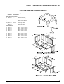
1
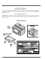
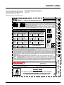
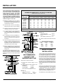
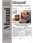
Owners &
Installation Vancouver /Montreal /St. Moritz
Manual
Model: F2101
S2101
Model: F3101
S3101
KEEP THESE INSTRUCTIONS FOR
FUTURE REFERENCE
Head Office - New Zealand
1-37 Mt Wellington Hwy.Panmure,
P.O. Box 14349
Auckland 6.
Ph. (9) 570-9009
Fax. (9) 527-1294
Australia
P.O. Box 533
Braeside, Victoria, 3195
Thank-you for purchasing a
MASPORT FIREPLACE PRODUCT.
The pride of workmanship that goes into each of our products will give you years of trouble-free enjoyment. Should
you have any questions about your product that are not covered in this manual, please contact the MASPORT
DEALER in your area.
Keep those MASPORT FIRES burning.
SAFETY NOTE: If this woodstove is not properly installed, a house fire may result. For your safety, follow the
installation instructions, contact local building or fire officials about restrictions and installation inspection requirements in your area.
MODULAR PARTS
2
Masport Freestanding Woodstove
TABLE OF CONTENTS
THE MASPORT FREESTANDING STOVE
SAFETY LABEL
Medium Freestanding Stove F2101M ................................ 4
Large Freestanding Stove F3101L .................................... 5
Medium Step Stove S2101M ............................................. 6
Large Step Stove S3101L .................................................. 7
INSTALLATION
Residential Installation ....................................................... 8
Room Air ............................................................................ 8
Modular Installation Options .............................................. 8
Minimum Clearance to Combustibles ................................ 9
- Residential "C" Vent Single Wall .............................. 9
- Residential Close Clearance .................................... 9
- Mobile Home Close Clearance ................................. 9
- Minimum Alcove Clearances .................................. 10
- Floor Protection ...................................................... 10
Stove Assembly Prior to Installation ................................ 11
- Airmate Assembly ................................................... 11
- Leg and Bottom Shield Assembly .......................... 11
- S2101 & S3101 Side Shield Adjustment ................ 11
Chimney & Connector Installation ................................... 11
- Table 1: Minimum Recommended Flue Height ..... 12
Recommended Height for Woodstove Flue .................... 12
Mobile Home Installation ................................................. 12
Listed Components for Mobile Home Installation ............ 13
Brick Flue Baffle & Secondary Air Tube Installation ........ 13
- Large Stove F3101L/S3101L ................................. 13
- Medium Stove F2101M/S2101M ............................ 14
Brick Installation ............................................................... 14
Door Handle ..................................................................... 14
Glass Installation ............................................................. 15
Blower/Fan ....................................................................... 15
Wiring Diagram ................................................................ 15
Masport Freestanding Woodstove
OPERATING INSTRUCTIONS
Draft Control ..................................................................... 16
First Fire16
Fan Operation .................................................................. 16
Ash Disposal .................................................................... 17
Safety Guidelines ............................................................. 17
MAINTENANCE
Creosote .......................................................................... 17
- Ways to Prevent & Keep Units
Free of Creosote ..................................................... 17
Maintenance of Gold Doors ............................................. 17
Latch Adjustment ............................................................. 17
Door Gasket ..................................................................... 18
Glass Maintenance .......................................................... 18
Replacement / Spare Parts .............................................. 19
WARRANTY
Warranty .......................................................................... 23
3
SAFETY LABEL
This is a copy of the label that accompanies
each Masport Medium Freestanding Woodstove (F2101M). It is located in the upper right
corner of the back of the stove. We have printed
a copy of the contents here for your review.
proved. Check the label on the unit and if there
is a difference, the label on the unit is the
correct one.
This is a copy of the label that accompanies
NOTE: Masport units are constantly being im-
101
DO NOT REMOVE THIS LABEL
ALSO
SUITABLE FOR MOBILE HOME INSTALLATION
REGENCY
TESTED TO:
MEDIUM
CSA B366.2
/
FREESTANDING STOVE ULC S627
/
UL 1482
101
F2100M
REPORT NO.6622 (FEB.1993)
INSTALL AND USE ONLY IN ACCORDANCE WITH THE MANUFACTURER'S INSTALLATION AND OPERATING
INSTRUCTIONS.
CONTACT
LOCAL
BUILDING
OR
FIRE
OFFICIALS
ABOUT
RESTRICTIONS
AND
NOV
MODEL:
DEC
LISTED SPACE HEATER, SOLID FUEL TYPE,
26 MSG BLUED STEEL CONNECTOR WITH LISTED FACTORY-BUILT CHIMNEY SUITABLE FOR USE WITH
SOLID FUELS OR MASONRY CHIMNEY.
SEE LOCAL BUILDING CODE AND MANUFACTURER'S INSTRUCTIONS FOR PRECAUTIONS REQUIRED
FOR PASSING A CHIMNEY THROUGH A COMBUSTIBLE WALL OR CEILING.
BACKWALL
D 660
mm / 26
mm / 10 in
E 420
mm / 16.5 in
in
CORNER
C 150
mm / 6
F
mm / 17.5 in
A 430
mm / 17 in
D 735
mm / 29
BACKWALL
B 280
mm / 11 in
E 445
mm / 17.5 in
CORNER
C 230
mm / 9
F
mm / 21
INSTALLATION USING LISTED DOUBLE WALL
CONNECTOR -
mm / 16 in
D 725
mm / 28.5 in
BACKWALL
B 215
mm / 8.5in
E 395
mm / 15.5 in
CORNER
C 190
mm / 7.5in
F
mm / 20
CONNECTOR SIDEWALL
in
in
A 460
MOBILE HOME
mm / 18 in
D 775
mm / 30.5 in
BACKWALL
B 215
mm / 8.5in
E 395
mm / 15.5 in
CORNER
C 215
mm / 8.5in
F
mm / 21
535
mm / 10 in
D 550
mm / 22.5
in
BACKWALL
B 115
mm / 4.5 in
E 290
mm / 11.5
in
CORNER
C 190
mm / 7.5 in
F
mm / 20
in
SIDEWALL
A 355
mm / 14 in
BACKWALL
B 180
mm / 7
CORNER
C 215
mm / 8.5in
in
D 675
mm / 26.5 in
E 355
mm / 14
in
F
mm / 21
in
535
G
G
C
F
INSTALLATION USING LISTED DOUBLE WALL
INSTALLATION USING LISTED DOUBLE WALL
CONNECTOR - ALCOVE
CONNECTOR - ALCOVE
mm / 10 in
I
570
mm / 22.5 in
SIDEWALL
G 355
mm / 14 in
I
675
mm / 26.5 in
BACKWALL
H 115
mm / 4.5in
J
290
mm / 11.5 in
BACKWALL
H 180
mm / 7
J
355
mm / 14
PROTECTION
in
MAXIMUM ALCOVE DEPTH 915 MM / 36 IN.
L
K
405 mm / 16 in
L
150 mm / 6 in
M
150 mm / 6 in
SIDE
G 255
in
BACK M
FLOOR
SIDEWALL
MINIMUM ALCOVE CEILING HEIGHT: 2.15 M / 7 FT
J
ADJACENT WALL
CONNECTOR - RESIDENTIAL CLOSE CLEARANCE
A 255
H
I
in
INSTALLATION USING LISTED DOUBLE WALL
INSTALLATION USING LISTED DOUBLE WALL
CONNECTOR - RESIDENTIAL CLOSE CLEARANCE
SIDEWALL
510
535
INSTALLATION USING LISTED DOUBLE WALL
MOBILE HOME
A 405
510
in
BACKWALL
in
SIDEWALL
mm / 14 in
B 255
CONNECTOR
SIDEWALL
A 355
BACKWALL
SIDEWALL
SINGLE WALL
SIDEWALL
SIDEWALL
445
D
RESIDENTIAL INSTALLATION USING
CONNECTOR
in
CENTER-LINE
AUG
HEATER
RESIDENTIAL INSTALLATION USING
SINGLE WALL
FLUE
FROM
E
JUL
CENTER-LINE
SIDEWALL
HEATER
B
A
JUN
MEASURE
FLUE
FROM
WITHOUT AIRMATE SHIELD
MAY
F2100M
SIDEWALL
F2100M WITH AIRMATE SHIELD
SEPT
FLUE SERVING ANOTHER APPLIANCE.
MINIMUM CLEARANCES TO COMBUSTIBLE MATERIALS
MEASURE
DO NOT PASS CHIMNEY
CONNECTOR THROUGH COMBUSTIBLE WALL OR CEILING. DO NOT CONNECT THIS UNIT TO A CHIMNEY
K FRONT
MINIMUM CLEARANCES FOR HORIZONTAL CONNECTOR TO CEILING: 455 MM / 18"
THE SPACE BENEATH THE HEATER MUST NOT BE OBSTRUCTED. OPERATE ONLY WITH FIREBRICKS IN PLACE.
FOR USE WITH SOLID WOOD FUEL ONLY. USE OF OTHER FUELS MAY DAMAGE HEATER AND CREATE A HAZARDOUS CONDITION. DO NOT OBSTRUCT
COMBUSTION AIR OPENINGS. OPERATE ONLY WITH FIREBRICKS IN PLACE. OPERATE ONLY WITH DOOR CLOSED - OPEN FEED DOOR TO FEED FIRE
ONLY. DO NOT USE GRATE OR ELEVATE FIRE. BUILD WOOD FIRE DIRECTLY ON HEARTH. DO NOT OVERFIRE - IF HEATER OR CHIMNEY CONNECTOR
GLOWS YOU ARE OVERFIRING. INSPECT AND CLEAN CHIMNEY AND CONNECTOR FREQUENTLY. UNDER CERTAIN CONDITIONS OF USE CREOSOTE
APR
AIRMATE SHIELD
MAR
AIRMATE SHIELD
FEB
F2100M WITHOUT
SIDE
F2100M WITH
OCT
INSTALLATION INSPECTION IN YOUR AREA. USE 150 MM (6 IN.) DIAMETER MINIMUM 24 MSG BLACK OR
NEOCERAM GLASS. COMBUSTIBLE FLOOR MUST BE PROTECTED BY NON-COMBUSTIBLE MATERIAL EXTENDING BENEATH THE HEATER AND TO
THE FRONT AND SIDES AS INDICATED OR TO THE NEAREST PERMITTED COMBUSTIBLE MATERIAL.
OPTIONAL COMPONENT: FAN, ELECTRICAL RATING: VOLTS 115, 60 HZ, 2 AMPS
JAN
BUILDUP MAY OCCUR RAPIDLY. KEEP FURNISHINGS AND OTHER COMBUSTIBLE MATERIAL AWAY FROM HEATER. REPLACE GLASS ONLY WITH
COMPONENTS REQUIRED FOR MOBILE HOME INSTALLATION: OUTSIDE AIR KIT AND ONE OF THE FOLLOWING DOUBLE WALL CONNECTOR
IN CANADA:
LISTED SECURITY MODEL DP, OR OLIVER MACLEOD PRO-VENT PV DOUBLE WALLED CONNECTOR WITH LISTED CHIMNEY SYSTEM:
SECURITY MODEL S2100, ICC EXCEL 2100.
IN USA:
LISTED DOUBLE WALL CONNECTORS SECURITY MODEL DP, SELKIRK MODEL DS, OLIVER MACLEOD PRO VENT PV, SIMPSON DURA
VENT MODEL DVL, GSW SUPER PIPE 6, METAL-FAB DOUBLE WALL.
CONNECTED TO ONE OF THE FOLLOWING COMPATIBLE CHIMNEY SYSTEMS
SECURITY MODEL S2100 OR MODEL ASHT, SELKIRK MODEL SSII, OLIVER MACLEOD PRO JET 3103, SIMPSON DURA PLUS, GSW MODEL SC OR METAL-
DELTA, BC
V4G 1H4
MADE IN CANADA
UNITED STATES
ENVIRONMENTAL
PROTECTION
AGENCY
CERTIFIED TO COMPLY WITH
JULY 1990,
PARTICULATE EMISSION STANDARDS.
CAUTION
HOT WHILE IN OPERATION DO NOT TOUCH.
KEEP CHILDREN,
CLOTHING AND FURNITURE AWAY. CONTACT MAY CAUSE
SKIN BURNS. READ NAMEPLATE AND INSTRUCTIONS.
WD
908-282
rev. 02/00
Note: Hard copy - exact size 8" x 5-3/4".
2003
6988 VENTURE ST.
2002
FIREPLACE PRODUCTS INTERNATIONAL LTD.
2001
MANUFACTURED BY:
DATE OF MANUFACTURE
FAB TEMP/GUARD, AMERI-TEC HS, ICC EXCEL 2100 . USE CHIMNEY COMPONENTS AS SPECIFIED IN INSTALLATION INSTRUCTIONS.
On disc, print at 65% to achieve actual size.
Everything printed black on grey except what is indicated is printed red on gray.
4
Masport Freestanding Woodstove
November 14, 2001: Updated to new serial number system - Otherwise no change to artwork.
SAFETY LABEL
proved. Check the label on the unit and if there
is a difference, the label on the unit is the
correct one.
each Masport Large Freestanding Woodstove
(F3101L). It is located in the upper right corner
of the back of the stove. We have printed a copy
of the contents here for your review.
NOTE: Masport units are constantly being im-
SUITABLE FOR
DO NOT REMOVE THIS LABEL
MOBILE HOME INSTALLATION
102
REGENCY LARGE FREESTANDING STOVE - F3100L
CSA B366.2 / ULC S627 / UL 1482
REPORT NO.6623 (MAY 93)
INSTALL AND USE ONLY IN ACCORDANCE WITH THE MANUFACTURER'S INSTALLATION AND OPERATING INSTRUCTIONS.
CONTACT LOCAL BUILDING OR FIRE OFFICIALS ABOUT RESTRICTIONS AND
INSTALLATION INSPECTION IN YOUR AREA. USE 150 MM (6 IN.) DIAMETER MINIMUM 24 MSG BLACK OR
NOV
MODEL:
TESTED TO:
DEC
LISTED SPACE HEATER, SOLID FUEL TYPE,
SOLID FUELS OR MASONRY CHIMNEY.
SEE LOCAL BUILDING CODE AND MANUFACTURER'S INSTRUCTIONS FOR PRECAUTIONS REQUIRED
FOR PASSING A CHIMNEY THROUGH A COMBUSTIBLE WALL OR CEILING.
BACKWALL
in
BACKWALL
B 305
mm / 12 in
E 470
mm / 18.5 in
CORNER
C 215
mm / 8.5in
F
mm / 22
560
in
BACKWALL
mm / 20
in
D 860
mm / 34
BACKWALL
B 355
mm / 14
in
E 520
mm / 20.5 in
CORNER
C 265
mm / 10.5 in
F
mm / 24
610
in
in
INSTALLATION USING LISTED DOUBLE WALL
CONNECTOR -
MOBILE HOME
SIDEWALL
A 460
mm / 18 in
D 810
mm / 32
in
BACKWALL
B 240
mm / 9.5in
E 405
mm / 16
in
CORNER
C 255
mm / 10 in
F
mm / 23.5 in
595
CONNECTOR
A 510
INSTALLATION USING LISTED DOUBLE WALL
CONNECTOR -
SINGLE WALL
SIDEWALL
MOBILE HOME
SIDEWALL
A 510
mm / 20 in
D 860
BACKWALL
B 305
mm / 12 in
E 470
mm / 18.5 in
CORNER
C 255
mm / 10 in
F
mm / 23.5 in
595
mm / 34
CONNECTOR - RESIDENTIAL CLOSE CLEARANCE
SIDEWALL
A 405
mm / 16 in
D 760
mm / 30
in
SIDEWALL
A 510
mm / 20 in
D 860
mm / 34
B 240
mm / 9.5in
E 405
mm / 16
in
BACKWALL
B 305
mm / 12 in
E 470
mm / 18.5 in
CORNER
C 215
mm / 8.5in
F
mm / 22
in
CORNER
C 215
mm / 8.5in
F
mm / 22
560
560
G
G
ADJACENT WALL
CONNECTOR - RESIDENTIAL CLOSE CLEARANCE
BACKWALL
J
I
in
INSTALLATION USING LISTED DOUBLE WALL
INSTALLATION USING LISTED DOUBLE WALL
H
in
C
F
in
BACK M
FLOOR
INSTALLATION USING LISTED DOUBLE WALL
SIDEWALL
G 405
mm / 16 in
I
760
mm / 30
in
BACKWALL
H 240
mm / 9.5in
J
405
mm / 16
in
L
PROTECTION
ALCOVE INSTALLATION
REQUIRES AIRMATE SHIELD
K
405 mm / 16 in
L
150 mm / 6 in
M
150 mm / 6 in
SIDE
CONNECTOR - ALCOVE
JUL
mm / 32
JUN
D 810
MAY
CONNECTOR
mm / 18 in
D
SIDEWALL
A 460
CENTER-LINE
SIDEWALL
SINGLE WALL
HEATER
E
RESIDENTIAL INSTALLATION USING
RESIDENTIAL INSTALLATION USING
SIDEWALL
FLUE
FROM
CENTER-LINE
SIDEWALL
HEATER
B
A
Note: Final size is 65% of artwork on Pagemaker file.
MEASURE
FLUE
FROM
WITHOUT AIRMATE SHIELD
AUG
F3100L
APR
F3100L WITH AIRMATE SHIELD
SEPT
FLUE SERVING ANOTHER APPLIANCE.
MINIMUM CLEARANCES TO COMBUSTIBLE MATERIALS
MEASURE
DO NOT PASS CHIMNEY
CONNECTOR THROUGH COMBUSTIBLE WALL OR CEILING. DO NOT CONNECT THIS UNIT TO A CHIMNEY
AIRMATE SHIELD
K FRONT
MINIMUM CLEARANCE BETWEEN HORIZONTAL CHIMNEY CONNECTOR AND COMBUSTIBLE MATERIALS - 460 MM (18 IN.). CLEARANCE MAY BE
REDUCED BY THE USE OF LISTED PIPE SHIELDS, WALL PROTECTORS OR OTHER MEANS APPROVED BY LOCAL BUILDING OR FIRE OFFICIALS.
COMBUSTIBLE FLOOR MUST BE PROTECTED BY NON-COMBUSTIBLE MATERIAL EXTENDING BENEATH THE HEATER AND TO THE FRONT AND SIDES
MAR
AIRMATE SHIELD
F3100L WITHOUT
SIDE
WITH
SIDEWALL
F3100L
OCT
26 MSG BLUED STEEL CONNECTOR WITH LISTED FACTORY-BUILT CHIMNEY SUITABLE FOR USE WITH
FOR USE WITH SOLID WOOD FUEL ONLY. USE OF OTHER FUELS MAY DAMAGE HEATER AND CREATE A HAZARDOUS CONDITION. DO NOT OBSTRUCT
COMBUSTION AIR OPENINGS. OPERATE ONLY WITH FIREBRICKS IN PLACE. OPERATE ONLY WITH DOOR CLOSED - OPEN FEED DOOR TO FEED FIRE
ONLY. DO NOT USE GRATE OR ELEVATE FIRE. BUILD WOOD FIRE DIRECTLY ON HEARTH. DO NOT OVERFIRE - IF HEATER OR CHIMNEY CONNECTOR
FEB
AS INDICATED OR TO THE NEAREST PERMITTED COMBUSTIBLE MATERIAL.
GLOWS YOU ARE OVERFIRING. INSPECT AND CLEAN CHIMNEY AND CONNECTOR FREQUENTLY. UNDER CERTAIN CONDITIONS OF USE CREOSOTE
JAN
NEOCERAM GLASS.
OPTIONAL COMPONENT: FAN, ELECTRICAL RATING: VOLTS 115, 60 HZ, 2 AMPS
COMPONENTS REQUIRED FOR MOBILE HOME INSTALLATION: OUTSIDE AIR KIT AND ONE OF THE FOLLOWING DOUBLE WALL CONNECTOR
IN CANADA:
Date: September 14, 2001
BUILDUP MAY OCCUR RAPIDLY. KEEP FURNISHINGS AND OTHER COMBUSTIBLE MATERIAL AWAY FROM HEATER. REPLACE GLASS ONLY WITH
LISTED SECURITY MODEL DP, OR OLIVER MACLEOD PRO-VENT PV DOUBLE WALLED CONNECTOR WITH LISTED CHIMNEY SYSTEM:
SECURITY MODEL S2100, ICC EXCEL 2100.
IN USA:
LISTED DOUBLE WALL CONNECTORS SECURITY MODEL DP, SELKIRK MODEL DS, OLIVER MACLEOD PRO VENT PV, SIMPSON DURA
VENT MODEL DVL, GSW SUPER PIPE 6, METAL-FAB DOUBLE WALL. CONNECTED TO ONE OF THE FOLLOWING COMPATIBLE CHIMNEY SYSTEMS
SECURITY MODEL S2100 OR MODEL ASHT, SELKIRK MODEL SSII, OLIVER MACLEOD PRO JET 3103, SIMPSON DURA PLUS, GSW MODEL SC OR METAL-
DELTA, BC
UNITED STATES
ENVIRONMENTAL
PROTECTION
AGENCY
V4G 1H4
CERTIFIED TO COMPLY WITH
MADE IN CANADA
JULY 1990,
PARTICULATE EMISSION STANDARDS.
CAUTION
HOT WHILE IN OPERATION DO NOT TOUCH.
KEEP CHILDREN,
CLOTHING AND FURNITURE AWAY. CONTACT MAY CAUSE
SKIN BURNS. READ NAMEPLATE AND INSTRUCTIONS.
Masport Freestanding Woodstove
WD
908-351
2003
6988 VENTURE ST.
2002
FIREPLACE PRODUCTS INTERNATIONAL LTD.
2001
MANUFACTURED BY:
DATE OF MANUFACTURE
FAB TEMP/GUARD, AMERI-TEC HS, ICC EXCEL 2100 . USE CHIMNEY COMPONENTS AS SPECIFIED IN INSTALLATION INSTRUCTIONS.
09/00
5
Everything printed black on grey except what is highlighted in yellow is printed red on gray.
102
SAFETY LABEL
This is a copy of the label that accompanies
each Regency Medium Freestanding Step
Woodstove (S2101). It is located in the upper
right corner of the back of the stove. We have
printed a copy of the contents here for your
review.
NOTE: Regency units are constantly being
improved. Check the label on the unit and if
there is a difference, the label on the unit is the
correct one.
TESTED TO:
CSA B366.2 / ULC S627 / UL 1482
REPORT NO.6622 (FEB.1993)
INSTALL AND USE ONLY IN ACCORDANCE WITH THE MANUFACTURER'S INSTALLATION AND OPERATING INSTRUCTIONS.
On disc, print at 65% to achieve actual size.
WH-
MODEL: REGENCY MEDIUM FREESTANDING STEP STOVE - S2100M
CONTACT LOCAL BUILDING OR FIRE OFFICIALS ABOUT RESTRICTIONS AND INSTALLATION INSPECTION IN YOUR AREA. USE
CHIMNEY SUITABLE FOR USE WITH SOLID FUELS OR MASONRY CHIMNEY.
SEE LOCAL BUILDING CODE AND MANUFACTURER'S INSTRUCTIONS FOR PRECAUTIONS REQUIRED FOR PASSING A CHIMNEY
D
660
mm / 26
BACKWALL
B 255
mm / 10 i n
E
420
mm / 16.5 i n
CORNER
C 150
mm / 6
F
445
mm / 17.5 i n
in
in
D
mm / 16 i n
D
725
SIDEWALL
A 405
mm / 28.5 i n
BACKWALL
B 215
mm / 8.5 i n
E
395
mm / 15.5 i n
CORNER
C 190
mm / 7.5 i n
F
510
mm / 20
in
H
J
G
G
SIDEWALL
SIDEWALL
INSTALLATION USING LISTED DOUBLE WALL CONNECTOR RESIDENTIAL CLOSE CLEARANCE
A 255
mm / 10 i n
D
550
BACKWALL
B 115
mm / 4.5 i n
E
290
mm / 11.5 i n
CORNER
C 190
mm / 7.5 i n
F
510
mm / 20
INSTALLATION USING LISTED DOUBLE WALL CONNECTOR - ALCOVE
SIDEWALL
G 255
mm / 10 i n
I
570
mm / 22.5 i n
BACKWALL
H 115
mm / 4.5 i n
J
290
mm / 11.5 i n
16 in
/
6
in
150 mm
/
6
in
MINIMUM ALCOVE CEILING HEIGHT:
2.15 M / 7 FT
915 MM / 36 IN.
ADJACENT WALL
in
/
150 mm
M
MAXIMUM ALCOVE DEPTH:
I
mm / 22.5 i n
SIDEWALL
SIDEWALL
405 mm
L
K FRONT
BACKWALL
INSTALLATION USING LISTED DOUBLE WALL CONNECTOR - MOBILE HOME
K
C
MINIMUM CLEARANCES FOR HORIZONTAL
CONNECTOR TO CEILING:
455 MM / 18"
F
THE SPACE BENEATH THE HEATER MUST
NOT BE OBSTRUCTED. OPERATE ONLY
WITH FIREBRICKS IN PLACE.
FOR USE WITH SOLID WOOD FUEL ONLY. USE OF OTHER FUELS MAY DAMAGE HEATER AND CREATE A HAZARDOUS CONDITION. DO NOT OBSTRUCT
COMBUSTION AIR OPENINGS. OPERATE ONLY WITH FIREBRICKS IN PLACE. OPERATE ONLY WITH DOOR CLOSED - OPEN FEED DOOR TO FEED FIRE ONLY.
DO NOT USE GRATE OR ELEVATE FIRE. BUILD WOOD FIRE DIRECTLY ON HEARTH. DO NOT OVERFIRE - IF HEATER OR CHIMNEY CONNECTOR GLOWS YOU
ARE OVERFIRING. INSPECT AND CLEAN CHIMNEY AND CONNECTOR FREQUENTLY. UNDER CERTAIN CONDITIONS OF USE CREOSOTE BUILDUP MAY OCCUR
RAPIDLY.
Note: Hard copy - exact size 8" x 5-3/4".
mm / 14 i n
L
A
JUL
A 355
BACK M
JUN
SIDEWALL
E
KEEP FURNISHINGS AND OTHER COMBUSTIBLE MATERIAL AWAY FROM HEATER.
MAY
RESIDENTIAL INSTALLATION USING SINGLE WALL CONNECTOR
B
SIDE
CENTER-LINE
SIDE
SIDEWALL
HEATER
FLOOR PROTECTION
BACKWALL
FLUE
FROM
APR
S2100 MINIMUM CLEARANCES TO COMBUSTIBLE MATERIALS
MEASURE
AUG
SEPT
DO NOT PASS CHIMNEY CONNECTOR THROUGH COMBUSTIBLE WALL OR
CEILING. DO NOT CONNECT THIS UNIT TO A CHIMNEY FLUE SERVING ANOTHER APPLIANCE.
MAR
THROUGH A COMBUSTIBLE WALL OR CEILING.
REPLACE GLASS ONLY WITH NEOCERAM GLASS.
COMBUSTIBLE FLOOR MUST BE PROTECTED BY NON-COMBUSTIBLE MATERIAL EXTENDING BENEATH THE HEATER AND TO THE FRONT AND SIDES AS
INDICATED OR TO THE NEAREST PERMITTED COMBUSTIBLE MATERIAL.
OPTIONAL COMPONENT: FAN, ELECTRICAL RATING: VOLTS 115, 60 HZ, 2 AMPS
FEB
S2100M
OCT
150 MM (6 IN.) DIAMETER MINIMUM 24 MSG BLACK OR 26 MSG BLUED STEEL CONNECTOR WITH LISTED FACTORY-BUILT
IN CANADA:
LISTED SECURITY MODEL DP, OR OLIVER MACLEOD PRO-VENT PV DOUBLE WALLED CONNECTOR WITH
LISTED CHIMNEY SYSTEM:
SECURITY MODEL S2100, ICC EXCEL 2100.
IN USA:
LISTED DOUBLE WALL CONNECTORS SECURITY MODEL DP, SELKIRK MODEL DS, OLIVER MACLEOD PRO VENT PV, SIMPSON DURA VENT
JAN
COMPONENTS REQUIRED FOR MOBILE HOME INSTALLATION: OUTSIDE AIR KIT AND ONE OF THE FOLLOWING DOUBLE WALL CONNECTOR
Everything printed black on grey except what is highlighted in yellow is printed red on gray.
DO NOT REMOVE THIS LABEL
ALSO
SUITABLE FOR MOBILE HOME INSTALLATION
NOV
LISTED SPACE HEATER, SOLID FUEL TYPE,
DEC
WH-
MODEL DVL, GSW SUPER PIPE 6, METAL-FAB DOUBLE WALL. CONNECTED TO ONE OF THE FOLLOWING COMPATIBLE CHIMNEY SYSTEMS SECURITY
MODEL S2100 OR MODEL ASHT, SELKIRK MODEL SSII, OLIVER MACLEOD PRO JET 3103, SIMPSON DURA PLUS, GSW MODEL SC OR METAL-FAB TEMP/
GUARD, AMERI-TEC HS, ICC EXCEL 2100 . USE CHIMNEY COMPONENTS AS SPECIFIED IN INSTALLATION INSTRUCTIONS.
AGENCY
CERTIFIED TO COMPLY WITH
JULY 1990,
PARTICULATE EMISSION STANDARDS.
CAUTION
HOT WHILE IN OPERATION DO NOT TOUCH.
KEEP CHILDREN,
CLOTHING AND FURNITURE AWAY. CONTACT MAY CAUSE
SKIN BURNS. READ NAMEPLATE AND INSTRUCTIONS.
WD
908-733
rev. 02/00
6
logo. No other changes.
ENVIRONMENTAL
PROTECTION
MADE IN CANADA
July 25/01: Updated Regency
UNITED STATES
V4G 1H4
2001
DELTA, BC
2000
6988 VENTURE ST.
2002
FIREPLACE PRODUCTS INTERNATIONAL LTD.
DATE OF MANUFACTURE
MANUFACTURED BY:
Masport Freestanding Woodstove
SAFETY LABEL
This is a copy of the label that accompanies
each Regency Large Freestanding Step Woodstove (S3101). It is located in the upper right
corner of the back of the stove. We have
printed a copy of the contents here for your
review.
Masport Freestanding Woodstove
NOTE: Regency units are constantly being
improved. Check the label on the unit and if
there is a difference, the label on the unit is the
correct one.
7
INSTALLATION
RESIDENTIAL
INSTALLATION
1) Read all instructions before installing your
Masport Stove. Install and use only in accordance with these installation and operating instructions. Be aware that local Codes
and Regulations may override some items
in this manual. Check with your local inspector.
2) Select a position for your Masport Stove.
Consult the minimum clearance chart for
your model and set the stove in place. For
close clearance installation use listed double wall connector systems (see page 13).
3) To insure vertical alignment, suspend a
plumb bob from the ceiling over the exact
center of your stove flue and mark a spot on
the ceiling to indicate the center of the
chimney.
4) Check that the area above the ceiling is
clear for cutting. Re-confirm the clearance
from the stove to combustibles to insure
that they are within the prescribed limits.
5) Install chimney according to chimney manufacturers instructions. The performance
of your woodstove is governed to a very
large part by the chimney system. Too
short a chimney can cause difficult startup, dirty glass, backsmoking when door is
open, and even reduced heat output. Too
tall a chimney may prompt excessive draft
which can result in very short burn times
and excessive heat output. The use of an
inexpensive flue pipe damper may be helpful in reducing excessive draft.
8
CAUTION: The chimney should be the same
size as the flue outlet on the stove. The chimney must be listed as suitable for use with solid
fuels. For other types of chimneys check with
your local building code officials. Do not confuse a chimney with a type “B” Venting System
used for gas appliances as suitable for a wood
burning appliance. For Mobile Home installations refer to that section on page 12.
6) Mark the location of the pedestal base or
legs on the floor, then move the stove aside
and mark the position of the floor protector.
11) Do not connect this unit to a chimney
serving another appliance unless approved
by your local building authority.
12) A chimney connector cannot pass through
an attic or roof space, closet or similar
concealed space, or a floor, ceiling, wall or
partition of combustible construction. In
Canada, if passage through a wall, or partition of combustible construction is desired, the installation shall conform to CAN/
CSA-B365, Installation Code for Solid-FuelBurning Appliances and Equipment.
7) The floor protector must be of non-combustible material and must extend
16"(406mm) in front of the door opening
and 6"(152mm) to the sides and rear of the
unit. Some areas may require a larger size
floor protector. See your local inspector.
For outside air installation refer to Mobile
Home installation instructions on page 12.
13) Your Masport Woodstove is not to be connected to any air distribution duct.
8) When the floor protection is complete, position the stove with the flue collar centered
under the installed chimney.
For installation using room air for combustion,
remove knockout from the pedestal, and/or
from the bottom if using a heat shield.
9) In seismically active areas, Masport recommends that your unit is secured to the
floor by using the bolt down holes inside the
pedestal (the same ones used in Mobile
Home installations).
Mobile home installations require the use of
outside air.
10) For residential installations using "C" Vent
(single wall) the chimney connector must
be at least 24 gauge steel. Do not use
galvanized pipe. For Mobile Home installation refer to the Mobile Home installation
instructions on page 12.
ROOM AIR IMPORTANT
On pedestal units there are two locations where
outside air may be adapted to the unit. If using
the bottom of the pedestal, do not remove
knockout from the rear of the pedestal. Only
remove rear knockout if outside air will be
brought in from the rear.
On leg units outside air can only be brought in
from the bottom of the heat shield.
Note:
Once the knockout is removed there
are two tabs remaining. Bend both
tabs out for ease of installation when
attaching outside air.
Masport Freestanding Woodstove
INSTALLATION
MINIMUM CLEARANCE TO COMBUSTIBLE MATERIALS
Please read the section below carefully .
Measurements "From Unit" are from the top plate of the stove to a side wall or to a corner,
and from the rear heat shield to a back wall.
Residential Installation “C” Vent (Single Wall)
From
Unit
Unit
From
Corner
From
Flue Center-line
Medium F2101M
with Airmate
A
355mm
B
255mm
C
150mm
D
660mm
E
420mm
F
445mm
Medium S2101M
Step Stove
355mm
255mm
150mm
660mm
420mm
445mm
Large F3101L
with Airmate
460mm
305mm
215mm
810mm
470mm
560mm
Large S3101L
Step Stove
460mm
305mm
215mm
810mm
470mm
560mm
Residential Close Clearance (To be installed with required pipe components)
When the stove is installed as a close clearance residential unit, a listed double wall connector is required from the stove collar to the ceiling
level.
From
Unit
Unit
From
Flue Center-line
From
Corner
Medium F2101M
with Airmate
A
255mm
B
115mm
C
190mm
D
570mm
E
290mm
F
510mm
Medium S2101M
Step Stove
255mm
115mm
190mm
570mm
290mm
510mm
Large F3101L
with Airmate
405mm
240mm
215mm
760mm
405mm
560mm
Large S3101L
Step Stove
405mm
240mm
215mm
760mm
405mm
560mm
Mobile Home Close Clearance (To be installed with required pipe components)
"C" Vent single wall pipe is not approved for Mobile Home installations. (Refer to Mobile Home Instructions.)
Unit
From
Unit
From
Corner
From
Flue Center-line
A
B
C
D
E
F
Medium F2101M
with Airmate
405mm
215mm
190mm
725mm
395mm
510mm
Medium S2101M
Step Stove
405mm
215mm
190mm
725mm
395mm
510mm
Large F3101L
with Airmate
460mm
240mm
255mm
810mm
405mm
595mm
Large S3101L
Step Stove
460mm
240mm
255mm
810mm
405mm
595mm
Masport Freestanding Woodstove
9
INSTALLATION
Minimum Alcove Clearance to Combustible Materials
The Masport Freestanding models have been alcove approved and must
be installed with a listed double wall connector to the ceiling level.
Note:
Minimum alcove ceiling height - 2134mm
Maximum depth of alcove - 914mm
Unit
From
From Flue
Unit
Center-line
Min.
Min.Hearth
Width
to Rear Wall
G
H
I
J
K
L
Medium F2101M
with Airmate
255mm
115mm
551mm
290mm
1120mm
1055mm
Medium S2101M
Step Stove
255mm
115mm
551mm
290mm
1120mm
1055mm
Large F3101L
with Airmate
405mm
240mm
760mm
405mm
1525mm
1180mm
Large S3101L
Step Stove
405mm
240mm
760mm
405mm
1525mm
1180mm
Floor Protection
A combustible floor must be protected by a non-combustible material (like tile,
concrete board, or certified to UL-1618 or as defined by local codes) extending
beneath the heater and a minimum of 6"(150mm) from each side and minimum
16"(405mm) from the front face of the stove and minimum 6"(150mm) (or the
rear clearance to combustibles whichever is smaller) from the
rear of the stove.
Minimum Overall Width (X) of Floor
Protector for all installations:
Medium Stove
F2101M /S2101M 915mm
Large Stove
F3101L/ S3101L 1000mm
Minimum Overall Depth (Y) of Floor Protector
Unit
Residential
Residential
Mobile Home
"C" Vent
Close Clearance
Close Clearance
Alcove
Medium F2101M
with Airmate
Y
1090mm
Z
150mm
Y
1055mm*
Z
115mm
Y
1090mm
Z
150mm
Y
1055mm*
Z
115mm
Medium S2101M
Step Stove
1090mm
150mm
1055mm*
115mm
1090mm
150mm
1055mm*
115mm
Large F3101L
with Airmate
1090mm
150mm
1090mm*
150mm
1090mm
150mm
1090mm*
150mm
Large S3101L
Step Stove
1090mm
150mm
1090mm*
150mm
1090mm
150mm
1090mm*
150mm
*The rear clearance to combustibles is less than 6"(150mm), for corner installations the rear corners may be angled to take advantage of the closer
clearances.
10
Masport Freestanding Woodstove
INSTALLATION
STOVE ASSEMBLY PRIOR TO
INSTALLATION
The stove requires either the Airmate and the
4 legs attached to the base.
Airmate Assembly
Medium
Large
850-105
850-305
1) The airmate sits on top of the stove with the
slots in the sides fitting over the curved
deflector on the rear stove top. See diagram 1.
2) Center the airmate and push it forward to
the front of the stove. The back of the
airmate should be level with the back and
sides of the rear heat shield. See diagrams
2 & 3.
Leg Assembly
Bottom Shield
Medium
Large
850-221
850-321
It will be easier to attach the legs to the stove if
it is tipped on its back (preferably on a soft
surface to prevent scratching).
1) Loosen the bolts and washers in the four
corners of the bottom the unit (do one leg at
a time or the entire bottom shield will come
off). The cast legs can be slipped in under
the washer and then re-tighten the bolts.
S2101M & S3101L Side Shield
Adjustment
The left and right side shields are lowered for
shipping and handling. It allows for a handhold
on the top of the stove. Before placing in the
Step Stove in its final position, the side shields
must be raised.
Loosen the screws on the rear on the stove (3
per side), slide the side panel up as far as
possible and then secure by tightening the
screws.
2) Level the stove by adjusting the levelling
bolts in the bottom of each leg.
STEP BY STEP
CHIMNEY AND
CONNECTOR
INSTALLATION:
Note:
Diagram 1
These are a generic set of chimney
installation instructions. Always
follow the manufacturers own instructions explicitly. Check Table 1
on page 12 for the Minimum Recommended Flue Heights.
1) With your location already established, cut
and frame the roof hole. It is recommended
that no ceiling support member be cut for
chimney and support box installation. If it is
necessary to cut them, the members must
be made structurally sound.
2) Install radiant shield and support from above.
Diagram 2
3) Stack the insulated pipe onto your finish
support to a minimum height of 3 feet
(75mm) above the roof penetration, or 2
feet (50mm) above any point within 10 feet
(250mm) measured horizontally. There
must be at least 3 feet (75mm) of chimney
above the roof level.
Diagram 3
Masport Freestanding Woodstove
11
INSTALLATION
Note: Increasing the chimney height above
this minimum level will sometimes help
your unit to “breathe” better by allowing a
greater draft to be created. This greater
draft can decrease problems such as, difficult start-ups, backsmoking when door is
open, and dirty glass. It might be sufficient
to initially try with the minimum required
height, and then if problems do arise add
additional height at a later date.
4) Slide the roof flashing over your chimney
and seal the flashing to the roof with roofing compound. Secure the flashing to your
roof with nails or screws.
5) Place the storm collar over the flashing,
sealing the joints with a silicone caulking.
6) Fasten the raincap with spark screens (if
required) to the top of your chimney.
TABLE 1
MINIMUM RECOMMENDED FLUE HEIGHTS IN METERS
(Measured from the top of the unit)
ELEVATION
(METERS ABOVE
SEA LEVEL
0-305
305-610
610-915
915-1220
1220-1525
1525-1830
1830-2135
2135-2440
2440-2745
2745-3050
# OF ELBOWS
0
2 x 15o
4 x 15o
2 x 30o
4 x 30o
2 x 45o
4 x 45o
3.7
3.8
4.0
4.1
4.3
4.4
4.6
4.7
4.9
5.0
4.0
4.1
4.3
4.4
4.6
4.7
4.9
5.0
5.2
5.3
4.3
4.4
4.6
4.7
4.9
5.2
5.3
5.5
5.6
5.8
4.6
4.7
4.9
5.2
5.3
5.5
5.6
5.8
6.1
6.2
5.5
5.8
5.9
6.1
6.4
6.6
6.9
7.0
7.3
7.5
4.9
5.0
5.2
5.5
5.6
5.8
6.1
6.2
6.4
6.7
6.1
6.4
6.6
6.9
7.0
7.3
7.6
7.8
8.1
8.2
No more than two offsets (four elbows) allowed.
7) For optimum efficiency when installing into
a masonry chimney, size accordingly, i.e.
the 6"(150mm) flue dia. is 28.28 sq.in (720
sq.mm).
Example: b)
One 90 deg. elbow
= 0.610m
2m of horizonatal run= 4.0m
one "T"
= 0.915m
Total Addition (at sea level) = 5.5m
8) To complete your chimney installation, install the double wall connector pipe from
the stove’s flue collar to the chimney support device.
3) Add 4% overall for each 305m above sea
level.
9) If you are using a horizontal connector, the
chimney connector should be as high as
possible while still maintaining the
18"(460mm) minimum distance from the
horizontal connector to the ceiling.
Recommended Flue Height
Elevation Example a) Example b)
0m
7.6m
9.2m
305m
7.9m
9.6m
610m
8.2m
9.9m
1525m
8.5m
10.3m
2440m
8.8m
10.7m
10) NOTE: Residential Close Clearance and
Alcove installations require a listed double
wall connector from the stove collar to the
ceiling level.
The your
diagrams
below
illustrateceiling
one way
to in-a
stall
unit into
a standard
or with
horizontal connector. Check with your dealer or
installer for information on other options available to you.
MOBILE HOME
INSTALLATION
Horizontal Installation
RECOMMENDED
HEIGHTS FOR
WOODSTOVE FLUE
Simple rules on draft. See Table 1.
1) At sea level minimum height is 3.7m
straight.
2) Add the following vertical height to compensate for:
45 deg. elbow
= 0.305m
90 deg. elbow
= 0.610m
"T"
= 0.915m
Each meter of horizontal run = 2.0m
Standard Ceiling Installation
12
Example: a)
1.5m of horizontal run
= 3.0m
one "T"
= 0.915m
Total Addition (at sea level) = 3.9m
Once you have properly marked the position of
your unit and the floor protection as outlined in
the Residential Installation items #1 through
#8, a supply of fresh air has to be supplied to
your unit. Cut a minimum 3 inch diameter hole
through your floor protector and the floor directly under your pedestal base to the outside.
Use 3" (76mm) duct pipe with a mesh grill to
pipe fresh air into the pedestal area. Block off
the hole in the back of the pedestal with the
square plate and the two 1/2" (13mm) screws
provided.
Place your unit in position and secure it to the
floor using two lag bolts 3/8" x 3-1/2" (9.5mm
x 89mm) through the two holes inside the
pedestal base. It is important to maintain the
structural integrity of the Mobile Home floor,
walls and roof when installing your unit.
For Mobile Home units installed in the U.S. the
Masport Freestanding Woodstove
INSTALLATION
1
CPE
Rain Cap
SECURITY S2101
Qty. Part #
Description
1 DL42A-6
Connector Kit
1 6XSF
Support
1 6XFA
Flashing
1 6XL3
Chimney Length
1 6XL18
Chimney Length
1 6XCPE
Rain Cap
METAL-FAB TEMP/GUARD 2100
Qty. Part #
Description
1 6DWBK
Connector
1 6TGRS
Roof Support
1 6TGG36
Chimney Length
1 6TGG12
Chimney Length
1 6TGF
Flashing
1 6TGC
Rain Cap
unit must be grounded using a #8 ground wire
with approved termination and star washer.
LISTED COMPONENTS
FOR MOBILE HOME
INSTALLATION
The Masport Small, Medium and Large Freestanding pedestal units are approved for installation in a Mobile Home if one of the following
pipe systems is used.
METALBESTOS
Qty. Part #
1 6DS-VK
1 6TMH
1 6TAF-6
1 6T-36
1 6T-18
1 6T-CT
SSII
Description
Connector Kit
Shield/Support
Flashing
Chimney Length
Chimney Length
Rain Cap
PRO-JET 3103
Qty. Part #
1 PV06-TK
1 CSB
1 RRS
1 LFR03
1 SL3
1 SL1
1 RCSA
Description
Connector
Shield/Support
Radiation Shield
Flashing
Chimney Length
Chimney Length
Rain Cap
SECURITY ASHT
Qty. Part #
Description
1 DL42A-6
Connector Kit
1 6SS
Shield/Support
1 6FAMH
Flashing
1 6L3
Chimney Length
1 6L1
Chimney Length
Masport Freestanding Woodstove
AMERI-TEC HS
Qty. Part #
1 6DCC
1 6HSRS-12
BK)
1 6F
1 6HS-36
1 6HS-18
1 6HS-RCS
Description
Connector
Roof Support (6PLRS-12Flashing
Chimney Length
Chimney Length
Rain Cap (6PL-MPC)
SIMPSON DURA-PLUS
Qty. Part #
Description
1 6DVL8693 Connector Kit
1 6DP-MH9096 Mobile Home Kit
ICC EXCEL 2100
Qty. Part #
Description
1 6CL48
48" Chimney length
(also in 12", 18", 24" lengths.
1 6RC
Rain Cap
1 6RCS
Spark Screen (for rain cap)
1 6RDS/SQS Round/Square support box
1 6VF
Flashing
1 6UBA
"Ultrablack" Close Clearance
Connector
SECURITY S2101 (see above for details)
ICC EXCEL 2100 (see above for details)
*The use of alternate pitch flashings, support
box extensions, additional chimney lengths,
and additional chimney bracing, may be used
on each of the previously listed systems. These
parts though must be from the same system as
listed, and must be a similar and/or complimentary part.
tion instructions.
BRICK FLUE BAFFLE &
SECONDARY AIR TUBE
INSTALLATION
The flue baffle system located in the upper area
of the firebox is removable to make cleaning
your chimney system easier. The brick baffles
must be installed prior to your first fire. Smoke
spillage and draft problems may occur if
the baffles are improperly positioned. Check
the position of the brick baffles on a regular
basis as they can be dislodged if too much fuel
is forced into the firebox.
The Montreal Large Stoves F3101L & S3101
are shipped with one of the secondary air tubes
loose inside the firebox. This needs to be
installed after the brick baffle are installed.
Follow the directions below.
Montreal - Large Stoves
F3101L & S3101L
The unit arrives with the third air tube (from the
front) and the 2 baffle bricks on the floor of the
firebox. The baffle bricks are positioned first
and then the air tube is installed.
1) Slide the left baffle brick over the front two
air tubes and then slide it back over the rear
Diagram 5:
Side View
Diagram 6:
Side View
air tube. Diagrams 5 and 6.
2) Tilt the left baffle brick up on top of the side
channel and it will leave enough room to
position the right baffle brick in the same
manner as Step 1) above. Then reposition
the left baffle brick flat on the air tubes.
Diagram 7: Front View
Diagram 7.
CAUTION: At no time use unlabelled parts,
or substitute parts made for another chimney
system.
3) Important: push both baffle bricks so
they are tight against the side walls.
Install as per chimney manufacturer's installa-
Diagram 8: Front View
13
INSTALLATION
Diagram 8.
BRICK INSTALLATION
4) Install the third (from the front) air tube into
the holes on the side channels. The notch
goes on the right hand side with the air holes
facing forward toward the door opening. If
the tube will not slide in easily, simply use a
pair of vise grips or pliers and tap it into place
with a hammer. A tighter fit will ensure the
tube will not move when the unit is burning.
Diagram 11:
Side View
Diagram 12:
Side View
Firebrick is included to extend the life of your
stove and radiate heat more evenly. Check to
see that all firebricks are in their correct positions and have not become misaligned during
shipping.
Diagrams 11 and 12.
Install Air Tube
3) Tilt the left baffle brick up on top of the side
channel and it will leave enough room to
position the right baffle brick in the same
manner as Step 1) above. Then reposition
the left baffle brick flat on the air tubes.
Diagram 9: Side View
Vancouver - Medium
Diagram 13: Front View
Diagram 13.
4) Important: push both baffle bricks so
they are tight against the side walls.
Diagram 10: Air Tube Installation
Diagrams 9 and 10.
Diagram 14: Front View
Note:
When cleaning the chimney reverse
the above procedures, removing the
air tube and baffle bricks and then
replace them when cleaning is completed.
Vancouver - Medium Stoves
F2101M / S2101M
The unit arrives with the 2 baffle bricks on the
floor of the firebox.
1) If all 3 air tubes are installed continue on to
Step 2), if not, follow the instructions below.
Install the air tube into the holes in the side
channels. The notch goes on the right hand
side with the air holes facing toward the
door. Slide the tube into the left hand side,
as far as possible and then bring it back into
the hole on the right hand side until it locks
into position. If the tube will not slide in
easily, simply use a pair of vise grips or
pliers and tap it into place with a hammer. A
tighter fit will ensure the tube will not move
when the unit is burning. See the diagram
for the large air tube installation (page 13),
though there are only three air tubes in the
medium units.
Diagram 14.
Note:
When getting the chimney cleaned,
push the brick baffles forward toward the front of the stove, this
should leave sufficient access to
the flue. If it is not enough space
then remove the middle air tube
(reverse the procedure in step 1)
above), and baffle bricks and then
replace everything when cleaning
is completed.
Montreal - Large
DOOR HANDLE
Attach spring handle by rotating counter clockwise onto rod. Ensure that the rod fits into the
entire length of the spring handle. See Diagram
below.
2) Slide the left baffle brick over the air tubes
from the front and then push it to the back.
14
Masport Freestanding Woodstove
INSTALLATION
GLASS INSTALLATION
Your Masport stove is supplied with 5 mm Neoceram ceramic glass that will withstand the
highest heat that your unit will produce. In the event that you break your glass by impact,
purchase your replacement from an authorized Masport dealer only.
Remove the door from the stove and remove the glass retainer. Position the glass in the
door, make sure that the glass gasketing will properly seal your unit, and replace the
retainer, it should rest on the gasket not the glass. Tighten securely, but do not wrench down
on the glass as this may cause the glass to break.
BLOWER/FAN
The blower/fan can be purchased and installed during the initial installation or added on later.
1) Remove the two screws from the top of the fan housing.
2) Slide the fan up into the rear heat shield.
3) After aligning holes, secure the fan to the rear heat shield using the
two screws removed earlier.
Note: The connection cord should not be in contact
with any hot surfaces.
Read the operating instructions for the fan before using. See Page 16.
WARNING: Electrical Grounding Instructions
This appliance is equipped with a three pronged (grounding)
plug for your protection against shock hazard and should be
plugged directly into a properly grounded three-prong receptacle. Do not cut or remove the grounding prong from this
plug.
CAUTION: Label all wires prior to disconnection
when servicing controls. Wiring errors can cause
improper and dangerous operation.
Caution: Ensure that the wires do not touch any hot
surfaces and are away from sharp edges.
Blower/Fan Wiring Diagram
Masport Freestanding Woodstove
15
OPERATING INSTRUCTIONS
OPERATING
INSTRUCTIONS
With your unit now correctly installed and safety inspected by your local authority, you are
now ready to start a fire. Before establishing
your first fire, it is important that you fully
understand the operation of your draft control.
DRAFT CONTROL
Both the primary and air wash drafts are controlled by the control rod located on the left side
of the unit (when facing the unit). To increase
your draft - pull open, and to decrease - push
closed. All units have a secondary draft system
that continually allows combustion air to the
induction ports at the top of the firebox, just
below the flue baffle.
Important: If you are using room air for combustion, make sure that the back cover plate at
the rear of the pedestal is not installed. The
cover plate must be installed on the unit if your
stove is located in a mobile home or if using
outside air.
wood has begun to burn strongly, adjust
your draft control down to keep the fire at a
moderate level.
WARNING: Never build a roaring fire in a
cold stove. Always warm your stove up
slowly!
5) Once a bed of coals has been established,
you may adjust the draft control to a low
setting to operate the unit at its most efficient mode.
6) During the first few fires, keep the combustion rate at a moderate level and avoid a
large fire. Only after 5 or 6 such fires can
you operate the stove at its maximum
setting, and only after the metal has been
warmed.
7) For the first few days, the stove will give off
an odour from the paint. This is to be
expected as the high temperature paint
becomes seasoned. Windows and/or doors
should be left open to provide adequate
ventilation while this temporary condition
exists. Burning the stove at a very high
temperature the first few times may damage the paint. Burn fires at a moderate
level the first few days.
8) Do not place anything on the stove top
during the curing process. This may result
in damage to your paint finish.
Pull - Open
Push - Closed
WARNING: To build a fire in ignorance or to
disregard the information contained in this
section can cause serious permanent damage to the unit and void your warranty!!
FIRST FIRE
When your installation is completed and inspected you are ready for your first fire.
1) Open control fully.
2) Open firebox door and build a small fire
using paper and dry kindling. Secure door
on the firebox and wait a few minutes for a
good updraft in the flue to establish the fire.
(Leaving the door slightly open will help
your fire start more rapidly.)
CAUTION: Never leave unit unattended if
door is left open. This procedure is for fire
start-up only, as unit may overheat if door is
left open for too long.
3) With the draft still in the fully open position
add two or three seasoned logs to your fire.
Form a trench in the ash bed to allow air to
reach the rear of the firebox prior to closing
the door.
9) During the first few days it may be more
difficult to start the fire. As you dry out your
firebrick and your masonry flue, your draft
will increase.
10) For those units installed at higher elevations or into sub-standard masonry fireplaces, drafting problems may occur. Consult an experienced dealer or mason on
methods of increasing your draft.
11) Some cracking and popping noises may
be experienced during the heating up process. These noises will be minimal when
your unit reaches temperature.
12) Before opening your door to reload, open
draft fully for approximately 10 to 15 seconds until fire has been re-established.
This will minimize any smoking.
13) All fuel burning appliances consume oxygen during operation. It is important that
you supply a source of fresh air to your unit
while burning. A slightly opened window is
sufficient for the purpose. If you also have
a fireplace in your home, a downdraft may
be created by your Masport Stove causing
a draft down your chimney. If this occurs,
slightly open a window near your unit.
starts to glow, you are overfiring. Stop
loading fuel immediately and close the draft
control until the glow has completely subsided.
14) Green or wet wood is not recommended for
your unit. If you must add wet or green fuel,
open the draft control fully until all moisture
has been dispersed by the intense fire.
Once all moisture has been removed, the
draft control may be adjusted to maintain the
fire.
15) If you have been burning your stove on a low
draft, use caution when opening the door.
After opening the damper, open the door a
crack, and allow the fire to adjust before fully
opening the door.
16) The controls of your unit or the air supply
passages should not be altered to increase
firing for any reason.
17) If you burn the unit too slowly or at too low a
setting your unit will not be operating as
efficiently as it can. An easy rule of thumb
says that if your glass is clean, then your flue
is clean and your exhaust is clean. Burn the
stove hot enough to keep your glass clean
and you won't need to clean your flue as
often.
FAN OPERATION
Automatic
To operate the fan automatically, push the bottom switch on the side of the fan housing to
"AUTO" and the top switch to either "HIGH" or
"LOW" for fan speed.
This will allow the fan to turn on as the stove has
come up to operating temperature. It will also
shut the fan system off after the fire has gone out
and the unit cooled to below a useful heat output
range.
Manual
To manually operate the fan system push the
bottom switch to "MAN" and the top switch to
either "HIGH" or "LOW". This will bypass the
sensing device and allow full control of the fan.
Switching from "AUTO" to "MAN" or "HIGH" to
"LOW" may be done anytime.
ASH DISPOSAL
CAUTION: If the body of your unit, flue
baffle or any part of the chimney connector
4) After about 15 to 20 minutes, when your
16
Masport Freestanding Woodstove
MAINTENANCE
During constant use, ashes should be removed every few days.
on the bricks.
Safety Precautions
11) Open the draft control fully for 10 to 15
seconds prior to slowly opening the door
when refuelling the fire.
1) Do not allow ashes to build up to the
loading doors! Only remove ashes when
the fire has died down. Even then, expect
to find a few hot embers.
12) Do not connect your unit to any air distribution duct.
2) Please take care to prevent the build-up of
ash around the start-up air housing located inside the stove box, under the loading
door lip.
SAFETY GUIDELINES &
WARNINGS
13) Your woodstove should burn dry, standard
firewood only. The use of cut lumber,
plywood, “mill ends”, etc. is discouraged as
this fuel can easily overheat your woodstove. Evidence of excessive overheating
will void your warranty. As well, a large
portion of sawmill waste is chemically treated lumber, which is illegal to burn in many
areas. Salt drift wood and chemically treated fire logs also must not be burned in your
woodstoves.
1) Never use gasoline, gasoline type lantern
fuels, kerosene, charcoal lighter fuel, or
similar liquids to start or ‘freshen up’ a fire
in your heater. Keep all such liquids well
away from the heater while it is in use.
14) Do not store any fuel closer than 2 feet from
your unit. Do not place wood, paper, furniture, drapes or other combustibles near the
appliance.
2) Keep the door closed during operation and
maintain all seals in good condition.
15) WARNING: Do not operate without either the Ash Plug properly seated or the
Ash Dump Plates screwed in place,
excessive temperatures will result.
3) Do not burn any quantities of paper, garbage, and never burn flammable fluids
such as gasoline, naptha or engine oil in
your stove.
4) If you have smoke detectors, prevent
smoke spillage as this may set off a false
alarm.
5) Do not overfire heater. If the chimney
connector, flue baffle or the stove top
begin to glow, you are overfiring. Stop
adding fuel and close the draft control.
Overfiring can cause extensive damage to
your stove including warpage and premature steel corrosion. Overfiring will void
your warranty.
6) Do not permit creosote or soot build-up in
the chimney system. Check and clean
chimney at regular intervals. Failure to do
so can result in a serious chimney fire.
7) Your Masport stove can be very hot. You
may be seriously burned if you touch the
stove while it is operating, keep children,
clothing and furniture away. Warn children
of the burn hazard.
8) The stove consumes air while operating,
provide adequate ventilation with an air
duct or open a window while the stove is in
use.
9) Do not connect this unit to a chimney flue
serving another appliance.
10) Do not use grates or andirons or other
methods for supporting fuel. Burn directly
Masport Freestanding Woodstove
16) Do not operate with broken glazing.
MAINTENANCE
1) Burn stove with the draft control wide
open for about 10-15 minutes every morning during burning season.
2) Burn stove with draft control wide open for
about 10 - 15 minutes every time you
apply fresh wood. This allows the wood to
achieve the charcoal stage faster and
burns up any unburned gas vapours which
might otherwise be deposited within the
system.
3) Only burn seasoned wood! Avoid burning wet or green wood. Seasoned wood
has been dried at least one year.
4) A small hot fire is preferable to a large
smouldering one that can deposit creosote within the system.
5) Check the chimney at least twice a month
during the burning season for creosote
build-up.
6) Have chimney system and unit cleaned
by competent chimney sweeps twice a
year during the first year of use and at
least once a year thereafter or when a
significant layer of creosote has accumulated (3 mm/1/8" or more) it should
be removed to reduce the risk of a
chimney fire.
MAINTENANCE OF
GOLD-PLATED DOORS
It is very important to carefully maintain your
fireplace stove, including burning seasoned
wood and maintaining a clean stove and chimney system. Have the chimney cleaned before
the burning season and as necessary during
the season, as creosote deposits may build up
rapidly. Moving parts of your stove require no
lubrication.
The gold electroplated finish on the door
requires little maintenance, and need only be
cleaned with a damp cloth. DO NOT use
abrasive materials or chemical cleaners, as
they may harm the finish and void the warranty.
CREOSOTE
LATCH ADJUSTMENT
When wood is burned slowly, it produces tar
and other organic vapours, which when combined with moisture, form creosote. The creosote vapours condense in the relatively cool
chimney flue of a slow burning fire. As a result,
creosote residue accumulates on the flue lining. When ignited, this creosote can result in an
extremely hot fire.
The door latch may require adjustment as the
door gasket material compresses after a few
fires. Removal of the spacer washer, shown
in the diagram below, will allow the latch to be
moved closer to the door frame, causing a
tighter seal. Remove and replace the nuts,
washer and spacer as shown.
WARNING: Things to remember in case of
a chimney fire:
DOOR GASKET
If the door gasket requires replacement 7/8"
1. Close all draft and damper controls.
2. CALL THE FIRE DEPARTMENT.
Ways to Prevent and Keep Unit
Free of Creosote
17
MAINTENANCE
diameter material must be used. Masport uses
AMATEX # 10-863KR 7/8" dia. gasket. A proper
high temperature gasket adhesive is required. See
your Masport Dealer.
GLASS MAINTENANCE
Your Masport stove is supplied with 5 mm
Neoceram ceramic glass that will withstand the
highest heat that your unit will produce. In the
event that you break your glass by impact,
purchase your replacement from an authorized
Masport dealer only, and follow our step-bystep instructions for replacement.
Allow the stove to cool down before cleaning
the glass, do not clean the glass when it is hot.
Do not use abrasive cleaners.
Glass Replacement
stove and remove the glass retainer. Use caution when removing broken glass to avoid injury.
When placing the replacement glass in the door,
make sure that the glass gasketing will properly
seal your unit. Replace the retainer, it should
rest on the gasket not the glass, and tighten
securely, but do not wrench down on the glass
as this may cause breakage.
Do not use substitute materials. If your glass
does break, do not continue to use your unit until
it has been replaced.
Allow the stove to cool before removing or
replacing glass. Remove the door from the
18
Masport Freestanding Woodstove
REPLACEMENT / SPARE PARTS LIST
F2101 & F3101 - MAIN ASSEMBLY
Part #
Australia
1)
3)
4)
5)
6)
7)
9)
16)
17)
19)
20)
846-913
846-915
846-910
846-916
846-302
846-304
936-243
846-920
*
948-170/P
948-172/P
846-973
846-570
846-918
948-101
948-102
Part # Description
New Zealand
560087
560202
560203
560204
560208
Door Assy-Gold F2101 (no glass)
Door Assy-Black F2101 (no glass)
Door Assy-Gold F3101 (no glass)
Door Assy-Black F3101 (no glass)
Glass - Medium - F2101
Glass - Large - F3101
7/8" Glass Gasket
Glass Retainer Clips (8/set)
Screw - 1/4 - 20 x 3/8"
Small Glass Retainer
Large Glass Retainer
Door Handle Assembly
Door Gasket Kit
Hinge Cap - Gold (2/set)
Spring Handle - Large
Spring Handle - Small
Masport Freestanding Woodstove
Part #
Australia
25)
27)
28)
29)
30)
35)
36)
37)
41)
846-513
815-565
910-142
910-138
910-140
910-155/P
063-954
033-953
063-953
033-955
063-955
850-105
850-305
Part #
New Zealand
560061
560037
560036
560023
Description
Complete Fan/Blower Assy
Power Cord (240V)
Fan Thermodisc Auto/ON/OFF
2-way Manual/Auto Switch
3-way Fan Speed Switch
Fan/Blower Motor (240V)
Air Tube - 1" F3101 (qty 1)
Air Tube - 3/4" F2101 (qty 3)
Air Tube - 1" F3101 (qty 3)
Baffle (set) F2101
Baffle (set) F3101
Airmate - F2101
Airmate - F3101
*Not available as a replacement part.
19
REPLACEMENT / SPARE PARTS LIST
S2101 & S3101 STEP STOVE MAIN ASSEMBLY
Part #
Australia
1)
3)
4)
5)
6)
7)
8)
9)
16)
20
Part #
Description
New Zealand
846-913
846-915
846-910
846-916
846-302
846-304
936-243
560087
846-920
560202
*
948-170/P
948-172/P
130-006
130-005
150-006
150-005
846-973
846-570
560203
Med. Door Assy-Gold S2101 (no glass)
Med. Door Assy-Black S2101 (no glass)
Lg. Door Assy-Gold S3101 (no glass)
Lg. Door Assy-Black S3101 (no glass)
Glass - Medium - S2101
Glass - Large - S3101
7/8" Gasket
Glass Retainer Clips (8/set)
Screw - 1/4 - 20 x 3/8"
Small Glass Retainer - S2101
Large Glass Retainer - S3101
Side Panel - Right - S2101
Side Panel - Left - S2101
Side Panel - Right - S3101
Side Panel - Left - S3101
Door Handle Assembly
7/8" Door Gasket Repair Kit
Part #
Australia
17)
19)
20)
25)
27)
28)
29)
30)
35)
36)
37)
846-918
948-101
948-102
846-513
815-565
910-142
910-138
910-140
910-155/P
063-954
033-953
063-953
033-955
063-955
Part #
Description
New Zealand
560204
560208
560061
560037
560023
Hinge Cap - Gold (2/set)
Spring Handle - Large
Spring Handle - Small
Fan - Complete Assembly (240 V)
Power Cord (240V)
Fan Thermodisc Auto/ON/OFF
2-way Manual/Auto Switch
3-way Fan Speed Switch
Fan/Blower Motor (240V)
Air Tube - 1" S3101 (Qty:1)
Air Tube - 3/4" S2101 (Qty: 3)
Air Tube - 1" S3101 (Qty: 3)
Baffle (set) S2101
Baffle (set) S3101
*Not available as a replacement part.
Masport Freestanding Woodstove
REPLACEMENT / SPARE PARTS LIST
BOTTOM SHIELD & LEG AND BRICKS
Part #
Australia
Part # Description
New Zealand
Bottom Shield & Leg Option
56)
850-320
56)
850-220
140)
850-126
850-125
Montreal Complete
Bottom Shield-Large
Vancouver Complete
Bottom Shield-Medium
551951
Cast Legs - Black
Steel Legs - Black
Brick Installation
70)
71)
72)
73)
74)
902-111
802-104
802-122
802-146
802-147
Brick
Brick
Brick
Brick
Brick
-
114mm x 229mm
102mm x 229mm
51mm x 114mm
45mm x 229mm
114mm x 89mm
76)
77)
78)
79)
80)
802-152
802-145
802-149
802-153
802-154
Brick
Brick
Brick
Brick
Brick
-
51mm x 229mm
83mm x 229mm
114mm x 83mm
114mm x 57 mm
165mm x 57mm
Masport Freestanding Woodstove
21
NOTES
_____________________________________________________________________________________
____________________________________________________________
__________________________________________________________
____________________________________________________________
_______________________________________________________
_____________________________________________________
__________________________________________________________
_________________________________________________________
_________________________________________________________
______________________________________________________
______________________________________________________
_______________________________________________________________
___________________________________________________________
__________________________________________________________
____________________________________________________________
____________________________________________________________
____________________________________________________________
_____________________________________________________________
__________________________________________________________
__________________________________________________________
_____________________________________________________
________________________________________________________
_________________________________________________________
_________________________________________________________
22
Masport Freestanding Woodstove
WARRANTY
THE MASPORT EXPRESS WARRANTY FOR WOODFIRES
AND POT BELLY STOVES
Important:
For all Masport Woodfires and Pot Belly Stoves,
please read the Owner Manual and this Express
Warranty before using the product. This Express Warranty does not cover damage due to
misuse or failure to follow the operating and
installation instructions.
Pot Belly Stove
10 years
5 years
Woodfire Firebox
10 years
5 years
The Details:
Masport's obligation under this Express Warranty, based on the details outlined is limited to
the repair or replacement, (at its option), by an
approved Masport Gas Service Agent (Retailer)
of any part found to be defective in material or
workmanship. The decision to repair or replace
will be made by Masport or its agent and actioned by an approved Masport Specialist Heating Retailer. Masport can accept no obligation
whatsoever for any incidental, consequential or
special damages or expenses resulting from
any product defect. This Express Warranty
applies from the date of original purchase.
Express Warranty excludes: There is no
Masport Express Warranty on flues, flue accessories, or pot belly stove grates.
All new Masport Woodfires and Pot Belly Stoves
are warranted for the following periods to be free
from defects in material or workmanship under
normal use and service.
(Baffles, Firebricks, Air Tubes, Fans, Panels
and other parts not specifically excluded).
1 year
1 year
This Express Warranty Does Not Cover:
1. Defects, malfunctions or failures caused
by incorrect installation, normal wear and
tear, misuse, neglect, accidental damage
or failure to follow the fuel selection, product operating and maintenance instructions, or resulting from installations, repairs or modifications to the equipment
carried out by unauthorised persons.
2. Defects, malfunctions or failures caused
by an act or omission of other persons after
the product has left Masport's control.
3. The costs of collection and delivery of the
equipment.
exclude any rights the purchaser may have
under the laws of the place, state, or country
of purchase. Nothing in this Express Warranty limits or restricts any other statutory
right or remedy available to the purchaser.
How You Obtain Warranty Service:
Provide proof of the date of purchase. Should
the need for a warranty claim arise reasonable
proof of the purchase date is required therefore
you should retain your sales receipt.
Make the faulty part(s) available for inspection
by Masport and/or its agents so that the validity
of the claim can be established by them.
The Express Warranty is not intended to
Product
Parts
Labour
Australia Distributor:
New Zealand:
Masport Pty Limited
P.O. Box 533
Braeside, Victoria, 3195
Masport Limited
P.O. Box 14-349
Panmure
Auckland 6
For your own records, please complete the following:
Model: ___________________________________ Serial Number: _______________________
Retailer: ______________________________________________________________________
____________________________________________________________________________
Purchase Date: __________________________
Masport Freestanding Woodstove
23