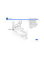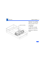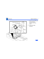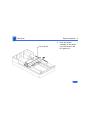
1
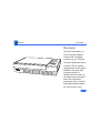
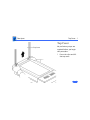
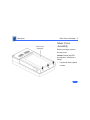
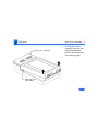
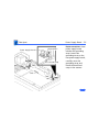
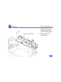
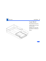
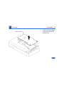
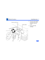
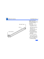
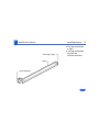
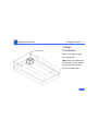
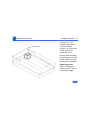
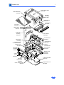
K Service Source
Apple Color OneScanner
K Service Source
Basics
Color OneScanner
Basics
Overview - 1
Overview
The Color OneScanner is a
24-bit one-pass flatbed
scanner with a scanning
resolution up to 1200 dpi.
The Color OneScanner uses a
tri-linear CCD to capture
eight bits each of red, green,
and blue in one pass. As a
one-pass scanner, it
samples all three colors at
the same time, resulting in
truer color and better
registration than a scanner
that makes separate passes
for each primary color.
Basics
Overview - 2
Features
The Color OneScanner offers
• Selectable 75- to 1200-dpi scanning resolution
• Scanning of documents up to 8.5 x 14 inches
• User-controlled scanning or Autoscan
• ColorSync color-matching software
• Compatibility with all Macintosh computers with 68020
processor or greater
K Service Source
Specifications
Color OneScanner
Specifications
Characteristics - 1
Characteristics
Scanner Type
Maximum
Document Size
Flatbed
8.5 by 14 in.
Speed
13 ms/line at 300 dpi
Grayscale
256 levels (8 bits per pixel)
Dropout Color
White
Interface
SCSI
Specifications
Electrical - 2
Electrical
Line Voltage
120 VAC ±10% (US and Canada)
100/120/200/220/240 VAC ± 10% (Universal)
Frequency
58–62 Hz (US and Canada)
48–62 Hz (Universal)
Specifications
Physical - 3
Physical
Size
Weight
Height: 4.3 in. (110 mm)
Width: 13.4 in. (340 mm)
Depth: 21.5 in. (545 mm)
23 lb. (10.45 kg)
Specifications
Environmental - 4
Environmental
Operating
Temperature
Storage
Temperature
Relative Humidity
50–104°F (10–40°C)
–40 to 117°F (–40 to 47°C)
20–95% noncondensing
K Service Source
Troubleshooting
Color OneScanner
Troubleshooting
General/ - 1
General
The Symptom Charts included in this chapter will help you
diagnose specific symptoms related to your product. Because cures
are listed on the charts in the order of most likely solution, try
the first cure first. Verify whether or not the product continues to
exhibit the symptom. If the symptom persists, try the next cure.
(Note: If you have replaced a module, reinstall the original module
before you proceed to the next cure.)
If you are not sure what the problem is, or if the Symptom Charts
do not resolve the problem, refer to the Flowchart for the product
family.
For additional assistance, contact Apple Technical Support.
Troubleshooting
Scanner Lamp Versions/ - 2
Scanner Lamp Versions
This procedure covers how to differentiate between 8-bit
(grayscale) and 24-bit (color) scanner lamps.
When a single error light is flashing, check to see whether the
lamp is giving off a green or white light.
• If the light has a green cast to it, an 8-bit lamp has incorrectly
been installed.
• If the light is bright white, the correct lamp is installed.
Proceed with the symptom charts.
Troubleshooting
Symptom Charts /LED Error Messages - 3
Symptom Charts
LED Error Messages
LED blinks once
1
2
3
4
LED blinks twice
1
2
3
4
5
Check to see if main lamp is giving off a green or white light.
If light is green, incorrect lamp is installed. Replace lamp.
Replace logic board.
Replace power supply.
Replace power supply cable.
Clean glass cover assembly.
Check lamp holder connector.
Check that label of fluorescent lamp faces down into lamp
holder.
Replace lamp.
Replace optical assembly.
Troubleshooting
Symptom Charts /LED Error Messages - 4
LED blinks three
times
1
2
3
4
5
6
Check motor carrier assembly.
Check drive belt assembly.
Check gears and pulleys.
Check limit switch assembly.
Check home position switch assembly.
Check carrier shaft; it should not be bent.
Power-on self-test
does not find error
(LED does not blink);
scanner is not
capturing image
correctly
Replace optical assembly.
Troubleshooting
Symptom Charts /Miscellaneous - 5
Miscellaneous
Power lamp not on;
machine dead
1
2
3
4
5
6
7
8
Plug in power cord.
Close lamp cover and turn button clockwise.
Check for correct setting of voltage selector (on
international models).
Check interlock switch with multimeter. Replace switch if it
is not opening and closing.
Check fuses FU1, FU2, and FU3 on power supply board.
Replace logic board.
Replace power supply.
Replace transformer.
Troubleshooting
Symptom Charts/Miscellaneous - 6
Optical assembly does
not move
1
2
3
4
5
Check SCSI connection.
Check SCSI ID.
Check and clean or replace belt.
Check belt tension. Belt should be tight with no slack.
Check for damage to gears or buildup of foreign material.
Clean or replace gears.
Optical assembly
moves once and then
does not move
1
2
3
4
Check limit switch for continuity.
Check drive belt.
Check drive belt pulleys.
Check carrier motor.
Troubleshooting
Symptom Charts/Miscellaneous - 7
Scanning program
crashes during
middle of scanning
operation, or
computer hangs
1
2
3
4
5
6
7
8
9
10
Verify version of scanner application software.
Verify that scanner driver is present.
Verify version of scanner driver.
Check SCSI connection.
Verify that host computer has enough memory.
Verify that system software is version 7.0 or above.
Verify SCSI ID of scanner.
Verify scanner SCSI termination.
Turn on scanner and reboot computer.
Replace logic board.
Fluorescent lamp
won’t light or is dim
1
2
Check lamp holder connector.
Check that label of fluorescent lamp faces down into lamp
holder.
Replace lamp.
Replace flexible cable.
Replace optical assembly.
Replace logic board.
3
4
5
6
Troubleshooting
Scan command does
not execute
Symptom Charts/Miscellaneous - 8
1
2
3
4
5
Check external cable connections.
Reset SCSI select switch on scanner to unused device number.
Scanner is factory-preset at 2. Do not use 7, 8, 9, or 0.
Check that SCSI cable terminates correctly.
Check fuse on logic board.
Replace logic board.
Image not clean; dark
or light spots
1
2
3
4
5
Clean glass with water and soft, lint-free cloth.
Adjust contrast or threshold settings on application.
Replace lamp.
Replace optical assembly.
Replace logic board.
Scanning performed,
but image doesn’t
reach host computer
1
2
3
4
Check interface connector.
Replace optical assembly.
Check fuse FU1 on logic board.
Replace logic board.
Troubleshooting
Incorrect image on
host screen
Symptom Charts /Miscellaneous - 9
1
2
Clean glass with water and soft, lint-free cloth.
Replace optical assembly.
K Service Source
Take Apart
Color OneScanner
Take Apart
Top Cover - 1
Top Cover
Top Cover
No preliminary steps are
required before you begin
this procedure.
1
Press the clips and lift
the top cover.
Take Apart
Glass Cover Assembly - 2
Glass Cover
Assembly
Glass Cover
Assembly
Before you begin, remove
the top cover.
Caution: Review the ESD
precautions in Bulletins/
Safety.
1
Loosen the three captive
screws.
Take Apart
Glass Cover Assembly - 3
2
Glass Cover Assembly
Retaining Clips
(both sides)
Lift the glass cover
assembly from the rear,
and at the same time
press in and release the
two retaining clips.
Take Apart
Glass Cover Assembly - 4
Glass Cover
Assembly
Start Scan
Board
3
4
Scan Switch Cable
Caution: When
removing the glass cover
assembly, make sure you
don’t damage the start
scan board.
Raise the glass cover
assembly to 90° and
disconnect the scan
switch cable from the
start scan board.
Remove the glass cover
assembly.
Take Apart
Glass Cover Assembly - 5
5
Start Scan
Board
Replacement Note:
Before returning a
damaged glass cover
assembly, remove the
start scan board. Install
the start scan board on
the new glass cover
assembly.
Take Apart
Optical Assembly - 6
Optical Assembly
Optical Assembly
Before you begin, remove
the following:
• Top cover
• Glass cover assembly
Caution: Review the ESD
precautions in Bulletins/
Safety.
Take Apart
Optical Assembly - 7
Retaining Screw
Lamp
Assembly
1
2
Pull the wire handle and
loosen the lamp
assembly retaining
screw.
Remove the lamp
assembly
Take Apart
Optical Assembly - 8
Front Plate
3
Remove the two
retaining screws and
lift out the front plate.
Replacement Note:
Place the screws in the
front plate before
reinstalling the plate in
the scanner. Carefully
lower the plate down and
tighten the screws.
Take Apart
Optical Assembly - 9
4
Left Guide Rail
Push the optical
assembly to the center
over the cutout in the
left guide rail.
Take Apart
Optical Assembly - 10
5
6
Ground Clip
Limit Switch Assembly
Remove the two
retaining screws, the
trigger arm, and the
ground clip.
Slide the limit switch
assembly to the side.
Take Apart
Optical Assembly - 11
7
Pulley Lever
Tension Lock Screw
8
9
Loosen the tension lock
screw.
Slide the pulley lever
forward to relieve belt
tension and remove the
belt from the rear
pulley gear.
Remove the belt from the
front pulley gear.
Take Apart
Optical Assembly - 12
Front Retaining Bracket
10 Remove the two
retaining screws and the
carrier shaft front
retaining bracket.
Take Apart
Optical Assembly - 13
Optical Assembly
11 Caution: Do not lift the
optical assembly too
high, or you may damage
the flex cable.
Lift the shaft until it
clears both support
brackets and pull the
shaft slightly to the
right.
12 Free the left side of the
optical assembly from
the left guide rail.
Take Apart
Optical Assembly - 14
13 Using a small flat-blade
screwdriver, disconnect
the flex cable.
Optical Assembly
Ferrite Bead
Flex Cable
14 Remove the cable from
the ferrite bead and the
optical assembly.
Take Apart
Optical Assembly - 15
15 Lift the optical block
from the scanner.
Carrier
Stopper
Sleeve
Carrier Shaft
Optical Block
16 Slide the carrier shaft
out of the optical block.
Note: Keep the carrier
stopper sleeve with the
shaft.
Take Apart
Optical Assembly - 16
Retaining Clip
17 Using a small
screwdriver, pry off
the retaining clip and
remove the belt from the
optical assembly.
Take Apart
Inverter Assembly - 17
Inverter Assembly
Inverter Assembly
Before you begin, remove
the following:
• Top cover
• Glass cover assembly
• Optical assembly
Caution: Review the ESD
precautions in Bulletins/
Safety.
.
Take Apart
Inverter Assembly - 18
Drive Belt
Note: You do not have to
remove the drive belt
from the optical block.
Take Apart
Inverter Assembly - 19
1
Optical Board
Cover
Using a flat-blade
screwdriver unlatch the
optical board cover.
Caution: Do not loosen
the two optical board
retaining screws.
Loosening the screw
damages the optical
alignment, and you must
replace the optical
assembly.
Take Apart
Inverter Assembly - 20
2
Optical
Board
3
CN1
4
5
Connector
Mounting
Plate
Inverter
Disconnect cable
connector CN1 from the
optical board.
Remove the two screws
and the inverter.
Slide the connector
mounting plate toward
the inverter.
Lift and remove the
plate.
Take Apart
Carrier Motor - 21
Carrier Motor
Before you begin, remove
the following:
• Top cover
• Glass cover assembly
• Optical assembly
Caution: Review the ESD
precautions in Bulletins/
Safety.
.
Carrier Motor
Take Apart
Carrier Motor - 22
1
2
Left Guide Rail
Remove the two
retaining screws and the
front inside cover.
Remove the three
mounting screws and the
left guide rail.
Take Apart
Carrier Motor - 23
3
Cable Retainer
Cable Connector
Motor Plate
4
5
Disconnect the cable
connector from the
power supply board.
Unhook the cable
retainer.
Remove the three
mounting screws and
lift out the motor plate.
Take Apart
Carrier Motor - 24
6
E-Clip
7
Front Gear Pulley
8
Remove the E-clip and
washer.
Slide the front gear
pulley up and off the
pulley spindle.
Remove the remaining
three motor mounting
screws and the carrier
motor.
Replacement Note:
Install the motor onto
the carrier assembly as
shown.
Carrier Motor
Take Apart
Transformer - 25
Transformer
Transformer
Before you begin, remove
the following:
• Top cover
• Glass cover assembly
• Optical assembly
• Carrier motor
Caution: Review the ESD
precautions in Bulletins/
Safety.
Take Apart
Transformer - 26
1
Plate Assembly
Remove the three
mounting screws and
lift out the plate
assembly.
Take Apart
Transformer - 27
2
AC Inlet Cover
AC Switch
Cover
3
4
CN5
Limit Switch Assembly
CN2
5
Remove the retaining
screw and slide the AC
inlet cover forward and
lift it out of the scanner.
Remove the AC switch
cover.
Using a small flat-blade
screwdriver, release the
retaining tabs and
disconnect connectors
CN2 and CN5 from the
power supply board.
Disconnect the cable
connector from the
limit switch assembly.
Take Apart
Transformer - 28
Ground Straps
6
Remove the three screws
and two ground straps.
Take Apart
Transformer - 29
7
Remove the two
remaining screws and
lift out the transformer.
Take Apart
Transformer - 30
Transformer Bracket
Transformer
8
Remove the two
mounting screws and
separate the
transformer from the
transformer bracket.
Take Apart
Transformer - 31
Transformer Bracket
Transformer
Power Select Switch
9
On universal
transformers only,
remove the two mounting
screws and separate the
power select switch
from the transformer
bracket.
Take Apart
Power Supply Board - 32
Power Supply Board
Power Supply
Board
Before you begin, remove
the following:
• Top cover
• Glass cover assembly
• Optical assembly
Caution: Review the ESD
precautions in Bulletins/
Safety.
Take Apart
Power Supply Board - 33
1
AC Inlet Cover
AC Switch
Cover
2
Remove the retaining
screw and slide the AC
inlet cover to the right
and out of the scanner.
Remove the AC switch
cover.
Take Apart
Power Supply Board - 34
3
Ground Strap Bracket
Left Guide Rail
4
Remove the three
mounting screws and the
left guide rail.
Remove the two
mounting screws and the
ground strap bracket.
Take Apart
Power Supply Board - 35
Power Supply Board
Ground Wire
5
Ground Strap
CN5
6
CN4
CN3
CN2
CN1
Disconnect the five
cable connectors from
the power supply board:
• CN1
• CN2
• CN3
• CN4
• CN5
Remove the retaining
screw and detach the
power supply board and
ground wire.
Take Apart
Power Supply Board - 36
Power Supply Board
Ground Wire
Ground Strap
CN5
CN4
CN3
CN2
CN1
Replacement Note: A new
power supply board
includes the grounding
strap. Loosen the
grounding screw on the
new power supply board,
carefully move the
grounding strap, and
install the board and
strap in the scanner.
Take Apart
Power Supply Board - 37
7
Power Supply Board
8
Remove the three self–
threading screws and
the two machine screws.
Remove the power
supply board.
Take Apart
Logic Board - 38
Logic Board
No preliminary steps are
required before you begin
this procedure.
Logic Board
Caution: Review the ESD
precautions in Bulletins/
Safety.
Take Apart
Bottom Cover
Logic Board - 39
1
Loosen the three captive
screws and remove the
bottom cover.
Take Apart
Logic Board - 40
2
Optical Cable
Caution: Do not let the
optical cable slide back
into the scanner. Tape it
to the chassis until you
can reinstall the logic
board.
Disconnect the four
cables from the logic
board.
Take Apart
Logic Board - 41
3
Remove the four
mounting screws, and
remove the logic board.
Caution: Do not remove
the metal case from the
logic board. You could
cause electrostatic
damage to the circuitry.
K Service Source
Additional Procedures
Color OneScanner
Additional Procedures
Screw
Switch Cover
Selecting Voltage (Intl. Only) - 1
Selecting Voltage
(Intl. Only)
No preliminary steps are
required before you begin
this procedure.
1
Remove the screw and
the switch cover.
Additional Procedures
Selecting Voltage (Intl. Only) - 2
2
Voltage Selector
Using a coin or a flatblade screwdriver,
rotate the voltage
selector to match the
incoming voltage.
Replacement Note: Make
sure you install the
appropriate fuse for the
new voltage setting.
Additional Procedures
Power Supply Fuse - 3
Power Supply
Fuse
FU3
FU2
FU1
No preliminary steps are
required before you begin
this procedure.
Caution: Review the ESD
precautions in Bulletins/
Safety.
Additional Procedures
Power Supply Fuse - 4
Left Guide Rail Housing
AC Switch Cover
Note: To access fuses
FU2 and FU3, lift the
center of the left guide
rail housing and remove
it from the left guide
rail.
To access fuse FU1,
push in the tabs and
remove the AC switch
cover.
Additional Procedures
Power Supply Fuse - 5
Remove fuses FU1, FU2
AND FU3.
Replacement Note: Use a
replacement fuse with the
correct rating. FU2 and FU3
are glass fuses, and FU1 is a
fire-rated ceramic fuse.
FU3
(3A)
AC Switch
Cover
FU2
(1A)
FU1
(2A)
Additional Procedures
Lamp Replacement - 6
Lamp
Replacement
No preliminary steps are
required before you begin
this procedure.
1
2
3
Lamp Lock Button
Lift the cover to the
vertical position.
Move the optical
assembly to the home
position by switching the
scanner on and then off.
Using a coin or flatblade screwdriver,
unscrew the lamp lock
button.
Additional Procedures
Lamp Replacement - 7
4
Retaining Screw
Wire Handle
5
Pull on the wire handle
and unscrew the lamp
assembly retaining
screw.
Remove the lamp
assembly.
Additional Procedures
Lamp Replacement - 8
6
Carefully push out the
lamp from the socket.
Additional Procedures
Lamp Replacement - 9
Retaining Flange
Lamp
Lamp Assembly
Replacement Note:
When replacing the lamp
and lamp assembly,
make sure
• The lamp is free of
fingerprints. Use a
soft cloth to wipe the
lamp prior to
inserting it into the
lamp assembly.
• The printing on the
lamp faces the lamp
assembly.
• The lamp assembly
seats securely in the
left retaining flanges.
• The wire handle is in
the down position.
Additional Procedures
Lamp Replacement - 10
Retaining Flange
Lamp
Lamp Assembly
• The lamp lock button
is tight.
• The lamp lock button
activates the
interlock switches.
Additional Procedures
Transformer
Voltage Conversion - 11
Voltage
Conversion
Before you begin, remove
the transformer.
Note: When you remove the
transformer, do not remove
the transformer bracket
from the transformer.
Additional Procedures
Transformer
Voltage Conversion - 12
To convert a 110 V
scanner (without the
universal voltage
selector) to a universal
model, remove the
transformer and
bracket plate assembly
and install the universal
model transformer and
bracket plate assembly.
Replacement Note:
Before switching on
scanner power, refer to
“Selecting Voltage.”
K Service Source
Exploded View
Color OneScanner
Exploded View
Scan Start Board
076-0592
1
Top Coverw/ Glass
949-0388
Lid Hinge
Assembly
076-0275
Cable Optical
922-0021
Top Cover
949-0390
Optical Assy
661-0739
Shaft, Carrier
699-0514
Front Plate
Assembly
922-0331
Transformer
Assembly
915-0038 110V
915-0039 100/240V
Interior Cover
949-0226
Drive Belt
Assembly
076-0323
Carrier
Motor
957-0037
Lamp Holder
983-0008
AC Inlet Cover
949-0214
Shield Plate (L)
922-1196
*Fuses
See Parts List
Power Supply
661-0738
Bottom Cover
Assembly
949-0391
Plate
Assembly,
Carrier Motor
922-0017
Logic Board 24Bit
661-0740
Cover, Voltage Select
922-0402
Logic Board Cover
948-0050