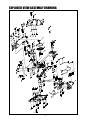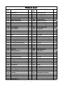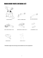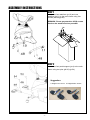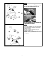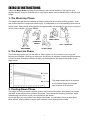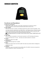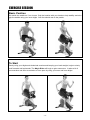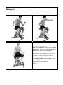
1
335/7729(D) MAGIC RIDER 1 http://www.body--sculpture.com CONTENTS IMPORTANT SAFETY INFORMATION 1 EXPLODED-VIEW ASSEMBLY DIAGRAM 2 PARTS LIST 3 MAGIC RIDER PARTS CHECKING LIST 4 ASSEMBLY 5 EXERCISE INSTRUCTIONS 7 EXERCISE COMPUTER 8 TROUBLE SHOOTING 9 EXERCISE SESSION 10 IMPORTANT SAFETY INFORMATION Please keep this manual in a safe place for easy reference. not use the equipment until the problem has been rectified. 1. It is important to read this entire manual before assembling and using the equipment. Safe and effective use can only be achieved if the equipment is assembled, maintained and used properly. It is your responsibility to ensure that all users of the equipment are informed of all warnings and precautions. 9. Wear suitable clothing while using the equipment. Avoid wearing loose clothing that may get caught in the equipment or that may restrict or prevent movement. 10. The equipment has been tested and certified to EN957 under class H.C. Suitable for home use only. Maximum weight of user is 100kg. 2. Before starting any exercise program you should consult your doctor to determine if you have any medical or physical conditions that could put your health and safety at risk, or prevent you from using the equipment properly. Your doctor's advice is essential if you are taking medication that affects your heart rate, blood pressure or cholesterol level. 11. The equipment is not suitable for therapeutic use. 12. Care must be taken when lifting or moving the equipment so as not to injure your back. Always use proper lifting techniques and/or seek assistance if necessary. 3. Be aware of your body's signals. Incorrect or excessive exercise can damage your health. Stop exercising if you experience any of the following symptoms: pain, tightness in your chest, irregular heartbeat, extreme shortness of breath, lightheadedness, dizziness, or feelings of nausea. If you do experience any of these conditions, you should consult your doctor before continuing with your exercise program. 4. Keep children and pets away from the equipment. The equipment is designed for adult use only. 5. Use the equipment on a solid, flat level surface with a protective cover for your floor or carpet. To ensure safety, the equipment should have at least 0.5 meters of free space all around it. 6. Before using the equipment, check that the nuts and bolts are securely tightened. 7. The safety of the equipment can only be maintained if it is regularly examined for damage and/or wear and tear. 8. Always use the equipment as indicated. If you find any defective components while assembling or checking the equipment, or if you hear any unusual noises coming from the equipment during use, stop immediately. Do -1- EXPLODED-VIEW ASSEMBLY DRAWING -2- PARTS LIST PART NO. 1. 2. 3. 4A. 5. 6. 7. 8. 9. 10. 11. 12. 13. 14. 15. 16. 17. 18. 19. 20. 21. 22. 23. 24. 25. 26. 27. 28. 29. 30. 31. 32. 33. 34. 35. 36. 37. 38. 39. 40. 41. 42. 43. DESCRIPTION Main frame Saddle support Pedal support Front pedal support Front connect tube Middle connect tube Rear connect tube Bearing Crank Front stabilizer Rear stabilizer Front handle bar Rear handle bar Axle Axle Fly wheel Computer support Bushing (φ25.4*φ10*8) Bushing (φ24*φ19*φ15*8) Bushing (φ24*φ19*φ12*8) Bushing (φ25.4*φ22.4*φ15*8) pedal axle Fly wheel axle Rear axle Washer (φ25.4*3) Bolt (φ10*83.5) Bolt (φ10*61.5) Bolt (φ10*51.5) Spring washer (φ17) Spring washer (φ12) Bearing Bearing Bolt (M6*60) Bolt (M6*82) Nut (M6) Nut (M10) Lock nut (M8) Screw (M8*20) End Cap Screw (M8*35) Bolt (M8*15) Bolt (M6*15) Screw (M6*16) QTY PART NO. 1 44. 45. 46. 47. 48. 49. 50. 51. 52. 53. 54. 55. 56. 57. 58. 59. 60. 61. 62. 63. 64. 65. 66L. 66R. 67. 68. 69. 70. 71. 72. 73. 74. 75. 76. 77. 78. 79. 80. 81. 82. 83. 84. 1 1 2 1 1 1 1 1 1 1 1 1 1 1 1 1 10 2 2 6 2 1 1 6 3 1 1 2 2 2 2 1 1 4 2 8 8 2 8 1 3 2 -3- DESCRIPTION Screw (ST4.2*25) Screw (ST4.2*5) Screw (ST4.2*10) Screw (M6*16) Screw (M8*40) Screw (ST4.2*25) Flat washer (φ8) Big flat washer (φ6) Curved washer (φ8) Spring washer (φ6) Pin (φ8*36) Belt (J6) Spring washer Rectangle end cap Belt wheel Rear pedal Front handle bar foam grip Rear handle bar foam grip Front pedal End cap QTY 4 6 4 2 6 8 11 2 8 2 2 1 1 1 1 2 1 1 2 2 Transport wheel 2 Saddle Left chain cover Right chain cover Front sleeve Rear sleeve Stabilizer end cap End cap End cap Computer Wire holder Sensor bracket Sensor wire Shelter Computer screw Magnetic Screwdriver Tool Adjustable foot cushion Nut Washer Washer 1 1 1 1 1 4 2 2 1 1 1 1 2 1 1 1 1 2 2 1 1 MAGIC RIDER PARTS CHECKING LIST MAIN FRAME*1 LEFT FRONT PEDAL SET*1 COMPUTER*1 FRONT STABILIZER*1 RIGHT FRONT PEDAL SET*1 REAR STABILIZER*1 REAR PEDAL SET*2 TOOL PACK*1 **Hardware might have already pre-assembled onto the components -4- ASSEMBLY INSTRUCTIONS STEP 1 Attach the front stabilizer (pt.10) and rear stabilizer (pt.11) to the main frame using four screws (M8*40)(pt.48). REMARK: Please pay attention 4PCS screws fixed on the wood board are parts#48. STEP 2 Attach the front pedal support (pt.4) to the main frame using two pins (φ8*36) (pt.54). Suggestion: a. Height over 151cm b.Height below 150cm -5- STEP 3 Attach the rear pedals (pt. 59) by screwing them into the corresponding crank arm. Note that the Right and Left pedal should be threaded on clockwise. STEP 4 Connect the computer wire with sensor wire (pt.75) and slide the computer down to the computer bracket. Then affix computer securely using the computer screw (pt.77). REMARK: Please pay attention screw fixed on the computer. -6- EXERCISE INSTRUCTIONS Using your Magic Rider regularly will provide you with several benefits. It will improve your physical fitness, tone your muscles and, in conjunction with a calorie-controlled diet, help you lose weight. 1. The Warm-Up Phase This stage helps get the blood flowing around the body and the muscles working properly. It will also reduce the risk of cramp and muscle injury. It is advisable to do a few stretching exercises as shown below. Each stretch should be held for approximately 30 seconds. Do not force or jerk your muscles into a stretch - if it hurts, STOP. INNER THIGH FORWARD BENDS SIDE BENDS CALF / ACHILLES OUTER THIGH 2. The Exercise Phase This is the stage where you put the effort in. After regular use, the muscles in your legs will become more flexible. Work at your own pace, but be sure to maintain a steady tempo throughout. The rate of work should be sufficient to raise your heartbeat into the target zone shown on the graph below. This stage should last for a minimum of 12 minutes though most people start at about 15-20 minutes. 3. Cooling-Down Phase This stage is to let your cardio-vascular system and muscles wind down. Slow down your tempo and work at this reduced level for about 5 minutes. Then repeat the stretching exercises, again remembering not to force or jerk your muscles into the stretch. As you get fitter you may need to train longer and harder. It is advisable to train at least three times a week, and if possible to space your workouts evenly throughout the week. 7 EXERCISE COMPUTER Functions and Operations Batteries Installation Please install 1 AAA 1.5V battery in the battery compartment on the back of counter. (Whenever battery is removed, all the functions values will be reset to zero.) Auto On/Off When the user starts to exercise, the Display will show the workout value automatically. Once user stops using the equipment for more than 256 sec, the Display will turn off. But the workout value of count/ total count /cal will remain. When user continues on with the exercises again, workout value of count/ total count /cal will accumulate continuously. ※By pressing the button for 2 seconds, all the function values except T-COUNT will be reset to zero. Auto Scan After the monitor is powered on or the button is pressed, the LCD will display all functions values from Time-Count- T-Count – Cal. Each value will be shown for 6 seconds. Count Displays the step from 0 to 9999. Total Count: Displays the total steps from 0 to 9999. Time Displays the workout time from 00:00 to 99:59. User also can press the button to display the workout time value. Calories Displays the calories consumption during training from 0.0 to 999.9. User also can press the button to display the calories consumption value. -8- TROUBLESHOOTING 1. Changing the battery. To change the computer battery, please slide the computer from the computer bracket, remove the battery cover and remove the battery. Replace with 1 x AAA battery. Finally put the cover back, and slide the computer back on the computer bracket. 2. Computer not working correctly. If your computer is not working correctly, please make sure the battery is installed correctly in the computer and that it is still working. -9- EXERCISE SESSION Basic Position Sit astride the saddle as if on a horse. Grip the handles with your hands to help stability and also grip the saddle using your inner thighs. Your feet should rest on the pedals. To Start Gently using your thighs and abdominal muscles and keeping your back straight, begin to slowly rock forwards and backwards. The Magic Rider will begin to gain momentum. It takes a bit of concentration and effort to maintain an even pace by using your torso and inner thighs. - 10 - Moving on Once you have gained confidence you may wish to ride with your thighs gripping the saddle more tightlly, allowing you to have your hands and arms free to increase the intensity of the ride. Another position Sitting ‘side saddle’ is another position that is worth trying , we only recommend this whilst holding quite firmly to the two handles. By doing so, this riding action tones the abs, strengthens the inner thighs and torso muscles and works the lumbar muscles. As the Magic Rider is self powered, you will be doing all the work yourself’, so you’ll benefit from a real workout !! Enjoy…………… - 11 - EXERCISE NOTES Use this space to record your own exercise routine results - 12 - Dimensions (L*W*H) 720 x 630 x 890 mm Batteries 1 x AAA Class Rating HC Maximum User Weight 100KG Please note that the specifications are subject to change without notice. Retailer: ARG Retailer address: 489-499 Avebury Boulevard Saxon Gate West Central Milton Keynes Bucks, MK9 2NW - 13 -