1
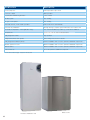
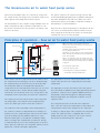
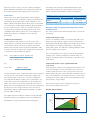
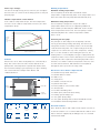
Technical and Specification Information
Greensource air to water
heat pump series
Greensource air to water
heat pump series
Worcester and you. Making a difference.
2
As part of the Bosch Group, Worcester
supported by an experienced technical
products are designed and manufactured to
services team which is able to provide
provide customers with the highest levels of
comprehensive support and advice
quality and reliability which are synonymous
from designing system layouts through
with the Bosch name throughout the world.
to installation.
As part of Europe’s largest supplier of
Worcester is dedicated to providing energy
heating products, Worcester, Bosch Group
efficient gas- and oil-fired condensing
has the UK-based resources and support
boilers, as well as an extensive range of
capability to offer you the value-added
renewable technologies. All of our products
solutions you deserve. Worcester employs
have been developed and introduced with
a nationwide network of Service Engineers
the aim of helping the UK to achieve the
and technically trained Field Sales Managers
Government’s efficiency targets.
The reception and main entrance
at our Worcester headquarters
Contents
Page
The Greensource air to water heat pump series
4-9
Renewable Heat Incentive (RHI) Scheme
10 - 11
Inside story – outdoor unit and technical data
12 - 13
Inside story – indoor unit and technical data
14 - 16
Is a heat pump suitable for the property?
17
Site preparations and guidance
18 - 19
energy efficient appliances in homes across
Installation and system design requirements
20 - 22
the UK. We will continue to invest in our
The Worcester Greenstar System Filter
23
products, people, facilities and added value
Frequently asked questions
24 - 25
“At Worcester we recognise the vital role you
play in the specification and installation of
services to ensure you have all you require
in order to deliver only the best solutions to
your customers’ requirements.”
Carl Arntzen,
Greensource air to water heat pumps
and accessories
26
Worcester training
27 - 29
After-sales
30
Managing Director,
Bosch Thermotechnology Ltd.
3
The Greensource air to water
heat pump series
Advanced renewable energy technology from
With this in mind, Worcester is proud to offer a range of G3
Worcester that’s leading the way to a greener and
compliant air to water heat pumps which allow the consumer
more sustainable future.
to take advantage of renewable and sustainable energy.
As part of the Bosch Group, Worcester is committed to
As well as being fuelled by the free and inexhaustible
environmental protection. Product development is prioritised
supply of latent energy, Worcester air source heat pumps
in the interests of people’s safety, the economical use of
offer additional advantages including simple and cost-
resources and environmental sustainability.
effective installation, suitability for a wide variety of
property types and sizes and, at a time when fuel costs
In just a few short years, Britain’s domestic heating
are rising, the chance to help your customers reduce
and hot water industry has changed dramatically.
their heating and hot water bills.
With approximately 25% of the UK’s carbon dioxide
Microgeneration Certification Scheme
emissions being produced by home energy consumption,
The Microgeneration Certification Scheme (MCS) is an
75% of which is for the provision of heating and hot water,
internationally recognised quality assurance scheme. It
such change has been not only inevitable but crucial.
certifies microgeneration technologies used to produce
electricity or heat from renewable sources. You must be
Words and expressions such as “renewable energy”,
an MCS certified installer to benefit from this scheme.
“sustainable technology” and “carbon footprint” have
become part of everyday conversation and have been
Worcester offers a MCS Made Easy programme to help you
fuelled by extreme weather and stark television images
prepare in readiness for a MCS accreditation assessment.
of melting polar ice caps.
For further information visit www.worcestermcs.co.uk
Worcester, Bosch Group has taken the lead in developing
Model
Certification no.
heating and hot water solutions which reduce the impact on
Greensource 6kW Outdoor Heat Pump and
Hot Water Distribution Unit
MCS HP0015/09
Greensource 7kW Outdoor Heat Pump and
Hot Water Distribution Unit
MCS HP0015/10
Greensource 9.5kW Outdoor Heat Pump and
Hot Water Distribution Unit
MCS HP0015/11
the environment by reducing harmful CO2 emissions, while
continuing to satisfy the daily demand for domestic heating
and hot water comfort – not only for today,
but well into the future.
4
How Greensource air to water heat pumps distribute heat
20ºC
22ºC
20ºC
Hot water to
baths, showers
and basins etc
22ºC
Hot water
distribution
unit
18ºC
Hot water piping
for radiators
Greensource
air to water
heat pump
Buffer
storage tank
20ºC
INDOOR
UNIT FEEDS
WARM WATER
TO UNDERFLOOR
HEATING AND/OR
OVERSIZED
RADIATORS
20ºC
OUTDOOR
UNIT
Underfloor heating
The Greensource air to water heat pump range at a glance
Outdoor unit
Indoor hot water distribution unit
6kW
7kW
9.5kW
Height
1,660mm
Height
1,223mm
1,223mm
1,223mm
Width
600mm
Width
818mm
818mm
818mm
Depth
615mm
Depth
643mm
643mm
643mm
144kg
152kg
Weight without
water
122kg
Weight
140kg
Weight with
water
347kg
Output of electric
electric heater
4.5kW
Galvanised powder coated steel
Outer casing
Emitted/supplied
output at
+7/35ºC**
5.5/1.5kW
7.2/2.2kW
8.4/2.5kW
CoP -7/35ºC**
2.0
2.3
2.3
CoP 2/35ºC**
3.2
2.8
3.0
CoP 7/35ºC**
3.7
3.3
3.4
Heat carrier flow
nominal (l/s)
0.19
0.29
0.34
x4
x4
x4
I.P. rating
DHW volume
151 litres
CH volume
55 litres
Power consumption
of circulation pump
Mains electrical
voltage
I.P. rating
0.2kW
1 x 230V N AC 50Hz
x4
*Without feet, additionally depending on the adjustment min. 20mm – max. 30mm.
**Output data according to EN 14511 European Standards.
CoPs are calculated using EN 14511.
See page 26 for Heat Pump Kits and part numbers.
5
Features
Benefits
Scroll compressor
Flow temperatures up to 65ºC
Low noise output
Quiet operation
2 years parts and labour guarantee*
Peace of mind
No flue system
Ease of siting
No gas or oil required
Ease of siting
Automatic defrost, -20ºC outside operation
Melts snow and ice automatically
Fast and easy installation
Through offering a complete system with indoor and outdoor unit
65°C water temperature – wide application range
More retrofit installations possible e.g. connection to radiators
Compact size
600mm2 internal hot water distribution unit
Fully integrated controls
Easy operation
Integrated stainless steel cylinder
Space saving and corrosion resistant
Fully integrated circulation pumps
Quicker installation and no need to purchase additional components
Built-in expansion vessels
Quicker installation and no need to purchase additional components
Diverter valves
Quicker installation and no need to purchase additional components
Inlet control set†
No need to purchase additional component
*Terms and conditions apply †Supplied in unvented kit
Hot water distribution unit
6
Outdoor unit
The Greensource air to water heat pump series
Worcester heat pumps make use of the latent energy from
The system comprises an external energy collector and
the outside air by converting it into heat which can be used
an internal Building Regulation G3 compliant heating and
with a typical wet heating and hot water system.
hot water distribution unit with a hot water store and
heat delivery system, preferably to underfloor heating or
The heat pumps use the constant energy available in the air
alternatively to oversized radiators.
with a refrigerant circuit to allow the temperatures to be
boosted to a useful level for the provision of heating or hot
Worcester air to water heat pumps are intended to be the
water for the home.
sole source of heating and hot water production for the
home, giving the homeowner the option of removing the
existing heat source from the property.
Principles of operation – how an air to water heat pump works
Note: The heating system should be designed to
maintain 70% of the nominal flow of the system across
the heat pump at all times.
Cold water
Hot water
(North facing wall)
Blending
valve***
Underfloor heating systems should have at least half of
the coils fully open at all times.
Hot water
Outdoor
sensor
Alternatively, or where TRVs are used, a by-pass may be
fitted. This must still maintain 40% of the nominal flow
across the heat pump.
Hot water
sensor
PLEASE NOTE
outside pipes should be
insulated class O standard.
Electric
element
3 way
valve
Where it is not possible, due to the design of the heat
emitters, to maintain this flow rate a Worcester primary
store of around 100 litres should be fitted. See diagram
on page 18.
Heating
water
Mixing
valve
Floor heating
Flow
sensor
45ºC
3 way
valve
*Recommended isolation valve
Isolation
valves*
Heating water
36ºC
Radiator
**Filter valve fitted on return
***A blending valve is supplied as standard
Filter valve
on return**
Air to water
heat pump
(Outdoor unit)
and should be fitted prior DHW outlet
Hot water
distribution unit
(Indoor unit)
Fan-assisted
convector
heaters
In the outdoor unit the refrigerant meets the outdoor air in
The drying filter is used to collect any moisture in the
the evaporator (heat exchanger). The air is drawn through
system. After the filter, the refrigerant passes through
the evaporator by a fan located on top of the heat pump.
a sight glass.
The refrigerant, which is in a liquid state absorbs free
energy from the air and evaporates in this process. A sensor
The sight glass is used to check the level in the system.
in the expansion valve ensures that the liquid refrigerant
There should be no bubbles in the sight glass during normal
collects the correct amount of the “free energy” before the
operations. However, there might be bubbles when the
refrigerant (now in a gas state) is led into the compressor.
heat pump is started and stopped or during defrosting.
After the sight glass, the refrigerant continues on to an
The compressor increases the pressure of the refrigerant.
expansion valve.
The temperature of the vapour reaches approximately
100°C. The warm gas is then led into the condenser.
The refrigerant pressure is lowered in the expansion
valve. This also causes the temperature to drop. When the
The condenser is the heat pump’s heat emitting part. In
refrigerant has left the valve and passes the evaporator
the condenser, which is a fully brazed heat exchanger in
it changes to vapour again. This completes the refrigerant
stainless steel, the refrigerant (gas state) meets the water
circuit. The expansion valve is equipped with a sensor
from the heating system (radiators and/or floor coils).
(bulb) just before the compressor. The sensor controls
When the warm gas is cooled by the circulating heating
the amount of fluid entering the evaporator.
water, it changes into a liquid state (condenses). Energy
is emitted in this process to the heating system or the hot
water. After the condenser, the refrigerant, which is now in
liquid form, continues through a drying filter.
7
Worcester offers a choice of 3 air to water heat pumps
The table below shows the relationship between flow
(6kW, 7kW and 9.5kW) which are intended to provide all
temperature and CoP. The CoP stated is for use only as
the heating and hot water requirements of the home.
typical examples and will differ between installations.
Performance
Relationship between flow temperature and CoP
Greensource air to water heat pumps feature a highly
efficient and effective scroll-type compressor which allows
around 65ºC flow temperature from the appliance. This
higher output temperature allows Greensource heat pumps
Heat delivery method
Typical CoP
Flow temperature
3
40 - 50ºC
4-5
30 - 40ºC
Radiators
Underfloor heating
to be effectively combined with radiators which should be
sized correctly. However, wherever possible, Worcester
Operation of the heat pump and heating and hot water
recommends an underfloor heating system as the most
distribution unit
compatible heat emitter system. The scroll compressor
The control unit uses two different methods to control the
allows Greensource heat pumps to offer excellent
heat pump.
CoP ratings.
Control with outdoor sensor
Coefficient of Performance
A sensor is installed outside on a north facing wall of the
The performance and efficiency of an air source heat
property. Control with an outdoor sensor means that the
pump system is commonly measured by the Coefficient
heat pump automatically regulates the heating in the house
of Performance (CoP). The CoP is a simple calculation
depending on the outdoor temperature. If the outdoor
which works out how much energy the heat pump is able
temperature drops, the underfloor heating/radiators inside
to extract from the energy source compared to the amount
the house will become warmer.
of electrical energy used by heat pump.
The user determines the response from the heat pump in
CoP =
Heat output of system (useful heat)
relation to the outdoor temperature, with the help of a
Electrical input from compressor
number of settings such as selecting the heat curve on the
and circulating pumps
control unit.
E.g.:
Control with outdoor sensor supplemented with
room sensor
CoP of 3.3 =
9kW heat pump
2.7kW of electrical input
Control with an outdoor sensor supplemented with a room
sensor means that a sensor can be placed in a reference
position inside the house. This is connected to the heat
The CoP depends on the temperature that can be extracted
pump and provides the control unit with information about
from the outdoor unit and the temperature required by
the room temperature. The signals affect the control unit’s
the heating system of the house. The best combination
settings (heat curves) and ensure the heat pump gives the
for a high CoP would be a higher source temperature (e.g.
best possible energy savings.
10ºC) and a lower flow temperature for the heating (e.g.
35ºC). The return on the energy employed in this case is
The heat curve slope can be changed to increase or
higher since the heat pump has to increase the temperature
decrease the heating in the house.
by only 25ºC. If the energy from the source is lower in
temperature and the required flow temperature is higher
Emitted output air/water
the CoP will be reduced.
10
The equation shown results in 2.7kW of heat provided by
8
the pump (which is provided by electrical consumption)
and 6.3kW of energy extracted from the atmosphere.
Emitted
output
(kW)
Air/water 7kW
6
Electricity
4
Heat pump
2
20
15
10
5
0
-5
-10
Outdoor temperature (ºC)
8
-15
-20
-25
Curve slope settings:
Working temperatures
The unit is already factory preset, however you can adjust
Maximum working temperatures
the heat curve to a level for the heating system to suit your
The heat pump can work with a maximum return
property type.
temperature of approximately 59°C. If the temperature rises
above this value the heat pump will automatically stop.
Weather compensation control method
If the outdoor temperature drops, the flow temperature
Minimum working temperatures
increases. If the outdoor temperature increases, the flow
The heat pump is designed to stop if the outdoor
temperature drops.
temperature falls below -20°C. Supporting additional
heat could be produced by the additional elective heater
from temperatures below -3ºC. The heat pump re-starts
automatically when the outdoor temperature climbs
65
60
55
Heating
system
flow
temperature
(ºC)
50
Ele
45
ctr
i
he
cal
Heat
above -20°C.
r
ate
p
pum
Defrosting the heat pump
ºC
/45
55
ºC
8/32
tem
em 3
Sys
Syst
40
35
The principle of defrosting in the heat pump is known
as hot gas defrosting. During defrosting, the flow in the
refrigerant circuit is reversed by means of an electrically-
30
25
controlled four-way valve. The compressed gas from the
20
15
10
5
0
-5
-10
-15
-20
-25
Outdoor temperature (ºC)
compressor is fed into the top of the evaporator, causing
the ice on the outside to melt. During this process, the
heating water is cooled slightly. Hot gas is sprayed into the
Heat curve
evaporator and a sensor ensures that the process functions
Controls
correctly. The time required for defrosting depends on the
Greensource air to water heat pumps are controlled by a
amount of ice and the outdoor temperature. This also acts
Rego 800 control unit. The unit ensures that the heat
as a fan defrost function, which blows hot air upwards
pump works efficiently when required and dictates that
through the fan to prevent it freezing solid.
the hot water heating is given priority over space heating.
The control unit has a simple main “Menu” and
Greensource air to water components list
“Advanced Menu”.
1 x tundish factory fitted 22mm x 1"
1 x tundish 15mm x 22mm
4 x rubber feet
ON/OFF LED
1 x circlip pliers
2 x flexible connection hoses
1 x particle filter valve
Menu
window
Menu dial
2 x indoor/outdoor sensors with cable
1 x unvented kit
1 x hot water blending valve
Switch
(ON/OFF)
1 x 32mm (1¼") universal waste fitting
1 x heating system filling loop
1 x user guide (heat pump)
1 x user guide (heating and hot water distribution unit)
1 x installation manual and guarantee card
Electrical isolation
Compressor
Fan
Electrical
heater
Hot water mode
Hot water peak
Note: Both the indoor and outdoor units require a means of
electrical isolation. It is recommended that the outdoor and
indoor units are supplied by an aM type fuse or a C and D
characteristic McB.
Extra hot water
Heating
system mode
Alarm
Holiday mode
Greensource air to water heat pump control panel
9
Renewable Heat Incentive (RHI) Scheme
for Domestic Properties
Overview
Who is eligible?
The Renewable Heat Incentive (RHI) scheme for industry,
The domestic RHI scheme applies to both off-grid and
business and the public sector was introduced by the
on-grid properties in England, Scotland and Wales.
Government in November 2011 as part of its commitment
to reduce the country’s carbon emissions by 20% by 2020.
The scheme covers single domestic dwellings and is open
to owner-occupiers, private landlords, registered providers
The scheme is now extended to domestic users who
of social housing, third party owners of heating systems and
are able to generate and use renewable energy to heat
self-builders.
their properties.
The scheme is open to all of the previous who have
This provides installers with an opportunity to inform
had applicable renewable technologies installed since
homeowners of the RHI scheme and the money they can
15th July 2009. However, applications will be dealt with
expect to receive by switching, even in part, to approved
on a phased basis over a period of time by the scheme
renewable energy sources instead of using fossil fuels.
administrator, Ofgem.
Who isn’t eligible?
Housing developers are excluded from the scheme although
it is possible that they could be eligible under the existing
non-domestic scheme.
10
Tariffs
When discussing the RHI scheme with your customers, the
first question you’ll probably be asked is “how much will I
get and for how long?”
What criteria are required to
apply for the scheme?
Training
All installations must be carried out by an MCS approved
Tariffs have been calculated by The Department of Energy
installer and meet the relevant standards for each
and Climate Change (DECC) and will change annually in-line
technology. Worcester runs MCS, Green Deal and individual
with the previous year’s Retail Price Index.
renewables product courses at each of its training
All payments are made directly to the homeowner
academies. For further information visit
retrospectively every quarter over a period of seven years.
www.worcester-bosch.co.uk/training or call 0330 123 0166.
The tariffs are per kilowatt hour of renewable energy
Green Deal Assessment (GDA)
produced by each of the following technologies:
All applicants for the scheme, including those who have had
renewable technologies installed since 15th July 2009, will
Renewable product
Air Source Heat Pumps
Price per kWh
7.3p per kWh
LECP Ground Source Heat Pumps
18.8p per kWh
Solar thermal
19.2p per kWh
need to have a Green Deal assessment carried out on their
property to determine which renewable technologies are
the most cost-effective. Where recommended by the GDA,
properties must meet the energy efficiency requirements of
a minimum of 250mm of loft insulation together with cavity
wall insulation.
Heat pumps and solar tariffs can be jointly claimed
providing they are in the same property.
Energy Performance Certificates (EPC)
In situations where the loft and cavity wall insulation have
How will the payments
be calculated?
Air and ground source heat pumps
not been installed, the property’s EPC will need to be
updated when the work has been carried out. In properties
where installation is not feasible, an EPC will also be
required as proof.
The amount of renewable energy qualifying for payment
The only exception is for self-builders whose properties
is based on a deemed estimate of the heat demand from
will meet Building Regulation requirements for energy
the property’s Energy Performance Certificate (EPC). This
efficiency and will therefore already qualify for the scheme.
is combined with an estimate of a heat pump’s efficiency
They will, however, require an EPC to enable Ofgem to
minus the energy required to run it.
calculate payments.
Solar thermal
The amount of renewable energy qualifying for payment
is based on a deemed estimate of the solar thermal
performance completed as part of a Microgeneration
Certification Scheme (MCS) installation.
Metering and monitoring incentive
Heat pump installations should be meter-ready wherever
possible. To help improve the performance of renewable
heating systems, there is an additional incentive for
selected properties to have metering and monitoring service
packages installed. For heat pumps this is £230 a year.
Space heating
Applications for space heating systems where there is
already a back-up fossil-fuelled heating system in place, for
example with a gas-fired condensing boiler, are required to
install metering systems on which their RHI payments will
be based. This also includes hybrid systems.
Payments for energy from renewable products
to householders will be made until 2021.
Please note: Renewable Heat Premium Payments or other public funds previously claimed
for a system will be deducted from RHI payments.
11
Inside story – Greensource heat pump
outdoor unit
Low pressure switch
Manual air vent
Four-way valve
Sight glass
Condenser
Expansion valve
Non-return valve
Drying filter
High pressure switch
Service connection
Service
connection
Compressor
12
Technical data –
Greensource air to water heat pump outdoor unit
Output
6kW
7kW
9.5kW
Height
1,223mm
1,223mm
1,223mm
Width
818mm
818mm
818mm
Depth
643mm
643mm
643mm
Weight
140kg
144kg
152kg
Galvanised powder coated steel
Galvanised powder coated steel
Galvanised powder coated steel
Emitted/supplied output at +7/35ºC
5.5/1.5
7.2/2.2
8.4/2.5
Heat output / CoP -7/35ºC1
Outer casing
2.8/2.0
5.0/2.3
5.6/2.3
2/35ºC1
4.6/3.2
6.1/2.8
7.1/3.0
Heat output / CoP 7/35ºC1
5.5/3.7
7.2/3.3
8.4/3.4
Heating system flow nominal
0.19 l/s
0.29 l/s
0.34 l/s
5kPa
6kPa
7kPa
2,200m3/h
2,200m3/h
2,200m3/h
0.44A
0.44A
0.44A
16
25
25
23.43A
30.56A
32.05A
230V 1N ~ 50Hz
230V 1N ~ 50Hz
230V 1N ~ 50Hz
Scroll
Scroll
Scroll
FV 50S
FV 50S
FV 50S
Maximum outgoing flow temperature
65ºC
65ºC
65ºC
Refrigerant filling R-407C
2.5kg
2.6kg
2.95kg
Hot gas with four-way valve
Hot gas with four-way valve
Hot gas with four-way valve
-20 to +35ºC
-20 to +35ºC
-20 to +35ºC
Hose 1" internal thread
Hose 1" internal thread
Hose 1" internal thread
65dB(A)
65dB(A)
65dB(A)
53dB(A)
53dB(A)
53dB(A)
x4
x4
x4
Heat output / CoP
Internal pressure drop heat carrier
Air flow
Electrical consumption fan
Fuse size – Amperes time delay4
Starting current – softstart
Electrical supply
Compressor
Compressor oil
Defrost system
Operating temperature5
HTF connection, clamping ring (mm)
Sound power
level2
(dB(A))
Sound pressure level3
I.P. rating
* Without feet, additionally depending on the adjustment min. 20mm – max. 30mm.
1 Output data at +7/35ºC, +7/45ºC are stated according to the European Standard EN 14511.
2 Calculated value at 1m distance according to EN ISO 3743-2.
3 Calculated value at 1m distance according to EN ISO 11203.
4 aM type fuse, C characteristic McB.
5 Tested at -17ºC according to the European standard EN 14511-4.
CoPs are calculated using EN 14511.
13
Inside story – Greensource heating
and hot water distribution unit
Temperature
and pressure
relief valves
(factory fitted)
System pressure
relief valve
(factory fitted)
REGO 800
control panel
Mixing valve
Pressure gauge
Drain valve
Three-way valve
(hot water)
14
Heat carrier
pump (G2)
Pump for heating
system (G1)
Non-return valve
Three-way valve
(heating)
G3 unvented kit includes a filling loop, blending valve, a 19 litre expansion vessel and hose,
inlet control set, 15mm x 22mm tundish and waste coupler is supplied with each unit.
Technical data –
Greensource indoor hot water distribution unit
Model
Greensource heating and hot water distribution unit
Height
1,660mm
Width
600mm
Depth
615mm
Weight without water
122kg
Weight with water
347kg
Output of electric heater
4.5kW
Power consumption of circulation pump
0.2kW
230V IN - 50Hz AC
Mains electrical voltage
25A
Fuse rating**
Maximal power consumption
4.7kW
Maximum working pressure
2.5bar (0.25MPa)
Volume DHW cylinder/Primary water
Recovery time for cylinder
151/55 litres
Full volume from 15ºC to 55ºC
2hrs 15mins
70% volume from 15ºC to 55ºC
1hr 50mins
Expansion vessel size
12 litres
Pump for the heating system G1
Wilo Star RS 25/6-3
Heating fluid pump G2
Wilo Star RS 25/6-3
* Without feet, additionally depending on the adjustment min. 20mm – max. 30mm.
** aM type fuse D characteristic type McB means of electrical isolation required.
15
Heat pump data
Heat pump system
Greensource air to water
heat pump 6kW
Greensource air to water
heat pump 7kW
Greensource air to water
heat pump 9.5kW
50A
63A
63A
BS EN 61000-3-11
BS EN 61000-3-11
BS EN 61000-3-11
–
–
BS EN 61000-3-3
BS EN 61000-3-12
BS EN 61000-3-12
BS EN 61000-3-12
3 x 3kW
3 x 3kW
3 x 3kW
20 min ramp up 0 - 100%
20 min ramp up 0 - 100%
20 min ramp up 0 - 100%
Greensource air to water
heat pump 6kW
Greensource air to water
heat pump 7kW
Greensource air to water
heat pump 9.5kW
Rating or aggregate rating
1.94kW
1.94kW
2.99kW
Maximum starting current
22.9A
23.8A
30.9A
30mins
30mins
30mins
Electronic soft start
Electronic soft start
Electronic soft start
0.30
0.30
0.30
Greensource air to water
heat pump 6kW
Greensource air to water
heat pump 7kW
Greensource air to water
heat pump 9.5kW
4.5kW
4.5kW
4.5kW
1.5kW x 3
1.5kW x 3
1.5kW x 3
20 min ramp up 0 - 100%
20 min ramp up 0 - 100%
20 min ramp up 0 - 100%
Model
Rating or aggregate rating
Standard compliance
Complies with technical requirements
Harmonics standard compliance
Stages
Time delay between stages
Heat pump compressor
Model
Minimum time between starts
Compressor method of starting
Starting power factor
Additional heating elements
Model
Aggregate rating
Stages
Time delay between stages
16
Is a heat pump suitable for the property?
It is essential that heat pump systems are designed to
In existing properties, boilers are often oversized and
operate efficiently in order to meet the heating needs of
should therefore not be used to determine the actual heat
the building, and the expectations of the customer. In order
requirements of the house.
to achieve this, the following design activities must be
completed prior to the installation:–
However, estimates may be made on the basis of the
• Pre-design assessment
existing energy consumption of the space to be heated.
Determine the suitability of a heat pump system for
•
the building based on the customer's requirements,
This brochure does not cover all the necessary details
expectations and building type.
to calculate the heat loss. The information given here
Detailed design
is provided to remind the heating system designer and
Complete building heat loss calculations and domestic
installer of the process and considerations.
hot water usage assessment.
• Specification
Worcester design service
Select a suitable heat pump and system components
Worcester’s design team offers design support across all
based on the detailed design. Calculate and communicate
of the Worcester, Bosch Group product range. The
the predicted energy use and running costs of the system
design team produces technical drawings and provides
to the customer.
specification advice for a range of customers; all of our
team are authorised SAP assessors and hold an
The total heat loss of the property (or building) is
provides a range of indemnified design solutions
calculated from the addition of fabric and ventilation heat
in support of our core range of Greenstar gas-
losses. Fabric heat loss is the transmission of heat by
and oil-fired boilers, Greenfloor heating and a
conduction through the building structure, i.e. windows,
growing portfolio of renewable technologies – including
walls, roof and floor. Ventilation heat loss is heated air
Greenskies solar thermal panels as well as Greenstore
escaping from the house which is replaced by cold air from
ground source and Greensource air source heat pumps.
D H E
INS
T
I
1964
E
S
ER
FD
TE O OMEST
I
ITU
IDHEE Domestic Heating Certificate. Worcester
TAL ENG
INE
MEN
ON
NG & EN
EATI
VIR
CH
Heat loss
the outside.
Calculating the heat loss of the property
It is essential to accurately calculate the heat loss of
the property to ensure correct sizing of the heat pump
system. The heat loss is dependent on the construction
of the building, room sizes, external and internal design
temperatures and air change rates. The heat loss
calculations should satisfy the requirements of
BS EN 12831.
Estimating heat loss
Estimating the heat loss of the building is useful in
determining the suitability of a heat pump system.
The design service for Worcester Greensource air to water
2
However, assumptions based on floor area (e.g. 50 W/m
heat pumps includes calculations for:
for new build etc.) and SAP (the Government's Standard
•
•
•
Assessment Procedure) should not be used for the detailed
design and specification stage. It should be noted that the
Heat pump sizing
Estimated annual running costs
Fact sheets.
heat loss for non-standard houses i.e. houses with large
areas of glazing, high ceilings, log burners etc. or houses in
For more information on the suitability of heat pumps
exposed locations may deviate significantly from any rules
for your home visit www.worcester-bosch.co.uk
of thumb.
For information and guidance on planning
permission for air to water heat pumps visit
www.energysavingtrust.org.uk
17
Site preparations and guidance
Heat pump installations should be made in accordance to
Installation clearances
the current MIS3005 micro generation installation standards,
Min.
1,500mm
including MCS020 planning standards.
Min.
300mm
Min.
1,000mm
Siting of the outdoor unit
Wall
Min.
500mm
The heat pump is located outdoors and contains a number
of sensitive parts. It is important that it is stood on a flat,
solid base, e.g. concrete slabs*. The heat pump should be
positioned at least 300mm from the building into which it
connects with the internal heating and hot water distribution
unit. The internal heating and hot water distribution unit
should be located as close as possible to the heat pump and
the outdoor connecting pipes should be suitably insulated
with Class O insulation to prevent freezing and the fluid
Outdoor unit clearances
Minimum distance from pump to wall
300mm
Minimum distance in front of pump
dosed with inhibitor and antifreeze.
1,000mm
Minimum distance to the side
The heat pump will produce between 15 - 25 litres of
500mm
Minimum distance above
1,500mm
condensation per day, depending on external temperatures,
The outdoor unit must be installed at least 2,000mm below
and this should be diverted to a mains drain or a soak away.
a roof to avoid the recirculation of cold air.
In order to prevent freezing the condensate pipe must be
insulated and the drainage pipe must slope towards a drain.
Outdoor unit casing dimensions and pipework connections
Side
Front
The outdoor heat pump can be sited up to 15 metres from
the property using 19mm thick Class O pre-insulated plastic
pipe available from:
Watts Industries UK Ltd,
Grosvenor Business Park,
1,223mm
Evesham,
Worcestershire WR11 1GA
Tel: 01386 446997
60mm
818mm
643mm
Back
Condensate drain
Electrical cable entry
Flow to indoor unit
201
165
101
Return from indoor unit
105
220
411
The flow is connected to the inlet marked ‘forward flow’.
The following connections are made to the heat pump:
A 32mm plastic pipe is taken from the drainage pipe to
the drain.
18
*Rubber matting can be used directly under the heat pump as a sound proofing method if required.
Siting of the heating and hot water distribution unit
Hot water distribution connection layout
29.50
Installation clearances
A minimum of 600mm is required in front of the unit. The
Top view
other sides can be blocked. A minimum of 25mm is required
between the unit and other permanent installations e.g.
558
walls, sinks, etc.
DHW
Expansion
vessel
Front view
Inlet control set
Min. 25mm
Min. 600mm
Wall
Front
Heating and
hot water
distribution
unit
Insulated
wall
The inlet control set
supplied should be
mounted externally in line
with G3 regulations.
Min. space 1,240mm
Connection area seen from behind
Return to
heat pump
Heat pump
top connection
Heating system
top connection
Heating and hot water distribution unit
pipework connections
The return is connected to the inlet marked ‘return flow’.
Flow from
heat pump
Cold water and hot water are connected to inlets marked
Heating system return
Heating system flow
Cold mains in
Hot water out (taps)
‘cold water’ and ‘hot water’.
The unit can be connected either from the top or from the rear connections.
Pipework dimensions
Heating and hot water distribution unit pipework dimensions
dirt before it can enter the heat pump. Accordingly, the
Heating flow and return
Connection size
22mm dia.
22mm dia.
22mm dia. (in HWDU)
Floor preparation
To indoor unit
Connection size
28mm dia. (in heat pump)
The appliance is designed to be free standing and should
be located on a flat surface which is able to support the
From heat pump
Waste water/drainage
It should be fitted as close to the heat pump as possible
and be horizontal.
To/from connections
Connection size
supplied particle filter valve should always be fitted on the
return pipe between the indoor and outdoor unit.
Hot and cold water
Connection size
The purpose of the particle filter valve is to filter out
32mm dia. (in both)
weight of the product, accessories and fluid content. The
appliance has rubber feet which can be adjusted to
All connections must be made using the sizes listed above.
suit the installation.
19
Installation requirements
System design requirements
The heating system should be designed to maintain 70%
Alternatively, or where TRVs are used a by-pass may be
of the nominal flow of the system across the heat pump
fitted. This must still maintain 40% of the nominal flow
at all times.
across the heat pump.
Underfloor heating systems should have at least half of the
Where it is not possible, due to the design of the heat
coils fully open at all times.
emitters, to maintain this flow rate a Worcester primary
store of around 100 litres should be fitted.
Expansion
vessel
(North facing wall)
Heating system return
Heating system flow
Air
temperature
sensor
Circulation pump
Wall
Heating and
hot water
distribution
unit
Isolation
valves*
Primary
store
Heating system return
Heating system flow
Flow
Heat pump
PLEASE NOTE
outside pipes
should be insulated
class O standard.
Hot water out (taps)
Cold mains in
Return
Blending
valve***
Filter valve
on return**
*Recommended isolation valve **Filter valve fitted on return ***Blending valve fitted to DHW pipe
System layout
Connecting the heat pump to the heating system
The heat pump is a part of the heating system. Faults in
Care should be taken to avoid excessive use of flux on
the heat pump can be caused by poor water quality in the
copper pipe connections to minimise the amount of debris
radiators or underfloor coils or because air is penetrating
and blocking of the filter.
the system continuously. Oxygen causes corrosion products
in the form of magnetite and sediment. This is detrimental
System flushing and care
to the heat pump components and reduces their working
Central heating systems must be flushed before the heat
life. Existing heating systems which require regular filling or
pump is installed. The system should be prepared in
where the heating water is not clear when drained, require
accordance with the guidelines of BS 7593 : 2006.
cleaning and flushing before the installation of a heat pump,
for example the heating system must be fitted with filters
The filter on the primary circuit should be checked
and vents.
during the first week of operation to ensure that any
debris is removed.
Heat pump sizing
Although the sizing of the heat pump can only be accurately
It is important that all previously mentioned preparations
carried out by taking all factors into consideration, this
have been carried out before the heat pump is connected
section offers some explanation of the principles behind the
to the heating system. Also ensure the pipe system has
sizing of heat pump according to the energy requirement of
been well flushed before it is connected to the heat pump.
the property.
Flushing protects the heat pump from contamination.
20
The following examples are for demonstration purposes only:
Maintenance on the outdoor heat pump
The outdoor heat pump unit should be checked regularly
An air source heat pump is typically sized to provide around
for leaves and debris, especially on the evaporation fins and
85% of the peak load of the house on the coldest day. Since
water tray. These must only be cleaned using a watering can
the number of days in a year that this requirement occurs
with a rose and a soft cloth to prevent damage.
is relatively low, the heat pump is typically sized to provide
95% of the total heating requirement for a property over
Maintenance on the indoor unit
the year. The remaining energy is provided by the built-in
This should be serviced annually in accordance with G3
electrical heater.
requirements.
The benefit of sizing the heat pumps below the peak load
Spare parts
requirement is that the pump, for the majority of the year, is
Only genuine Worcester, Bosch Group spare parts can be
able to remain on and deliver a ‘trickle charge’ of heat to the
used with these products.
property, rather than being oversized and constantly cycling
in and out of operation. This helps the heat pump to offer
Standards
better efficiency.
The installation of the Worcester Greensource air to water
heat pump system must be carried out in accordance
There are significant climatic differences across the UK and
with the relevant requirements for safety, current Wiring
this should be taken into consideration when sizing the
Regulations, local Building Regulations, Building Standards
heat pump. The Worcester system design service is able to
(Scotland), (Consolidation) Regulations and Bylaws of the
provide information on an individual basis.
local water company and Health and Safety document No.
63S (Electricity at Work Regulations 1989). It should be
For more information on the suitability of heat pumps for
in accordance with the relevant recommendations of the
your home visit www.worcester-bosch.co.uk
following British Standards and Regulations:
Communication cable
CoPs are calculated using EN 14511 which includes the
In the control unit the different circuit boards are connected
compressor and all pumps.
by a data communications cable (CANbus). This cable is
NOT SUPPLIED by Worcester, Bosch Group. A cable similar
BS EN 378
to CAT 5 E FTP 2 x 2 x 0.5 screened CANbus can be used.
Refrigerating systems and heat pumps. Safety and
environmental requirements.
CANbus cable must be a twisted pair, screened and earthed.
Maximum cable length is 20 metres. CANbus cables MUST
The Health and Safety at Work Act 1974
NOT be laid alongside power cables.
The Management of Health and Safety at Work
Warning: These connections must not be mixed up. If 12
Regulations 1999
volts are supplied on either CANL or CANH the processors
may result in damage. The four cables should be attached on
The Construction (Health, Safety and Welfare)
contacts with corresponding marking on the Greensource
Regulations 1996
air to water heat pump and the heating and hot water
distribution unit.
The Construction (Design and Management)
Regulations 1994
Dip switch S1
All CANbus pcbs should be connected in series and the dip
The Lifting Operations and Lifting Equipment Regulations
switch marks the beginning and the end of a CANbus net.
1998, and any other relevant regulations in force at this time.
Therefore, the dip switch on the HWDU display and on the
heat pump must be in the ‘TERM’ position. All others must
The manufacturer’s notes must not be taken in any way as
be in the opposite position (not terminated).
overriding statutory regulations.
Refrigerants
The Worcester Greensource air to water heat pump system
uses R407c pre-charged refrigerant.
21
System design requirements
The heating system should be designed to maintain 70% of
Filling the heating system with clean water
the nominal flow of the system across the heat pump at all
Worcester recommends the fitting of an in-line system filter
times. Underfloor heating systems should have at least half
to help ensure that the heating system can perform at its
of the underfloor coils fully open at all times.
optimum level.
• Set the pre-pressure for the expansion vessel in the
The heating system to which the heat pump is connected
must always have an uncontrolled volume of at least 25l,
otherwise a buffer tank (primary water storage) must
be installed.
premises according to the heating unit's static height
• Open the heating system's valves
• Top up the heating water in the system and fill system to
appropriate operating pressure
• Vent the heating system by opening the shut off valve.
System flushing and care
This may have to be repeated a couple of times and is
Flushing the system in line with BS 7593
very important to ensure the correct operation of the
• Fill the system with cold water and check for leaks
• Open all drain cocks and drain the system
• Close drain cocks and add a suitable flushing agent
heat pump
compatible with aluminium at the correct strength
for the system conditions and in accordance with the
manufacturer's instructions
• Circulate the flushing agent before the heat pump
is connected
•
•
•
(e.g. radiators)
• Refill to the correct pressure. Normal pressure is
1.0-2.5bar, but depends on the expansion vessel's
pre-pressure and the height of the building
• Shut the heating water filling valve when the correct
pressure is reached.
Run the system at normal operating temperature as
directed by the manufacturer of the flushing agent
Inhibitor
Drain and thoroughly flush the system to remove the
If the system is exposed to freezing conditions, add
flushing agent and debris
a suitable inhibitor or combined inhibitor/anti-freeze
It may be necessary to use a power flushing machine to
in accordance with the DWTA code of practice and
aid the cleansing procedure in some circumstances
manufacturer's guidelines.
• Close the drain cocks and refill with fresh water and a
suitable inhibitor
• Vent any air from the boiler and system
• Clean the particle filter.
The heating system must not contain more than
200ppm chlorine.
Filling the heating system
First flush the heating system. If the water heater is
connected to the system, it must be filled with clean water.
The heating system is then filled.
22
• Also bleed via the heating system's other bleed valves
The Worcester Greenstar
System Filter
Communication cable
The printed circuit boards in the Hydrolight/Hydrocomfort
unit, and accessories board if applicable, are connected
Modern heat pumps are precision engineered and designed
via the CANbus communication line. The CAN (Controller
to run with a clean water-heating system. Over time, dirty
Area Network) is a system that facilitates communication
system water will develop, damaging a heat pump and its
between microprocessor-based units/printed circuit boards.
components, causing failures, shortening the life of the
overall system and dramatically reducing the efficiency of
A room controller is available as an accessory and must
the heat pump.
be connected by a CANbus cable – also available as
an accessory.
A highly effective solution
The Worcester Greenstar System Filter has been specifically
Suitable cable for external laying is cable type LIYCY (TP)
designed to combat the damaging effects of system debris
2 x 2 x 0.5.
and pollutants, protecting the heat pump and heating
system for a fraction of its cost.
The cable must be twisted pair and screened. The screen
must only be earthed at one end and to the chassis.
At the centre of its innovative design is a powerful magnet
that removes the magnetic debris that is present in the
Maximum cable length is 30m between the internal room
heating system water. The central location of the magnet
controller and the internal Hydro unit.
ensures that the debris is collected quickly and retained.
Any non-magnetic debris is caught by the twin-action
The CANbus cable must not be routed together with
cyclonic trap, maximising overall protection.
the mains cable that carry 230V or 400V. The minimum
clearance is 100mm. Routing of these cables together with
the sensor cables is not permitted.
Greenstar System Filter features and benefits:
• Highly effective – safeguards the boiler against damage
and can save up to 6% a year on energy bills*
The connection between the circuit boards is by four wires,
• Prevents blockages in radiators – a warmer home and
quieter system
because the 12V supply between the circuit boards must
also be connected. The circuit boards have markings for
• Twin action – effective against magnetic and non-magnetic
both the 12V and CANbus connections.
system debris.
Refrigerants
NEW
The air to water heat pump is filled with R410A
refrigerant. It is therefore a requirement that the owner
of a Worcester Greensource Split Heat Pump has the
refrigerant circuit checked by a refrigerant engineer. Leak
tests must be performed at installation and then repeated
every 12 months.
Maintenance of the outdoor heat pump
The outdoor heat pump unit should be checked regularly
for leaves and debris, especially on the evaporation fins
and water tray. To prevent damage these must only be
cleaned using a watering can with a rose attachment and a
The filter can be fitted under or away from the heat pump.
Product info
Part number
soft cloth.
Maintenance on the indoor unit
7 716 192 609
This should be serviced annually. If a cylinder is fitted
this would have to be serviced annually in accordance
with G3 Building Regulations.
*Independent research.
23
Frequently asked questions
What benefits do air to water heat pumps offer over ground
source heat pumps?
There are significant benefits – lower installation costs –
no need to dig trenches or boreholes. The Greensource
• The air path to and from the unit must be checked to
ensure it is clear
• The heat pump water drain tray and the pipe to it must
be checked to ensure it is clear and clean.
air to water heat pump is a self contained unit that simply
needs connecting to the mains electricity supply and the
The technician should then turn the unit on and check that:
building’s wet heating system. They also take up much less
• the controls are operating properly
• the water pump is free and operating properly
• the unit’s fan is operating
• that the unit is increasing the water to the correct
space too as you don’t need a large area for the collector
trenches required for ground source heat pumps.
What refrigerant is used in Greensource air to water
operating temperature.
heat pumps?
Greensource air to water heat pumps use R407C. It is
How should the unit be sited to ensure the airflow
an approved refrigerant featuring zero Ozone Depleting
and access it needs?
Potential. It also has a low Global Warming Potential
What’s important is to ensure there is sufficient space for
which is more environmentally friendly.
airflow into the unit and enough clearance at the front of
the heat pump to stop cold air re-circulation. You’ll also
What is the lower limit operating temperature?
need to ensure that there is adequate space for access
The lower limit operating temperature of Greensource
for service and maintenance. You should try to ensure
air to water heat pumps is -20°C.
that the unit is sheltered from high winds as this will
improve the unit’s efficiency level by lowering the fan
What are the key maintenance requirements for
power requirement. The minimum clearances required
Greensource air to water heat pumps?
are shown on pages 18 and 19.
It will need servicing once a year by a qualified maintenance
technician. The technician will need to check a number of things
What size of cable should be used to connect the air to
during the service, including:
water heat pump to the mains electricity supply?
• A temperature pressure relief valve is fitted – in line with
Consideration should be given to the size of the unit,
G3 requirements for unvented cylinders
• Check the unit for signs of damage or corrosion
• Check the panels to ensure there is no vibration and that
they are properly fastened
•
All water connections must be checked for tightness or
signs of leakage and the system water pressure must
be checked
24
the length of the cable run and the type of cable being
used. Only have installation work carried out by qualified
technicians who will be able to calculate the correct
cable size for each installation.
What is the most efficient flow water temperature setting?
Is planning permission required for the installation of an
The lower the flow water temperature the less hard the
air to water heat pump?
heat pump has to work and the more efficient it will be.
Planning permission varies and is installation specific. For
It depends on the type of heating system the heat pump
information and guidance on planning permission for air to
is working alongside, but we recommend that the operating
water heat pumps visit www.energysavingtrust.org.uk
temperature for an underfloor heating system is 35°C and
for a typical radiator system is 50°C.
Can an air to water heat pump be used to cool the home
as well as providing heat?
What size of radiators should be used on installations
Our Greensource air to water heat pumps are designed to
linked to air to water heat pumps?
produce heating and hot water only. Greensource air to air
We recommend that radiators are appropriately sized based
heat pumps can cool the home as well as heating it.
on the heat loss of the home. Most radiator manufacturers
will supply selection tables and offer advice on this.
What guarantee is available?
Greensource air to water heat pumps come with a 2 year
Can you combine radiators and underfloor heating
manufacturer’s guarantee provided that the guarantee
when using an air to water heat pump?
is registered within 30 days of installation. For more
Yes you can. However, the heat pump return water
information please call 0330 123 2552.
temperature should be set for a radiator system at the
higher return temperature and a mixing valve should be
Is there a training course available?
fitted to reduce the water temperature for the underfloor
Yes, Worcester offers a range of training courses including
heating part of the system.
a 1 day Greensource Air to Water training course. Please
call 0330 123 0166 for more information.
Can the external air to water heat pump unit be hidden
behind bushes, trees and fences?
Yes, but you have to be aware that wherever you position
the unit it has to have adequate airflow available to it and
that the discharge air can’t be re-circulated back to the
inlet. If you don’t take enough care in this respect, it will
result in lowering the air temperature and can significantly
reduce the efficiency of the unit. Our recommended
clearances should be noted on page 18.
www.energysavingtrust.org.uk
25
Greensource air to water heat pump
range and accessories
Greensource 6kW Outdoor
Heat Pump and Hot Water
Distribution Unit*
Greensource 7kW Outdoor
Heat Pump and Hot Water
Distribution Unit*
Greensource 9.5kW
Outdoor Heat Pump and
Hot Water Distribution Unit*
120 litre
buffer storage
tank
Worcester Part No.
7 716 150 008
Worcester Part No.
7 716 150 009
Worcester Part No.
7 716 150 010
Worcester Part No.
8 718 544 081
Greenstar
system filter
Worcester Part No.
7 716 192 609
26
*Comes complete with 19 litre unvented kit.
The total training experience
Worcester expertise that will build your skills
Worcester has always placed great emphasis on technical
Mobile training
support and training for installers and service engineers.
To complement our training venues across the country,
Advances in heating technology, including the increasing use
we can also bring training to you.
of renewables, make the need for training greater than ever.
We have mobile vehicles fully equipped with operational
To ensure the highest levels of competence and expertise
Greenstar gas-fired boilers, dry strip-down models and even
in the installation of all Worcester products, we run
a Greensource air to air heat pump, ensuring that quality
intensive training courses for installers, commissioning
training in a comfortable environment can be achieved on
engineers and operatives involved with servicing and
your doorstep!
fault finding.
If it’s oil training you require, our 7.5 tonne mobile oil
Courses available
vehicle is available throughout the country for hands-on
Our training facilities offer a number of courses suitable
product training and OFTEC assessments.
for the installer and commissioning engineers, and more
in-depth courses for the servicing and fault finding engineers.
Distance learning/web based learning
Worcester has produced a selection of Distance Learning
Training centres throughout the UK
CD ROMs/DVDs which are packed with information.
To enable us to meet the growing demand for training we
Call 0330 123 9119 for your copies, or visit
have invested in additional facilities at the award-winning
www.worcester-bosch.co.uk for information
training academy at our Worcester headquarters. In addition
on Web Based Learning.
to the original academy there is now a new 400m2 unit, 25%
of which is devoted to an open-plan domestic training area
Get on course for a more profitable future now.
with life-size single-storey brick buildings. These feature
working Greenskies solar thermal systems which enable
Training centres
T
installers to get up onto the roof of the building to get more
College links
training centres
realistic training. There are bays full of all Greenstar gasfired appliances, so installers can really get to grips with
Elgin
the importance of system design. The additional space
also contains dedicated training areas for our renewable
and future products. The training centre also runs certified
Dundee
domestic and commercial ACS training and assessment.
Johnstone
Borders
Further academies are located at West Thurrock in Essex,
Ayr
Wakefield and Clay Cross in Derbyshire, all offering our full
Durham
suite of courses. Please phone 0330 123 0166 for more
Belfast
information about a course near you. Each course is run
by specialist trainers and is superbly equipped to deliver
a combination of classroom theory and practical hands-on
Burnley
W
Wakefield
Dublin
Clay Cross
experience that’s second to none.
Wrexham
Worcester
College-linked Learning
As well as offering training at our own centres, Worcester
Tredegar
has established close partnerships with many colleges
Cambridge
West Thurrock
Wiltshire
around the UK, equipping them with our latest products.
Call us on 0330 123 0166 to find out when we will be
Camborne
Paignton
running the course of your choice at a college in your area.
Call now for more information 0330 123 0166
27
Heat pump product courses
All academies allow customers to gain hands-on experience with our entire range of renewable products and inform
installers about the true benefits of installing heat pumps and underfloor heating. The introduction to heat pumps
course is designed for installers and heating engineers who have no experience in installing heat pumps. The various
one day heat pump courses are designed for those with more practical experience in heat pump technology.
Renewable courses
• Introduction to heat pumps.
• Greenstore LECP ground source heat pumps.
• Greensource split air to water heat pumps.
• Greensource air to water heat pumps.
• Greensource air to air heat pumps.
• Greenstar Plus Hybrid heat pumps.
• Renewable range overview.
Intro to
heat pumps
GSHP
Split AW
AWHP
AAHP
Hybrid
Renewable
Overview
Duration
1 Day
1 Day
1 Day
1 Day
1 Day
1 Day
1 Day
Cost
Free*
Free*
Free*
Free*
Free*
Free*
Free*
D
D
D
D
D
D
D
D
D
D
D
D
D
D
D
D
D
D
D
D
D
D
D
D
D
D
D
D
D
D
D
D
D
D
D
D
D
D
D
D
D
D
D
D
D
D
D
D
D
D
D
D
D
D
D
College Links†
D
D
D
D
D
D
D
D
D
D
D
D
D
D
D
Mobile†
U
U
U
U
D
D
D
D
D
D
U
U
Training course covers
Specification
Installation
Commissioning
Servicing
Maintenance
Product overview
System design
U
U
U
U
D
U
Course locations
Worcester
Clay Cross
Wakefield
West Thurrock
U
D
D
*A holding fee of £65 applies to free courses and is refunded on attendance of the course. If a booking is cancelled more than 10 working days before
the course date, the fee will be fully refunded. The fee is non-refundable if a cancellation is made less than 10 working days before the course date.
†Please contact Worcester Training for specific colleges and mobile dates.
To complement the above courses, Worcester also runs the Hot Water Systems and Safety course, IDHEE domestic
heating design, QCF Level 3 Award, MCS Made Easy and Green Deal courses. For more information turn to page 29.
Please note: it is recommended that unless you have experience installing/commissioning/servicing heat pumps or have worked previously
with heat pump technology, that the one day introduction to heat pumps course be attended before commencing with any specific heat
pump product courses.
28
Additional product and
industry training courses
The diversity of products in today’s heating industry gives
We are here to provide you with training and assistance for
you the opportunity to expand your expertise, whilst
all areas of your business, not just product training. Call us
offering more choice to your customers. Worcester
on 0330 123 0166 to order a full course training brochure
provides comprehensive training from all its academies
or to book yourself onto a training course, alternatively,
on its entire range of technologies.
you can visit www.worcester-bosch.co.uk/training
Gas-fired condensing boiler courses
Worcester commercial product courses
• Greenstar CDi Classic gas-fired condensing
• Greenspring CWi47 water heater.
• GB162 overview.
• GB162 domestic.
• GB162 commercial.
• Greenstar Heat Distribution Unit.
• Commercial ACS training and assessment – CODNCO1.
combi boilers.
• Greenstar CDi Compact and NEW Greenstar Si Compact
gas-fired condensing combi boilers.
• Greenstar i Junior gas-fired condensing combi boilers.
• Greenstar system & regular gas-fired condensing boilers
(covers NEW Greenstar 27Ri & 30Ri, Greenstar 12Ri-24Ri,
Greenstar CDi Classic Regular, Greenstar FS CDi Regular,
Bosch commercial product courses
Greenstar 30CDi Classic System, NEW Greenstar 27i &
• LPG Changeover.
• GB312 & GB402 overview.
• Solar thermal product overview.
• GWPL Gas Absorption Heat Pumps overview.
• CHP overview.
• Commercial controls overview.
Oil-fired product courses
Industry focused courses
•
• Oil advanced fault finding.
• OFTEC 50.
• OFTEC 101 & 105e.
• OFTEC 600a.
• OFTEC 101/105e/600a.
• Hot water systems & safety.
• Chemical water treatment.
• Construction skills F-Gas training/
Accessories training courses
•
30i System and Greenstar 12i-24i System boilers).
• Greenstar Highflow CDi & FS CDi Regular floor standing
gas-fired condensing combi and regular boilers.
Greenstar oil-fired products.
assessment certification.
• IDHEE domestic heating design.
• Domestic ACS training and assessment – reassessment.
CCN1 + 3 appliances.
• Worcester controls.
QCF Level 3 Award
– Air source and ground source heat pumps.
– Air to water and split air to water heat pumps.
– Solar thermal.
•
• Green Deal.
MCS Made Easy.
29
A complete after-sales service
As part of the worldwide Bosch Group, Worcester strives to
maintain the highest possible standards of after-sales care.
All the technical advice
you need
In addition to the no-nonsense parts and labour
Spares
guarantee applicable to all Worcester products, you and
Genuine replacement parts for all supported Worcester
your customers have the assurance that every Worcester
products are readily available from stock, or on a next day
product is manufactured to both the appropriate British
delivery basis. Visit our website www.worcester-bosch.
and European standards.
co.uk/spares to find your local stockist.
Worcester Contact Centre
Customer Technical Support
Should you require support, our award winning Contact
The Worcester Technical Helpline is a dedicated phone
Centre team, based at our head office in Worcester, are
line – committed to providing a comprehensive service to
ready to take your calls. Whatever your query our contact
complement the brand name and quality of our products.
centre operators along with our nationwide team of
Our experienced team of technical experts provides
engineers are ready to help you.
answers to queries of a technical nature across the entire
Worcester range.
Tel: 0330 123 9559
Worcester also has a pre-sales department, which provides
Opening times
assistance in selecting a heating system to suit a particular
Monday – Friday: 7.00am – 8.00pm
application, along with full guidance on installation. For
Saturday: 8.00am – 5.00pm
more information please contact the Technical Helpline
Sunday: 9.00am – 12 noon
or alternatively visit our website where literature can be
Bank Holidays: 8.00am – 4.30pm
downloaded www.worcester-bosch.co.uk
Technical
Tel: 0330 123 3366
Fax: 01905 752 741
Email: [email protected]
Opening times
Monday – Friday: 7.00am – 8.00pm
Saturday: 8.30am – 4.00pm
Bank Holidays: 8.00am – 4.30pm
30
Notes
31
Useful numbers
Customer Service
Sales
Engineer Appointments
Tel: 0330 123 9669
Email: [email protected]
Fax: 01905 456445
or telephone 0330 123 9339
[email protected]
Enquiries
Spare Parts
Email: [email protected]
Tel: 0330 123 9779
or telephone 0330 123 9559
Fax: 01905 754620
Guarantee Registration
[email protected]
To register your Worcester guarantee,
Technical Helpline (Pre & Post Sales)
please visit our website
Tel: 0330 123 3366
www.worcester-bosch.co.uk/registration
Fax: 01905 752741
or telephone 0330 123 2552
[email protected]
Renewables Technical Helpline
Email: [email protected]
or telephone 0330 123 9229
Training
Tel: 0330 123 0166
Fax: 01905 752535
[email protected]
Literature
Email: [email protected]
or download instantly from our website
or telephone 0330 123 9119
Calls to 03 numbers cost no more than a national rate call to an 01 or 02 number and must count towards any inclusive minutes in the same way as 01 and 02 calls.
These rules apply to calls from any type of line, including mobile, BT, other fixed phone line or payphone. Calls from mobiles and some other networks may vary.
Calls to and from Bosch Thermotechnology Ltd may be recorded for training and quality assurance purposes.
www.worcester-bosch.co.uk
In partnership with
This leaflet is accurate at the date of printing, but may be superseded and should be disregarded if specification and/or appearances
are changed in the interest of continued improvement. The statutory rights of the consumer are not affected.
Part No. 8 716 115 319 D 05/14
PAPERS MADE WITH
FREE
TM
100% CHLORINE
BLEACHED PULP
Worcester, Bosch Group,
Cotswold Way, Warndon,
Worcester, WR4 9SW
BBT3272
Worcester, Bosch Group is a brand name of Bosch Thermotechnology Ltd.