1
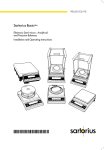
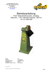
Summit Series
Operation Manual
SI-413
0 .0 0 0
T
PRIN
g
CAL/CF
N
CTIO
FUN
OFF
ON/
TARE
SI-12
4
T
PRIN
0 .0 0
N
CTIO
FUN
00
g
/CF
CAL
TARE
OFF
ON/
SI-6201
T
PRIN
0 .0
g
CAL/CF
N
CTIO
FUN
OFF
ON/
TARE
902535.1 Rev. A
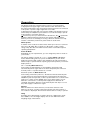
You have purchased a quality precision weighing instrument that
requires handling with care.
Read entire contents of this Operation Manual prior to operating
your new Denver Instrument balance.
Disclaimer
Calibrate your balance using a reference weight of the appropriate
tolerance (class). An instrument can be no more accurate than the
standard to which it has been compared. For assistance in the
selection of reference weights, please contact the factory.
!
Caution!
Changes or modifications not expressly approved by the
manufacturer could void the user’s authority to operate this
equipment.
!
Warning
Never lift balance by the weighing pan as this may cause
damage to internal mechanisms.
Always lift and transport the balance by its base, including
removal from packing materials!
Table of Contents
Specifications . . . . . . . . . . . . . . . . . . . . . . . . . . . . . . . . . . . . . . . . . . . . . . .ii
Getting Started . . . . . . . . . . . . . . . . . . . . . . . . . . . . . . . . . . . . . . . . . . . . . .1
Storage and Shipping Conditions . . . . . . . . . . . . . . . . . . . . . . . . . . . . .1
Pan Assembly . . . . . . . . . . . . . . . . . . . . . . . . . . . . . . . . . . . . . . . . . . . .2
Connection to AC Power . . . . . . . . . . . . . . . . . . . . . . . . . . . . . . . . . . . .3
Connecting to Peripheral Devices . . . . . . . . . . . . . . . . . . . . . . . . . . . . .3
Leveling the Balance . . . . . . . . . . . . . . . . . . . . . . . . . . . . . . . . . . . . . . .3
Operation . . . . . . . . . . . . . . . . . . . . . . . . . . . . . . . . . . . . . . . . . . . . . . . . . . .4
Warm-up Time . . . . . . . . . . . . . . . . . . . . . . . . . . . . . . . . . . . . . . . . . . . .4
Powering On . . . . . . . . . . . . . . . . . . . . . . . . . . . . . . . . . . . . . . . . . . . . .4
Self-Test . . . . . . . . . . . . . . . . . . . . . . . . . . . . . . . . . . . . . . . . . . . . . . . . .4
Taring . . . . . . . . . . . . . . . . . . . . . . . . . . . . . . . . . . . . . . . . . . . . . . . . . . .4
Weighing . . . . . . . . . . . . . . . . . . . . . . . . . . . . . . . . . . . . . . . . . . . . . . . . . .5
Toggle between weighing units . . . . . . . . . . . . . . . . . . . . . . . . . . . . . . .5
Selecting weighing units . . . . . . . . . . . . . . . . . . . . . . . . . . . . . . . . . . . .5
Calibration . . . . . . . . . . . . . . . . . . . . . . . . . . . . . . . . . . . . . . . . . . . . . . . . . .6
Internal Calibration . . . . . . . . . . . . . . . . . . . . . . . . . . . . . . . . . . . . . . . .6
External Calibration . . . . . . . . . . . . . . . . . . . . . . . . . . . . . . . . . . . . . . . .6
Block Calibration . . . . . . . . . . . . . . . . . . . . . . . . . . . . . . . . . . . . . . . . . .7
Percent Weighing . . . . . . . . . . . . . . . . . . . . . . . . . . . . . . . . . . . . . . . . . . . .7
Counting . . . . . . . . . . . . . . . . . . . . . . . . . . . . . . . . . . . . . . . . . . . . . . . . . . .9
Animal Weighing . . . . . . . . . . . . . . . . . . . . . . . . . . . . . . . . . . . . . . . . . . . .10
Tare Memory . . . . . . . . . . . . . . . . . . . . . . . . . . . . . . . . . . . . . . . . . . . . . . .12
Balance Operating Parameters . . . . . . . . . . . . . . . . . . . . . . . . . . . . . . . . .12
Ambient Conditions . . . . . . . . . . . . . . . . . . . . . . . . . . . . . . . . . . . . . . .12
Stability Signal . . . . . . . . . . . . . . . . . . . . . . . . . . . . . . . . . . . . . . . . . . .13
Tare Parameters . . . . . . . . . . . . . . . . . . . . . . . . . . . . . . . . . . . . . . . . . .13
Auto Zero Function . . . . . . . . . . . . . . . . . . . . . . . . . . . . . . . . . . . . . . .13
Menu Access . . . . . . . . . . . . . . . . . . . . . . . . . . . . . . . . . . . . . . . . . . . .13
Universal Switch . . . . . . . . . . . . . . . . . . . . . . . . . . . . . . . . . . . . . . . . .13
Below-Balance Weighing . . . . . . . . . . . . . . . . . . . . . . . . . . . . . . . . . . . . .14
Anti-theft Locking Device . . . . . . . . . . . . . . . . . . . . . . . . . . . . . . . . . . . . .14
RS232 Interface . . . . . . . . . . . . . . . . . . . . . . . . . . . . . . . . . . . . . . . . . . . . .15
Interface Port . . . . . . . . . . . . . . . . . . . . . . . . . . . . . . . . . . . . . . . . . . . .15
Pin Assignment Chart . . . . . . . . . . . . . . . . . . . . . . . . . . . . . . . . . . . . .16
Serial Interfacing . . . . . . . . . . . . . . . . . . . . . . . . . . . . . . . . . . . . . . . . .17
Print Commands . . . . . . . . . . . . . . . . . . . . . . . . . . . . . . . . . . . . . . . . .18
Data Output . . . . . . . . . . . . . . . . . . . . . . . . . . . . . . . . . . . . . . . . . . . . .22
ISO/GLP Printouts . . . . . . . . . . . . . . . . . . . . . . . . . . . . . . . . . . . . . . . .23
Data Input . . . . . . . . . . . . . . . . . . . . . . . . . . . . . . . . . . . . . . . . . . . . . . .24
Troubleshooting . . . . . . . . . . . . . . . . . . . . . . . . . . . . . . . . . . . . . . . . . . . .25
Care and Maintenance . . . . . . . . . . . . . . . . . . . . . . . . . . . . . . . . . . . . . . .26
Accessories . . . . . . . . . . . . . . . . . . . . . . . . . . . . . . . . . . . . . . . . . . . . . . . .27
Warranty . . . . . . . . . . . . . . . . . . . . . . . . . . . . . . . . . . . . . . . . . . . . . . . . . .27
Accessing Menu Codes . . . . . . . . . . . . . . . . . . . . . . . . . . inside back cover
i
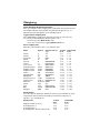
Specifications
Analytcial Models Weigh Range
SI-124
120g
SI-224
220g
SI-215D
60/210g
Toploading Models
SI-413
410g
SI-2202
2200g
SI-4102
4100g
SI-6201
6200g
Readability
0.1mg
0.1mg
0.01/0.1mg
Linearity
±0.2mg
±0.2mg
0.03/0.2mg
Pan Size
3.1” dia. (79 mm)
3.1” dia. (79 mm)
3.1” dia. (79 mm)
0.001g
0.01g
0.01g
0.1g
±0.001g
±0.01g
±0.02g
±0.1g
4.5” dia. (114mm)
7.1x7.1” (180x180mm)
7.1x7.1” (180x180mm)
7.1x7.1” (180x180mm)
Common Specifications:
Dimensions ( L x W x H ) Analytical:
Dimensions ( L x W x H ) Toploading:
Net Weight Analytical:
Net Weight Toploading:
Power Requirements:
Temperature
Humidity:
Altitude:
11.8 x 8.1 x 12.5” (290x200x300mm)
11.8 x 7.8 x 3.5” (30 x 20 x 9cm)
13.2 lbs. (6.0 kg)
10.0 lbs. (4.5 kg)
15 VDC@100 mA with AC adapter,
center pin (-)
15° - 40 °C (59° - 104° F)
80% for temperature to 31°C,
decreasing linearly to 50% relative
humidity at 40°C
3000m
Main supply voltage fluctuations not to exceed ±10% of nominal supply
voltage. Equipment is suitable for continuous operation with AC adapter.
Pollution degree: 2; Installation category: II; Sound Pressure Level emitted
by equipment does not exceed ambient noise.
!
Caution:
Use AC adapter supplied with unit only!
Consult Denver Instrument for replacement.
ii
Getting Started
Storage and Shipping Conditions
Allowable storage temperature:
+5°C…+40°C (+41°F…+104°F)
Save the box and all parts of the packaging for any future shipment of
your balance as only the complete original standard packaging ensures
safe transport. Before packing your balance, unplug all connected cables to
prevent damage. Do not expose the balance unnecessarily to extreme
temperatures, moisture, shocks, blows or vibration.
Remove the plastic wrapping, adhesive tape and styrofoam from the
balance.
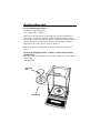
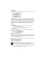
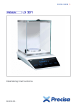
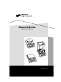
Preparing the Weighing Chamber for Balances with an Analytical Draft
Shield Chamber
Place the components listed below inside the chamber in the order given:
– Shield ring
– Weighing pan
Weighing
Pan
Shield Ring
1
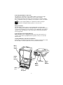
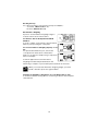
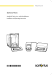
Preparing Balances with a
Round Glass Draft Shield
• Place the shield disk on the
balance. Turn the disk
counterclockwise until it
stops and is secured.
• Place the components listed
below on the balance in the
order given:
– Pan support
– Weighing pan
– Glass draft shield cylinder
– Draft shield cover
Draft Shield
Cover
Draft
Shield
Weighing
Pan
Pan
Support
Shield
Disk
Preparing Balances with a
Square Weighing Pan
• Place the components listed
below on the balance in the
order given:
- Weighing pan
Weighing
Pan
Shock
Absorber
2
Connecting the Balance to AC Power
The balance is powered by an AC adapter. Make sure that the voltage
rating printed on this unit is identical to your local line voltage.
If the voltage specified on the label or the plug design of the AC adapter
does not match the rating or standard you use, please contact your dealer.
Note:
Memo:
Use only original adapters. To operate the balance using an
external rechargeable battery pack, see “Accessories.”
Safety Precautions
The AC adapter rated to Class 2 can be plugged into any wall outlet
without requiring any additional safety precautions. The ground terminal is
connected to the balance housing, which can be additionally grounded for
operation. The data interface is also electrically connected to the balance
housing (ground).
Connecting Electronic Peripheral Devices
Make absolutely sure to unplug the balance from AC power before you
connect or disconnect a peripheral device (printer or PC) to or from the
interface port.
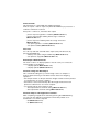
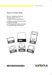
Leveling the Balance Using the Level Indicator
At the place of installation, level the balance using the leveling feet so that
the air bubble is centered within the circle of the level indicator.
Menu
Access
Switch
Bubble
Level
Indicator
RS232
Port
Menu
Access
Switch
RS232
Port
Power
Receptacle
3
Power
Receptacle
Bubble
Level
Indicator
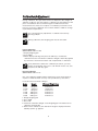
Operation
The display shows the following special codes for your information:
O displayed in the upper right corner stands for OFF. The balance was
disconnected from AC power and requires warm-up (balance reconnected
to AC power or power outage longer than 3 seconds).
O displayed in the lower left corner means standby. The display has been
turned off by the ON/OFF key. The balance is now in the ready-to-operate
mode and does not require warm-up.
means busy. Once you have turned on the balance, the
symbol will
briefly be displayed. During operation, this symbol indicates that the
balance processor is still busy processing a function and will not accept
another command to perform any other functions at this time.
Warm-up Time
To deliver exact results, the balance must warm up for at least 1 1/2 hours
(6 hours for SI-215D) after connection to AC power or after a power
outage. Only after this time will the balance have reached the required
operating temperature.
Power-On Mode
Depending on your requirements, you can change the power-on mode of
your balance.
The factory setting is: Power off -> on <-> standby (Menu code 8 5 1*)
In this default setting, when you press the ON/OFF key to turn off the
display, the balance will remain in the standby mode. This means that it
will be ready to operate without requiring any warm-up when you turn the
display back on.
On <-> standby (Menu Code 8 5 3)
In the setting “Toggle between on and standby,” the balance will
automatically turn on again after it has been temporarily disconnected
from AC power or a power failure has occurred.
Automatic power-on (Menu Code 8 5 4)
In the setting “Automatic power-on,” the balance will automatically turn
on again after it has been temporarily disconnected from AC power, the
ON/OFF key has been pressed, or after a power failure has occurred. In this
setting, you cannot use the ON/OFF key to turn off the balance. If your
balance is connected to a central power supply that is switched off
overnight, the balance will turn on automatically the next day as soon as
the power supply is switched on again.
Self-Test
After the balance has been turned on, an automatic self-test of the
balance’s electronic circuitry is performed. At the end of the self-test, a
zero readout is displayed. This means that the balance is ready to operate.
Taring
A weight can be determined accurately only from a defined zero point.
Press TARE to zero the weight display. You can tare within the entire
weighing range of the balance.
4
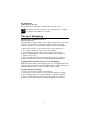
Weighing
Simple Weighing (Weight Determination)
Place your sample on the weighing pan to determine the weight. Read off
the weight indicated on the display only after the weight unit “g” or a
different unit selected appears as the stability symbol.
Toggle between weighing units
Press FUNCTION to toggle back and forth from two chosen units. the
second unit is identified by the display symbol “R1”.
- block function key (Menu Code 2 1 1*)
- mass unit conversion by toggling (Menu Code 2 1 2)
Select weighing units
Enter the codes below for first or second level units
Name
Symbol
Conversion factor
1g=
1st level
Code
2nd level R1
Code
Grams
Grams
Kilograms
Carats
Pounds
Ounces
Troy ounces
Hong Kong taels
Singapore taels
Taiwanese taels
Grains
Pennyweights
Milligrams
Parts per pound
Chinese taels
Mommes
Carats
Tola
Baht
Mesghal
g
g
kg
ct
lb
oz
ozt
tl (thl)
tl (ths)
tl (tht)
GN
dwt
mg
o (/lb)
tl (thlc)
m (mom)
k (K)
t (tol)
b (bat)
(MS)
1.0
1.0
0.001
5.0
0.0022046226
0.035273962
0.032150747
0.02671725
0.02646063
0.02666666
15.43235835
0.643014931
1000.0
1.1287667712
0.02645547175
0.2667
5.0
0.0857333381
0.06578947436
0.217
1
1
1
1
1
1
1
1
1
1
1
1
1
1
1
1
1
1
1
1
3
3
3
3
3
3
3
3
3
3
3
3
3
3
3
3
3
3
3
3
7
7
7
7
7
7
7
7
7
7
7
7
7
7
7
7
7
7
7
7
1
2*
3
4
5
6
7
8
9
10
11
12
13
14
15
16
17
18
19
20
1
1
1
1
1
1
1
1
1
1
1
1
1
1
1
1
1
1
1
1
1
2
3
4
5
6
7
8
9
10
11
12
13
14
15
16
17
18
19
20
Display Modes
You can select the display mode that best meets your individual accuracy
requirements (last numeral). The display increments possible are as
follows: 1, 2, 5, 10, 20, 50, etc.
Display mode
1st level
Code
1 8 1*
183
184
185
Highest possible accuracy
Rounding factor 2
Rounding factor 5
Rounding factor 10 (last numeral off)
5
2nd level R1
Code
3 2 1*
323
324
325
Calibration/Adjustment
During calibration, the span of the balance is adjusted to the changes in
ambient conditions. You must adjust or calibrate your new balance at the
place of installation after each warm-up period and before the first
measurement. You must also re-adjust or recalibrate your balance each
time you set it up in a different area or when ambient conditions change
(especially the temperature).
Note:
Memo:
You can interrupt any adjustment or calibration function by
pressing CAL/CF.
During calibration, the weighing pan must be unloaded.
Note:
Memo:
Internal Calibration
(Select Menu code: 1 9 3*)
1. Empty weighing pan
2. Press TARE
3. When display reads 0 grams press the CAL key to activate the
calibration function. The built-in calibration weight is internally applied
by servomotor and removed at the end of adjustment or calibration.
Note:
Memo:
If any interference affects the calibration procedure, you may
obtain a brief display of the error code "Err 02." In this case, tare
and press the CAL key again.
External Calibration
(Select Menu code: 1 9 1)
Use only calibration weights with nominal mass values and tolerances
equal to or better than the accuracy class specified for your balance.
Permissible External Calibration Weights
Model
SI-124
SI-224
SI-215D
SI-413
SI-2202
SI-4102
SI-6201
Weight
100 grams
200 grams
200 grams
200 grams
1000 grams
2000 grams
5000 grams
Minimum Weight Class
ASTM Class 1
ASTM Class 1
ASTM Class 1
ASTM Class 2
ASTM Class 2
ASTM Class 2
ASTM Class 3
1.
2.
3.
4.
Empty weighing pan
Press TARE
Press CAL
Center the calibration weight on the weighing pan. The balance then
calibrates automatically.
5. At the end of calibration, the calibration weight is displayed and the
stability symbol "g" appears.
6
Block Calibration
(Select menu code: 1 9 7)
Blocks CAL KEY so calibration or adjustments cannot be made.
Note:
Memo:
Only when menu access switch is in “locked” position (see page
13, “Menu Access Switch” for details).
Percent Weighing
Weighing in Percent (Menu Code 2 1 5)
Symbol displayed: %
This application program enables you to obtain weight readouts in percent
which are in proportion to a reference weight. The reference weight
readout is stored as a menu-defined percentage (factory setting: 100%).
1.
2.
3.
4.
Select Percent Code 2 1 5 (see back inside cover for instructions).
A “%” will be displayed on the bottom of the display.
Tare the balance and place the reference weight on the balance.
Press the FUNCTION key and the current reference percentage will
appear on the screen.
5. The screen will then flash and show the percentage on the balance.
6. Add or subtract parts and the percentage weight will be displayed.
Toggling between the Readout in Percent (%) and Weight (g)
After placing the sample on the weighing pan, you can toggle between the
readout in percent and the respective weight readout in grams by pressing
the FUNCTION key after you have stored the reference value.
Resetting the Reference Weight
1. Place the new reference weight on the balance.
2. Hold down CF for more than 2 seconds until the reading is in grams.
3. Press FUNCTION and “rEF (current setting) %” appears on display.
4. The screen will then flash and show the percentage on the balance.
5. Add or subtract parts and the percentage weight will be displayed.
7
Changing the Reference Percentage
You can change the reference percentage in cycles. Choose from the
following settings: 5, 10, 20, 50 and 100.
1. Hold down FUNCTION for more than 2 seconds until “rEF 100 %”
appears on the display
2. Briefly press FUNCTION change the setting to the desired value
3. Hold down FUNCTION for more than 2 seconds to store this value
permanently (in the non-volatile memory) after you turn off the power
Note:
Memo:
This setting is not canceled by the reset code 9 – – 1°!
When you exit the reference storage mode, “Err 22” may briefly
be displayed. This means that the new reference value has been
stored.
Storage Parameter for the Reference Weight/Value
The reference weight/value is stored:
- with full accuracy according to internal resolution
(Menu Code 3 5 1*)
- according to display accuracy (Menu Code 3 5 2)
Display Parameter for Readouts in Percent
The following display parameters can be set for readouts in percent:
The readout in percent is displayed:
- without a decimal place (Menu Code 3 6 1)
- with one decimal place (Menu Code 3 6 2*)
- with two decimal places (Menu Code 3 6 3*)
- with three decimal places (Menu Code 3 6 4)
If the weight stored is too light to be displayed, the number of decimal
places is automatically decreased.
8
Counting
Counting Mode (Menu Code 2 1 4)
Symbol displayed:
The counting program allows automatic conversion of weights into piece
counts based on a reference sample weight. A weight readout is stored as
a reference sample quantity (factory setting: 10 pcs = pieces). When you
turn on the balance, the reference sample quantity will be displayed as
“rEF 10 pcs” before you enter the piece count.
1.
2.
3.
4.
Select Count Menu Code 2 1 4 (see back inside cover for instructions).
A “ ” will be displayed on the bottom of the display.
Tare the balance and place the reference weight on the balance.
Press the function key and the current reference count will appear on
the screen.
5. The screen will then flash and show the count on the balance.
6. Add or subtract parts and the count will be displayed.
Toggling between the Piece Count (pcs) and Weight (g)
After placing the sample on the weighing pan, you can toggle between the
piece count and the respective weight readout by pressing the FUNCTION
key.
Resetting the Reference Weight
1. Place the new reference weight on the balance.
2. Hold down CF for more than 2 seconds until the reading is in grams
3. Press FUNCTION and “rEF (current setting)pcs” appears on display.
4. The screen will then flash and show the count on the balance.
5. Add or subtract parts and the count will be displayed.
Changing the Reference Sample Quantity
You can change the reference sample quantity in cycles. Choose from the
following settings: 5, 10, 20, 50 and 100.
1. Hold down FUNCTION for more than 2 seconds until change function:
“rEF…pcs” appears on the display
2. Briefly press FUNCTION until the desired setting is displayed
3. Hold down FUNCTION for more than 2 seconds to store this quantity
permanently (in the non-volatile memory) after you turn off the power.
When you exit the reference storage mode, “Err 22” may briefly
be displayed. This means that the new reference value has been
Memo:
Note:
stored.
This setting is not canceled by the reset code 9 – – 1°!
Storage Parameter for the Reference Sample Weight
The reference weight is stored:
- with full accuracy according to internal resolution
(Menu Code 3 5 1*)
- according to the display accuracy (Menu Code 3 5 2)
9
Animal Weighing/Averaging
Animal Weighing/Averaging (Menu Code 2 1 7)
Symbol displayed:
Use this program to determine the weights of live animals or weights
under unstable ambient conditions. In this program, the balance calculates
the weight as the average of a selectable number of individual weighing
operations. During averaging, the number of remaining individual
subweighing operations is shown on the application display in a “count
down” mode. Once all subweighing operations have been performed, the
calculated mean value is indicated as a stable readout on the weight
display.
Automatic Mode (Menu Code 3 8 2*)
1. Press FUNCTION to start the program for averaging the first weight.
2. The symbol “AUTO” will be displayed.
3. A count down begins for the number of readings used for averaging.
4. When the result is locked the ”
” symbol and “AUTO” flashes
5. The icon will stop flashing after you have unloaded the balance.
6. Add the next sample and the count down will begin automatically.
Note:
Memo:
You can press CF to interrupt a weight measurement in progress
at any time.
Manual Mode (Menu Code 3 8 1)
1. Press FUNCTION to start the program for averaging.
2. You can press CF to interrupt a weight measurement in progress at any
time.
3. A count down begins for the number of readings used for averaging.
4. When the result is locked, the ”
” symbol flashes on the display.
5. The icon will stop flashing after you have unloaded the balance.
6. Add the next sample and press FUNCTION to start the next count down.
Note:
Memo:
You can press CF to interrupt a weight measurement in progress
at any time.
10
Delayed Start Mode
A rule of thumb to go by for selecting the right setting to weigh animals is:
the more active an animal is, the greater the difference must be between
two successive subweights measured. Depending on individual
requirements, starting the averaging operation can be delayed either in the
automatic or manual mode until the animal you are weighing has calmed
down to a certain degree. In this case, the start criterion is defined by the
difference between two successive subweights measured. If the animal
moves, the start criterion is not met; therefore, averaging will not start.
Once the animal has calmed down, the program checks whether two
measured subweights are within the previously selected range. If so, the
actual averaging operation will be started.
Delay start until:
- difference is slight (Menu Code 3 7 1)
- difference is average (Menu Code 3 7 2*)
- difference is considerable (Menu Code 3 7 3)
During averaging, the number of subweighing operations left to perform is
shown on the weight display (countdown mode).
Changing the Number of Subweighing Operations/ “Count Down”
You can change the number of subweighing operations used to average a
weight. Change this number in cycles. You can choose from the following
settings: 5, 10, 20, 50 and 100.
1. Hold down FUNCTION for more than 2 seconds until “rEF 10” appears
on the display
2. Briefly press FUNCTION until the desired selection is displayed.
3. Hold down FUNCTION for more than 2 seconds to store this number
permanently
This setting is not canceled by the reset code 9 – – 1°!
Note:
Memo:
11
Tare Memory/Net Weighing
Tare Memory/Net Weighing (Menu Code 216)
Symbol displayed: NET
Use this program to determine the individual weight of several samples
and record the net weight.
1. Select menu code 2 1 6
2. Press the FUNCTION key to store the tare weight
3. Add the next sample, press the FUNCTION key to store the weight and
tare the balance
4. Repeat steps 2 - 3, as needed
5. When completed, press and hold CF key for at least 2 seconds
Output Parameter
- print individual components (N1) & tare weights
(Menu Code 7 3 1*)
- print net total tare weight (T1) (Menu Code 7 3 2)
Output Symbols
T1
tare weight stored in memory
N1
net weight when tare weight is stored
N
gross weight = tare + net weight
Balance Operating Parameters
In the operating menu of the balance, you can define how your balance
will adapt to ambient conditions and also how it will work to meet your
special requirements.
Adapting the Balance to Ambient Conditions
The balance can be adapted to the prevailing ambient conditions at the
place of installation:
- very stable conditions (Menu Code 1 1 1)
- stable conditions (Menu Code 1 1 2)
- unstable conditions (Menu Code 1 1 3)
- very unstable conditions (Menu Code 1 1 4)
Standard Weighing Mode – Manual Filling Mode
You can optimally adapt your balance to meet either of these
requirements.
In the manual filling mode, the display compensates for fluctuations of the
load on the balance, giving you especially fast and stable readouts.
- standard weighing mode (Menu Code 1 2 1*)
- manual filling mode (Menu Code 1 2 2)
12
Stability Range
The stability symbol will remain displayed in the case of a weight variation
+/–
0.25 digit (Menu Code 1 3 1)
0.5 digit (Menu Code 1 3 2)
1 digit (Menu Code 1 3 3)
2 digits (Menu Code 1 3 4)
4 digits (Menu Code 1 3 5)
8 digits (Menu Code 1 3 6)
Starting with the basic increments of a weight unit, the display accuracy
can be reduced by as many as three levels so that you will obtain a faster
readout with a reduced display accuracy. The display accuracy is reduced
proportionally to the selected basic increment of a weight unit. To make
this concept easier to understand, the three levels are designated as
“rounding factors” in the tables summarizing the various menu code
settings.
Tare Parameter
You can define when the balance will perform the taring operation:
- at any time (Menu Code 1 5 1)
- not until the readout is stable (Menu Code 1 5 2*)
Auto Zero Function
When this zero-tracking function is activated, any slight changes off the
zero readout are automatically tared.
- auto Zero On (Menu Code 1 6 1*)
- auto Zero Off (Menu Code 1 6 2)
Menu Access Switch Function
The menu access switch allows you to prevent change of the menu codes.
Looking at the rear of the balance, when the menu access switch is on the
right (towards the power plug), the switch is “unlocked”. This allows you
to access all of the balances’ features.
When the switch is “locked” (switched to the left or towards the RS232
port) the following codes apply:
Menu codes are accessible (8 1 1)
Menu codes are blocked (8 1 2*)
Note:
Memo:
When the menu access switch is “locked” and Code 8 1 2 is set,
the current menu code can be viewed (by following the procedure
on the inside back cover) but no changes can be saved.
Other features, such as calibration, can also be blocked by using the menu
access switch. See individual section for details.
13
Blocking the Keys
You can block all keys on the balance (except for ON/OFF ).
- accessible (Menu Code 8 3 1*)
- blocked (Menu Code 8 3 2)
Below-Balance Weighing
A port for a below-balance weighing hanger is
located on the bottom of the balance.
For Balances with an Analytical Draft Shield
Chamber:
To hook a sample on the hanger, open the belowbalance port by turning the cover plate.
For Precision Balances (Weighing Capacity of <10
kg):
To open the below-balance port, remove the
cover plate from the bottom of the balance.
Now you can attach a sample using a suspension
wire, for example.
Common applications for below-balance
weighing include density determination and
immersing a sample in a special atmosphere (medium for reaction).
Note:
Memo:
When you use the below-balance weighing hanger, you must
install a shield for protection against drafts.
Fastening an Antitheft Locking Device (for toploading balances only)
To fasten an antitheft locking device, use the lug located on the rear panel
of the balance.
14
RS-232 Interface
RS232 for Printouts or Data Transfer
You can attach a GLP printer (see accessories) or a computer into this
interface port. In addition, you can choose to have data output from your
balance to this on-line device either automatically or by pressing the
PRINT key.
The balance operating menu lets you define the various parameters for
data output.
Information on the data formats and for interfacing a computer or a
different peripheral device are available on request.
Interface Port
Depending on the balance model, unfasten or remove the protective cap
from the data interface port.
– Plug the connector into the interface port
– Secure the connector by tightening the screws
Note:
Memo:
Make absolutely sure to unplug the balance from AC power before
you connect or disconnect a peripheral device (printer or PC) to or
from the interface port.
To print or output data, press the PRINT key.
Interface Description
This description has been written for users who wish to connect their
balance, which has a built-in V24/V28-RS-232C(-S)*)/423 interface port as a
standard feature, to a computer or a different peripheral device.
By using an on-line computer, you can change, activate and monitor the
functions of the balance. If you interface with the GLP Data Printer (see
accessories), you do not need to change any settings.
Interfacing Devices with the Balance
Please note that the interface port is electrically connected to the
protective grounding conductor (protective earth = PE) of the balance
housing. The cabling supplied as accessory components is shielded and
electrically connected on both ends to the cases of the connectors. This
electrical connection may result in interference caused by ground loops or
by transient currents if you have grounded the housing or connected the
protective grounding conductor for AC power. If necessary, connect an
equipotential bonding conductor to the balance.
15
Pin Assignment Chart
Female Interface Connector:
25-position D-submini, DB25S, with screw lock hardware for cable gland
Male Connector Used: (please use connectors with the same
specifications) 25-pin D-submini, DB25S, with integrated shielded cable
clamp assembly (Amp type 826 985-1C) and fastening screws (Amp type
164 868-1)
Warning When Using Pre-wired RS-232 Connecting Cables!
RS-232 cables purchased from other manufacturers often have incorrect
pin assignments for use with Denver Instrument balances. Be sure to
check the pin assignment against the chart below before connecting the
cable, and disconnect any lines marked “Internally Connected” (e.g., pin
6). Failure to do so may damage or even completely ruin your balance
and/or peripheral device.
Pin Assignment:
Pin 1: Signal Ground
Pin 2: Data Output (TxD)
Pin 3: Data Input (RxD)
Pin 4: Internal Ground (GND)
Pin 5: Clear to Send (CTS)
Pin 6: Internally Connected
Pin 7: Internal Ground (GND)
Pin 8: Internal Ground (GND)
Pin 9: Reset _ In*)
Pin 10: Not Connected
Pin 11: +12 V
Pin 12: Reset _ Out*) Connection for a switch
Pin 13: +5 V
Pin 14: Internal Ground (GND)
Pin 15: Universal Switch
Pin 16: Not Connected
Pin 17: Not Connected
Pin 18: Not Connected
Pin 19: Not Connected
Pin 20: Data Terminal Ready (DTR)
Pin 21: Internal Ground (GND)
Pin 22: Not Connected
Pin 23: Not Connected
Pin 24: Not Connected
Pin 25: +5 V
*) = hardware restart
16
Serial Interfacing
During data communication between the balance and an on-line device
(computer), “telegram-style” information consisting of ASCII characters is
transmitted by the interface. For error-free data communication, the
interface parameters, including the baud rate, parity and handshake mode
as well as the character format, must be the same for both units. You can
change these parameters in the balance operating menu so that they match
those of the on-line device. If you do not plug a peripheral device into the
interface port on the balance, this will not generate an error code. In this
case, data will be output but not received.
Data Bits
7
not adjustable
Baud Rate
150 baud
300 baud
600 baud
1,200 baud
2,400 baud
4,800 baud
9,600 baud
19,200 baud
Code
511
512
513
5 1 4*
515
516
517
518
Parity
Mark
Space
Odd
Even
Code
521
522
5 2 3*
524
Number of Stop Bits
1 stop bit
2 stop bits
Code
5 3 1*
532
Handshake
The balance interface has a 23-byte transmit buffer and a 40-byte receive
buffer.
You can access the balance operating menu to define various handshake
parameters:
- software handshake (Menu Code 5 4 1)
- hardware handshake with 2 characters after CTS (Menu Code 5 4 2*)
- hardware handshake with 1 character after CTS (Menu Code 5 4 3)
17
Print Commands
This parameter is coupled with the stability parameter
Print on request = data is output only when the PRINT key is pressed or a
software command is received
Auto print = continuous, automatic data output
- print on request regardless of stability (Menu Code 6 1 1)
- print on request after stability, with storage of function
(Menu Code 6 1 2*)
- print on request at stability, without storage of function
(Menu Code 6 1 3)
- auto print regardless of stability (Menu Code 6 1 4)
- auto print at stability (Menu Code 6 1 5)
Auto Print
You can stop and start automatic data output (auto print function) by
pressing the PRINT key.
- start/stop auto print using the PRINT key (Menu Code 6 2 1)
- auto print not stoppable (Menu Code 6 2 2*)
Data Output at Defined Intervals
The menu code for “2 display updates” must be set if you connect the
remote display to the balance.
- 1 display update (Menu Code 6 3 1*)
- 2 display updates (Menu Code 6 3 2)
Automatic Taring after Data Output
This convenient setting lets you check weigh a series of samples or
products without having to unload the balance after each weighing
operation.
• the sample remains on the pan after the weight readout has been printed
or transferred to an on-line computer
• the balance is tared automatically after the weight readout has been
printed or transferred to an on-line computer
• you simply load the next sample or part
- data output without automatic taring (Menu Code 6 4 1*)
- data output with automatic taring (Menu Code 6 4 2)
Automatic Output of the Application Parameters
After completing an application started by pressing the FUNCTION key,
you can have the application parameters and results printed out or
transferred to an on-line computer.
- Off (Menu Code 7 1 1*)
- On (Menu Code 7 1 2)
18
Data ID Codes
To help you identify weights, piece counts, percentages, etc., a code letter
is printed or displayed in front of these values. For example, an "N"
printed or displayed in front of a weight value identifies it as a net weight.
If you set the code for "without data ID code," only net weights, results in
percent and counting results will be output. You will find the data ID codes
for a particular application program listed in the corresponding
description.
Data Output Formats
Depending on the menu code setting:
or 7 2 1 = without data ID code
or 7 2 2 = with data ID code
data will be output with either 16 (code 7 2 1) or 22 characters (code 7 2 2).
For data output of 22 characters, a 6-character ID precedes the 16 characters
reserved for the weight or other value.
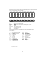
Data Output Format with 16 Characters.
Display segments that are not activated ("+" or "-" sign, leading zeros other than
zeros before the decimal point) are output as spaces.
The following data block format is output according to what is displayed
on the balance:
1
2
-
4
5
6
7
8
9
10 11 12 13 14 15 16
_ *_ _ _ *_ _ _ *_ _ _ *_ _ _ *_ _ _ *_ _ _ _ _ _ _ _
+
*
3
*
10 6 10 5 10 4 10 3 10 2 10 1 10 0
0 0 0 0 0 0 0
_________ ______ ______ ___
.
.
.
.
.
.
.
___ ___ _______________ ___
10 5 10 4 10 3 10 2 10 1 10 0
0 0 0 0 0 0
* * * * * *
* = space; U = unit
19
*
*
*
CR
*
U
U
U
LF
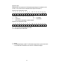
When data are output without decimals, the decimal point is suppressed (except
when a certain display mode is selected).
1
+
2
*
*
3
4
5
6
7
8
9
10 11 12 13 14 15 16
_*
_ _ _ *_ _ _*_ _ _*_ _ _*_ _ _*_ _ _ _ _
*
10 6 10 5 10 4 10 3 10 2 10 1 10 0
___ _________ _________ *
-
0
0
0
*
*
*
U
U
U
CR
LF
0
0
0
8
9
10 11 12 13 14 15 16
Data output example: +72.55 g
1
2
3
4
5
+
*
*
*
*
6
7
7
2
.
5
5
*
g
*
*
CR
LF
Characters:
1st
2nd
3rd-10th
11th
12th-14th
15th
16th
Plus or minus sign or space
Space
Weight with a decimal point, leading zeros = space
Space
Unit symbol or space
Carriage return (CR)
Line feed (LF)
If the weighing system has not stabilized, no unit symbol will be output.
Unit symbols:
*
o
g
k
c
l
o
o
t
t
t
*
*
*
g
t
b
z
z
l
l
l
*
*
*
*
*
*
*
t
h
s
t
No stability parameter
Taiwanese taels (o)
Grams
Kilograms
Carats
Pounds
Ounces
Troy ounces
Hong Kong taels
Singapore taels
Taiwanese taels
GN*
d wt
mg *
/ l b
t l c
mo m
K* *
t ol
ba t
MS *
* = space; U = unit
20
Grains
Pennyweights
Milligrams
Parts per pound
Chinese taels
Mommes
Austrian carats
Tola
Baht
Mesghal
Special Codes
Special codes are output only if the balance operating menu code 611, 614
or 615 is set (see the section entitled "Data Output Parameters").
Special status-dependent codes
1
2
3
4
5
6
*
*
*
*
*
*
7
8
A
B
9
10 11 12 13 14 15 16
*
*
*
*
*
*
CR
LF
The following status codes are output for "A B":
* * : Tare
H * : Overload
C * : Calibrate*)
L * : Underload
_ _ : All numerals indicated in stable readout
Special error-dependent codes
1
2
3
4
*
*
*
E
5
R
6
R
7
8
X
*
9
10 11 12 13 14 15 16
Y
Z
*
*
*
*
CR
LF
X = *, 0, 1 or 2 as a one-place error code
Y Z = two-place error index code
* = space
*) = The displayed status code "C" will also be output when a print command
is received and if the balance has a built-in calibration weight
21
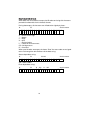
Data Output with ID Code
When data with an ID code are output, the ID code consisting of 6 characters
precedes the data with the 16-character format.
During data output, all characters are shifted to the right by 6 places.
1st
7th
22nd character
C C C C C C S * x x x x x x x x * U U U CR
* * * * * * * * . . . . . .
* * *
LF
S = Plus or minus sign
* = Space
x = Digit
U = Unit
. = Decimal point
C = Letter for an ID comment
CR = Carriage return
LF = Line feed
When special codes are output, the letters "Stat" for status code are assigned
to the 1st through the 4th characters fo the data string.
Status-dependent string:
1st
7th
13th14th
S t a t * * * * * * * * A B * * * * * * CR
22nd character
LF
A, B = status codes
Error-dependent string:
1st
7th
10 - 12th
14 - 16th
S t a t * * * * * E R R * X Y Z * * * * CR
22
22nd character
LF
ISO/GLP-compliant Printout or Record
Use of the balance as a test and measuring instrument in quality
assurance systems in compliance with the requirements of ISO, GLP, GMP
and EN (European Standards) in which proof of the balance's accurate
performance is required. The balance can record all completed calibration
or adjustment operations and print out data in compliance with the
requirements of Good Laboratory Practice (GLP). The balance, interfaced
with a data printer or a computer, can create a document that records the
date, time, serial number and model number, making it possible to clearly
trace data to the balance that generated it and the time at which it was
generated.
Select the ISO/GLP-compliant printout or record mode by setting the
respective code in the balance operating menu:
ISO/GLP-compliant printout/record mode
- Off (Menu Code 8 10 1*)
- only for adjustment/calibration and linearization functions
(Menu Code 8 10 2)
- always on (e.g., for adjustment/calibration and linearization functions,
application programs, weight readouts) (Menu Code 8 10 3)
The following menu code setting must be selected in order to obtain an
ISO/GLP- compliant printout/record:
- with data ID code (Menu Code 7 2 2)
- with application parameter (Menu Code 7 1 2)
Note:
Memo:
ISO/GLP-compliant printouts/records will not be generated if the
factory setting, menu code 7 2 1 or 711 is selected. In addition, do
not select the "Auto print" data output parameter
(Menu Code 6 1 4 or 6 1 5).
23
Data Input Formats
Commands can be input via the balance interface port to control the
balance functions.
Control commands are distinguished according to those with upper-case
letters, or special characters, and those with lower-case letters.
Control command can include up to 13 characters. each character must be
transmitted with a start bit, a 7-bit ASCII-coded character, a parity bit and
one or two stop bits.
Formats:
ESC f X CR LF
ESC K CR LF
Where:
ESC = Escape (ASCII 27)
K, f = Command characters
X = Number = Underline (ASCII 95)
CR = Carriage return (ASCII 13)
LF = Line feed (ASCII 10)
The characters CR and LF do not have to be transmitted in the data string.
Control Commands with Upper -Case Letters or Special Characters
ESC P CR LF (Print; activate/block auto print)
ESC S CR LF (Restart/self- test)
ESC T CR LF (Tare)
ESC P CR LF (Internal calibration adjustment)
The "P," "T" and "Z" commands do not affect the menu code settings of
the balance to reinitialize (turns the scale off and back on again). The "S"
command causes the processor to reinitialize (turns the scale off and back
on again).
The balance will operate according to the commands available up until the
processor is reinitialized. Once the balance has been turned on, the
processor will always recognize the codes entered by the user in the
balance operating menu.
ESC
ESC
ESC
ESC
ESC
ESC
O CR LF (Block the keys)
R CR LF (Release the keys)
K CR LF (Very stable)
L CR LF (Stable)
M CR LF (Unstable)
N CR LF (Very unstable)
Control Commands with Lower-Case Letters
All functions that can be selected by pressing the respective keys on the
balance can also be activated by commands.
ESC f 0 _ CR LF (function key)
ESC f 1 _ CR LF (cal key)
ESC s 3 _ CR LF (clear function)
ESC x 0 _ CR LF (Perform calibration test)
ESC x 1 _ CR LF (Output scale model)
ESC x 2 _ CR LF (Output serial number)
Each control command with the lower-case letters "f," "s" and "x" must
be terminated by an underline (ASCII = 95).
24
Troubleshooting
Problem
Causes
Solution
No segments
appear on the
weight display
No AC power
is available.
The AC adapter is not
plugged in.
Check the AC power
supply.
Plug in the AC adapter.
No segments
appear on the weight
display after
calibration or
adjustment
The surface on which
balance rests is not stable.
The balance has not
yet internally stabilized.
Make sure that ambient
conditions are stable.
Prevent vibrations
affecting the surface
on which the balance
rests.
Close the draft shield.
The weight display
shows "H"
The load capacity
exceeds the capacity
of the balance.
Unload the balance.
The weight display
shows "L"
or "Err 54"
The weighing pan
is not in place.
Position the pan.
The weight
readout changes
constantly
Too much vibration
or the balance
is exposed to a draft.
The draft shield is not
completely closed.
A foreign object is
caught between the pan
and the balance housing.
The below balance
weighing port is open.
The balance does not
have a stable weight
(absorbs moisture or
evaporates).
The sample is
electrostatically
charged.
Access the menu
to select the correct
code for the weighing
Close the draft shield.
The weight readout
is obviously wrong.
The balance has not
been calibrated.
The balance has not
been tared.
Calibrate the balance.
tare before weighing.
"Err 30"
RS232 is blocked.
Confirm proper pinouts
on cable.
Check selected serial
settings on balance and
attached devise.
25
Remove the foreign
object.
Close the port for
below-balance
weighing.
Care and Maintenance
Servicing
Servicing of this balance can only be done by a manufacture certified
service technician. See back cover for service information.
Cleaning
Before cleaning the balance, unplug the AC adapter from the wall outlet.
Please do not use any aggressive cleaning agents (solvents or similar
agents). Instead, use a piece of cloth which has been wet with a mild
detergent (soap). Make sure that no liquid enters the balance housing.
After cleaning, wipe down the balance with a soft, dry piece of cloth.
Carefully remove any sample residue/spilled powder by using a brush or a
hand-held vacuum cleaner.
Make sure that no liquid or dust enters the crevice surrounding the pan
adapter.
Safety Inspection
If there is any indication that safe operation of the balance with the AC
adapter is no longer warranted, turn off the power and disconnect the
equipment from AC power immediately. Lock the equipment in a secure
place to ensure that it cannot be used for the time being.
Safe operation of the balance with the AC adapter is no longer ensured
when
- there is visible damage to the AC adapter
- the AC adapter no longer functions properly
- the AC adapter has been stored for a relatively long period under
unfavorable conditions
In this case, notify Denver Instrument at 1-800-321-1135. Only service
technicians who are authorized by Denver Instrument and who have
access to the required maintenance manuals are allowed to perform
maintenance and repair work on the equipment
Note:
Memo:
The operator shall be responsible for any modifications to Denver
Instrument equipment and for any connections of cables or
equipment not supplied by this manufacturer and must check and,
if necessary, correct these modifications and connections.
If you use electrical equipment in installations and under ambient
conditions requiring higher safety standards, you must comply with the
provisions as specified in the applicable regulations for installation in your
country.
26
Accessories
GLP Printer
Cat. No. 301380.1
Printer paper (1 roll/pkg.)
Cat. No. 901044.1
Printer Ink Ribbon Cassette
Cat. No. 901045.1
RS232 Cable (9-pin for computer)
Cat. No. 102043.1
BalanceTalk XL Interface Software
Cat. No. 902227.1
Remote display
Cat. No. 301378.1
External rechargeable battery pack
Cat. No. 301379.1
Density Determination Kit
Cat. No. 301377.1
In-use cover (analytical and square pan models)
Cat. No.400208.1
In-use cover (round pan model)
Cat. No.400207.1
Warranty Instructions
1. Please return the prepaid, pre-addressed Purchase Registration Card to
Denver Instrument promptly upon your purchase of the Denver
Instrument product. The return of the card is not a condition precedent
to warranty coverage.
2. If you have any questions about a Denver Instrument Summit Series
Balance, please call toll-free, 1-800-321-1135 or FAX a description of
the problem to (303) 423-4831 for technical assistance.
3. If it becomes necessary to return your Denver Instrument product for
service, you must obtain a "Return Authorization Number" Please pack
the product securely in its original approved packing carton or an other
suitable container. Include your Return Authorization Number on the
shipping label. Shipping charges must be fully prepaid.
Return to authorized distributor or :
Denver Instrument
6542 Fig St.
Arvada, CO 80005
1-800-321-1135
27
Changing Menu Codes
To select specific functions, you will need to set the respective menu
codes.
The keys have special functions for setting menu codes:
CAL/CF = Increases a number by one with each press (the numbers
change in cycles)
TARE = Confirms and stores a code setting; and exits the menu
PRINT = Moves to the next of the three numbers of a code (1st-2nd-3rd1st, etc.)
1. Press ON/OFF to turn off the balance.
(Example: Code 8 5 4)
1
2. Press ON/OFF to turn the balance back on. While all
segments are displayed, hold down TARE until screen
has 1 on the left side of display .
8
3. Press CAL/CF to increase number on display to desired
value (until “8” appears).
8 1
4. Press PRINT to move to the 2nd number of the code.
8 5
5. Press CAL/CF to increase number on display to desired
value (until “5” appears).
1°
6. Press PRINT to move to the 3rd number (when you move
to the third number, the previously set menu code will
appear).
8
5
8
5 4
7. Press CAL/CF to increase number on display to desired
value (until “4” appears).
8
5 4°
8. Press TARE key to confirm the code you have just set
(this is indicated by the “o” after the code).
9. Press TARE key for more than 2 seconds to store the
new menu code setting.
Exiting the Menu without Storing Code Changes
Changes to the code settings are not stored if you turn off the balance by
pressing ON/OFF while selecting the code numbers or before pressing
TARE to save a setting.
Undoing All Menu Code Changes – Reset Function
The reset function lets you undo all menu code changes, which means that
you will obtain the original factory-set menu codes identified by an “*.” To
use this function, select code 9 – – 1o using the above instructions.
North and South America:
Denver Instrument Company
1855 Blake Street, Suite 201
Denver, Colorado 80202
Tel: 800.321.1135
Tel: 303.431.7255
Fax: 303.423.4831
U.K. and Ireland:
Denver Instrument Company
Denver House, Sovereign Way
Trafalgar Business Park
Downham Market
Norfolk PE38 9SW England
Tel: 44 136 63862 42
Fax: 44 136 63862 04
Europe, Asia and Australia:
Denver Instrument GmbH
Robert-Bosch-Briete 10
37079 Gottingen Germany
Tel: 49 551 20977 31
Fax: 49 551 20977 39
www.denverinstrument.com