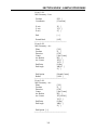
1
CENTURION 7 CNC
Operation Manual
Version 3.2
June 2003
MILLTRONICS MANUFACTURING COMPANY
1400 Mill Lane
Waconia, MN 55387
952- 442-1410
952-442-1401 Technical Support
952-442-1418 Parts
http://www.milltronics.net/
Copyright 2003 Milltronics Manufacturing
All Rights Reserved
PREFACE
This manual describes the operation of the Centurion 5, 6 and 7 CNC controls. From the
operator’s standpoint there is no visible difference. Functionality is the same in all controls. The
Centurion 7 hardware offers enhanced performance, larger memory, and faster processing. When
this manual makes reference to Centurion 7, it implies Centurion 5 and 6 also. The Centurion 7
has five controllable axes in its basic configuration: X, Y, Z, A, and B. This manual assumes that
the tool moves with respect to the workpiece.
The programming portion of this manual is divided into two sections: text programming and
conversational programming. The conversational programming section is designed primarily to
explain the various menus, screen entries, and the general flow from one screen to another.
Detailed explanations of each function are described in the M and G code sections and should be
referenced there.
iii
TABLE OF CONTENTS
PREFACE ...................................................................................................................................... iii
AXIS DEFINITIONS ..................................................................................................................... 1
INTRODUCTION .......................................................................................................................... 3
SECTION ONE - PROGRAM CONFIGURATION ..................................................................... 7
Block ........................................................................................................................................... 7
Program....................................................................................................................................... 8
Main program, subprogram, and subroutines ............................................................................. 8
Command format ranges............................................................................................................. 9
Command formats for axes: M and G codes ............................................................................ 10
SECTION TWO - FRONT PANEL OPERATION...................................................................... 11
Centurion 7 Front Panel ............................................................................................................ 12
F1 (Home) Main-Home ............................................................................................................ 15
F10 (Here) Home-Here ............................................................................................................. 15
F2 (JOG) Main-Jog ................................................................................................................... 16
F3 (HDW) Main-HDW............................................................................................................. 17
F4 (Run) Main-Run................................................................................................................... 20
F9 (Halt/Resum) Main-Run-Halt/Resume................................................................................ 21
F2 (Old) Main-Run-Old............................................................................................................ 22
F3 (Block) Main-Run-Block..................................................................................................... 22
F4 (OStop) Main-Run-OStop ................................................................................................... 22
F5 (BSkip) Main-Run-BSkip.................................................................................................... 22
F6 (Displ) Main-Run-Displ....................................................................................................... 23
F1 (Dist) Main-Run-Displ-Dist ................................................................................................ 23
F2 (Error) Main-Run-Displ-Error ............................................................................................. 24
F3 (Graph) Main-Run-Displ-Graph.......................................................................................... 24
F1 (Rot) Main-Run-Displ-Graph-Rot ....................................................................................... 25
F2 (Pan) Main-Run-Displ-Graph-Pan....................................................................................... 26
F3 (Wind) Main-Run-Displ-Graph-Wind................................................................................. 27
F4 (Auto) Main-Run-Displ-Graph-Auto................................................................................... 27
F5 (Zoom-) Main-Run-Displ-Graph-Zoom-............................................................................. 27
F6 (Zoom+) Main-Run-Displ-Graph-Zoom+ ........................................................................... 28
F7 (Limit) Main-Run-Displ-Graph-Limit................................................................................. 28
F8 (Zone) Main-Run-Displ-Graph-Zone .................................................................................. 28
F9 (Coord) Main-Run-Displ-Graph-Coord............................................................................... 28
F10 (Fresh) Main-Run-Displ-Graph-Fresh............................................................................... 28
Help (Clear) Main-Run-Displ-Graph-Clear.............................................................................. 28
F4 (Diag) Main-Run-Displ-Diag .............................................................................................. 28
F7 (OBS) Main-Run-Displ-Obs................................................................................................ 29
F9 (Shell) Main-Run-Displ-Shell ............................................................................................. 29
F7 (Menu) Main-Run-Menu ..................................................................................................... 30
F8 (Dry) Main-Run-Dry ........................................................................................................... 30
F10 (HDW) Main-Run-HDW................................................................................................... 31
Help (TlSet) Main-Run-TlSet ................................................................................................... 31
F5 (MDI) Main-MDI ................................................................................................................ 32
F1 (Gcode) Main-MDI-Gcode.................................................................................................. 32
F2 (Mcode) Main-MDI-Mcode................................................................................................. 33
v
TABLE OF CONTENTS
F6 (Displ) Main-Displ............................................................................................................... 34
F7 (Parms) Main-Parms............................................................................................................ 34
F1 (Setup) Main-Parms-Setup .................................................................................................. 35
F2 (Prec) Main-Parms-Setup-Prec............................................................................................ 36
F3 (Power) Main-Parms-Setup-Power...................................................................................... 36
Tool Changer Information ........................................................................................................ 40
F4 (Axis) Main-Parms-Setup-Axis ........................................................................................... 42
F5 (Misc) Main-Parms-Setup-Misc .......................................................................................... 48
Basic Machine Info ................................................................................................................... 48
Software Options ...................................................................................................................... 53
CAD Parameters ....................................................................................................................... 54
Post M codes Table................................................................................................................... 55
European Code Parameter and Operation Descriptions............................................................ 55
F4 (FdOvr) Main-Parms-Setup-OVRs-FdOvr.......................................................................... 57
F5 (HwOvr) Main-Parms-Setup-OVRs- HwOvr...................................................................... 58
F6 (SpOvr) Main-Parms-Setup-OVRs-SpOvr.......................................................................... 59
F7 (BSC) Main-Parms-Setup-BSC ........................................................................................... 60
F9 (DOS) Main-Parms-Setup-DOS .......................................................................................... 60
F2 (Coord) Main-Parms-Coord................................................................................................. 61
F3 (TOOL) Main-Parms-Tool .................................................................................................. 62
F4 (D Off) Main-Parms-D Off.................................................................................................. 63
F5 (H Off) Main-Parms-H Off.................................................................................................. 64
F6 (Save) Main-Parms-Save ..................................................................................................... 64
F7 (Load) Main-Parms-Load .................................................................................................... 64
F8 (Prog) Main-Parms-Prog ..................................................................................................... 65
F9 (CTRL) Main-Parms-CTRL ................................................................................................ 68
Serial Port Data ......................................................................................................................... 71
Digitizing Parameters................................................................................................................ 72
F10 (User) Main-Parms-User ................................................................................................... 74
F8 (Prog) Main-Prog................................................................................................................. 75
F1 (Text) Main-Prog-Text ........................................................................................................ 76
F1 (Edit) Main-Prog-Text-Edit ................................................................................................. 76
Text Editing Terms ................................................................................................................... 76
Entering and Editing Text......................................................................................................... 76
Key Definitions......................................................................................................................... 77
F1 (Block) Main-Prog-Text-Edit-Block ................................................................................... 77
F2 (Cursr) Main-Prog-Text-Edit-Cursr..................................................................................... 78
F3 (Words) Main-Prog-Text-Edit-Words ................................................................................. 79
F4 (Misc) Main-Prog-Text-Edit-Misc ...................................................................................... 79
F5 (Ins) Main-Prog-Text-Edit-Ins............................................................................................. 81
F6 (Del) Main-Prog-Text-Edit-Del........................................................................................... 81
HELP (Verf) Main-Prog-Text-Edit-Verf.................................................................................. 81
F2 (New) Main-Prog-Text-New ............................................................................................... 82
F3 (Old) Main-Prog-Text-Old .................................................................................................. 82
F4 (Any) Main-Prog-Text-Any................................................................................................. 82
F7 (Menu) Main-Prog-Text-Menu............................................................................................ 83
vi
TABLE OF CONTENTS
F2 (Conv) Main-Prog-Conv...................................................................................................... 84
F1 (Edit) Main-Prog-Conv-Edit................................................................................................ 84
Definitions of the Edit Keys ..................................................................................................... 85
Definitions of the Store/Input Keys .......................................................................................... 88
F2 (New) Main-Prog-Conv-New.............................................................................................. 89
F3 (Old) Main-Prog-Conv-Old ................................................................................................. 89
F4 (Any) Main-Prog-Conv-Any ............................................................................................... 89
Main-Prog-Conv ....................................................................................................................... 89
F7 (Menu) Main-Prog-Conv-Menu .......................................................................................... 91
F9 (Verf) Main-Verf ................................................................................................................. 91
F3 (Block) Main-Verf-Block .................................................................................................... 93
F4 (OStop) Main-Verf-OStop................................................................................................... 93
F5 (BSkip) Main-Verf-BSkip ................................................................................................... 93
F6 (Displ) Main-Verf-Displ...................................................................................................... 94
F1 (Next) Main-Verf-Displ-Dist............................................................................................... 94
F2 (Error) Main-Verf-Displ-Error ............................................................................................ 94
F3 (Graph) Main-Verf-Displ-Graph ......................................................................................... 95
F4 (Diag) Main-Verf-Disp-Diag............................................................................................... 95
F8 (Dry) Main-Verf-Dry........................................................................................................... 96
F9 (Halt) Main-Verf-Halt F9 (Resum) Main-Verf-Resum....................................................... 96
F10 (Util) Main-Util ................................................................................................................. 96
F1 (Probe) Main-Util-Probe...................................................................................................... 97
F2 (XyDig) Main-Util-XyDig................................................................................................... 98
F3 (Files) Main-Util-Files......................................................................................................... 98
F1 (Load) Main-Util-Files-Load............................................................................................... 99
F2 (Save) Main-Util-Files-Save.............................................................................................. 100
F3 (Rename) Main-Util-Files-Rename ................................................................................... 100
F4 (Copy) Main-Util-Files-Copy............................................................................................ 100
F5 (8Ram) Main-Util-Files-4Ram ...................................................................................... 100
F9 (Erase) Main-Util-Files-Erase ........................................................................................... 100
F4 (RS232) Main-Util-RS232................................................................................................. 100
F1 (COM1 or COM 2) ............................................................................................................ 100
F5 (Send) Main-Util-RS232-Send .......................................................................................... 101
F6 (Recev) Main-Util-RS232-Recev ...................................................................................... 101
F7 (8Ram) Main-Util-RS232-8Ram ................................................................................... 102
F5 (Tlchg) Main-Util-Tlchg.................................................................................................... 102
F6 (DNC) Main-Util-DNC ..................................................................................................... 103
F3 (Fast) Main-Util-DNC-Fast ............................................................................................... 104
F1 (RS232).............................................................................................................................. 104
F2 (File) .................................................................................................................................. 104
F3 (Disk) ................................................................................................................................. 104
F4 (Any).................................................................................................................................. 104
F5 (Old)................................................................................................................................... 104
F6 (Ram4) ............................................................................................................................. 104
F1 (First) ................................................................................................................................. 105
F2 (Block) ............................................................................................................................... 105
vii
TABLE OF CONTENTS
F3 (Tool) ................................................................................................................................. 105
F4 (Cont)................................................................................................................................. 105
F9 (Skip) ................................................................................................................................. 105
F10 (Mirr) ............................................................................................................................... 105
F3 (Fast) .................................................................................................................................. 105
F4 (Run) Main-Util-DNC-Run ............................................................................................... 106
F9 (Verf) Main-Util-DNC-Verf.............................................................................................. 106
F8 (Info) Main-Util-Info ......................................................................................................... 107
F1 (Std) Main-Util-Info-Std.................................................................................................... 107
F2 (Sys) Main-Util-Info-Sys................................................................................................... 108
F3 (Fp) Main-Util-Info-Fp...................................................................................................... 109
F4 (Path) Main-Util-Info-Path ................................................................................................ 110
F5 (Time) Main-Util-Info-Time ............................................................................................. 111
F6 (Ram) Main-Util-Info-Ram ............................................................................................... 111
F7 (Diag) Main-Util-Info-Diag............................................................................................... 112
F9 (Blank) Main-Util-Blank ................................................................................................... 112
F10 (Command) Main-Util-Command ................................................................................... 112
Help (AugRv) Main-Util-AugRV........................................................................................... 112
SECTION THREE - CONVERSATIONAL INPUT SCREENS............................................... 113
Program setup ......................................................................................................................... 114
F1 (Pos) Main-Prog-Conv-Pos ............................................................................................... 115
F2 (Mill) Main-Prog-Conv-Mill ............................................................................................. 115
F1 (Start) Mill-Start ................................................................................................................ 116
F2 (Geom) Mill-Geom............................................................................................................ 117
F1 (Line) Mill-Geom-Line...................................................................................................... 117
F2 (Arc) Mill-Geom-Arc ........................................................................................................ 120
F3 (Tangs) Mill-Geom-Tangs................................................................................................. 123
F4 (CGen) Mill-Geom-CGen.................................................................................................. 125
F7 (Islnd) Mill-Geom-Islnd .................................................................................................... 125
F8 (E-Isl) Mill-Geom-E-Isl..................................................................................................... 126
F3 (Misc) Mill-Misc ............................................................................................................... 132
F4 (End) Mill-End................................................................................................................... 132
F5 (Pockt) Mill-Pockt ............................................................................................................. 142
F1 (Setup) Mill-Pockt-Setup................................................................................................... 142
F2 (Circ) Mill-Pockt-Circ ....................................................................................................... 143
F1 (Clear) Mill-Pockt-Circ-Clear ........................................................................................... 143
F2 (Fin) Mill-Pockt-Circ-Fin .................................................................................................. 144
F3 (Rect) Mill-Pockt-Rect ...................................................................................................... 144
F1 (Clear) Mill-Pockt-Rect-Clear ........................................................................................... 144
F2 (Fin) Mill-Pockt-Rect-Fin.................................................................................................. 145
F3 (Face) Mill-Pockt-Rect-Face ............................................................................................. 145
F4 (Manul) Mill-Pockt-Manul ................................................................................................ 145
F5 (Polyg) Mill-Pockt-Polyg .................................................................................................. 147
F6 (Frame) Mill-Frame ........................................................................................................... 147
F1 (Setup) Mill-Frame-Setup.................................................................................................. 147
F2 (Circ) Mill-Frame-Circ ...................................................................................................... 148
viii
TABLE OF CONTENTS
F3 (Rect) Mill-Frame-Rect ..................................................................................................... 148
F5(Poly) Mill-Frame-Poly ...................................................................................................... 148
F7 (3dPkt) Mill-3dPkt............................................................................................................. 149
F1 (Start) Mill-3dPkt-Start...................................................................................................... 149
F4 (End) Mill-3dPkt-End........................................................................................................ 150
F5 (3dArc) Mill-3dPkt-3dArc................................................................................................. 153
F9 (Thred) Mill-Thred ............................................................................................................ 157
F3 (Drill) Drill......................................................................................................................... 157
Drill ..................................................................................................................................... 158
Drill/Dwell .......................................................................................................................... 158
Drill/Peck ............................................................................................................................ 159
Chip Breaker Drill............................................................................................................... 159
Bore..................................................................................................................................... 159
Bore/Dwell.......................................................................................................................... 160
Bore 2.................................................................................................................................. 160
Fast bore.............................................................................................................................. 160
Fine bore ............................................................................................................................. 160
Back bore ............................................................................................................................ 161
Manual bore ........................................................................................................................ 161
Counter bore........................................................................................................................ 161
Tap (Drill-Start-Tap)........................................................................................................... 162
Soft right tap ....................................................................................................................... 162
Soft left tap.......................................................................................................................... 162
Hard right tap ...................................................................................................................... 162
Hard left tap ........................................................................................................................ 163
Hard peck right tap.............................................................................................................. 163
Hard peck leftt tap............................................................................................................... 163
F2 (Pos) Drill-Pos, F3 (Misc) Drill-Misc, F4 (Call) Drill-Call .............................................. 163
F5 (End) .................................................................................................................................. 166
F4 (Bolt).................................................................................................................................. 172
F5 (TChng) Tool Change........................................................................................................ 176
F6 (Misc)................................................................................................................................. 177
F7 (Call) .................................................................................................................................. 178
F8 (Spec)................................................................................................................................. 179
F1 (Parms) Spec-Parms........................................................................................................... 180
F2 (Tools) Spec-Tools ............................................................................................................ 180
F4 (Scale) Spec-Scale ............................................................................................................. 181
F5 (Rot) Spec-Rot ................................................................................................................... 182
F6 (Mirr) Spec-Mirr................................................................................................................ 183
F7 (Flz) Spec-Flz .................................................................................................................... 183
F8 (Text) Spec-Text................................................................................................................ 184
F9 (Subs)................................................................................................................................. 184
F1 (Gosub) Subs-Gosub.......................................................................................................... 185
F2 (Start) Subs-Start ............................................................................................................... 186
F3 (End) Subs-End.................................................................................................................. 186
Sample Program Using Subroutines ....................................................................................... 187
ix
TABLE OF CONTENTS
End of Program ....................................................................................................................... 190
SECTION FOUR - PREPARATORY FUNCTIONS (G CODES)............................................ 191
G Codes................................................................................................................................... 191
Interpolation functions ............................................................................................................ 194
Positioning (G00) rapid traverse (modal) ............................................................................... 194
Positioning (G01) Feed travels (modal).................................................................................. 195
Polar definition of a line ......................................................................................................... 196
Circular interpolation (G02, G03)........................................................................................... 197
Corner rounding (,R)............................................................................................................... 210
Angle chamfering (,C) ............................................................................................................ 211
Back line ................................................................................................................................. 212
Helical cutting (G02, G03) ..................................................................................................... 214
Dwell command (G04) ........................................................................................................... 215
Exact stop (G09) ..................................................................................................................... 215
Set data on/off (G10, G11)...................................................................................................... 216
Clear floating zero (G12) ........................................................................................................ 216
XY plane (modal) (G17)......................................................................................................... 216
XZ plane (modal) (G18) ......................................................................................................... 216
YZ plane (modal) (G19) ......................................................................................................... 216
Inch dimensioning mode (modal) (G20)................................................................................. 216
Metric dimensioning mode (modal) (G21) ............................................................................. 217
Safe zone on/off (G22, G23)................................................................................................... 217
Autoroutines............................................................................................................................ 217
Circular pocket clear (G24) .................................................................................................... 218
Circular finish inside (G25) .................................................................................................... 219
Circular finish outside (G26) .................................................................................................. 221
Reference point return (G28, G29, G30) ................................................................................ 222
Z to clearance (G31) ............................................................................................................... 225
Z to tool change (G32)............................................................................................................ 225
Facing cycle (G33).................................................................................................................. 225
Rectangular pocket clear (G34) .............................................................................................. 225
Rectangular finish inside (G35) .............................................................................................. 226
Rectangular finish outside (G36) ............................................................................................ 229
Threading (G39)...................................................................................................................... 230
Polygon Cycle (G666) ............................................................................................................ 231
Cutter compensation (G40, G41, G42) ................................................................................... 234
Inside "V" Cutter Compensation ............................................................................................ 238
Sample part exercise ............................................................................................................... 238
How To Compensate for a Cavity .......................................................................................... 243
No-movement (G65)............................................................................................................... 244
Auto cutter compensation (G45, G46, G47)........................................................................... 250
Sample Programs .................................................................................................................... 251
Tool length offset (G43, G44, G49)........................................................................................ 253
Cancel scaling (G50) Set scaling (G51).................................................................................. 254
Coordinate systems ................................................................................................................. 256
Machine coordinate system (G53) .......................................................................................... 256
x
TABLE OF CONTENTS
Work coordinate systems (G54 - G59)(G5#0…G5#9)........................................................... 257
Local coordinate system (G52)............................................................................................... 257
Single direction or one shot rapid positioning (G60).............................................................. 259
Exact stop mode (modal) (G61).............................................................................................. 259
Tapping mode (modal) (G63) ................................................................................................. 259
Cutting mode (modal) (G64) .................................................................................................. 259
Calling a program (G65 P)...................................................................................................... 259
Coordinate system rotation (G68) Cancel Rotation (G69) ..................................................... 260
3D Rotation (G0, G1, G2, G3, G68 AND G69) ..................................................................... 262
Part Scaled then Rotated ......................................................................................................... 263
Part Rotated then Scaled ......................................................................................................... 264
Cancel mirror image (G70)..................................................................................................... 265
Set mirror image (G71)........................................................................................................... 265
Canned cycles ......................................................................................................................... 266
Bolt hole routine (G72)........................................................................................................... 272
High speed peck drilling cycle (G73) ..................................................................................... 275
Left hand soft tapping cycle (G74) ......................................................................................... 276
Counter Bore (G75) ................................................................................................................ 277
Fine bore cycle (G76) ............................................................................................................. 278
Custom drill cycle (G77) ........................................................................................................ 279
Drilling cycle, manual bore (G78) .......................................................................................... 280
Canned cycle cancel (G80) ..................................................................................................... 280
Drilling cycle (G81)................................................................................................................ 281
Drill/Dwell cycle (G82) .......................................................................................................... 281
Peck drilling cycle (G83) ........................................................................................................ 282
Right-hand soft tapping cycle (G84)....................................................................................... 283
Boring cycle (G85) ................................................................................................................. 284
Fast bore cycle (G86).............................................................................................................. 285
Back Boring cycle (G87) ........................................................................................................ 286
Hard tap cycle (G88)............................................................................................................... 288
Bore/Dwell cycle (G89).......................................................................................................... 289
Absolute/Incremental Mode.................................................................................................... 292
Absolute mode (modal) (G90) ................................................................................................ 292
Incremental mode (modal) (G91) ........................................................................................... 293
Floating zero (G92)................................................................................................................. 294
Inverse Time Feed Mode (G93).............................................................................................. 295
Feed Per Minute (G94) ........................................................................................................... 296
Feed Per Revolution (G95) ..................................................................................................... 297
Return to initial level or to R level (G98/G99) ....................................................................... 297
G271 (Pocket Clear) ............................................................................................................... 297
Store Restore parameters (G990/G991).................................................................................. 300
Read byte parameter (G995)................................................................................................... 301
Write byte parameter (G996) .................................................................................................. 301
Force Error (G997) ................................................................................................................. 302
Beep (G998)............................................................................................................................ 302
Custom G codes ...................................................................................................................... 302
xi
TABLE OF CONTENTS
SECTION FIVE - MISCELLANEOUS FUNCTIONS (M CODES) ........................................ 303
Program stop (M00)................................................................................................................ 305
Optional stop (M01)................................................................................................................ 305
Block skip ( / )......................................................................................................................... 305
End of program (M02, M30, M99)......................................................................................... 305
Spindle on/off (M03, M04, M05) ........................................................................................... 305
Tool change (M06) ................................................................................................................. 305
Coolants on/off (M07, M08, M09) ......................................................................................... 306
Clamp for rotary table (M10).................................................................................................. 306
Release clamp on rotary table (M11)...................................................................................... 306
Tool changer codes (M19-M28) ............................................................................................. 306
Disable Drives (M31) ............................................................................................................. 306
Channel (M32) ........................................................................................................................ 307
Miscellaneous M codes (M65/75, M67/77, M68/78, M69/79, M50/60)................................ 307
Graphics off/on (M90, M91)................................................................................................... 307
3D Sweep off/on (M93, M94) ................................................................................................ 307
Tapered Walls (M95).............................................................................................................. 308
Rounded Walls (M96)............................................................................................................. 312
Pocket Clear (M97)................................................................................................................. 316
Subprogram call (M98)........................................................................................................... 317
Subprogram terminate (M99) ................................................................................................. 317
Preparation of subprogram...................................................................................................... 318
Subprogram execution ............................................................................................................ 319
Custom M codes ..................................................................................................................... 320
SECTION SIX - PARAMETRIC PROGRAMMING................................................................ 323
Parametric reference ............................................................................................................... 323
Parametric assignment command ........................................................................................... 323
PB byte parameter................................................................................................................... 323
Arithmetic operators ............................................................................................................... 324
Relational operators ................................................................................................................ 324
Function operators .................................................................................................................. 325
Mathematic expressions.......................................................................................................... 326
Conditional statements............................................................................................................ 326
IF-THEN ................................................................................................................................. 326
WHILE-WEND ...................................................................................................................... 327
Transfer statements ................................................................................................................. 327
GOTO statement ..................................................................................................................... 328
CALL statement...................................................................................................................... 328
GOSUB and RETURN ........................................................................................................... 328
Computational functions......................................................................................................... 330
Text command ........................................................................................................................ 333
Miscellaneous Commands ...................................................................................................... 335
IPIN......................................................................................................................................... 340
OPIN ....................................................................................................................................... 340
Parts Inspection and Digitizing Commands............................................................................ 340
Back line ................................................................................................................................. 341
xii
TABLE OF CONTENTS
MOD ....................................................................................................................................... 342
ORIGIN................................................................................................................................... 342
SECTION SEVEN - SAMPLE PROGRAMS............................................................................ 347
APPENDIX................................................................................................................................. 405
Error Messages........................................................................................................................ 405
Byte Parameters ...................................................................................................................... 419
Real Parameters ...................................................................................................................... 422
xiii
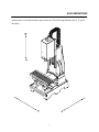
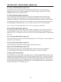
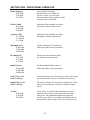
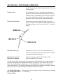
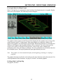
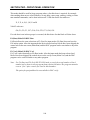
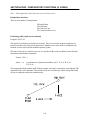
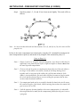
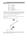
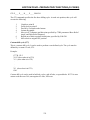
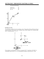
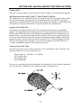
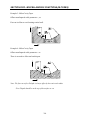
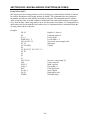
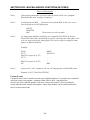
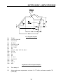
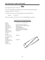
AXIS DEFINITIONS
All directions are referenced with respect to the tool. The following illustrates the X, Y, and Z
directions.
1
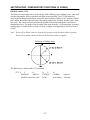
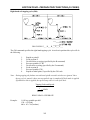
INTRODUCTION
A group of commands given to the CNC for operating the machine is called a program. By
specifying commands the tool is moved along a straight line or an arc, and machine functions
such as coolant on/off, tool change, or spindle on/off are performed.
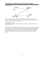
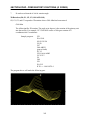
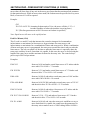
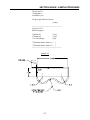
The function of moving the tool along straight lines and arcs is called interpolation.
Linear Interpolation
Circular Interpolation
When the commanded position to be reached by the tool is executed, the CNC moves the tool to
that position via the circular or linear interpolation modes. The position is given as a coordinate
value in a rectangular Cartesian coordinate system.
Coordinates
3
INTRODUCTION
The following types of coordinate systems are available.
1. Machine system
2. Work coordinate system
3. Local coordinate system
4
INTRODUCTION
The position to be reached by the tool is commanded with a coordinate value referenced to one
of the above coordinate systems. The coordinate value consists of one component for each axis,
X, Y, and Z. Coordinate values may be given in either absolute or incremental mode. In
absolute mode, the tool moves to a point the programmed distance from the zero point of the
coordinate system. In incremental mode, the tool moves to a point the programmed distance
from the current tool position.
5
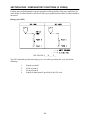
SECTION ONE - PROGRAM CONFIGURATION
By definition, a program is a group of commands given to the CNC for operating a machine. By
specifying commands, the tool is moved along a straight line or an arc, or the spindle motor is
turned on and off. In a program, specify the commands in the sequence of actual tool
movements.
Block
Block
Block
Program
Block
Tool movement sequence
.
.
.
Block
A group of commands at each step of the sequence is called the block. The program consists of a
group of blocks for a series of machine moves. An optional number for definition of each move
is called the block number, and the number for naming each program is called the program
number.
The block and the program have the following configurations.
Block
Each block begins with an optional number and ends with a <CR> carriage return.
7
SECTION ONE – PROGRAM CONFIGURATION
Program
Normally a program number is specified at the beginning of a program, and a program end code
(M99, M02, M30) is specified at the end of the program. Neither is required; however, it may be
advantageous to omit the program end code from programs that are used as subprograms. An end
program code is assumed when the end of the main program is encountered.
Main program, subprogram, and subroutines
When it is necessary to machine the same pattern at many places on a part, a program for the
pattern should be created. This is called a subprogram. When a “M98" or “Call” (subprogram
call) appears in the main program, the commands of the subprogram are performed before
execution of the next block of the main program.
8
SECTION ONE – PROGRAM CONFIGURATION
Subprograms can be used to build part libraries of commonly used patterns and can reside
anywhere in memory.
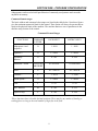
Command format ranges
The basic address and command value ranges are listed in the table below. Note these figures
give the maximum numerical limit for the control. These limits will always be greater than or
equal to the physical limits of the machine. The machine limits are set via parameters in the
machine setup section of the control.
Command Format Ranges
FUNCTIONS
COMMAND
LETTER
INCH INPUT
METRIC INPUT
Subprogram # and
Program #
O
1 - 9999
1 - 9999
Sequence #
N
1 - 99999
1 - 99999
Preparatory
function
G
0 - 999
0 - 999
XYZUVWQ
ABCIJKRP
0 ± 999.9999
0 ± 9999.9999
Dwell
P
.01 - 9999.99
.01 - 9999.99
Feedrates *
F
.1 - 999.9
.1 - 9999
Spindle speed *
S
1 - 99999
1 - 99999
Tools
T
0 - 99
0 - 99
Misc. function
M
0 - 999
0 - 255
Repeat or loop
L
0 - 999
0 - 999
Dimension * words
*These functions have selectable decimal positions. There may be any number of leading or
trailing places as long as the total number of digits fits in the field.
9
SECTION ONE – PROGRAM CONFIGURATION
Command formats for axes: M and G codes
Axis commands can be programmed in a calculator format. No leading or trailing zeros are
necessary. Whole numbers may be programmed without the decimal point. A decimal point may
be used with mm, inches, or second values. The location of the decimal point is as follows.
Z15.0
F10.0
G04 P1
Z15 millimeters or Z15 inches
10 mm/min., or 10 inch/min.
Dwell for one second
(same as Z15)
(same as F10)
(same as G4 P1)
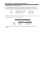
The following addresses can be used with a decimal point: X, Y, Z, U, V, W, A, B, C, I, J, K, R,
F, P, Q, AA, AB, XC, YC, E, H, L, N, O, S, and T.
Axis Min/Max Values for Standard Systems
Metric
English
Degrees
Least Increment
0.001 mm
0.0001 inch
0.001 deg
Maximum Value
99999.999 mm
99999.9999 inch
99999.999 deg
Axis positions are stored in floating point; therefore, digit commands greater than 8 will be
accepted.
10
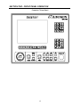
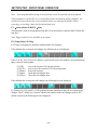
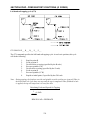
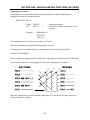
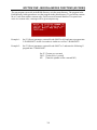
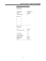
SECTION TWO - FRONT PANEL OPERATION
The Centurion 6 front panel has two 16-key keypads and 12 function keys. The keypads are used
to enter the alphanumeric data requested by the CNC. The upper keypad is used primarily to
enter alpha characters. To enter one of the shifted characters simply press and release the Shift
key then the character. After the character has been entered, the control automatically returns to
the non-shifted character set. Shift also works in the same manner on the lower or numeric
keypad. Spaces between commands are optional when data is entered, but the Enter must be
pushed to end a line of data or to go to the next function. The operation of the 12 function keys
changes as different menus are displayed on the display. The following sections detail each
function key.
The lower section of the panel is dedicated to manual machine cycles. Located on the far left of
the panel is the electronic handwheel, which when turned in the handwheel mode will cause the
selected axis to move. Next to the handwheel are the manual feed controls for the machine's
axes. Turning the feedrate override will modify the current machine feedrate by the indicated
percentage. Pressing the Feedhold button will cause axis motion to stop. To restart axis motion,
press Feedhold again and press the Cycle Start button. The Cycle Start Button needs to be
pressed anytime a machine command is to be executed. Cycle Start will blink when it needs to
be depressed.
The next section of the panel deals with the spindle and coolant controls. The spindle override
switch will modify the current spindle rpm by the selected percentage. If the machine is not
equipped with a variable speed spindle option, the override switch has no effect on the spindle.
The spindle CCW, CW and Stop buttons will override the current control commands giving the
operator full manual override capabilities. The active state of the spindle will be represented by
the illuminated button. The coolant buttons (Mist and Flood) work identically to CW and CCW.
When they are lit, the function is active; however, the coolant will not turn on until the spindle is
started. The Tool Reset button is only active during an M6 command. This button is a safety
interlock, which prevents the spindle from starting during a manual tool change. The button will
start flashing during a tool change and will need to be depressed after the tool change is
completed before program operation can be resumed. The Emergency Stop button, when
pushed, will stop all machine actions instantly. Once Emergency Stop is depressed, the Reset
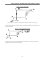
button will flash indicating that it must be pushed before any machine motion can be performed.
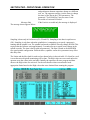
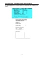
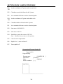
The control is always in an Emergency Stop state after power-on. The following diagram shows
the layout of a Centurion 6 front panel.
11
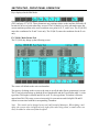
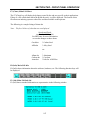
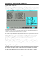
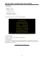
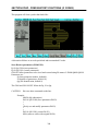
SECTION TWO - FRONT PANEL OPERATION
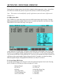
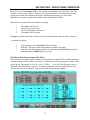
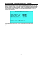
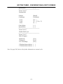
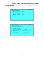
Centurion 7 Front Panel
12
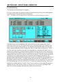
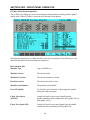
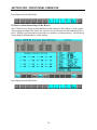
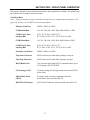
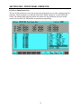
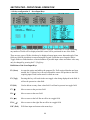
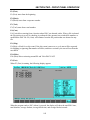
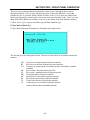
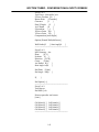
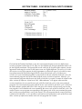
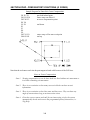
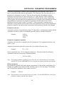
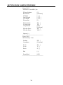
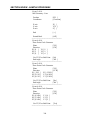
SECTION TWO - FRONT PANEL OPERATION
Diagram of Main Screen
1
2
3
4
5
6
7
8
RunTime
When you are verifying a program the runtime displays the calculated time to make the
parts. When you are running a program it shows the elapsed time since the program was
started. The total of all program run times are kept in the “Job Time” parameter (F7 Parms
– F9 Ctrl).
History Line
History Line shows you where you are in the software and where you came from. If you
are modifying the tool table, the history line would say Main-Parms-Tool-Edit.
Active Program
Active Program displays the program that you are running or verifying. If you are editing a
program it will show the active edit program. If you are sending a file over the RS-232 it
will show the program being sent.
Current Position
Current Position is the position relative to the work offset zero.
Next Position
If you are running or verifying, the Next Position is the position that the machine is going
to.
Distance
Distance is the remaining distance the machine has left to go to finish the move being
executed.
The Function Keys
Highlighted Function Keys are active or available.
Status Window
Status Window displays detailed information on the state of the control. A detailed
description is given below.
13
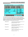
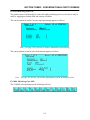
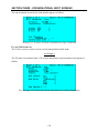
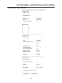
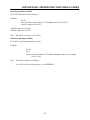
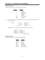
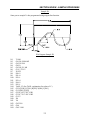
SECTION TWO - FRONT PANEL OPERATION
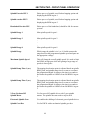
Diagram of Status Window
1
2
3
4
5
6
7
8
9
10
11
12
13
14
The \ changes back and forth to / and \ each time the status window is updated.
Comp: Tool Radius Compensation (Left, Right or Cancelled)
Tool: The first two digits indicate the active tool number. The second two digits in
parentheses indicate the pending tool number. If you execute a T14 without the M6 the
pending tool number will be 14.
The tool length.
The tool radius.
Plane and work offset: The plane is XY (G17), ZX (G18), or YZ (G19). The work offset
shows the current work offset G54 (0)…G59 (9).
Clearance or R-Plane.
Interpolation, Linear (Feed), Linear (Rapid), Circular (CW), or Circular (CCW)
Feedrate: The programmed feedrate and its units (English feed per minute) ipm, (Metric
feed per minute) mmpm, (English feed per revolution) ipr, (Metric feed per revolution)
mmpr or (inverse feed) /min or /sec (If the machine is rapid mode the units will always be
ipm or mmpm.)
Feedrate override: The position of the feedrate override and the resulting feedrate. If the
machine is programmed to move faster than its maximum, the clamped feedrate will be
displayed, and a an “*” will be displayed next to the %.
Units: (Absolute) Abs or (Incremental) Inc and English or Metric
Cycle: If there is a canned cycle or autoroutine active it will be displayed on this line.
Dwell: When a dwell is executed the dwell time will count down to zero.
Spindle: The programmed revolution per minute.
14
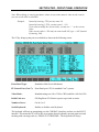
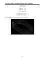
SECTION TWO - FRONT PANEL OPERATION
15
16
17
18
Spindle override and direction: The position of the spindle override and the resulting rpm
(if there is no spindle encoder) or the actual rpm (if there is a spindle encoder). This line
also displays whether the spindle is off or running CW or CCW.
The spindle load meter will show the load on the spindle. It becomes longer and changes
color from blue to green to yellow to red as the load increases.
Coolant, Off, Mist, Flood or Mist/Flood
The Parts Counter increments each time a program ends normally. It will not increment if
a program is aborted, or if there is an error in the program. It does not increment in dry
run, verify or MDI. It does increment on RUN, DNC-Run and DNC-Fast. The parameter
number used for the counter is P699 (you can use this for engraving or what ever you
choose). You can zero, increment or decrement the counter using:
Shift-F1 (zero/reset)
Shift-F2 (decrement) (it will not decrement below zero)
Shift-F3 (increment)
You have to push and hold the Shift while pressing the F key.
The remainder of this section will explain each function that can be executed from the front
panel.
F1 (Home) Main-Home
Following a power off sequence, the control will always have to be homed after the machine has
been reset. Each axis will seek a home limit switch and a marker pulse on the encoder. After this
procedure is finished, the machine's reference position will be established and will be recalled
until another power off. To initiate a home sequence, push ESC until the main screen is reached
and then push F1 (Home). A message requesting that the Cycle Start button be depressed will
appear on the screen and will start flashing. Pressing Cycle Start will start the home sequence,
and when it is finished the main screen will return. Homing parameters may be adjusted in the F4
(Axis) section.
F10 (Here) Home-Here
F10 (Here) is only active if the correct password has been entered in the setup parameters.
The machine can be homed without moving the axis. Toggle the F10 (Here) key when the key is
lit and push Cycle Start. The position of the machine will be assumed as home zero. This action
is useful in that it allows jogging, handwheeling, or MDI’ing without physically homing first. It
is not recommended you run programs unless the machine is homed in the normal fashion as the
software limits will not be valid after F10 (Here).
Note: If the machine has a glass scale used for quill feedback, the F1 (Quill) will zero the quill
position . See page 50, Section 2 for more information on the quill scale.
15
SECTION TWO - FRONT PANEL OPERATION
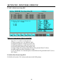
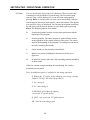
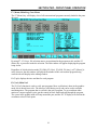
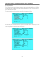
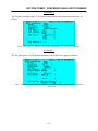
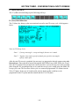
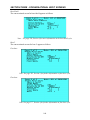
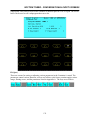
F2 (JOG) Main-Jog
The machine must be homed prior to jogging.
F2 (Jog) is used to move the machine around in a manual mode to pick up zeros and align parts.
Upon pressing F2 (Jog) the following screen appears.
Note: F5 and F6 can be changed to store the positions in the G92 floating zero offset.
The function keys across the bottom of the screen select the desired jogging mode. The F1
(Slow) key selects slow jog. The feed override is active and speeds up or slows down the jog
speed. The F2 (Fast) key selects rapid jog. The machine tool builder determines the slow and
rapid feedrates and has the ability to change the values for each in the axis parameters. The F3
(↔) key selects the continuous jog mode. The jog defaults to continuous each time F3 (↔) is
depressed. In continuous jog, the selected axis continues moving until the user releases the axis
key or encounters the software limits. In incremental jog, the axis moves the selected increment
and then stops each time the user presses and releases an axis key. After the operator presses the
F4 (Dist) key, the control prompts the user to enter the desired amount of increment. The
keyboard diagram displays the direction in which an axis moves when the corresponding key on
the numeric keypad is pressed. To exit the incremental jog mode, the user depresses F3 (↔).
Depending upon the value of the miscellaneous parameter “use FLZ instead of G54", the F5 and
F6 keys perform either a G54 or a G92 for X or Y at the current machine position. This can be
thought of as call this position "##.####". The F7 key is used to set tool lengths; the operator is
prompted for the Z-axis position. If the user desires to leave the jog mode, pushing the ESC
(Exit) key exits the jog mode and returns the control to the main screen.
16
SECTION TWO - FRONT PANEL OPERATION
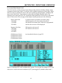
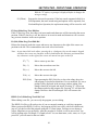
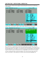
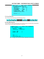
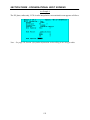
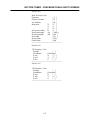
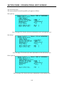
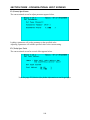
F3 (HDW) Main-HDW
The machine must be homed prior to handwheeling.
The handwheel mode is used to move the machine around using the electronic handwheel. Its
main use is for setting tool length offsets, setting work offsets, and aligning parts. Upon pushing
F3 (HDW) the following screen will appear.
Note: F8 can be changed to store the positions in the G92 offset.
The F keys across the bottom of the screen are used to select which axis will move when the
handwheel is turned. The feedrate override switch will determine the distance each axis will
move for one click of the handwheel. The highlighted axis key determines which axis will move.
F6 (ZTool) is used to set a Z tool length offset into the tool table or H parameter table. In the
handwheel mode, a tool could be put into the spindle and moved to its Z zero point. The F6 key
can then be pushed indicating that we wish to enter the current Z position as a tool length offset
H parameter. The CNC will prompt for a Z position. When the Enter key is pushed, the current
Z position will be used for the tool length.
Depending on the value of the miscellaneous parameter "use FlZ instead of G54". The F8 key
performs either a G54 or a G92 for X or Y or Z at the current machine position. The operator is
prompted for the axis position. This can be thought of as a "call this position '##.####'".
Note: The distance shown is how far the machine will move per click of the handwheel.
17
SECTION TWO - FRONT PANEL OPERATION
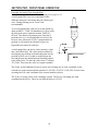
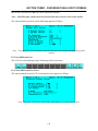
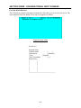
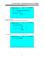
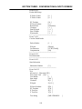
Procedure for Setting Tool Length Offset
Note: there is an alternative method for setting tool lengths on 31.
A tool length offset is used to compensate for the
difference between Z axis home and part surface (part
zero). Setting floating zero in Z axis is not
recommended.
To set tool length offset, load tool #1 in the spindle by
doing an MDI→ T1M6. Use handwheel or jog to touch
the tool on the part at a known location. Select F6
(ZTool). The control will prompt you to enter the Z
position to be set. A tool length offset for tool #1 has
been set. Now when tool #1 (H1) is programmed to a
position, it will position in reference to part zero.
Repeat this procedure for each tool.
A tool length offset can also be set by entering a value
into a tool offset table. The value can be measured by
touching the part with the tool and reading the current
position of the Z axis. If a shim is used between the
tool and the part, the shim dimension should be added
to the offset value. To enter the value select F7 (Parms)
-F3 (Tool). Then enter the value as a negative number.
The F8 key on the handwheel screen is used to set a floating zero or work coordinate on the
selected axis at the current machine position. F8 (G54-X), F8 (G54-Y), F8 (G54-Z) is the same
as setting the G54 work coordinate to the current machine position.
The F9 key is used to select work coordinate systems. The F9 key will change the work
coordinate on the F8 key. There are six different choices, G54-59.
18
SECTION TWO - FRONT PANEL OPERATION
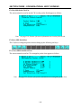
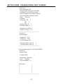
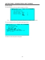
Procedure for Setting a Work Offset
A work offset shifts the X and Y axis zero positions to a desired place (edge of the part). Thus a
part can be programmed from its part zero. To find and set a work offset, refer to the example.
Using a ½" diameter edge finder in the X axis, handwheel or jog to the edge of the part and
depress F8 (G54-X). Establish whether the edge finder is positive or negative from the desired
zero. Enter -.25 for the X position. The current position will read X -.25. Repeat this procedure
for the Y axis.
To check a work offset zero, select F5 (MDI), type G0 (rapid move) X0 Y0 (X and Y position to
0). Press Enter, then Cycle Start. Machine will position to the current work offset.
Caution:
Machine will move in rapid mode. The tool should be above all parts, vises,
etc.
For more information on floating zero, see page 294, Section 4.
19
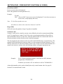
SECTION TWO - FRONT PANEL OPERATION
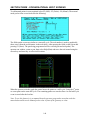
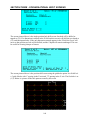
F4 (Run) Main-Run
(The machine must be homed prior to running a program)
The F4 (Run) key is used to execute the active program. Upon depressing the F4 (Run) key, the
following screen appears.
After the above screen appears, F1 (Start) must be pushed and the following screen will appear.
(Note: if the machine is equipt with an automatic tool changer, the operator will be requested to
verify the tool number that is in the spindle)
F1 (First) is automatically selected when this screen is displayed. Therefore, if one desires to run
the active program from the beginning, one need only depress Cycle Start. If F2 (Block) is
20
SECTION TWO - FRONT PANEL OPERATION
pushed, the control will request that the desired block or sequence number be typed in, followed
by Enter. If Cycle Start is depressed, the active program will start running from the selected
block number. If F3 (Tool) is depressed, the control will request a tool number. After typing the
tool number followed by an Enter, Cycle Start is pressed, and the active program will start
running at the desired tool number and the following screen will appear.
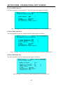
Note: If the block number or tool number requested is not found in the active program, the
following window will appear.
Cycle Start will start the program from the beginning.
This screen is the basic run screen with two new additions: a block number display and F9
(Halt). The block number shows the current line being executed as the program runs. The F9
(Halt) key is similar to Feedhold in that when it is pushed the machine will stop. However,
unlike Feedhold, F9 (Halt) also can exit the Run mode and allow a new program to be started.
F9 (Halt/Resum) Main-Run-Halt/Resume
If a program has been halted, the resume feature of the control becomes active. The F9 (Resum)
key will now be displayed on the Run screen. A program can be resumed as long as one of the
following functions is not performed: F9 (Verf), F5 (MDI), F1 (Home), or Emergency Stop. F9
(Resum) is also canceled if any parameters are modified. If no other function is performed, the
21
SECTION TWO - FRONT PANEL OPERATION
axes can be jogged or handwheeled away from the work, the spindle may be turned on/off, and
F9 (Resum) remains active. As long as the Resume is active, the F9 key on the Run screen will
show a Resume function. If the Resume function is selected, the active program will be resumed
at the halted point. First, Z will retract to the tool change position–all the way up–when a
Resume Cycle Start is executed. Second, X and Y will rapid to the halted point. When X and Y
are in position a Cycle Start will be requested. When Cycle Start is pressed, the Z axis will rapid
to the R plane; it will then feed to its previous depth. The program will then start running as if
nothing happened. Feedhold simply stops axes motion until it is pressed again and Cycle Start
is pushed.
F2 (Old) Main-Run-Old
F2 (Old) will allow entry – from the message window – to an existing text program. After the
number has been entered, the control will check the text programs to see if a program by that
number is there. If one exists, that program will become the active program. If not, a message
stating that the program was not found will appear. After pressing the ESC (Exit) key, another
number may be entered.
The F3, F4, F5, and F8 keys on the Run screen set the mode of operation for the program. When
these keys are in a highlighted state, the functions will be active in any program currently
running or in any program to be executed.
F3 (Block) Main-Run-Block
When the F3 (Block) switch is activated, the program will stop at the end of each block. Each
time Cycle Start is pushed, one more block will be run.
F4 (OStop) Main-Run-OStop
When the optional stop switch F4 (OStop) is activated, the program will stop at each M01
command. When Cycle Start is depressed, the program will continue to run.
F5 (BSkip) Main-Run-BSkip
When the block skip switch F5 (BSkip) is activated, the program will skip all blocks starting
with a / (slash).
Example: / M5
When the block skip switch is active, M5 (spindle off command) will not be executed.
22
SECTION TWO - FRONT PANEL OPERATION
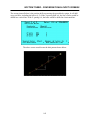
F6 (Displ) Main-Run-Displ
The F6 (Displ) key can be accessed from a number of screens. The following screen is shown as
though the F6 (Displ) was entered from the RUN screen. All the display functions and screens
are identical, independent of the entry point. Only the return point differs based on the original
entry point. When the F6 (Displ) key is depressed, the following screen will appear.
Note: F7 and F9 only come up in protected modes.
F1 (Dist) Main-Run-Displ-Dist
When the F1 (Dist) key is activated, the display shows the current position, next position, and the
distance to go.
23
SECTION TWO - FRONT PANEL OPERATION
F2 (Error) Main-Run-Displ-Error
The Following Error refers to the lag in the servo system.
The F2 (Error) key changes the display to read current position, next position, and Following
Error. The Following Error display is intended to help in machine setup or troubleshooting an
axis problem. When F2 (Error) is pressed, the following screen will appear.
F3 (Graph) Main-Run-Displ-Graph
If F3 (Graph) is pressed, the control switches from displaying text to a graphic display of the
active part program. The following screen will appear.
24
SECTION TWO - FRONT PANEL OPERATION
The graphics on this control are full 3D and will be displayed in the graphics area as long as the
control remains in the Graph mode. When other displays are requested, windows will appear in
the graphics area showing the requested data. When these functions are finished, the windows
will disappear and the graphic display will be reinstated. The scales at the bottom and left side of
the screen are to be used as a reference for the part size. As the screen scale is changed, the
graduations on the rulers will change accordingly. The ruler graduations are in machine units; on
inch system the largest graduations equal approximately one inch. In metric the largest
graduations are 10mm. The Runtime at the top of the screen is basically a stopwatch that starts
when a Run Program command is executed and stops at the end of program or when the program
is aborted. The total job time is kept in program parameter #369 “Job Time”.
The next section will explain how to manipulate the part displayed in the graphics area. All the
following functions are accessible through the Displ-Graph screen.
Note: The graphics are cleared from the display at the start of running or verifying a program.
F1 (Rot) Main-Run-Displ-Graph-Rot
When the display rotate function F1 (Rot) is selected the following screen is displayed.
(F1 -XY, F2 -XZ, F3 -Y2, F4 -ISO)
The F1, F2, F3, and F4 keys give the four standard rotations of a part: XY top, XZ front, YZ
side, and isometric views. The orientation index in the lower left corner of the screen shows the
current part orientation. Depressing the F1 thru F4 keys moves the orientation index to its new
position. The F5 thru F10 keys are used to rotate any of the selected axes in 5° increments.
Again, as the key is pushed, the orientation index rotates indicating the orientation of the part
display. F5 and F6 rotate X axis ±, F7 and F8 rotate Y axis ±, and F9 and F10 rotate Z axis ±.
25
SECTION TWO - FRONT PANEL OPERATION
Note: The display is auto-scaled when the new orientation is displayed.
F2 (Pan) Main-Run-Displ-Graph-Pan
The F2 (Pan) key selects the pan function, which allows the operator to pan around a part. The
following display will appear.
The crosshair which appears on the screen can be moved around using the numerical keys or
arrow keys F7 thru F10. To pan, move the cursor to the point on the display that is the desired
center of screen and push F5 (Enter), or Enter on the keyboard. The display will shift to its new
position and panning may resume. The ESC key will cancel the pan function and return to the
Graph screen.
26
SECTION TWO - FRONT PANEL OPERATION
F3 (Wind) Main-Run-Displ-Graph-Wind
The F3 (Wind) key selects the window function which allows the operator to window in on a
particular area of the part. The following display will appear when F3 (Wind) is selected.
The crosshair which appears on the screen can be moved around using the numeric keys or arrow
keys F7 thru F10 (the same as pan). To zoom in using a window, move the cursor to the first
corner of the window area and depress F5 (Enter) or Enter. Then move the cursor around until
the desired area of the part to be viewed is enclosed in the rectangular box being drawn on the
screen. Next, press Enter. The area enclosed in the box will now be displayed on the entire
screen. After depressing Enter to window on the part, window cancels itself and returns to the
graphic screen.
The X Y coordinates on the lower left side of the screen indicate the position of the cursor,
relative to part zero. The X Y coordinates on the lower right side of the screen indicate the size
of the window. These numbers can be used as a quick reference of the part size and dimensions.
F4 (Auto) Main-Run-Displ-Graph-Auto
The F4 (Auto) key selects the auto zoom function. This function automatically scales and centers
all machine parts on the screen.
F5 (Zoom-) Main-Run-Displ-Graph-ZoomThe F5 (Zoom) key selects the zoom- function which decreases the size of the part currently
being displayed on the screen by half. Generally, this function is used to view a larger portion of
the part.
27
SECTION TWO - FRONT PANEL OPERATION
F6 (Zoom+) Main-Run-Displ-Graph-Zoom+
The F6 (Zoom) key selects the zoom+ function which doubles the size of the part being
displayed on the screen. Generally, this function is used to enlarge a specific area of a part
enabling the operator to see greater detail.
F7 (Limit) Main-Run-Displ-Graph-Limit
The F7 (Limit) key draws a box on the screen which corresponds to the axis limits of the
machine. This allows viewing of the part in relation to the machine's overtravels. If the part
extends beyond this box, it cannot be run on the machine unless some corrective action is taken
to change the work offsets. The axis overtravel limits are set from the parameter screens. If the
tool is programmed outside this box, an “axis software limit overtravel” error will result.
Note: Part zero and tool length must be set to show true position within limits.
F8 (Zone) Main-Run-Displ-Graph-Zone
The F8 (Zone) key draws a box on the screen which corresponds to an axis safe zone. This is a
zone which the tool cannot enter. If the tool is programmed into this box with the safe zone
turned on (G23), an "attempted to move into safe zone" error will be generated. G22 shuts off the
safe zone.
F9 (Coord) Main-Run-Displ-Graph-Coord
The F9 (Coord) key draws an axis coordinate through X0, Y0, Z0. This give a visual reference to
where the zero is on the part.
F10 (Fresh) Main-Run-Displ-Graph-Fresh
The F9 (Fresh) key redraws the currently displayed part on the screen.
Help (Clear) Main-Run-Displ-Graph-Clear
The F10 (Clear) key clears the current display buffer. After the clear screen command is
executed nothing will be displayed until either the program is verified or run again.
F4 (Diag) Main-Run-Displ-Diag
The F4 (Diag) key is mainly used for machine setup or troubleshooting machine functions. The
diagnostic screens bring up all the external I/O bits connected to the CNC. The status of each bit
is continuously displayed on the screen, and as they change on the machine, the screen will be
updated. Function keys F1 thru F5 display the various axes enabled on the CNC. Selecting X, Y,
Z, etc. brings up the appropriate axis I/O channels. A "0" displayed on the screen means the I/O
channel is not active. A "1" indicates active.
28
SECTION TWO - FRONT PANEL OPERATION
The following screens represent the displayed information for the various axis selections.
Note: The diagnostic screens will differ for machines that have varying options. The text that
shows up on the screen is from the files INP.XXX and OUT.XXX, where XXX is the extension for
the desired language to display on the screen. The INP.XXX and OUT.XXX files for a basic
machine with no options are present in the ROM directory. The files that correspond with the
options that a machine might have will be present in the RAM directory. The control will first
check the RAM directory. If the files are not found in the RAM directory, the control will use the
default files in the ROM directory.
Each axis has inputs and outputs, pressing F1…F6 will show the inputs and outputs for the
associated axis.
Note: Machines with tool changers, etc. will have different diagnostics screens.
F7 (OBS) Main-Run-Displ-Obs
The F7 (OBS) key will only display in access level 2 or greater. F7 (OBS) will be highlighted
and is only available if the current display is F1 (Next), F2 (Dist), or F5 (Error). It will display
information on the motion control cards. F7 (Obs) comes up in protected modes only.
F9 (Shell) Main-Run-Displ-Shell
F9 (Shell) is available if the control is in access level 2 or greater. It will Shell out to DOS. To
return to the CNC, type exit. F9 (Shell) comes up in protected modes only.
29
SECTION TWO - FRONT PANEL OPERATION
F7 (Menu) Main-Run-Menu
The F7 (Menu) key selected from the Run or Verify screen brings up a window containing a
listing of all the available programs, which may be run. The screen shown below will be displayed when the program menu is requested.
To activate one of the programs listed in the window, use the arrow and page keys to move the
cursor to the desired program and press F5 (Enter), or Enter on the keyboard. The Menu
function can be called from other screens but works the same way from all. When called from
the Run or Verify screen, the selected program becomes the active program. When called from
an edit screen, the selected program becomes the current program being edited. F1 (Verf) will
graphically verify the part the curser is on. F6 (Togle) will display the file size, last time and date
it was edited, and seven characters for the file name. Subdirectories are specified by <DIR> as
the file name. The “..” specifies the parent to the current directory. If you press the HELP (Drive)
key, a list of the available drives is displayed.
Note: The file name is enclosed in parentheses. If there are no parentheses on the first block,
the file name is the first block. Pressing the “D” key toggles the menu to and from “Full Dos
Filenames”. Pressing the “N” key toggles sorting files by filename and file description.
F8 (Dry) Main-Run-Dry
When the F8 (Dry) is active, all program feedrates will run at the dry run feedrate.
Note: The spindle commands can be ignored during dry run by setting a parameter.
Switching to or from Dry Run cannot be done if the program is running. The machine must first
be F9 (Halt)ed, switched to or from F8 (Dry) Run, and then F9 (Resum)ed. The F8 (Dry) key
will not be visible if the program is running.
30
SECTION TWO - FRONT PANEL OPERATION
F10 (HDW) Main-Run-HDW
When the F10 (HDW) key is activated, the axis moves in the program will relate to turning the
electronic handwheel. The feedrates (feed/rev. or feed/min.) will effect the distance moved per
click of the handwheel. The four miscellaneous parameters that effect the distance moved per
click of the handwheel are listed below.
1.
Handwheel Encoder PPU
Pulses per rev of the electronic handwheel. This should be 400 for our current systems.
2.
Cranking Minutes/Rev
Total minutes of normal program execution time should correspond to one turn of the
handwheel. Multiplying an IPM feed by this factor results in an IPR feed (inches per turn
of the handwheel). This should be about 0.0010 for our current system.
3.
Cranking Max IPM
This limits the feedrate while hand-cranking to get reasonable response at slow
programmed feedrates. Adjusting the other handwheel parameters can give excess errors
on rapids above 100 IPM. It should be about 100 for our current system.
4.
Cranking Factor
The multiplier for each handwheel click should be about 100 for our current system.
Cranking Factor/Cranking Mins Per Rev is proportional to the max feedrate allowed while handcranking.
If handwheeling and dry running a program, the distance moved per click of the handwheel
relates to the Dry Run Feed parameter.
When switching from the handwheel mode to automatic mode, the operator will be prompted to
press cycle start.
If operator is handwheeling a program and a tapping cycle is started, the message "Tapping cycle
will not be in handwheel mode. Press any key to continue" will appear. The machine will tap the
hole and return to the handwheel mode.
Help (TlSet) Main-Run-TlSet
When no program is running, the Help (TlSet) key will be the tool setting key. Help (TlSet) is
similar to F1 (Start). When pressed, a Cycle Start will be requested.
1.
2.
3.
4.
5.
The operator is prompted for the height of the setting gauge.
The operator is prompted for the tool number to set the offset. The machine does a
tool change to this tool number.
Operator handwheels the tool tip to the gauge or face of the part. He then presses
Enter.
Operator is prompted for the tool radius.
Go to number 2.
31
SECTION TWO - FRONT PANEL OPERATION
During the tool setting routine, the tool table is loaded with the appropriate values. After all the
tool offsets are loaded, the operator can press ESC (Halt) to exit the tool setting routine.
Note: This routine can be modified for specific applications (auto tool setters, different tool
changers etc.).
F5 (MDI) Main-MDI
The F5 (MDI) key on the Main menu selects the MDI (manual data input) function. Through
MDI any programmable machine function can be executed one function or one block at a time.
When MDI is selected the following screen appears.
As the functions are typed in they will appear on the MDI line at the bottom of the screen. After
the data has been typed in, Enter must be pressed to end the block. At this point a Cycle Start
will execute the MDI line. During MDI the ESC (Esc) key will terminate any MDI command. F6
will bring up the normal graphic displays discussed earlier. If graphics are turned on during
MDI, the graphic display will graph all the MDI moves as they are executed.
F1 (Gcode) Main-MDI-Gcode
F1 (Gcode) will bring up a list of legal G codes with a short description of each code. Pressing
the F1 (Gcode) key will bring you to the next page of G codes.
00 Linear Rapid
02 CW Arc
04 Dwell
10 Set Data Mode
12 Clear Floating Zero
18 XZ or ZX Plane
01 Linear Feed
03 CCW Arc
09 One-Shot Exact Stop
11 Clear Data Mode
17 XY Plane
19 YZ Plane
32
SECTION TWO - FRONT PANEL OPERATION
20 English
22 Safe zone check off
24 Circ Pocket Clear
26 Circ Finish Outside
29 Return From Ref
31 Z to Clearance
33 Facing Cycle
35 Rect Finish Inside
39 Threading Cycle
41 Left CutterComp On
43 + H Offset Dir
45 Left Auto Comp On
47 Auto Comp Off
50 Scaling Off
52 Local Coordinate
54 Worksystem 1
56 Worksystem 3
58 Worksystem 5
60 One-Shot Rapid Move
63 Tapping Mode On
65 Move Lockout Block
69 Rotation Off
71 Mirror Image On
73 Woodpecker Drill
76 Fine Bore
80 Canned Cycle Cancel
82 Drill/Dwell
84 Tap
86 Fast Bore
88 Hard Tap (option)
90 Absolute
92 Set Floating Zero
94 Inches per Minute
98 Ret to Initial Level
21 Metric
23 Safe zone check on
25 Circ Finish Inside
28 Reference Return
30 2nd-4th Ref Return
32 Z to Tool Change
34 Rect Pocket Clear
36 Rect Finish Outside
40 CutterComp Off
42 Right CutterComp On
44 - H Offset Dir
46 Right Auto Comp On
49 Cancel Tool Offsets
51 Scaling On
53 Machine Coordinates
55 Worksystem 2
57 Worksystem 4
59 Worksystem 6
61 Exact Stop Mode
64 Tapping Mode Off
68 Rotation On
70 Mirror Image Off
72 Bolt hole
74 Left Tap
78 Manual Bore
81 Drill
83 Peck/Drill
85 Bore
87 Back Bore
89 Bore/Dwell
91 Incremental
93 Inverse Time Feed
95 Inches per Revolution
99 Return to R-plane
Note: The text file that displays the legal G codes on the screen is Gcodes.XXX, where XXX is the
extension for the corresponding language. The control first looks for Gcodes.XXX in the RAM
directory. If not found, it then searches the ROM directory for the file.
F2 (Mcode) Main-MDI-Mcode
F2 (Mcode) will bring up a list of legal M codes with a short description of each code.
00 Program Stop
02 End of Program
04 Spindle On CCW
06 Tool Change
01 Optional Stop
03 Spindle On CW
05 Spindle Off
07 Mist On
33
SECTION TWO - FRONT PANEL OPERATION
08 Flood On
30 Spindle Off, End of Program
91 Graph On
94 3D Sweep On
96 Rounded Wall
98 Call Jump
09 Coolant Off
90 Graph Off
93 3D Sweep Off
95 Tapered Wall
97 Pocket Clear
99 End of Program
Note: The text file that displays the legal M codes on the screen is Mcodes.XXX, where XXX is
the extension for the corresponding language. The control first looks for Mcodes.XXX in the
RAM directory. If not found, it then searches the ROM directory for the file. Depending upon the
machine options, the legal M codes will vary. The Mcodes.XXX in the ROM directory is for a
basic machine with no options.
F6 (Displ) Main-Displ
See explanation under F6 (Displ) Main-Run-Displ on page 23, Section 2. This function can be
entered from either screen.
F7 (Parms) Main-Parms
The F7 (Parms) key from the main screen brings up the following parameter screen.
34
SECTION TWO - FRONT PANEL OPERATION
F1 (Setup) Main-Parms-Setup
The F1 (Setup) selection brings up the parameters, which make the control unique to a particular
machine or application. When F1 (Setup) is selected the following screen appears.
Note: F2 (Prec) through F9 (DOS) are only displayed if the control is in the protected mode set
by a validation code.
The CNC requires a VALIDATION CODE and an ACCESS LEVEL number to allow the
machine setup parameters to be displayed or changed. The machine tool builder can supply the
validation code and access level.
35
SECTION TWO - FRONT PANEL OPERATION
Note: The parameters in the setup sections are normally set by the machine tool builder.
Changing these parameters can affect a large number of machine functions and machine
performances and should only be modified by experienced service personnel.
Assuming the proper codes have been entered, the following screens can be selected.
F2 (Prec) Main-Parms-Setup-Prec
If the F2 (Prec) selection for Machine Precision is made, the following screen will be displayed.
Keys displayed in the Edit Mode:
The above screen shows some typical settings for leading and trailing zeroes for the different
coordinate systems. The number of leading and trailing zeroes is unlimited, but some practical
limits do exist. If the numbers get too large, they will not fit on the screen in their allotted space.
If they are smaller than the feedback units, they will not cause movement. To change a parameter
press F1 (Edit). A series of arrow keys will be displayed; use them to move the cursor to the
desired parameter and type in the new number. Once all the numbers have been edited, pressing
the ESC (Exit) key will validate the new numbers and return to the previous screen. These
parameters are for all numbers entered into the control except for the axis parameters, which are
set separately in the F4 (Axis) parameters.
F3 (Power) Main-Parms-Setup-Power
Power parameters are parameters that directly relate to the configuration of the machine tool and
will normally be set by the machine tool builder.
36
SECTION TWO - FRONT PANEL OPERATION
Note: When editing or entering parameter values (or any other numeric value on the control),
you can use the built in calculator.
Example:
Instead of entering .3750 you may enter 3/8
Instead of entering 1.3750, you may enter 1 + 3/8
If you want to modify the current value, you may use “.” as the current
value.
If the current value is .358 and you want to add .002, type .+.002 (instead
of entering .360).
The F3 key brings up the power-on defaults as shown in the following screen.
Front Panel Type:
Standard or Mini-Series Membrane
FP Control Port (Cent 7): Front Panel port 1552 for standard Cent 7 systems
Video Mode:
Standard settings are 640 x 350 for CRTs and 800 x 600 for LCDs
Initial Units are:
G20 English or G21 Metric to power up in inch or metric.
Number of Axes:
Can be 1 to 5.
Serial Keyboard :
Enables or disables serial keyboard
The keyboard will boot up transmitting over the CLK/DATA interface and not over the RS-232
interface. This means the PC will be able to recognize that a keyboard is present upon reset and
not hang with a message such as, <PRESS F1 TO RESUME>. The keyboard will always
37
SECTION TWO - FRONT PANEL OPERATION
recognize commands over either the RS-232 or CLK/DATA interface. Whenever a valid
command with no error is received over the RS-232 interface, it will start transmitting over the
RS-232 interface and not the CLK/DATA interface.
In like fashion, it is possible to switch back to the CLK/DATA interface. Whenever a valid
command with no error is received over the CLK/DATA interface, it will start transmitting over
the CLK/DATA interface and not the RS-232 interface.
Since the RS-232 interface is not as interlocked as the CLK/DATA interface, the following
additional requirements are placed on the RS-232 protocol.
1.
The system is allowed to send commands only in response to transmissions set by the
keyboard.
2.
When the keyboard transmits it will wait for the transmission to be complete and then
delay another two milliseconds before again checking the keystroke buffer. This delay
allows the system time to send a resend command or other command such as turning on a
light. Since transmitting a character takes approximately one millisecond at 9600 baud,
this allows about 1 millisecond processing time for the system.
3.
To allow the system a chance to send out commands, the keyboard will send out a strobe
signal periodically. The strobe signal is simply the character EAh. This character will be
transmitted if the keyboard is otherwise idle for approximately 30 milliseconds. The
system can then send out a command in response to the strobe instead of having to wait
until the next keystroke.
Hardware and Software Requirements
The serial keyboard requires a REV E keyboard controller card with firmware version #1.21 or
greater. Firmware for the REV E cards cannot be used with older revision cards and vice versa.
CNC software must be of version # *.86 or greater.
The serial keyboard uses COM2. Therefore, if the serial keyboard is used, the secondary serial
port parameter should be set to none. The secondary serial port parameter may be removed in a
future version.
On machines set up to use the serial keyboard there will be a revised cable in the mag box.
Previously, the cable coming in was split in two and ran to the video card and to the controller
card. Now the cable will split in three and have a 9-pin D-Sub connector to attach to the I/O card.
The connector on the I/O card should be set up to be COM2 (as shipped to us, it is
usually COM1).
Enabling the Serial Keyboard
The CNC program will use the serial keyboard interface if the power-up parameter Serial
Keyboard is set to Yes and if the program is executed without any command line options.
38
SECTION TWO - FRONT PANEL OPERATION
Alternatively, the CNC program will use the serial keyboard interface if the serial keyboard
parameter is set to Yes and the letter "s" appears as an option on the command line.
The serial keyboard is enabled in the following examples if the serial keyboard parameter is also
set to yes.
CNC
CNC s
CNC fs
CNC as
CNC afs
(serial keyboard only)
(front panel lights, serial keyboard)
(acroloops, serial keyboard)
(same as no options)
The serial keyboard is disabled in the following examples:
CNC n
CNC f
CNC a
CNC af
CNC b
CNC bf
(demo mode)
(front panel lights)
(acroloops)
(acroloops and front panel lights)
(NCB, Cent 6)
(NCB and front panel lights)
Power-On Feedrate:
Can be any number up to the maximum feedrate.
Spindle Axis:
1 to 5 1=X, 2=Y, 3=Z, 4=A . . . etc
Normally set to 3 for Z axis.
Primary HDW Encoder
Axis (Cent 6 and up)
The encoder to use for the primary handwheel.
7 for standard Cent 6 systems, 8 for standard Cent 7 systems.
2nd Handwheel
Encoder Axis:
Used for optional dual handwheel systems (4 if it has the
option).
3rd Handwheel
Encoder Axis:
Used for optional dual handwheel systems (5 if it has the
option).
New remote handwheel:
Yes, if it has the new style remote handwheel option.
Remote HDW Encoder:
The encoder to use for the remote handwheel.
100% Rapid in Run:
No means the feedrate override will affect rapid moves.
Yes means the feedrate override will not affect rapid in the run
mode. Rapid moves are 100%.
39
SECTION TWO - FRONT PANEL OPERATION
100% Rapid in Dry-Run:
No means the feedrate override will affect rapid moves in the dry
run mode.
Yes means the feedrate override will not affect rapid in the dry run
mode. Rapid moves are 100%.
Spindle on in Dry-Run:
No means the spindle will not come on in the dry run mode.
Yes means the spindle will come on in the dry run mode.
Tool Tables by:
Radius or Diameter
Don't Load Canned
Cycles:
No means Canned Cycles will be loaded.
Yes means Canned Cycles will not be loaded; the canned cycles
(drill, pockets, frame etc.) take approximately 39K of RAM.
Block Skip On:
If Yes the block skip will be on at power up.
Optional Stop On:
If Yes the optional stop will be on at power up.
Safe Zone On:
If Yes the safe zone will be on at power up.
G22 turns the safe zone off.
G23 turns the safe zone on.
Foreign Extensions:
Refers to the extension for data files. Current valid extensions are
listed below.
CES
CHN
NED
DAT
FRN
GRM
ITA
SPN
TRK
CZECH
CHINESE
DUTCH
ENGLISH
FRENCH
GERMAN
ITALIAN
SPANISH
TURKISH
Tool Changer Information
Machine Type :
Type in VMD 30....
ATC Type is:
Manual/Avanti, Milltronics, or other
ATC tool (pocket count):
Number of pockets on the tool changer
Spindle orient delay(MS): Time delay for orient pin (use 0 for roller pins, or electronic orient)
M6 (Tool Change) Macro: Path and Name of the program used for custom M6
40
SECTION TWO - FRONT PANEL OPERATION
Put Pot down on
swing arm tool changers:
Yes means the pot will be down for the pending tool.
No means it will be up.
Check drawbar switch:
Yes for newer machines with drawbar switches.
Milltronics ATC is:
Plunger, Geneva Two-Step, Geneva One-Step or Swing Arm
Milltronics CW Coast:
Milltronics CW Brake:
Milltronics CCW Coast:
Milltronics CCW Brake:
Partner 1 Geneva tool changers use these
Parameters to set the times to index and
brake the tool changer in the CW and CCW
directions. Suggested values are 110 for coast and 60 for brake.
Check Air Pressure:
If the parameter is set to yes and the pressure is low (Y input #1),
the machine will emergency stop and error 448 “Air Pressure
Error. Check air hose connection” will occur.
Drawbar Delay:
Used in the Partner tool changers as a delay (in seconds) after the
drawbar comes on and before the head goes up to remove the tool
to prevent pulling on the tool holder.
Custom M and G code Tables
Custom G code O9010
Custom G code O9011
Custom G code O9012
Custom G code O9013
Custom G code O9014
Custom G code O9015
Custom G code O9016
Custom G code O9017
Custom G code O9018
Custom G code O9019
Custom M code O9020
Custom M code O9021
Custom M code O9022
Custom M code O9023
Custom M code O9024
Custom M code O9025
Custom M code O9026
Custom M code O9027
Custom M code O9028
Custom M code O9029
Cannot have a custom G code for G0
Cannot have a custom M code for M0
41
SECTION TWO - FRONT PANEL OPERATION
Parameter file version:
Should always be 1
Use Small Soft keys:
Should be set to no for 12" CRT monitors
Notes on Parameters
Note 1:
To change a parameter, press F1 (Edit) and type in the new number.
Note 2:
After changing any power parameter, return to the main menu before cycling power.
Note 3:
After any power parameter is changed, the machine must be powered down, then up
again. These parameters are only read on power up.
F4 (Axis) Main-Parms-Setup-Axis
If the F4 (Axis) key is pressed, the following screen will be displayed.
Keys displayed when F1 (Edit) is pressed:
The PgUp, PgDn, and arrow keys move through the tables on the upper display. The lower
display changes to show the data associated with the cursor position of the upper display. To edit
the values in these tables the cursor is positioned using the arrow keys to the desired parameter in
the upper screen. When the F1 (Edit) key is pressed the cursor will move to the lower screen.
Next, move the cursor using the arrow keys to the axis or parameter desired and type in the new
values using the keypad. After the new values have been entered, press the ESC (Esc) key. The
new value will be entered and the cursor will return to the upper screen; the selection process
42
SECTION TWO - FRONT PANEL OPERATION
may then recommence. Some parameters can be related to the machine position. To edit or load
these parameters, use F4 (Mach) to load the X, Y, and Z positions into the parameters. Use the
F5 (M-XY) for the X and Y axis or the F6 (M-Z) key for the Z axis. The following is a list of all
the selectable parameters displayed in this mode and a description of their functions.
Axis Address Label
X 88.0000
Y 89.0000
Z 90.0000
Pulses Per Unit
X 10000.0000
Y 10000.0000
Z 10000.0000
ASCII code assigned to each axis
The number of pulses the feedback
gives per unit of travel
Encoder Multiplier
X 02.0000
Y 01.0000
Z 01.0000
Sets an internal multiplier on the
number of pulses coming from the
encoder. 0 is times 1, 1 is times 2, and 2 is times 4
Home Position
X 00.0000
Y 00.0000
Z 00.0000
The dimension assigned to the
machine zero or home position
Home Direction
X 00.0000
Y 00.0000
Z 00.0000
Defines the direction of rotation of the motor
when a home is commanded
CW = 00.0000
CCW = 01.0000
Velocity Toward Home
X 60.0000
Y 60.0000
Z 60.0000
Sets the feedrate at which an axis
seeks the home limit switch
Velocity Away From Home
X 12.0000
Y 12.0000
Z 12.0000
Sets the velocity at which an axis
feeds off the home limit switch
Velocity Toward Marker
X 02.0000
Y 02.0000
Z 02.0000
Sets the velocity at which an axis
searches for the encoder marker pulse
43
SECTION TWO - FRONT PANEL OPERATION
Home Sequence
X 02.0000
Y 02.0000
Z 01.0000
These numbers determine
the order the axes will home in:
#1 first, #2 next, etc. Axes with
the same number home together. 0 will
cause that axis to not home.
Positive Limit
X 00.0000
Y 00.0000
Z 00.0000
Dimension from machine zero where
the positive software limit occurs
Negative Limit
X -31.0000
Y -18.0000
Z - 6.5000
Dimension from machine zero where
the negative software limit occurs
Maximum Feed
X 200.0000
Y 200.0000
Z 200.0000
Sets the maximum G01 feedrate in
inches per minute or mm per minute
Dry Run Feed
X 75.0000
Y 75.0000
Z 75.0000
Sets the dry run feedrate in inches
per minute or mm per minute
Rapid Velocity
X 800.0000
Y 800.0000
Z 800.0000
Set the maximum G00 feedrate in
inches per minute or mm per minute
Feed S-Curve Acc
(Cent 7 and up)
The units are identical to the (linear) acc/dec. These ramps
are used when the s-curves are enabled in feed moves.
Rapid S-Curve Acc
(Cent 7 and up)
The units are identical to the (linear) rapid acc/dec. These
ramps are used when the s-curves are enabled in rapid
moves.
Acc/Dec
X 20.0000
Y 20.0000
Z 20.0000
The Acc/Dec is a number that determines the rate at
which the axis velocity is increased or decreased for
feed moves. The smaller the number the longer the
Acc/Dec times will be. Acceleration and deceleration in
this control are linear ramps. Units are in inches per sec².
44
SECTION TWO - FRONT PANEL OPERATION
Rapid Acc/Dec
X 20.0000
Y 20.0000
Z 20.0000
The Rapid Acc/Dec is a number that determines the
rate at which the axis velocity is increased or
decreased for rapid moves. The smaller the number
the longer the Acc/Dec times will be. Acceleration and
deceleration in this control are linear ramp units and are in
inches per sec².
Feed S-Curve Acc
(Cent 7 and up)
The units are identical to the (linear) acc/dec. These ramps
are used when the s-curves are enabled in feed moves.
Rapid S-Curve Acc
(Cent 7 and up)
The units are identical to the (linear) rapid acc/dec. These
ramps are used when the s-curves are enabled in rapid
moves.
Slow Jog Velocity
X 50.0000
Y 50.0000
Z 50.0000
Velocity in IPM or MMPM
Fast Jog Velocity
X 200.0000
Y 200.0000
Z 200.0000
Velocity in IPM or MMPM
Jog Key Direction
X 00.0000
Y 00.0000
Z 00.0000
Sets whether the Jog is related to moving the table or
moving the tool. A “1" reverses the direction
In Position
X 00.0050
Y 00.0050
Z 00.0050
After any rapid move, the machine will wait until all
axes are within position to the destination before
starting the next block
G00 Unidirectional
X 00.0000
Y 00.0000
Z 00.0000
Sets the distance in inches or mm which an axis will
go past the destination point in one direction before
reversing direction so that the machine will always
position from the same direction. Active only in G00 mode.
P1
P2
Uni-distance
45
SECTION TWO - FRONT PANEL OPERATION
G60 Unidirectional
X 00.0000
Y 00.0000
Z 00.0000
Same as G00 unidirectional except only active in a
G60 block
Backlash
X 00.0000
Y 00.0000
Z 00.0000
Sets the distance in inches or mm. The control will
compensate for lost motion whenever an axis
reversal takes place. Active in all modes.
Excess Error
X 00.2500
Y 00.2500
Z 00.2500
Sets the distance in inches or mm. The machine can
lag behind the CNC. The CNC will shut the system
down due to an excess following error.
00.0000 = will never force an excess error.
Rotary=0 Linear=1
X 01.0000
Y 01.0000
Z 01.0000
Sets whether an axis should be treated as rotary or
linear. In rotary, the feedrate is interpreted as
degrees per minute rather than inches per minute.
There is no conversion between inch and metric for rotary
axis.
Handwheel Normal=0 Invert=1
X +00.0000
Y +00.0000
Z +00.0000
A “1" will reverse the direction of the handwheel.
English Leading
X 02.0000
Y 02.0000
Z 02.0000
Sets the number of characters to the left of the
decimal point for the inch system, for the specified
axis only
English Trailing
X 04.0000
Y 04.0000
Z 04.0000
Sets the number of characters to the right of the
decimal point for the inch system, for the specified
axis only
Metric Leading
X 03.0000
Y 03.0000
Z 03.0000
Same as English Leading except for the metric case
Metric Trailing
X 03.0000
Y 03.0000
Z 03.0000
Same as English Trailing except for the metric case
46
SECTION TWO - FRONT PANEL OPERATION
Home Switch=0 Marker=1
X 00.0000
Y 00.0000
Z 00.0000
Sets whether an axis will seek a home limit switch
and then the marker pulse, or just seek the
nearest marker pulse.
Max Handwheel Error
X 01.0000
Y 01.0000
Z 01.0000
When the excess error reaches this value, pulses
from the handwheel are ignored. Error is specified in
inches or mm.
Tool Change
X + 00.0000
Y + 00.0000
Z + 00.0000
Z moves to this location on a G32 (Z to toolchange)
or M6 (toolchange) command. This position is specified
in inches or mm and is relative to the home zero. The Y
axis tool change position is used on bridge mills. X and Y
are used on Pick-n-Place Tool Changers
Tool Changer Spacing (arm style) Use to avoid large tools being place next to each other on
arm style tool changers
Gain Proportional (KP)
X + 08.0000
Y + 08.0000
Z + 08.0000
KP is in units of DAC steps per count of following
error.
Gain Velocity (KV)
X + 250.0000
Y + 250.0000
Z + 250.0000
KV is in units of DAC steps per unit of velocity. These
units assume a 16 bit (1 bit sign, 15 bits magnitude)
DAC, although the lower four bits are not actually
significant. The units of velocity in this case are
counts/heartbeat, one heartbeat being 3/4096th of a second.
Larger values reduce the following error. Reasonable
values are between 50 and 327.
Handwheel Gain (KP)
X 04.0000
Y 04.0000
Z 04.0000
Same as proportional. Smaller values are used to
soften the handwheel motion. Reasonable values
are between 2 and 8.
47
SECTION TWO - FRONT PANEL OPERATION
F5 (Misc) Main-Parms-Setup-Misc
The F5 (Misc) key brings up various miscellaneous setup parameters dealing with the spindle
and M codes. When F5 (Misc) is selected, the following screen appears.
Miscellaneous parameters are edited similarly to the Power parameters. The following is a list
and short description of the miscellaneous parameters.
Basic Machine Info
Machine Type
Type in VMD30, etc.
Machine Version
The current model
Mechanical Version
The current mechanical version
Electrical version
The current electrical version
Machine serial number
The machine serial number
Force FP Spindle
Yes for older style Centurion Vs that output the spindle
analog from the front panel.
Check Up to Speed
(M3/M4)
Control will wait for up-to-speed signal from the
spindle controller before continuing on M3 (spindle CW) or
M4 (spindle CCW)
Check Zero Speed (M5)
Control will wait for zero speed signal from the spindle
controller before continuing on M5 (spindle off)
48
SECTION TWO - FRONT PANEL OPERATION
Spindle Encoder PPU1
Pulses per rev of spindle, used for hard tapping option and
displaying the RPM in gear 1
Spindle encoder PPU2
Pulses per rev of spindle, used for hard tapping option and
displaying the RPM in gear 2
Handwheel Encoder PPU
Pulses per rev of the handwheel, should be 400 for current
systems
Spindle Range 1
Max spindle speed for gear 1
Spindle Range 2
Max spindle speed for gear 2
.
.
.
Max spindle speed for gear 8
Spindle Range 8
Spindle Range
Which range the spindle is in: 1 to 8. Scaled assumes the
range based on the programmed spindle speed and puts out
the appropriate voltage.
Maximum Spindle Speed
This will clamp the overall spindle speed. It is used to limit
the RPM's in high gear while still getting a large range of
speeds in lower gears.
Spindle Ramp Time 1 (sec)
The tapping deceleration point is adjusted based on spindle
RPM, pitch, and spindle ramp time so as not to overshoot
the programmed depth. It relates to the time in seconds to
decelerate the spindle to 0 RPM’s from full RPM’s in gear
1.
Spindle Ramp Time 2 (sec)
The tapping deceleration point is adjusted based on spindle
RPM, pitch, and spindle ramp time so as not to overshoot
the programmed depth. It relates to the time in seconds to
decelerate the spindle to 0 RPM’s from full RPM’s in gear
2.
2 Gear Yaskawa M5
Spindle Motor
Yes for newer M5 spindle drives with 2 gear spindle
motors. The spindle does not need to stop to shift.
Electronic Spindle Gear
Yes enables the shifting of electronic geared spindle drives.
Spindle Gear Box
Yes for RW30 with a mechanical spindle gear box.
49
SECTION TWO - FRONT PANEL OPERATION
Hard Tap Fudge Factor
Used to adjust the depth of rigid tapping cycle. Higher
numbers will decrease the amount of overshoot at the
bottom of the hole.
Feed Back on Mitutoyo Scale
Yes will enable the Z axis feedback from the Mitutoyo
scale options.
Feed Back on Quill Scale
Yes enables the glass scale for Z axis quill options.
Quill Epsilon
If the value is zero no error checking is done for quill
movement. If the value is none zero, quill motion is
monitored while a program is running. If the quill moves,
the control goes into block mode and an error 666 "Quill
motion detected, return the quill to it's original position –
12.3456" will be displayed. The program will not continue
until the quill is returned to it's original position. The
position of the quill at the start of a program (and during
tool changes) is saved and used to compensate Z positions
during the program.
Quill Scale Encoder
The encoder to use for the glass scale for Z axis quill
options.
Quill Scale PPU
Back Gear Reverse
The pulses per inch for the quill scale encoder.
If the back gear input is sensed and the parameter is Yes,
the outputs for CW and CCW are reversed.
Keyboard Code
015 for systems with a CAT900 card, 0 for others
Yaskawa Drives
Yes, if it has Yaskawa drives (Yaskawa drives give a drive
OK signal instead of a drive fault signal)
Door Open Switch
See notes on European code (page 55) at the end of this
section.
European Code
See notes on European code (page 55) at the end of this
section.
Auger Aux (Cent 7 and up)
The front panel Aux buttons can be assigned to specific
functions. To assign the Aux1 button to the auger enter
"001", to assign the Aux2 button to the setup button enter
"002" in the parameter
Setup Aux (Cent 7 and up)
Door Open Axis
Door Open Input
See notes on European code (page 55) at the end of this
section.
50
SECTION TWO - FRONT PANEL OPERATION
Door Open Override Axis
Door Open Override Input
See notes on European code (page 55) at the end of this
section.
Check Tool Door Open
If Yes, Z input 10 is checked before tool changer arm is
commanded. If the input is not seen in 15 seconds, a
timeout error is displayed.
Check Processor
Temperature
If Yes and the over temperature Z input 4 is
made, an over temp message will be displayed.
Cool-Down Time (Min)
(Cent 6 and up)
Used on spindle air-purge systems.
Lube Cycle Time
(Cent 6 and up)
Used on spindle air-oil lubricating systems.
Recycle Pump Time (Secs)
(Cent 6 and up)
Used on coolant through the spindle systems.
Max Feed w/Door Open
See notes on European code (page 55) at the end of this
section.
Soft Start Delay (Secs)
The time delayed before allowing axis movement after the
machine is reset.
Digital Readout in E-Stop
If Yes the axis position display will be updated even when
emergency-stopped.
Probe Axis and Probe
Input
Designates which axis and input number for the
Probe 1 and Probe 2 commands to use.
Cranking Minutes/Rev
How many minutes of normal program execution time
correspond to one turn of the handwheel. Multiplying an
IPM feed time, this factor results in an IPR feed (inches per
turn of the handwheel). This parameter should be
approximately 0.0010 for our current systems.
Cranking Factor
Multiplier for each handwheel click is approximately 100
for our current systems. Cranking/Factor/Cranking
MinsPerRev is proportional to the max feedrate allowed
while hand-cranking.
Cranking Max IPM
This limits the feedrate while hand-cranking to get
reasonable response at slow programmed feedrates.
Adjusting the other parameters can give excess errors on
51
SECTION TWO - FRONT PANEL OPERATION
rapids. This parameter should be approximately 100 for our
current systems.
Sharp Corners
Yes will cause all corners to be rounded to a maximum
specified by the max corner deviation parameter. No will
round the corners proportionally to the feed rate. Full feed
rate will round the corners by the max corner deviation
parameters. Slower federates will reduce the deviation.
Max Corner Deviation
This number sets the maximum deviation allowed on a
corner. A value of .001 means the machine will slow down
when approaching a corner by more than .001". (Centurion
6 only.)
Min Block Time (sec)
If the time to execute a move is less than this value, the
control will slow the feedrate down in an effort to forestall
jerky motions from data starvation.
End-of-Cycle Axis and
End-of-Cycle Outputs
These two parameters define which output will be
used for the End-of-Cycle Light.
The end of cycle light does not need to be programmed. The light will come on anytime there is
no motion and a program is running and at the end of a program. This would be the case for
block stops, waiting for tool change reset, etc. The light goes off when any key is pressed or
motion recommences. The light may illuminate during dwells, automatic tool changes, orienting,
and etcetera, but it will shut off when the machine recommences motion.
Acc Settling Time (Msec)
Dec Settling Time (Msec)
(Cent 6 and up)
The amount of time to keep the velocity constant after accelerating
or decelerating.
52
SECTION TWO - FRONT PANEL OPERATION
Software Options
Security Code # 0
Secret code to enable S-curves
Use S-curves
(Cent 7 and up)
Yes to enable S-curves for acceleration and deceleration.
Look Ahead
(Cent 6 and up)
Specifies the number of axis moves the control can see ahead,
which enables the control to prepare for sharp corners or features
that could otherwise be rounded off when feedrates are increased.
Note: Look Ahead is only active in DNC-fast mode. Valid values are between 10 and 255.
Max graph file size
Limits the amount of graphics on the screen.
30,000 for standard systems
Minimum Parts Space
If the parts space is less than the parameter value in KB, the system
will go to the erase screen each time a key is pressed on the main
menu.
G18 is
XZ plane (X is the primary axis) or ZX plane (Z is the primary
axis)
G93 is
1/min or 1/sec for inverse feedrates
Special Flags
Normally set to 0
Bit 1 (#1) will place a dot on the graphics screen when plotting the tool.
Bit 2 (#2) will shut off trig help.
Bit 3 (#4) will shut off cutter compensation.
Bit 5 (#16) draws a circular tool in XY plane same diameter as active tool.
Bit 6 (#32) draws a 3-D tool on graphics screen.
Ignore Rapids in
Autoscale
If Yes, rapid moves will be ignored when auto-scaling
the graphics.
Remove Length
from Graphics
If Yes, the graphics will treat all tool lengths as 0.
Screen Blank Time (min)
Time in minutes to blank the screen if no key is pressed
Flat Screen Blank
Yes for CRTs. Some flat screens take too long to refresh if the
parameter is set to Yes.
53
SECTION TWO - FRONT PANEL OPERATION
Use FLZ instead of G54
Used for setting work offset in jog and handwheel mode. Yes
means use FLZ (G92 offsets). No means use G54 offsets.
Tool Setting
If set to any tool the jog and handwheel tool setting routines will
prompt the operator for the tool # being set. If it is set to current
tool the control will assume the active tool # is the one that is being
set.
Tool Setting Use
Work Offsets
If set to No, the position given by the operator is relative to home.
If set to Yes, the position given is relative to the work offset (this is
useful for tool setting off the table and using a Z work offset to the
top of the part).
Extract Input Programs
If set to Yes, the control will extract programs based on 0###'s in
file loaded from the floppy drive or received in RS-232. Duplicate
programs are overwritten without prompting the operator.
P899
Consult factory for special options.
Resolve DNC programs
If Yes, goto's can be used in DNC, Run, or DNC Verf.
Full Dos File Names
If Yes, eleven character DOS file names [FILENAME.EXT] may
be used. Pressing the “D” key on any menu toggles the Full Dos
File Names parameter.
Disable 417 Errors
If Yes, parameters may be modified while a program is running or
verifying. If No, an error 417 will be given when attempting to
modify a parameter while a program is running.
Load Tool Offsets
Set to Yes each time a program is started or when entering MDI.
The tool offsets will default to the values from the tool table for the
current tool. If set to No, the tool length and radius will default to
zero.
Multiple Block Display
If Yes, the current block being executed plus the next seven blocks
will be displayed when programs are running.
CAD Parameters
CAD Type is, DXF, CDL
CAD file type to import in conversational programming.
CAD Epsilon
Tolerance for geometry intersections of imported CAD files.
54
SECTION TWO - FRONT PANEL OPERATION
Post M codes Table
Post M code #0
Post M code #1
Post M code #2
Post M code #3
Post M code #4
Post M code #5
Post M code #6
Post M code #7
Post M code #8
Post M code #9
M codes listed here will be executed
after all other operations within
the block.
Report File
DOS file names to write DPRINT text to when
using POPEN P0
Command Name
Any string in this parameter will show up on the F10 (Util)
key. Pressing F10 will execute the DOS file associated with
the command name. See page 112 for more information on
this feature.
PULSEX pulse delay (MS)
Msec pulse time used with PULSE0 and PULSE1
Spindle Power Raw
Value read from ADC, 0 to 255
Spindle Power Scale
Multiplier to obtain Spindle Power Value
Spindle Power Value (AMPS)
Calculated from the spindle power raw and scale
Spindle Power Limit (AMPS)
Not used
European Code Parameter and Operation Descriptions
Door Open Switch
Enables the door open switch
European Code
Enables the door open button
Door-Open axis
The axis # that the Door-Input-Switch goes into
Door-Open-Input
The input # that the Door-Input-Switch goes into
Door-Open-Override Axis
The axis # that the Door-Open-Override Button goes into
Door-Open-Override Input
The input # that the Door-Open-Override Button goes into
55
SECTION TWO - FRONT PANEL OPERATION
Max Feed with Door Open
The maximum speed the machine can move with the door
open with the Door-Override Button pressed
Soft Start Delay (secs)
Time delay before allowing axis movement after the
machine is reset.
The software that relates to European codes concerns a safety door open switch. Below is a
description of how the software operates relating to the Set Up button and the software
parameters.
If only the door open switch is enabled
When the door opens, it shuts the spindle off and feedholds the machine. When the door is open,
the spindle will not start. When the door is open, the machine will not do an MDI move, will not
jog, and will not do a move in run mode; however, it will handwheel. The machine will do I/O
related functions other than turning on the spindle (i.e. arm-in, drawbar, etc.) If the machine is
tapping and the doors open, the machine will finish the tap, feedhold, and stop the spindle.
If the doors are opened while the machine is running:
1
The spindle will shut off.
2
The axis will stop moving.
3
The feedhold light will come on.
4
The spindle will not restart.
To continue operation:
1
Close the doors (Cycle Start will flash).
2
Push the CW button on the front panel (the spindle will restart).
3
Push the Cycle Start Button on the front panel (Cycle Start will stop flashing
and the Feedhold light will go out).
If the machine is not running and the spindle is not running, opening the doors should have no
effect on the machine. However, the Feedhold light will come on.
If the door open switch is enabled and the European code is enabled
When the door opens, which does so by pressing the door open button, the spindle shuts off as
well as feedholds the machine. When the door is open, the spindle will not start. When the door
is open, the machine will not do an MDI command; it will not jog nor will it start running a
program; however, it will handwheel. If the machine is tapping and the doors open, the machine
will finish the tap and then feedhold and stop the spindle.
If the door is open, the machine will allow the tool changer to index only one position at a time
using the tool changer utility or the tool setting utility.
If the door is open and Setup is held in, the machine will jog up to the Max Feed with Door
Open (ipm) parameter.
56
SECTION TWO - FRONT PANEL OPERATION
If the door is open and Setup is held in, the machine will handwheel up to the 70% rate on the
feedrate override switch, which is 2mm per click of the handwheel. (It is difficult to generate
speeds greater than 1000 mmpm in this mode). Modifying the distance per click of the
handwheel also requires a password available only to the machine builder.
If the doors are opened while the machine is running:
1
2
3
4
The spindle will shut off.
The axis will stop moving.
The feed-hold light will come on.
The spindle will not restart.
If Setup is pressed, the machine will move at the clamped feedrate while the button is held in.
To continue operation:
1
2
3
Close the doors (the Cycle Start Button will flash).
Push the CW button on the front panel (the spindle will restart).
Push the Cycle Start Button on the front panel (the Cycle Start Button will stop
flashing and the feedhold light will go out).
F4 (FdOvr) Main-Parms-Setup-OVRs-FdOvr
The F4 (FdOvr) key brings up the feedrate override parameter settings. These settings determine
which percentage will be used for each of the 16 feedrate override switch positions. (Entry 5-040
means 40% at 5th position, 1 is 0%, 2 is 10%, 3 is 20% . . . 16 is 0%.) The following screen is
displayed when F4 (FdOvr) is selected. To edit the parameters, select F1 (Edit) and move the
cursor to the value to be changed. Type in the desired change and press Enter.
57
SECTION TWO - FRONT PANEL OPERATION
Keys displayed in the Edit Mode:
F5 (HwOvr) Main-Parms-Setup-OVRs- HwOvr
The F5 (HwOvr) key brings up the handwheel switch settings for the feedrate override switch.
These settings determine how far an axis will move for one increment of the handwheel (001=1
pulse). Editing is performed in the same fashion as feedrate override parameters. The following
screen displays the handwheel override settings.
Keys displayed in the Edit Mode:
58
SECTION TWO - FRONT PANEL OPERATION
F6 (SpOvr) Main-Parms-Setup-OVRs-SpOvr
The F6 (SpOvr) key brings up the 16 spindle override switch settings. These settings are the
percentages a spindle command will be overridden at each switch position. The spindle override
parameters are changed in the same fashion as the feedrate override parameters. The spindle
override screen is displayed below.
Keys displayed in the Edit Mode:
59
SECTION TWO - FRONT PANEL OPERATION
F7 (BSC) Main-Parms-Setup-BSC
Ballscrew Compensation Table Creation Help
Type X, Y, Z (A,B,C) to select the axis.
F1 (New) creates a new, zero ballscrew table.
F2 (On) turns ballscrew comp on for given axis.
F3 (Off) turns ballscrew comp off for given axis.
F4 (Load) loads the ballscrew table into the axis.
F5 (Gap) changes the spacing in the ballscrew file generated from F1 (New).
F6 (Edit) jumps into editor with ballscrew table.
F7 (4<>6) chooses 4 or 6 decimal places in the ballscrew file generated from F1 (New).
ESC (Done)
F9 (DOS) Main-Parms-Setup-DOS
F9 (DOS) will exit the CNC software and return to the DOS prompt.
60
SECTION TWO - FRONT PANEL OPERATION
F2 (Coord) Main-Parms-Coord
The F2 (Coord) key of the parameter screen brings up the parameters dealing with the various
coordinate systems in the control. To edit the work coordinate parameters, use the PgUp, PgDn,
and arrow keys to position the cursor to the correct parameter, then push the F1 (Edit) key and
arrow to the desired axis. Type in the new values and press Enter, then ESC (Exit). The
following screen shows the G92, G52, and Work System parameters G92/G52/54-59 described
in the G code section. The next page of this display contains parameters for the following.
Positive Safe Zone
X 00.0000
Y 00.0000
Z 00.0000
A position relative to machine zero which, along
with the negative safe zone position, describes a
cube that the tool cannot enter. If the tool is programmed
into this cube an error will be displayed.
Negative Safe Zone
X 00.0000
Y 00.0000
Z 00.0000
G22 turns the safe zone off
G23 turns the safe zone on
G28 Reference Point 1
G30 Reference Point 2
G30 Reference Point 3
G30 Reference Point 4
Are described in Section 4, page 222.
Notice G54 through G59 work coordinates have subsets. To view/edit, for example, G573 work
offset, move cursor to the work coordinate 4 (G57), then toggle (F3) until the subset reads 3.
61
SECTION TWO - FRONT PANEL OPERATION
Keys displayed in the Edit Mode:
Operation of the work coordinate systems G92 and G52 are discussed in Section 4 page 294
(G92) and page 257 (G52). These parameters are positions relative to the machine zero and will
become the new zero point when they are used. The F4 (Mach) key in the edit mode enters the
current machine position as the work coordinate zero point for X, Y, and Z axes. The F5 (M-XY)
enters the coordinates for X and Y axis only. The F6 (M-Z) enters the coordinate for the Z axis
only.
F3 (TOOL) Main-Parms-Tool
The F3 (Tool) key brings up the following screen.
The cursor will default to the active tool number.
The process of editing on this screen is the same as on all the other Parms (parameters) screens.
The F3 tool selection brings up both the H tool length table and the D tool radius table. A value
typed into T04 length is entered into H04 as well. A value typed into T04 radius is likewise
entered into D04. This entry screen exists mostly for convenience and is helpful if H and D
offsets are associated with their corresponding T numbers.
Note: The control can be changed to use tool radii instead of diameters. When editing a tool
offset, the current value is displayed to the right of the value being edited, so small values can
easily be added or subtracted from the offsets.
62
SECTION TWO - FRONT PANEL OPERATION
F4 (D Off) Main-Parms-D Off
The F4 (D Off) key displays the 99 D radius or diameter offsets available on the CNC. These
offsets are accessed and edited in the same manner as all other parameters. Following is the D
offset screen.
The cursor will default to the active tool number.
63
SECTION TWO - FRONT PANEL OPERATION
F5 (H Off) Main-Parms-H Off
The F5 (H Off) key displays the 99 H tool length offsets available on the control. These offsets
are accessed and edited in the same manner as all other parameters. The H offset screen follows.
The cursor will default to the active tool number.
F6 (Save) Main-Parms-Save
F6 (Save) saves all files in the RAM directory to a floppy. You will be informed that duplicate
files on the floppy will be overwritten. You will then be asked to verify by pressing F1 (Ok).
F7 (Load) Main-Parms-Load
Loads files from a floppy disk into the RAM directory. You will be informed that the current
parameters will be overwritten. You will then be asked to verify by pressing F1 (Ok).
64
SECTION TWO - FRONT PANEL OPERATION
F8 (Prog) Main-Parms-Prog
This set of parameters gives the machine programmer access to all the internal parameters the
CNC is using to execute a program. Normally these parameters would be used for display
purposes only as an aid to program debugging. However, it is possible to read and change these
parameters in a parametric program. Great care must be taken when doing this because these
parameters are used directly by the CNC to produce the next machine movement or
function. These parameters are displayed and edited in the same manner as the coordinate
parameters. The following is a list and description of these parameters.
P200 thru P207
Contains the previous programmed position relative to the
current work offsets of the enabled axis
P200=X P201=Y P202=Z . . . etc
P208 thru P215
Contains the current programmed position relative to the
current work offsets of the enabled axis
P208=X P209=Y P210=Z . . . etc
P216 thru P223
Contains the previous machine position relative to the
machine zero of the enabled axis
P216=X P217=Y P218=Z . . . etc
P224 thru P231
Contains the current machine position relative to the
machine zero of the enabled axis
P224=X P225=Y P226=Z . . . etc
65
SECTION TWO - FRONT PANEL OPERATION
P232 thru P239
Contains the work coordinate offset relative to the machine
zero of the enabled axis
P232=X P233=Y P234=Z . . . etc
P240 thru P247
Contains the active tool length (H) parameter for the
enabled axis
P240=X P241=Y P242=Z . . . etc
P248
Contains the current arc radius
P249
Contains the current arc I or J or K value
P250
Contains the current arc I or J or K value
P251
Current feedrate in inches per minute or mm per minute
P252
Current dwell time
P253
Current spindle speed
P254 thru P258
Last X, Y, Z, A, B, C values executed
P260
Contains active tool number
P261
Contains active D tool radius
P262
Contains active H tool length
P263
Contains active D offset number
P264
Active H offset number
P266
Contains safe zone and overtravel status (0=off, 1=on)
P267
Contains ratio of feedback pulses to program units (1 is
inch, .03937 for metric)
P268
Pending tool number
P270 thru P274
temp i, temp j, temp k
P273 thru P299
Used as temporary storage
P300 thru 303
Modal 00-Modal 03
66
SECTION TWO - FRONT PANEL OPERATION
P304
Status if control is in data mode or normal programming
(o=off, 1=on)
P305
H offset direction or sign
P306
Status of 0=G0, 1=G1, 2=G2, 3=G3 mode
P307
Not used
P308
Number of active plane 0=G17 (X4), 1=G18 (ZX), 2=G19
(YZ), 3=G18 (XZ)
P309
Cutter comp. status 0=G40, 1=G41, 2=G42, 5=G45,
6=G46
P310
Current active canned cycle number: 0=Canceled, 1=Drill,
2=Drill /Dwl, 3=Peck I, 4=Tap, 5=Bore, 6=Bore II, 7=Peck
II, 8=Hard Tap, 9=Bore/Dwl, 10=Left Tap, 11=Cir Pck
Clear, 12=Cir Fin Inside, 13=Cir Fin Outside, 14=Rec Pck
Clear, 15=Rec Fin Inside, 16=Rec Fin Outside, 17=
Threading,18=XZ sweep, 19=YZ sweep
P311
0 = Absolute, 1= Incremental mode
P312
Feed unit (0 is feed/min, 1 is feed/rev, 2 is inverse
feed)
P313
Spindle unit (0 is RPM, 1 is constant surface speed)
P314
CW or CCW spindle direction
P315
0 = Inches, 1 = Metric dimensions
P316
Scaling (0 = off, 1 = on)
P317
Rotation (0 = off, 1 = on)
P318
Mirror image (0 = off, 1 = on)
P319
Current work coordinate number (G54=1, G55=2…G59=6)
67
SECTION TWO - FRONT PANEL OPERATION
P320 thru P322
Gives the primary, secondary, and tertiary axis based on
plane selection
X=1 Y=2 Z=3 . . . etc
For G17 XY pri=1 sec=2 ter=3
For G18 ZX pri=3 sec=1 ter=2
For G19 YZ pri=2 sec=3 ter=1
For G18 XZ pri=1 sec=3 ter=2
P323
0 = Return to R-plane (G99), 1 = initial level (G98)
P324
Tapping mode (0 = off, 1 = on)
P369
Job time (sum of run times)
P370
True tool number used for tool changers
Block Rate
Block per second for the last program executed.
F9 (CTRL) Main-Parms-CTRL
This set of parameters is an extension of the F8 (Prog) parameters. This group deals primarily
with parameters used to create the auto-routine and canned cycles. These parameters can be
accessed and changed in the same fashion as all other parameters in the control. The following is
a list and description of these parameters.
Load Text Cycles
Yes to load the text engraving cycles. If it is set to No and
a text command is executed, an error 578 “Undefined text
cycle” will occur.
Offset Round Tapered
Walls
See description of M95 and M96 (pages 308 and 312 in
Section 5).
Spindle Range
Which gear range the spindle is in
Chip Remove On (Min)
If the machine is equipped with a chip auger removal
system, this specifies the time that the auger will run after
an M38 or after pushing the front panel Auger button.
Wash Down On (Sec)
Wash Down Off (Sec)
While the auger is running, the wash down cycles on
and off using these times.
Sort Directories by Name
If yes, it sorts the menus alphabetical by the 1st line of the
program.
Drive Key on Menus
If yes, the help key allows the operator to select a new
drive for the menu.
68
SECTION TWO - FRONT PANEL OPERATION
Auto Rotary Brake
Yes will control the rotary brake on A and B axis
automatically. This parameter shuts off before rotary
moves, and it turns the brake back on when the move is
complete.
Rotary Brake Delay (Secs)
This is the delay in seconds after an M11 (A axis brake
release) and M13 (B axis brake release). It is also the
delay time after autobrake release in Home, Jog, and
Handwheel. The default is .25 seconds. Max is 2.55
seconds.
Ignore Tool too Large Errors If yes, the control will ignore 569 errors and cut a corner
when compensated arcs are too small.
Pre Check Software Limits
Never, Run Only, or Always. Never: the control never
checks the soft limits. Previous versions of the software
acted this way. The soft limit error only occurs when the
axis moves outside the limits. Run Only: checks are not
made when verifying. When running it will check to see
if any axis is going to move outside the limits before the
move starts. The graphics will show the move but the
machine will not make the move. This can prevent
crashes where faster moves go beyond the limits. Prior
versions would rapid to the limit and would be unable to
stop before the limit switch and/or hard stop. Always: the
control will check to see if any axis is going to move
outside the limits when running or verifying. The
graphics will show the move, but the machine will not
make the move. It may be useful to verify a program
before running it.
Tool Load Flag
Limit Exceeded or Limit not Exceeded
Tool Load Monitor
There are currently six options:
Off
E-Stop
Feed Hold
Block Mode On
Set Flag-No Message
No tool/spindle monitoring will be done.
If the limit is exceeded the machine will E-stop and
display a message.
If the Limit is exceeded the machine will Feed Hold and
display a message.
If the Limit is exceeded the machine will go into Block
Mode and display a message.
If the Limit is exceeded the machine will set a flag. No
message is displayed. The flag is PB418. The program
can check this parameter to see if the Limit was exceeded
69
SECTION TWO - FRONT PANEL OPERATION
Message Only
The message shown appears below:
and perform an alternate operation, change to a different
tool, etc. The operator can also view the state (or change
the state) of the flag in the CTRL parameters. The
parameter "Tool Load Flag" has two states: Limit
Exceeded or Limit not Exceeded.
If the Limit is exceeded only the message is displayed.
Sampling is done only in feed moves (G1, G2 and G3). Sampling is not done in rapid moves
(G0). Sampling is only done when the spindle drive is outputting up to speed, a program is
running and the spindle is on. The spindle load needs to stabilize after any change in RPM. This
requires that the software wait approximately 5 seconds after up to speed or any change in the
spindle override. The time is hard-coded (no parameter). The time is based on an 8,000 RPM
two-speed spindle configuration. Different drives, spindles and/or drive parameters may affect
this delay time.
The Limits and the Max load for each tool are shown below in the tool table. If a Limit for a tool
is zero then no tool/spindle monitoring will be done. The High values are not zeroed unless the
operator zeros the values in the tool table. Initially the operator will run a program and then
observe the High values for each tool. For the tools that he wishes to monitor he loads
appropriate limits based on the High values that were obtained from running the program.
70
SECTION TWO - FRONT PANEL OPERATION
Only tools 1 through 25 are monitored and will have these parameters available. The spindle load
bar will also have a number associated with it.
Serial Port Data
Note: Com port, baud rate, parity, data bits and stop bits are communications parameters. See
page 100, Section 4 on F4 (RS232) for more information.
Primary Serial Port
NONE, COM1, or COM2
COM1 Baud Rate
110, 150, 300, 600, 1200, 2400, 4800, 9600, or 19200
COM1 Parity, Data
and Stop Bits
N/7/1, N/7/2, N/8/1, N/8/2, E/7/1,
E/7/2, E/8/1, E/8/2, O/7/1, O/7/2, O/8/1 or O/8/2
COM2 Baud Rate
110, 150, 300, 600, 1200, 2400, 4800, 9600 or 19200
COM2 Parity, Data
and Stop Bits
N/7/1, N/7/2, N/8/1, N/8/2, E/7/1,
E/7/2, E/8/1, E/8/2, O/7/1, O/7/2, O/8/1 or O/8/2
Secondary Serial Port
NONE, COM1, or COM2
Tape Start Character
ASCII value used to send when opening a com port
Tape Stop Character
ASCII value used to send when closing a com port
RS232 Buffer Size
1 for users not doing long RS-232 communications, up to
255 to improve RS-232 in DNC
LF in change to CR
Yes means change all carriage returns received on RS-232
to line feeds
End of Block Send
CR/LF
Yes means send a carriage return/line feed at the
end of blocks sent out on the RS-232
RS232 EOF Character
ASCII value of character sent at end file sent on RS-232
71
SECTION TWO - FRONT PANEL OPERATION
Digitizing Parameters
P100 Digitizing
Proportional gain
P101 Digitizing
Integral gain
P102 Digitizing
Differential gain
P103 Digitizing
Subscan increment
P104 Digitizing
Detail angle
P105 Digitizing
Probe backlash
P106 Digitizing
Probe radius
P107 Digitizing
Feed 1 - sampling
P108 Digitizing
Feed 2 - searching
P109 Digitizing
Feed 3 - retract
P110 Digitizing
Probe vibration
P111 Digitizing
Wall seek activate
P120 thru P139
Used by 3D pocket
P140
R plane dimension
P141
Final depth of canned cycle
P142
Initial level of canned cycle
P143
Increment of canned cycle
P144
First depth of canned cycle
P145
Tertiary axis feedrate for canned cycle
P146
Distance to retract chip break cycle
P147
R plane distance for each peck cycle
P148 and P149
Dwell times for canned cycles
72
SECTION TWO - FRONT PANEL OPERATION
P150
Circular auto-routines radius, rectangular auto-routine,
corner radius
P151
X rectangular pocket dimension
P152
Y rectangular pocket dimension
P153
XY finish stock for autoroutines
P154
Z finish stock for autoroutines
P155
Cut width on pocket clearing autoroutines
P156
Radius of bolt hole cycles
P157
Bolt hole start angle
P158
Bolt hole number of holes in 360°
P159
Bolt hole number of holes to be drilled
P160 thru P171
Scratch
P172 thru P179
Coordinates of the center position for a mirror image
command for the enabled axis
P172=X P173=Y P174=Z . . . etc
P180 thru P187
Coordinates of the scaling center for the enabled axis
P180=X P181=Y P182=Z . . . etc
P188 thru P195
Scale factor for each of the enabled axis
P188=X P189=Y P190=Z . . . etc
P196
I, J, K position of primary axis center of rotation
P197
I, J, K position of secondary axis center of rotation
P198
P199
Angle of rotation
Auto routines plunge/ramp Z axis
0 = plunge, 1 = ramp
P346
Bore Relief Angle
Used by G76 (fine bore) and G87 (back bore) cycles
when oriented and moving away from the bore
P347
Bore Relief Distance
Same as P346
73
SECTION TWO - FRONT PANEL OPERATION
F10 (User) Main-Parms-User
This set of 100 parameters is reserved for the parts programmer to use when writing parametric
programs. These parameters are undefined and can be edited, displayed, or loaded from this
screen. The editing and displaying formats are identical to the parameters discussed in this
section. See Section 5 for information on parameter programming.
74
SECTION TWO - FRONT PANEL OPERATION
F8 (Prog) Main-Prog
There are two modes of program file creation/editing available on the Centurion 6 control: text
and conversational.
Pressing the F8 (Prog) key will enable the soft keypad to allow selection of the type of
programming desired. It also allows the transfer of programs to or from the floppy disk drive.
Text and conversational programs are stored in the control in different file formats and have
different prefixes to distinguish them. Text programs are prefixed with the letter "O" and are kept
in the parts directory in ASCII format. Conversational programs are kept in the parts directory in
two formats: ASCII, prefixed with an "O"; and conversational, prefixed with a "P".
Only programs prefixed with an "O" may be run or verified.
75
SECTION TWO - FRONT PANEL OPERATION
F1 (Text) Main-Prog-Text
Upon entering the text programming mode, the upper right-hand box containing the active
program number will display the last text program edited.
F1 (Edit) Main-Prog-Text-Edit
The F1 (Edit) key will select the program shown in the upper right corner as the active text edit
program.
Text Editing Terms
Editor:
A program that allows entry and modification of information, then stores it in a
file for later retrieval and/or further modification
Text:
Refers to a sequence of characters and/or lines being edited. The individual
characters are manipulated using the widely accepted American Standard Code
for Information Interchange (ASCII).
Cursor:
A small box on the screen that marks where changes are being made to the text.
Entering and Editing Text
You enter text in much the same way as you enter text on a typewriter, and most of the keys on
the keypads respond in the same fashion (pressing Enter terminates a block, for example).
However, there are many important differences to note.
The cursor always indicates where the new text will be entered, and you can move the
cursor in a number of ways. You may copy and move text with block commands. You may
locate a particular string of text with the F8 (Find) command and optionally replace it with
76
SECTION TWO - FRONT PANEL OPERATION
another string using the F7 (Chang) command. And, in most cases, you can even undo your last
few changes with the F2 (Rest) restore line or F1 (UnDo) commands. These commands, and
many more, are described briefly in the following sections.
The first screen you will see when entering the text editor is the edit screen with the first 16 lines
of the program displayed. The main edit soft keys are located at the bottom of the screen.
Text may now be entered at the current cursor position.
Key Definitions
F1 (Block) Main-Prog-Text-Edit-Block
A block is any arbitrarily defined, contiguous unit of text. A block can be as small as a single
character or as large as an entire program. Mark a block by placing a begin-block marker at the
first character in the desired block and an end-block marker just beyond the last character. Once
marked, the block can be copied, moved, or deleted.
Although marked blocks are normally highlighted so you can see what you've marked, the block
may be hidden (or made visible) with the F5 (Hide) hide block command.
F1 (Begin)
Marks the beginning of a block. The marker itself is not visible on the
screen, and the block becomes visible only when the end-block marker is
set.
77
SECTION TWO - FRONT PANEL OPERATION
F2 (End)
Marks the end of a block. Like the begin-block marker, the end-block
marker is invisible, and the block itself will not be displayed unless both
markers are set.
F3 (Word)
Marks a single word as a block, combining the functions of the beginblock and end-block commands. If the cursor is positioned within a word,
that word will be marked. If it is not within a word, then the word to the
right of the cursor will be marked. And if there is no word to the right of
the cursor, then the word to the left will be marked.
F5 (Hide)
Toggles off and on the visual marking of a block.
F6 (Del)
Deletes a marked and displayed block. Although F1(UnDo) can usually
restore portions of an accidentally deleted block, there is no command to
restore a deleted block in its entirety, so use this command with care.
F7 (Copy)
Creates a copy of a marked and displayed block at the current cursor
position. The original block is left unchanged, and the markers are placed
around the new copy of the block.
F8 (Move)
Moves a marked and displayed block from its current position to the
cursor's position. The markers remain around the block at its new position.
F2 (Cursr) Main-Prog-Text-Edit-Cursr
The F2 (Cursr) menu contains extended cursor movement commands:
F1 (BBlok)
Moves the cursor to the position of the block-begin marker.
F2 (EBlok)
Moves the cursor to the position of the block-end marker.
F3 (Tab)
Moves the cursor to the beginning of the next word.
F5 (TOF)
Moves the cursor to the first character of the program.
F6 (EOF)
Moves the cursor to the last line of the program.
F7 (PgUp)
Moves cursor up 15 lines.
F8 (PgDn)
Moves cursor down 15 lines.
F9 (Left)
Moves cursor to beginning of line.
F10 (Right)
Moves cursor to end of line.
78
SECTION TWO - FRONT PANEL OPERATION
F3 (Words) Main-Prog-Text-Edit-Words
The F3 (Words) soft key represents reserved words that may be used for programming the
control.
Pressing a key will cause that word to be printed on the screen. See Section 6 on parametric
programming.
Note: F6 (RETRN) will print RETURN.
F4 (Misc) Main-Prog-Text-Edit-Misc
This section discusses a number of commands that do not readily fit into any of the other
category.
F1 (UnDo)
Restores whole lines deleted with the delete line command or the delete
block command. It does not restore single characters or words.
F2 (Rest)
Will undo any changes made to a line of text as long as you have not left
the line. The line is restored to its previous contents regardless of the
changes made.
F3 (HDW)
Allows the use of the handwheel to move to a position. You may insert the
axis position in the program by pressing the Enter key.
F1 -
F4 (X/Y/Z/A) Choice of axis position to insert
F6 (LnDel)
Deletes the line containing the cursor and moves any lines below it up one
line. The cursor moves to column 1 of the next line.
F7 (Chang)
This operation works the same as the Find command except that you can
replace the found string with any other string of up to 67 characters. After
entering the search string, you are asked to enter the replacement string.
The last replacement string entered, if any, will be displayed; you may
accept it, edit it, or enter a new string. Finally, you are prompted for
options. The options you used last are displayed first. You may enter new
options (canceling the old ones), edit the current options, or select them by
pressing Enter. The options available are the same as those for the Find
command.
79
SECTION TWO - FRONT PANEL OPERATION
F8 (Find)
Lets you search for a string of up to 67 characters. When you enter this
command you will be asked for a search string. The last search string
entered, if any, will be displayed. You can select the string again by
pressing Enter, or you may edit it or enter a new search string. After the
search string is entered you must specify your search options. The options
you used last, if any, are displayed. You can enter new options (canceling
the old ones), edit the current options, or select them again by pressing
Enter. The following options are available.
B
Searches backwards from the current cursor position toward the
beginning of the program.
G
Searches globally. The entire program is scanned for the search
string regardless of the current position of the cursor. The search
starts at the beginning of the program if searching forwards and at
the end if searching backwards.
L
Limits searches to the currently marked block.
U
Ignores case; treats all alphabetic characters as if they were
uppercase.
W
Searches for whole words only; skips matching patterns embedded
in other words.
If the text contains a target matching the search string, the cursor is
positioned just beyond it.
Note: An additional option is available for the change operation.
N: Without the "N" option, before changing each string, a prompt
"Replace Y/N/A/Q" will allow the operator to
Y: Yes - change it
N: No - don't change it
A: REPLACE ALL without prompting
(used with "G" global option)
Q: QUIT - stop (used with "G" global option)
ESC: does the same thing as quit
80
SECTION TWO - FRONT PANEL OPERATION
With the "N" option, no prompt is displayed before it changes the
string or strings.
F9 (FNext)
Repeats the last search operation. If the last search command called for a
Find Operation, the same search string and options will be repeated; for a
Find-and-Replace Operation, the replacement string will be reused as well.
F5 (Ins) Main-Prog-Text-Edit-Ins
If the F5 (Ins) key is on, the editor is in insert mode and characters will be inserted at the cursor
position. If the F5 (Ins) key is off, the editor is in overwrite mode and characters will overwrite
any previous character at the cursor position.
F6 (Del) Main-Prog-Text-Edit-Del
Deletes the character under the cursor and moves any characters to the right of the cursor one
position to the left. This command does not work across line breaks.
Note: At any time while in the editor, pressing the ← (backspace) key on the numeric keypad
will move the cursor one character to the left and delete the character positioned there.
Any characters to the right of the cursor are moved one space to the left.
F7 ( ↑ )
Moves cursor up one line.
F8 ( ↓ )
Moves the cursor down one line.
F9 ( ← )
Moves the cursor to the left.
F10 ( → )
Moves the cursor to the right.
ESC (Exit)
Upon pressing the ESC (Exit) key to leave the editor, the active
edit program is checked to determine if it was modified. If it was, a
prompt will be displayed in the message window asking if the
changes should be accepted and stored. Pressing "Y" will accept
the changes and alter the program file. Pressing "N" will abort the
changes and leave the file unchanged. ESC will return to the
editor.
HELP (Verf) Main-Prog-Text-Edit-Verf
When editing a text file, you can verify the program you are editing.
The HELP (Verf) key will not be active if you are currently running or verifying a program.
When you press the HELP (Verf) key, the program will dry run verify with a zero radius tool,
just as if you had verified the program using the F5 (Part) option. Feed moves are shown as
yellow. Rapid moves are not shown. After the program is verified, it will be auto-scaled. You
will be looking at the F6 (Displ)-F3 (Graph) screen. You can then rotate, scale, zoom, etc. If you
press ESC you will return to the text editor.
81
SECTION TWO - FRONT PANEL OPERATION
Notes:
When the program is being verified, it will ignore M6s, M0s, M1s, INPUT
statements, etc. The program is copied to a file in the parts directory called
“TEXTVER”. No checks are done for out-of-parts space when the file is copied.
The “TEXTVER” file is deleted when you return to the edit screen. This is done so
that it will not automatically save the program you are working on (it will still
prompt you with the “Program was Modified. Accept changes? (Y/N)” message.
The HELP(Verf) key will not show up if you are in the next level down such as
F1(Block), F2(Cursr), F3(Words), or F4(Misc).
If the program takes a long time to verify, you can press the ESC key while it is
verifying. It will auto-scale what it has verified and put you at the F6(Displ)F3(Graph) screen. The program will continue to verify until it ends or until you
press ESC again.
F2 (New) Main-Prog-Text-New
The F2 (New) key will allow entry of a number for a new text program. After the number has
been entered, the control will check the text programs to see if a text program by that number
already exists. If one is found, a warning will be displayed and the operator will be allowed to
okay the erasing of the text program prior to entering the text editor.
F3 (Old) Main-Prog-Text-Old
The F3 (Old) key will allow entry of the number of an existing text program. After the number
has been entered, the control will check the text programs currently in the parts directory to see if
a program by that number already exists. If one is found, the edit window will appear displaying
the first 16 lines of the program. If one is not found, an error stating such will appear and, after
pressing the ESC key, another number may be entered.
F4 (Any) Main-Prog-Text-Any
Pressing the F4 (Any) key will prompt the user to enter the file to be edited. Specify the drive,
path, file name, and extension.
82
SECTION TWO - FRONT PANEL OPERATION
F7 (Menu) Main-Prog-Text-Menu
The F7 (Menu) key will display a list of all text programs currently in the parts directory. By
using the F7 - F10 keys, file selection arrows are positioned at the program to edit, and the F5
(Enter) key is pressed to make a selection. See Section 4 for information on changing drives and
paths to other text programs.
The edit window will appear displaying the first 16 programs. To select one of the programs
listed in the window, use the arrow and page keys to move the cursor to the desired program and
press F5 (Enter) – or Enter – on the keyboard. The Menu function can be called from other
screens but works the same way from all. When called from the Verify screen, the selected
program becomes the active program being edited. F1(Verf) will graphically verify the part the
cursor is on. The graph shown will be for a 0 diameter tool. F6(Togle) will display the file size,
last time and date it was edited, and seven characters for the file name. Subdirectories are
specified by <DIR> as the file name. The ".." specifies the parent to the current directory. If you
press the HELP(Drive) key, a list of the available drives is displayed.
Note: The file name consists of the characters included in parentheses. If there are no
parentheses on the first block, the name is the first block.
Pressing the “D” key toggles the menu to and from full DOS names. Pressing the “N” key
toggles sorting by file name or file description.
Regardless of which selection mode (Edit, New, Old, Any, or Menu) is used, whenever the edit
window is displayed, the number of the text program being edited will be shown in the active
window.
83
SECTION TWO - FRONT PANEL OPERATION
F2 (Conv) Main-Prog-Conv
The following discussion will deal with selecting conversational programs. Upon entering the
conversational programming mode, the active window in the upper right-hand corner will change
to show the last conversational program edited.
Five options are available from which to choose the conversational program that is to be edited.
F1 (Edit) Main-Prog-Conv-Edit
Pressing the F1(Edit) key will select the active conversational program and enter the
conversational programming system.
84
SECTION TWO - FRONT PANEL OPERATION
While programming or editing in the conversational system, three types of soft key
configurations will be encountered. They are:
- Soft key configuration 1: Edit Keys
These function keys are available whenever the edit menu system has not been entered. It is
possible to step through the program, edit events, and insert or delete events.
Definitions of the Edit Keys
F1 (Edit):
Pressing the F1(Edit) key will position the cursor at the first field of the current
event. The store/input keys will appear and the event may be edited.
85
SECTION TWO - FRONT PANEL OPERATION
F2 (View):
Allows viewing of the entire program and lets the operator position to any of the
events in the program. A window similar to the following will be displayed.
F7 ( ↑ ), F8 ( ↓ ), F9 (PgUp), and F10 (PgDn) can be used to move to the desired event. Then
press ESC or Enter to display that event.
F1 (Begin):
Marks the block beginning
F2 (End):
Marks the block end
F3:
Deletes the block of events
F4
Copies the block of events to the cursor position
F5
Moves the block of events to the cursor position
Note: You cannot move, delete, or copy the program setup screen or the end of program events.
F3 (Event)
Allows entry of an event number for which to search. If the event number is not
found, the end-of-program screen will be displayed.
F4 (T##)
Allows entry to search for a tool number. If tool number is not found the event
displayed will not change.
F6 (Ins)
INS is used to insert events in a program. The new event(s) will be inserted before
the event that is currently displayed. Inserting will continue until the F10 (Exit)
soft key is pressed.
F7 (Del)
Will delete the event currently being displayed.
86
SECTION TWO - FRONT PANEL OPERATION
F9 (Prev)
Displays the previous event in the program file.
F10 (Next)
Displays the next event in the program file.
Help (Verf)
When editing a conversational file, you can verify the program you are editing.
The Help key will show Verf when it is active.
The HELP (Verf) key will not be active if you are currently running or verifying a program.
When you press the HELP (Verf) key, the program will dry run verify with a zero radius tools,
just as if you had verified the program using the F5 (Part) option. Feed moves are shown as
yellow. Rapid moves are not shown. After the program is verified it will be auto-scaled. You will
be looking at the F6 (Displ) - F3 (Graph) screen. You can rotate, scale, zoom, etc. If you press
ESC, you will return to the conversational editor.
Notes on HELP (Verf)
Note 1:
When the program is being verified, it will ignore M6s, M0s, M1s, INPUT
statements, etc.
Note 2.
If the program takes a long time to verify, you can press the ESC key while it is
verifying. It will auto-scale what it has verified and put you at the F6(Displ)F3(Graph) screen. It will then continue to verify until it ends or you press ESC
again.
Note 3.
Whiles without wends and wends without whiles will not give error messages.
ESC (Exit)
Exits the conversational system and automatically creates the executable text
program with an O prefix.
87
SECTION TWO - FRONT PANEL OPERATION
- Soft key configuration 2: Store/Input Keys
These soft keys will be available whenever input is expected. At this time, a screen containing
any number of fields will be displayed and the cursor will be positioned in one of the fields.
There are two types of fields, which may be displayed on an input screen: data and toggle. Data
fields are fields in which data is entered using the keypad. Fields that are red require entries.
Toggle fields are fields that have a limited number of possible input values and whose value may
only be changed by pressing the F3 (Togl) key.
Definitions of the Store/Input Keys
F1 (Store)
Accepts the entries and adds to the program file. If all required data has not been
entered, the F1 (Store) key will not work and the cursor will position to the field
requiring input. Each screen stored is called an event.
F3 (Togl)
Pressing this key will result in the next toggle value being displayed in the field. It
will not be present in a data field.
F5 (Del)
Used to delete an entry from a data field. It will not be present in a toggle field.
F7 ( ↑ )
Moves cursor to the previous field.
F8 ( ↓ )
Moves cursor to the next field.
F9 ( ← )
Moves cursor to the left. Has no effect in a toggle field.
F10 ( → )
Moves cursor to the right. Has no effect in a toggle field.
ESC (Exit)
Will abort input and return to the menu keys.
88
SECTION TWO - FRONT PANEL OPERATION
F2 (New) Main-Prog-Conv-New
Pressing the F2 (New) key will allow entry of the number for a new conversational program.
After the number has been entered, the control will check the conversational programs currently
in the parts directory to see if a program by that number already exists. If it does, two warnings
will be displayed and the operator will be allowed to okay the erasing of the conversational
program and its associated text program prior to entering the conversational system. Remember,
conversational programs are stored in both formats.
F3 (Old) Main-Prog-Conv-Old
The F3 (Old) key will allow entry of the number of an existing conversational program. After the
number has been entered, the control will check the conversational programs currently in the
parts directory to see if a program by that number exists. If it does, the edit window will appear
displaying the program setup screen. If not, an error stating that the program was not found will
appear and, after pressing the ESC (Exit) key, another number may be entered.
F4 (Any) Main-Prog-Conv-Any
The F4 (Any) key will allow entry of any file. Specify the drive, path, file name, and extension.
If the name is of the correct format for a conversational program, you will enter the conversation
program mode. If not, you will enter the text programming mode.
Main-Prog-Conv
The menu keys are used to move throughout the conversational system and reach the desired
input screen. The menu key sequence is listed on the Conversational System Flowchart in
Section 6.
- Soft key configuration 3: Programming Keys
Keys displayed in the first level menu:
89
SECTION TWO - FRONT PANEL OPERATION
Pressing a function key will either bring up an input screen [e.g. F1 (Pos)] much like the
following.
or another menu [e.g. F2 (Mill)] like this:
Notice that on all levels except level 1 there is an ESC (Back) key. This key will return you to
the previous level menu keys.
Pressing the F10 (Exit) key will exit the menu subsystem and display the level 1 Edit keys.
When an input screen is encountered the following Store/Input keys appear.
Note: F3 (Togl) and F5 (Del) cannot be on the same screen.
See SECTION THREE - CONVERSATIONAL INPUT SCREENS for more detailed
information on the conversational input screens.
90
SECTION TWO - FRONT PANEL OPERATION
F7 (Menu) Main-Prog-Conv-Menu
The F7 (Menu) key will display a list of all conversational programs currently loaded in the parts
directory.
By using F7 - F10 keys, file selection arrows are positioned at the program to edit, and the F5
(Enter) key is pressed to make the selection. The edit window will appear displaying the program
setup screen.
Regardless of which selection mode [F1 (Edit), F2 (New), F3 (Old), F4 (Any), or F7 (Menu)] is
used, whenever the edit window is displayed the number of the conversation program being
worked with will display in the editing window.
F6 (Togle) displays the time and date for each program.
F9 (Verf) Main-Verf
The F9 (Verf) function is used to verify part programs. Most verification is done in the graphics
mode, but it doesn't have to be. The times are valid during verify and can be used to estimate
machining times. The program that is verified is the active program. To get coordinate information to compare against a print, put the control in block mode and step through the program.
The cursor in the graphic mode will step around the part, and the X Y Z display will read out the
coordinate values of each point.
91
SECTION TWO - FRONT PANEL OPERATION
Verify is used to verify the active program. Upon pressing the F9 (Verf) key, the following
screen appears.
After the above screen appears, push F1 (Start) and the following screen will appear.
The F1 (First) key is automatically selected when entering this screen from the Verf screen.
Therefore, if it is desired to verify the active program from the beginning, you need only to press
the Cycle Start button. If F2 (Block) is pressed, the control will request that the desired block or
sequence number be typed in followed by enter. If Cycle Start is pressed, the active program
will start verifying from the selected block number. If F3 (Tool) is pressed, the control will
request a tool number. After typing the tool number followed by depressing Enter, the
92
SECTION TWO - FRONT PANEL OPERATION
Cycle Start button is pressed. The active program will start verifying at the desired tool number
and the following screen will appear. The F4 (Path) key will show the tool path on the graphics
screen, which is the default. The F5 (Part) key will show the part path on the graphics screen.
The F6 (Both) key will show both the part path and then the tool path on the graphics screen.
Note: If the block # or tool # typed in is not located within the program, the program will start
from the beginning.
The screen above is the basic verify screen with two new additions: a block number display and
F9 (Halt). The block number shows the current line being executed as the program verifies. The
F9 (Halt) key is similar to Feedhold in that when pushed the machine will stop. However, unlike
Feedhold, F9 (Halt) also allows a new program to be started.
F3 (Block) Main-Verf-Block
When the F3 (Block) switch is activated, the program will stop at the end of each block. Each
time the Cycle Start button is pushed one more block will be verified.
F4 (OStop) Main-Verf-OStop
When the optional stop key F4 (OStop) is activated, the program will stop at each M01
command.
F5 (BSkip) Main-Verf-BSkip
When the block skip switch F5 (BSkip) is activated, the program will skip all blocks started with
a / (slash).
/F5
When the block skip switch is active the Feedrate change command will
not be executed.
93
SECTION TWO - FRONT PANEL OPERATION
F6 (Displ) Main-Verf-Displ
The F6 (Display) key can be accessed from a number of screens. The following screen is shown
as if the F6 (Displ) was entered from the F9 (Verf) screen. All the display functions and screens
are identical, independent of the entry point. Only the return point differs based on the original
entry point. When the F6 (Disp) key is pressed, the following screen will appear.
F1 (Next) Main-Verf-Displ-Dist
See page 23, Section 2.
F2 (Error) Main-Verf-Displ-Error
See page 24, Section 2.
94
SECTION TWO - FRONT PANEL OPERATION
F3 (Graph) Main-Verf-Displ-Graph
If the F3 (Graph) key is activated, the control switches from displaying text to a graphic display
of the active part program. The following screen will appear.
The graphics on this control are full 3D and will be displayed in the graphics area as long as the
control remains in the F3 (Graph) mode. When other displays are requested, windows will
appear in the graphics area showing the requested data. When these functions are concluded, the
windows will disappear and the graphic display will be reinstated. The scale at the top of the
screen is to be used as a reference for the part size. As the screen scale is changed, the
graduations on the ruler will change accordingly. The ruler graduations are in machine units, but
on an English system. The largest graduations equal approximately one inch.
Note: The graphics are cleared from the display at the beginning of running or verifying a
program.
The graphics functions used in the verify mode are the same functions used in the run mode. For
a full explanation of these functions, see page 24, Section 2 on runtime graphics.
F4 (Diag) Main-Verf-Disp-Diag
See page 28, Section 2.
95
SECTION TWO - FRONT PANEL OPERATION
F8 (Dry) Main-Verf-Dry
F8 (Dry) run in the verify mode will run the program as fast as possible. For feedrate override
positions 100% and greater – verify speeds are progressively slower for overrides 0-90%.
F9 (Halt) Main-Verf-Halt
F9 (Resum) Main-Verf-Resum
Once a program has been F9 (Halt)ed, the resume feature of the control becomes active. The F9
(Resum) key will now be displayed on the verify screen. A program can be resumed as long as
the resume is active. If the resume function is selected, the active program will be resumed at the
halted point.
The F3, F4, F5, and F8 keys on the verify screen set the mode of operation in which a program
will verify. When these keys are in a highlighted state the functions will be active in any
currently verifying program or program to be verified.
Note: You can switch to run from verifying. This is convenient for long DNC programs
as it picks up on all feeds/speeds/tool offsets/cutter comp/etc. To switch to run
from verifying, you must be in block mode waiting for cycle start. Press the F9
(Halt). The F10 key will no show F10 (Run). When the F10 (Run) is pressed, the
control will be as if a halt resume was done while running a program. Be sure to
take the control out of block and/or dry run if you are in it. Do not try this in the
middle of automatic tool changes or other I/O related routines.
F10 (Util) Main-Util
Keys and options displayed when F10 (Util) is pressed:
96
SECTION TWO - FRONT PANEL OPERATION
F1 (Probe) Main-Util-Probe
Note: For machines with the Digitizing option.
If Digitizing is an option and F1 (Probe) is pressed, the following screen will be displayed.
Note: F1 (Probe) is used for XZ or YZ digitizing only.
F1 (Begin)
If the input file and output mode have been selected, digitizing will begin. If not,
error message 808 “set up not selected” is displayed.
F3 (In)
Displays a menu from which to select a file that contains the guidance
information for digitizing.
F4 (Out)
Specifies the output mode for the digitized data. The options are as follows.
F1 - RS232
F2 - File
F3 - Disk
The primary serial port
A CNC file number
A floppy disk file name
97
SECTION TWO - FRONT PANEL OPERATION
F2 (XyDig) Main-Util-XyDig
Note: For machines with the Digitizing option.
If Digitizing is installed and F2 (XyDig) is pressed, the following will be displayed.
F1 (Begin)
If the input file and output mode have been selected, digitizing will begin. If not,
error message 808 “set up not selected” is displayed.
F3 (In)
Displays a menu from which to select a file that contains the guidance
information for digitizing.
F4 (Out)
Specifies the output mode for the digitized data. The options are as follows.
F1 - RS232
F2 - File
F3 - Disk
F6 (Close)
The primary serial port
A CNC file number
A floppy disk file name
Will toggle between close and open.
Note: More information on digitizing is available in the digitizing manual.
F3 (Files) Main-Util-Files
The file utilities contain basic program manipulation functions. They are:
98
SECTION TWO - FRONT PANEL OPERATION
F1 (Load) Main-Util-Files-Load
The F1 (Load) function is used to load programs from the floppy disk into the control's program
memory. When this function is selected the following screen is displayed.
The edit window will display a list of the programs on the floppy drive. The selection cursor
( > < ) is positioned at the first program.
F1 (Start)
Pressing this key will begin the transfer of the selected programs from floppy disk
to program memory. The operator will be prompted if the file already exists.
F2 (Set)
Selects the file at the cursor position to be loaded from floppy disk. It will be
highlighted.
F3 (Reset)
Unselects the file at the cursor position. Unhighlights, highlighted files.
F4 (All)
Selects all programs on floppy disk to be loaded. Highlights all files.
F5 (None)
Unselects all selected programs. Unhighlights all highlighted files.
F6 (Togle)
Shows size and date of the file.
F7 ( ↑ )
Moves selection cursor up one line.
F8 ( ↓ )
Moves selection cursor down one line.
F9 (PgUp)
Moves selection cursor up 16 lines.
F10 (PgDn)
Moves selection cursor down 16 lines.
99
SECTION TWO - FRONT PANEL OPERATION
The help key will be used to either select a new drive or to verify a program (based on the
control parameter)
Help (Drive) Displays a list of available drives for a new menu.
Help (Verf)
Will graphically verify the part that the cursor is on.
Note: If the parameter to extract files is set, a single file on the floppy separated by 0#### can
be loaded and separated into several files. When extracting files being loaded, the
program does not check for files that already exist.
F2 (Save) Main-Util-Files-Save
The F2 (Save) function is used to save programs from the control's program memory to the
floppy disk.
The F2 (Save) function operates the same as the F1 (Load) function with the exception that the
transfer direction is changed.
F3 (Rename) Main-Util-Files-Rename
The F3 (Rename) function changes the name of a program. The operator will be prompted if the
new filename already exits.
F4 (Copy) Main-Util-Files-Copy
The F4 (Copy) function makes a copy of a program under another name. The operator will be
prompted if the new file already exists.
F5 (8Ram) Main-Util-Files-4Ram
This function is used to load programs from a floppy disk, zip drive or network to the RAM
drive and later DNC'ed from the RAM drive.
Note: Bigger RAM drives are available as an option.
F9 (Erase) Main-Util-Files-Erase
The F9 (Erase) function is used to erase programs from the control's program memory. The keys
available are the same as those in the F2 (Save) option.
F4 (RS232) Main-Util-RS232
The F4 (RS232) utilities contain basic communications functions. They are:
F1 (COM1 or COM 2)
F1(COM1 or COM2) is the primary port.
100
SECTION TWO - FRONT PANEL OPERATION
F5 (Send) Main-Util-RS232-Send
When F5 (Send) is depressed, the following keys appear.
After selecting F1 (Text) or F2 (Conv), select which programs you want to send to the off-line
computer from the menu. These actions will display the following menu.
F1 (Begin) starts transmission of the active send program that is shown in the upper right-hand
corner.
F7 (Menu) allows selection of programs from a menu to send.
Notes on Send
Note 1:
If sending parameters, F7(Menu) is not an option.
Note 2:
The RS-232 parameters must be set to the same values on both the control and the
computer. Always check these parameter settings.
Note 3:
The RS-232 parameters are found in the control parameters (Main-Parms-Ctrl).
Normal parameter settings are:
Primary Port
Baud rate
Parity
Data bits
Stop bits
COM1
1200 through 9600
Even
7
2
F6 (Recev) Main-Util-RS232-Recev
The F6 (Recev) option is used to receive programs or parameters from an off-line computer into
the control program memory. Upon pressing the F6 (Recev) key, a new set of selection keys will
appear as shown below. Then a new program number must be entered in the message window.
Once a valid program number has been entered, the edit screen will appear and display the
program as it is received. Receiving will continue until the ESC (Done) key is pressed.
101
SECTION TWO - FRONT PANEL OPERATION
Note: If the program number being received already exists, the operator will be prompted.
If the parameter to extract files is set, several files can be sent from an off-line computer; the
control will extract them to the correct #### file if they are separated by 0####'s. When
extracting, no checking is done for files that already exist.
F7 (8Ram) Main-Util-RS232-8Ram
This function is used to load programs from RS-232 to the ram drive and later DNC'ed from the
ram drive.
Note: Bigger ram drives are available as an option.
F5 (Tlchg) Main-Util-Tlchg
F5 (Tlchg) is an option for machines with automatic tool changers.
If the machine has a carousel tool changer, the following keys are displayed.
If the F1 (CW), F2 (CCW), or F3 (Home) is pressed, the active tool number is zeroed indicating
there is no tool in the spindle.
F1 (CW)
F2 (CCW)
F3 (Home)
F5 (Open)
F6 (Close)
moves the carousel CW one tool position
moves move the carousel CCW one tool position
homes the carousel
opens the tool changer door
closes the tool changer door
If the machine has a swing arm tool changer, the following keys are displayed.
F1 (Home), F2 (CW), and F3 (CCW) perform the same functions as they do on a carousel tool
changer. The F7 (Slots) key is used to edit the tool numbers in the tool changer pockets. If F7
(Slots) is pressed, the following screen is displayed.
102
SECTION TWO - FRONT PANEL OPERATION
F1 (Edit) allows you to modify the tool number in each pocket.
F3 (Dflt) loads the default tool numbers (tool 1 in pocket 1, tool 2 in pocket 2, etc). F7 also
zeroes the tool number in the spindle.
F6 (DNC) Main-Util-DNC
The F6 (DNC) mode is used for running large programs. These programs are not loaded into the
control's memory, therefore they cannot have GO-TO's, WHILE-WEND loops, GO-SUB's, or
CALLS.
Note: CALLS are allowed in fast DNC fast.
GO-TO’s are allowed in run DNC and Verf DNC if the “resolve DNC” parameter is set
to Yes.
When F6 (DNC) is pressed, the following DNC modes appear.
103
SECTION TWO - FRONT PANEL OPERATION
F3 (Fast) Main-Util-DNC-Fast
After pressing F3 (Fast), the following screen will appear.
F1 (RS232)
Depressing F1 (RS232) will wait for data from the Com port, then request a cycle start to begin
the program.
F2 (File)
F2 (File) selects a program from a menu of the programs in the control.
F3 (Disk)
F3 (Disk) selects a program from a menu of the programs on the floppy disk or from local area
network.
F4 (Any)
F4 (Any) allows you to type in the name of any drive, path, file, and extension.
F5 (Old)
F5 (Old) allows you to type in the number of the file you want to run.
F6 (Ram4)
F6 (Ram4) is used if a program has been loaded to the RAM drive (via RS-232 or floppy disk).
F6 (Ram4) will select that program.
After selecting the INPUT mode, the control will request a cycle start to begin the program. All
of the above input modes – except RS-232 – will allow the program to start at locations other
than the beginning. The other options are as follows.
104
SECTION TWO - FRONT PANEL OPERATION
F1 (First)
F1 (First) starts from the beginning.
F2 (Block)
F2 (Block) starts from a sequence number.
F3 (Tool)
F3 (Tool) starts from a tool number.
F4 (Cont)
F4 (Cont) allows starting from a location where DNC was aborted earlier. When a file is aborted
the file position is saved. No checking is performed if the operator has switched file numbers or
modified the DNC file. F4 (Cont) will continue from the file position that was aborted on any
file.
F9 (Skip)
F9 (Skip) will ask for a skip count. If the skip count is non-zero, a cycle start will be requested
for skipping (or ignoring) that number of blocks, and then a second cycle start will run from the
next block.
F10 (Mirr)
F10 (Mirr) allows mirroring around X0 and Y0 in DNC-FAST.
F3 (Fast)
When F3 (Fast) is running, the following display appears.
When the program ends or ESC (Abort) is pressed, the display will show the total DNC time,
total distance, average feedrate, average block time, and average blocks/seconds.
105
SECTION TWO - FRONT PANEL OPERATION
This mode should be used for large programs where a fast block rate is required, for example
when making short moves at fast feedrates. No trig help, cutter comp, rotating, scaling, or other
non-standard commands, can be done in this mode. Valid data for the fast mode are:
X, Y, Z, A, B, I, J, K, F and N
Valid G codes are:
G0, G1, G2, G3, G17, G18, G19, G70, G71, G90, G91
If a code that is not in these groups is executed, the block time for that block will slow down.
F4 (Run) Main-Util-DNC-Run
F4 (Run) allows the same selections as F3 (Fast) for input modes. F4 (Run) does not have the
F10 mirror option. After the input mode has been selected and any blocks have been skipped, the
control selects the run screen (Main-Run) and the DNC program can be run similar to any other
program.
F9 (Verf) Main-Util-DNC-Verf
F9 (Verf) works identically as F4 (Run) mode. After the input mode has been selected and
blocks have been skipped, the control moves to the verify screen (Main-Verf) and the DNC
program can be verified similar to any other program.
Note: For F4 (Run) and F9 (Verf) RS-232 DNC mode, a search for a tool number or block
number can be done to start a program from a desired location. The program cannot be
reset to “first” after a search for a tool or block number..
The option for part/path/both is not available in DNC verify.
106
SECTION TWO - FRONT PANEL OPERATION
F7 (Chart) Main-Util-Chart
The F7 (Chart) key will display help charts created by the end user specific to their applications.
If there is a file called charts.dat in the RAM directory, it will be displayed. The format of this
file allows an indexing system to other files and data available to the operator.
The following is a sample listing of charts.dat.
Note: The first 16 lines of chart.dat are not displayed.
Speeds and Feeds
(updated on 10-May-94)
See Bill Jones for more information
or to make changes to these charts.
Carstl.dat
AllSt.dat
Allum.dat
CstIron.dat
Acme.dat
* Carbon Steel
* Alloy Steel
·
etc.
·
·
* Aluminum
* Cast Iron
* Jobs for ACME Inc.
F8 (Info) Main-Util-Info
F8 (Info) shows information about the software, hardware, etc. The following function keys will
be displayed.
F1 (Std) Main-Util-Info-Std
F1 (Std) shows standard information as representative in the following window.
107
SECTION TWO - FRONT PANEL OPERATION
Memory Avail displays the system memory available in bytes.
Parts Storage displays the amount of parts storage in bytes.
Front Panel displays the front panel version code.
Controller Card displays the controller card version (v0206 is 2.06) and an error count (should be
zero).
Acroloop information for X, Y, and Z axis for Centurion 5 systems is as follows.
version, (v0214=2.14)
error count is noted (should be zero)
four bytes giving optional acroloop programs loaded (the .HEX files) formatted as:
aamm ssrr, where:
aa=axis (01=X, 02=Y, etc)
mm=major version (00=manual, 01=P1ATC plunger, 07=P7ATC, 08=P8ATC,
11=P1 geneva)
ss=sub version; uniquely identifies .HEX file.
rr=reserved (always zero)
NCB information for X, Y, and Z axis for Centurion 6 systems is as follows.
version number
date of each NCB.HEX file
a brief description of the file
F2 (Sys) Main-Util-Info-Sys
F2 (Sys) shows system information as representative in the following window.
108
SECTION TWO - FRONT PANEL OPERATION
This screen gives internal information about the system. Lines 1 through 5 show memory
allocations to DOS, CNC overlays, and the heaps. Line 6 shows the MS-DOS version and
whether the CPU is an 80286, 80386, 80486, or 80586. Lines 11 & 12 show the compiler and
blocks pre-allocated for canned cycles, text cycles, and custom M and G codes. Line 13 is a hex
dump of the BIOS ROM area at F000:0. Line 14 is a hex dump of the Disk Emulator ROM at
CA00:0. Line 15 gives a guess at the Bios type and Disk Emulator type.
F3 (Fp) Main-Util-Info-Fp
F3 (Fp) shows front panel information as illustrated in the figure below.
The first line gives the front panel version. The next two lines show several abbreviations and
numbers:
AK
RT
TO
SR
SS
NK
DC
PE
TL
CL
Acks received from keyboard encoder/controller
ReTrans received from keyboard encoder/controller
Timeouts on transmissions to keyboard encoder, detected by keyboard
controller
Slice resends - timeouts detected by CNC
Slice sends - standard sends to keyboard encoder
Nacks detected by keyboard controller
Spindle DAC value send to keyboard encoder
Parity Errors detected by keyboard controller
Time Limits detected by keyboard controller
Control pressed received by keyboard controller
(used to indicate data/command mismatch)
109
SECTION TWO - FRONT PANEL OPERATION
F4 (Path) Main-Util-Info-Path
F4 (Path) displays the following screen, which shows the path file. In the standard order, these
are the directories for ROM, RAM, Parts, Display, and Floppy. Below the Parts directory is
shown the available parts space in bytes. For the ROM, Parts, and Display directories, the DOS
volume ID for that drive is shown to the right.
Note: The path file is reloaded when the above information is displayed. Therefore, one can
edit the path file then reload it by using this command.
If the paths for parts and/or remote files have been changed from the menus,
they will be stored back to the original paths from PATH.DAT.
Version greater than #.#169 have a “Floppy” path and a “Remote Files” path. The
“Floppy” path is used specifically for saving and loading parameters.
110
SECTION TWO - FRONT PANEL OPERATION
F5 (Time) Main-Util-Info-Time
F5 (Time) displays the times and distances calculated when verifying a program. Timing
information is for 100% on the feedrate override for tool changes, spindle up to speed, block
stops, etc. Times are in hrs, min., sec. Distance is in inches or mm. Tool changes add 10 seconds
to the feed time.
This above screen shows timing information for the last program verified. The times displayed
assume the feedrate override is 100%. RUN gives the total time, FEED the milling time (G1, G2,
G3), and RAPID the G0 time. All times are in Hours:Minutes:Seconds. Distance is the total
distance moved in inches or millimeters.
F6 (Ram) Main-Util-Info-Ram
F6 (Ram) displays the following screen, which shows the contents of the RAM directory. F6 is
used mainly for diagnostic purposes. Programs that run special options on a machine are usually
stored in this directory.
111
SECTION TWO - FRONT PANEL OPERATION
F7 (Diag) Main-Util-Info-Diag
F7 (Diag) displays the following screen, which shows the diagnostics of the machine just prior to
the machine e-stopping. F7 is used mainly for diagnostic purposes to determine the source of the
e-stop. The user is capable of viewing the states of the inputs and outputs for each axis.
F9 (Blank) Main-Util-Blank
F9 (Blank) will blank the screen. Using this function will reduce images being burned into the
CRT. The screen will remain blanked until any key is pushed.
The screen will blank automatically and remain blank until any key is pressed. Block stops, tool
changes, requests for cycle start, etc. will unblank the screen, prompt the operator, and then
reblank the screen. There is also a timer to blank the screen if keys are not pressed in a set
amount of time. See page 53, Section 4 concerning screen blank time parameter.
F10 (Command) Main-Util-Command
If the Misc parameter “Command Name” is not blank, the 1st 5 characters will be displayed in
the F10 key. When the F10 key is pressed, the command will be executed. If several commands
are needed a batch file can be executed. See page 55 for more information on this feature.
Help (AugRv) Main-Util-AugRV
Pressing and holding the auger reverse key will cause the auger to run in reverse. This is used to
help un-jam the chip removal system. The auger will run in reverse until the key is released.
The auger will not run (forward or reverse) if the door is open or if the machine is e-stopped.
112
SECTION THREE - CONVERSATIONAL INPUT SCREENS
113
SECTION THREE - CONVERSATIONAL INPUT SCREENS
Each conversational program has a text program associated with it. The conversation program
file starts with letter P followed by four digits such as P1234. The text file starts with the letter O
followed by four digits such as O1234. The text program is created, or posted, from the
conversational program. Changes in the conversational program create a new text program from
the modified conversational program. The operator can view or change the text program, but his
modifications will not be transferred to the conversational program. Reposting the conversational
program will overwrite his modified text program.
This section contains diagrams of the conversational input screens and an explanation of each
screen.
Not all possible combinations of screen inputs are shown; therefore, if additional information
concerning any particular screen or field is required, the appropriate section of the manual should
be referenced.
Fields that are red are required entries. These fields will appear black after the data is entered.
The program setup screen shown below will always appear at the beginning of every program. It
initializes certain important functions so no settings remain from a previously run program.
Program setup
The conversational screen for program set-up appears as follows. It is the first event of every
conversational program.
The main setup keys for conversational programming appear as follows.
114
SECTION THREE - CONVERSATIONAL INPUT SCREENS
F1 (Pos) Main-Prog-Conv-Pos
The position screen will normally be used to do rapid positioning; however, feed moves may be
made by toggling the feedrate field and entering a feedrate.
The conversational screen for Cartesian rapid positioning appears as follows.
Note: See page 194, Section 4 for further information on positioning.
The conversational screen for polar feed position appears as follows.
Note: See page 196, Section 4 for further information on polar definition of a line.
F2 (Mill) Main-Prog-Conv-Mill
The F2 (Mill) selection brings up the following soft keys.
115
SECTION THREE - CONVERSATIONAL INPUT SCREENS
F1 (Start) Mill-Start
The F1 (Start) screen is used to begin a continuous single or multi-depth milling cycle. Milling
will start at the first Z depth specified and continue stepping down by the Z increment until the
final Z depth has been reached.
The conversational screen for tool pierce start mill cycle appears as follows.
The start mill cycle is normally followed by geometry and ended with an “end mill cycle” event.
Cutter compensation is turned on in the screens below.
116
SECTION THREE - CONVERSATIONAL INPUT SCREENS
F2 (Geom) Mill-Geom
The F2 (Geom) selection brings up the following soft keys.
F1 (Line) Mill-Geom-Line
The F1 (Line) key displays the following conversational screen for Cartesian linear interpolation,
which is used to execute linear interpolation in feed mode.
Note: See page 194, Section 4 for further information on positioning.
117
SECTION THREE - CONVERSATIONAL INPUT SCREENS
In conversational programming, for any feedrate or spindle speed input fields, the F12 key will
be active. Pressing the F12 key will offer the operator help in calculating the appropriate spindle
speed and feedrate for the appropriate inputs. The only exception is the feedrate on the position
screen because this feedrate is intended to be a rapid move. After pressing the F12 key, the
following screen will appear.
Entering data into the first five fields will give recommended feedrates and spindle
speeds.
118
SECTION THREE - CONVERSATIONAL INPUT SCREENS
The conversational screens for polar linear interpolation appear as below.
Note: See page 196, Section 4 for further information on polar definition of a line.
When Extend Back [ON] is selected, the following screen appears.
Note: See page 212, Section 4 for further information on back line.
The conversational screen for line with round corner appears as follows.
Note: See page 210, Section 4 for further information on corner rounding.
119
SECTION THREE - CONVERSATIONAL INPUT SCREENS
The conversational screen for line with chamfer appears as follows.
See page 211, Section 4 for further information on angle chamfering.
F2 (Arc) Mill-Geom-Arc
The F2 (Arc) screen is used to execute circular interpolation in feed mode.
Arc Sample 1
The XY plane, incremental center, CW circular interpolation conversational screen appears as
follows.
Note: See page 197, Section 4 for further information on circular interpolation.
120
SECTION THREE - CONVERSATIONAL INPUT SCREENS
Arc Sample 2
The ZX plane, absolute center, CCW circular interpolation conversational screen appears as
follows.
Note: See page 197, Section 4 for further information on circular interpolation.
Arc Sample 3
The XY plane, polar, CCW helical interpolation, with round corner appears as follows.
Note: See page 196, Section 4 for further information on describing an arc using polar
definitions.
121
SECTION THREE - CONVERSATIONAL INPUT SCREENS
Arc Sample 4
The XY plane, radius only, CCW circular interpolation conversational screen appears as follows.
Note: See page 199, Section 4 for further information on describing an arc using a radius.
122
SECTION THREE - CONVERSATIONAL INPUT SCREENS
F3 (Tangs) Mill-Geom-Tangs
The F3 (Tangs) screen is used to compute the intersection points necessary for a tangent arc or
tangent line between two arcs. When this function is used the first arc and the tangent line or arc
will be entered into the program. The second arc information will only be used for calculation
purposes. This feature was developed to enable a series of tangent lines or arcs to be
programmed consecutively. Therefore, a tangent line or tangent arc command is normally
followed with an arc command describing the second arc.
To determine the value of the right or left entries on these screens, draw a line connecting the
centers of the two arcs in the direction of tool movement. Then determine if the desired points
are to the right or left of this line and enter those values.
The general sequence for the above shape is as follows.
Event 1
Event 2
Event 3
Line L1
Tangent line or arc function describing arc R1 and line L2 or arc 3
Arc R2
123
SECTION THREE - CONVERSATIONAL INPUT SCREENS
Tangent Line
The conversational screen for tangent line appears as below.
Note: See page 330, Section 6 for further information on tangent line.
Tangent Arc
The conversational screen for tangent arc appears as follows.
Note: See page 330, Section 6 for further information on tangent arc.
124
SECTION THREE - CONVERSATIONAL INPUT SCREENS
F4 (CGen) Mill-Geom-CGen
To use F4 (CGen), which is the circle generator function, fill in any three points on an arc. These
three points will be used to compute the center and radius of the specified arc.
The conversational screen for circle generator appears as follows.
Note: The circle generator screen does not move to the first point on the arc before cutting the
arc. In most cases, the circle generator screen is preceded by a line move to this position.
Depending on the arc direction, the arc that is generated may not go through the second
point.
See Section 6 for further information on circle generator screen.
F7 (Islnd) Mill-Geom-Islnd
The island screen is used to specify detached geometry in a mill cycle. It can be used in a
standard mill cycle or with any option (pocket clear, tapered walls or round walls).
There is no Z information on the start island screen. All of the Z dimension is specified in the
start mill cycle. The island is called from the end mill cycle screen.
125
SECTION THREE - CONVERSATIONAL INPUT SCREENS
F8 (E-Isl) Mill-Geom-E-Isl
The end island screen is used to end the geometry in an island.
Following is a sample program using a mill cycle with pocket clear and islands.
Conversational Program C:\CNC\PARTS\P7878
Event 0 of 16
Program Setup
Program name [
]
Dimensions [Absolute]
Units
[English]
Work Coordinate [---]
Setup Notes:
[
]
[
]
[
]
[
]
[
]
[
]
---------------------------------------------------
126
SECTION THREE - CONVERSATIONAL INPUT SCREENS
Event 1 of 16
Tool Pierce - Start Mill Cycle
Z Pierce Feedrate [25 ]
Return Point
[Clearance]
Clearance
[.1 ]
Final Z Depth [-1 ]
1st Z Depth
[-.3 ]
Z Increment
[.3
]
X Pierce Point X[0
]
Y Pierce Point Y[0
]
Compensation [Left] [Polar]
Angle
AB[90
]
Options [Pocket Clear 1]
XYFeedrate[50 ]
Cut Width [.2
] Finish Stock[.005 ]
--------------------------------------------------Event 2 of 16
Mill Geometry - Line
Feedrate F[50 ]
Coordinates [Cartesian]
X-axis X[3
Y-axis Y[0
Z-axis Z[
]
]
]
End [---]
Extend Back [Off ]
--------------------------------------------------Event 3 of 16
Mill Geometry - Line
Feedrate F[ ]
Coordinates [Cartesian]
X-axis X[3
Y-axis Y[3
Z-axis Z[
]
]
]
End [---]
Extend Back [Off ]
---------------------------------------------------
127
SECTION THREE - CONVERSATIONAL INPUT SCREENS
Event 4 of 16
Mill Geometry - Arc
Plane
[XY]
Feedrate F[ ]
Direction [CCW]
Center
[Abs Center]
Arc Radius R[1.5 ]
Arc Center XC[1.5 ]
YC[3
]
End Point [Absolute]
X[0
]
Y[3
]
Z[
]
End Option [---]
--------------------------------------------------Event 5 of 16
Mill Geometry - Line
Feedrate F[ ]
Coordinates [Cartesian]
X-axis X[0
Y-axis Y[0
Z-axis Z[
]
]
]
End [---]
Extend Back [Off ]
--------------------------------------------------Event 6 of 16
Tool Retract
End Mill Cycle
Point on part after tool retract
[Polar]
Angle AB[0
]
Call Island #[1 ] Call Island #[2 ]
Call Island #[ ] Call Island #[ ]
Call Island #[ ] Call Island #[ ]
Call Island #[ ] Call Island #[ ]
---------------------------------------------------
128
SECTION THREE - CONVERSATIONAL INPUT SCREENS
Event 7 of 16
Start Island
Island Number #[1 ]
X Pierce Point X[1
Y Pierce Point Y[1
]
]
Compensation [Left] [Polar]
Angle
AB[0
]
--------------------------------------------------Event 8 of 16
Mill Geometry - Line
Feedrate F[50 ]
Coordinates [Cartesian]
X-axis X[2
Y-axis Y[2
Z-axis Z[
]
]
]
End [---]
Extend Back [Off ]
--------------------------------------------------Event 9 of 16
Mill Geometry - Line
Feedrate F[ ]
Coordinates [Cartesian]
X-axis X[2
Y-axis Y[1
Z-axis Z[
]
]
]
End [---]
Extend Back [Off ]
---------------------------------------------------
129
SECTION THREE - CONVERSATIONAL INPUT SCREENS
Event 10 of 16
Mill Geometry - Line
Feedrate F[ ]
Coordinates [Cartesian]
X-axis X[1
Y-axis Y[1
Z-axis Z[
]
]
]
End [---]
Extend Back [Off ]
--------------------------------------------------Event 11 of 16
End Island
Point on part after tool retract
[Polar]
Angle AB[45
]
--------------------------------------------------Event 12 of 16
Start Island
Island Number #[2 ]
X Pierce Point X[.75 ]
Y Pierce Point Y[2.75 ]
Compensation [Left] [Polar]
Angle
AB[-90 ]
---------------------------------------------------
130
SECTION THREE - CONVERSATIONAL INPUT SCREENS
Event 13 of 16
Mill Geometry - Arc
Plane
[XY]
Feedrate F[50 ]
Direction [CW]
Center
[Abs Center]
Arc Radius R[.5
]
Arc Center XC[1.25 ]
YC[2.75 ]
End Point [Absolute]
X[1.75 ]
Y[2.75 ]
Z[
]
End Option [---]
--------------------------------------------------Event 14 of 16
Mill Geometry - Arc
Plane
[XY]
Feedrate F[ ]
Direction [CW]
Center
[Abs Center]
Arc Radius R[.5
]
Arc Center XC[1.25 ]
YC[2.75 ]
End Point [Absolute]
X[.75 ]
Y[2.75 ]
Z[
]
End Option [---]
--------------------------------------------------Event 15 of 16
End Island
Point on part after tool retract
[Polar]
Angle AB[90
]
---------------------------------------------------
131
SECTION THREE - CONVERSATIONAL INPUT SCREENS
Event 16 of 16
End of Program
Spindle off [Yes]
Coolant off [Yes]
Z to Toolchange [Yes]
X Position (home relative)[
]
Y Position (home relative)[
]
--------------------------------------------------The previous program will generate the following graphic.
Note: See page 316, Section 5 for more information on pocket clear.
F3 (Misc) Mill-Misc
See page 177, Section 3 for explanation of miscellaneous.
F4 (End) Mill-End
The F4 (End) screen is used to end a previously started mill cycle. An end mill cycle without a
start mill cycle, or a start mill cycle without an end mill cycle, will generate a syntax error when
the program is run or verified.
Common Error Codes for Milling Cycles
132
SECTION THREE - CONVERSATIONAL INPUT SCREENS
Start Mill Cycle
and NO
Tool Retract End Mill
Cycle
= ERROR # 602
Missing WEND Statement
This may be caused by a start mill cycle without an end mill cycle.
Tool Retract End Mill
Cycle
and NO
Start Mill Cycle
= ERROR # 601
Missing WHILE Statement
This may be caused by an end mill cycle without a start mill cycle.
The conversational screen for tool retract end mill cycle appears as follows.
Sample Mill Program
Event 0 of 7
Program Setup
Program name [
]
Dimensions [Absolute]
Units
[English]
Work Coordinate [---]
Setup Notes:
[
]
[
]
[
]
[
]
[
]
[
]
---------------------------------------------------
133
SECTION THREE - CONVERSATIONAL INPUT SCREENS
Event 1 of 7
Tool Pierce - Start Mill Cycle
Z Pierce Feedrate [20 ]
Return Point
[Clearance]
Clearance
[.1 ]
Final Z Depth
[-1
]
1st Z Depth
[-.2 ]
Z Increment
[.3 ]
X Pierce Point X[0
]
Y Pierce Point Y[0
]
Compensation [Auto Right]
Options [---]
--------------------------------------------------Event 2 of 7
Mill Geometry - Line
Feedrate F[ ]
Coordinates [Cartesian]
X-axis X[2
Y-axis Y[
Z-axis Z[
]
]
]
End [---]
Extend Back [Off ]
--------------------------------------------------Event 3 of 7
Mill Geometry - Arc
Plane
[XY]
Feedrate F[ ]
Direction [CCW]
Center
[Polar]
Arc Radius R[1
]
Start Angle AA[-90 ]
End Point [Polar]
End Angle AB[90
]
Z[
]
End Option [---]
---------------------------------------------------
134
SECTION THREE - CONVERSATIONAL INPUT SCREENS
Event 4 of 7
Mill Geometry - Line
Feedrate F[ ]
Coordinates [Cartesian]
X-axis X[0
Y-axis Y[
Z-axis Z[
]
]
]
End [---]
Extend Back [Off ]
--------------------------------------------------Event 5 of 7
Mill Geometry - Arc
Plane
[XY]
Feedrate F[ ]
Direction [CCW]
Center
[Polar]
Arc Radius R[1
]
Start Angle AA[90 ]
End Point [Polar]
End Angle AB[-90 ]
Z[
]
End Option [---]
--------------------------------------------------Event 6 of 7
Tool Retract
End Mill Cycle
Point on part after tool retract
[Auto]
Call Island #[ ] Call Island #[ ]
Call Island #[ ] Call Island #[ ]
Call Island #[ ] Call Island #[ ]
Call Island #[ ] Call Island #[ ]
---------------------------------------------------
135
SECTION THREE - CONVERSATIONAL INPUT SCREENS
Event 7 of 7
End of Program
Spindle off [Yes]
Coolant off [Yes]
Z to Toolchange [Yes]
X Position (home relative)[
]
Y Position (home relative)[
]
--------------------------------------------------The following graphic is the isometric view of the mill program.
136
SECTION THREE - CONVERSATIONAL INPUT SCREENS
The conversational screen for pocket clear option using tool pierce start mill cycle appears as
follows.
The following graphic is the top view of the sample mill program using the pocket clear 1 option
on the tool pierce start mill cycle.
Note: See page 316, section 4 for further information on pocket clear 1.
137
SECTION THREE - CONVERSATIONAL INPUT SCREENS
The conversational screen for pocket clear option using tool pierce start mill cycle appears as
follows.
The following graphic is the top view of the sample mill program using the pocket clear 2 option
on the tool pierce start mill cycle.
Note: See page 316, section 5 for further information on pocket clear 2.
Note: This option can be used to clear away from a framed mill cycle as well. To use the finish
pass option, the original tool radius data for the roughing pass must be bigger than the actual
tool radius; if this is the case, use two passes with a negative pass width to attain the true tool
radius. This option is meant to clear away from the actual part and not to clear the entire pocket.
138
SECTION THREE - CONVERSATIONAL INPUT SCREENS
The conversational screen for tool pierce start mill cycle with tapered walls option appears as
follows.
The following graphic illustrates the sample mill program using the tapered walls option on the
tool pierce start mill cycle.
0° is a vertical wall; 90° is impossible. The tapered wall also has an option for an end mill. Cutter
comp must be on to use the tapered walls option. The first Z depth should be the top of the wall.
The first pass is offset by the entire tool radius.
Note: See page 308, Section 5 for further information on tapered walls.
139
SECTION THREE - CONVERSATIONAL INPUT SCREENS
The conversational screen for tool pierce start mill cycle with rounded walls option appears as
follows.
Sample Program Using Rounded
Walls on End Mill Cycle
Event 0 of 4
Program Setup
Program name [
]
Dimensions [Absolute]
Units
[English]
Work Coordinate [---]
Setup Notes:
[
]
[
]
[
]
[
]
[
]
[
]
---------------------------------------------------
140
SECTION THREE - CONVERSATIONAL INPUT SCREENS
Event 1 of 4
Tool Pierce - Start Mill Cycle
Z Pierce Feedrate [20 ]
Return Point
[Clearance]
Clearance
[.1 ]
Final Z Depth
[-2
]
1st Z Depth
[0
]
Z Increment
[.1
]
X Pierce Point X[0
]
Y Pierce Point Y[0
]
Compensation [Auto Right]
Options [Round Walls(ball nose)]
Wall Radius[2
] Start Angle[0
]
--------------------------------------------------Event 2 of 4
Mill Geometry - Arc
Plane
[XY]
Feedrate F[ ]
Direction [CCW]
Center
[Polar]
Arc Radius R[1
]
Start Angle AA[0
]
End Point [Polar]
End Angle AB[0
Z[
]
]
End Option [---]
--------------------------------------------------Event 3 of 4
Tool Retract
End Mill Cycle
Point on part after tool retract
[Auto]
Call Island #[ ] Call Island #[ ]
Call Island #[ ] Call Island #[ ]
Call Island #[ ] Call Island #[ ]
Call Island #[ ] Call Island #[ ]
---------------------------------------------------
141
SECTION THREE - CONVERSATIONAL INPUT SCREENS
Event 4 of 4
End of Program
Spindle off [Yes]
Coolant off [Yes]
Z to Toolchange [Yes]
X Position (home relative)[
]
Y Position (home relative)[
]
--------------------------------------------------The following graphic illustrates the sample mill program using the round walls option on the
start mill cycle.
0° is a vertical wall; 90° is impossible. The round wall also has an option to use an end mill tool.
Cutter comp must be on to use the tapered walls option. The first Z depth should be the top of the
wall. The first pass is offset by the entire tool radius.
Note: See page 312, Section 5 for further information on rounded walls.
F5 (Pockt) Mill-Pockt
The F5 (Pockt) pocket mill selection brings up the following soft keys.
F1 (Setup) Mill-Pockt-Setup
The F1 (Setup) screen is used to set parameters necessary for the circular, rectangular and
polygon pocket routines. Setting parameters must be done prior to any pocket routines. The
manual pocket clear routine does not need the setup screen.
142
SECTION THREE - CONVERSATIONAL INPUT SCREENS
Mill START and END are not to be used with pocket routines.
Note: All milling auto routines must be activated with the tool at the center of the routine.
The conversational screen for pocket mill setup appears as follows.
Note: See pages 218, 225 in Section 4 and 316 in Section 5 for further information on pocket
routines.
F2 (Circ) Mill-Pockt-Circ
The F2 (Circ) selection brings up the following soft key selections.
F1 (Clear) Mill-Pockt-Circ-Clear
The conversational screen for CW circular pocket clear appears as follows.
Note: See page 218, Section 4 for further information on circular pocket clear.
143
SECTION THREE - CONVERSATIONAL INPUT SCREENS
F2 (Fin) Mill-Pockt-Circ-Fin
The conversational screen for inside CW circular pocket finish appears as follows.
Note: See page 219, Section 4 for more information on circular finish inside.
F3 (Rect) Mill-Pockt-Rect
The F3 (Rect) rectangular pocket selection brings up the following soft keys.
F1 (Clear) Mill-Pockt-Rect-Clear
The conversational screen for CW rectangular pocket clear appears as follows.
Note: See page 225, Section 4 for further information on rectangular pocket clear.
144
SECTION THREE - CONVERSATIONAL INPUT SCREENS
F2 (Fin) Mill-Pockt-Rect-Fin
The conversational screen for inside CW rectangular pocket finish appears as follows.
Note: See page 226, Section 4 for further information on rectangular finish inside.
F3 (Face) Mill-Pockt-Rect-Face
The conversational screen for facing cycle appears as follows.
F4 (Manul) Mill-Pockt-Manul
The Manual Pocket Clear is used to allow the operator to move the tool around on the graph
screen and generate a tool path using the cursor keys to move the tool and the enter key to select
points.
145
SECTION THREE - CONVERSATIONAL INPUT SCREENS
To add manual points in conversational select F2 (Mill) - F5( Pockt) - F4 (Manul). The manual
mode pocket clear screen looks like the following:
The fields on the screen are similar to a start mill cycle. The tool number is used to graphically
show a tool (from the tool diameter in the tool table). After entering the fields on the screen and
pressing F1 (Store). The part being programmed will be verified (part and tool paths). The
operator can window, zoom or pan, then select Help (Man) and move the tool around using the
cursor keys and enter key to select tool locations.
When the operator exits the graph the control stores the points as a mill cycle. Using the 1st point
as a start point on the start mill cycle. The remaining points are stored as lines. An end mill cycle
event is stored after the last line.
Note: To use this feature it is recommend that the operator program the area that needs the
manual data and insert the Manual pocket clear in front of the geometry to clear.
146
SECTION THREE - CONVERSATIONAL INPUT SCREENS
F5 (Polyg) Mill-Pockt-Polyg
The conversational screen for the polygon cycle appears below.
Note: see page 231 , Section 4 for further information on the polygon cycle.
F6 (Frame) Mill-Frame
The F6 (Frame) frame mill selection brings up the following soft keys.
F1 (Setup) Mill-Frame-Setup
The F1 (Setup) screen is used to set parameters necessary for circular and rectangular frame mill
routines. Setting parameters must be done prior to any frame milling routines.
Mill START and END are not to be used with frame routines.
Note: All milling autoroutines must be activated with the tool at the center of the routine.
The framing autoroutines can use the G65 X___Y___ to specify the center.
The conversational screen for frame mill setup appears as follows.
147
SECTION THREE - CONVERSATIONAL INPUT SCREENS
F2 (Circ) Mill-Frame-Circ
The conversational screen for outside CCW circular frame mill appears as follows.
Note: See page 221, Section 4 for further information on circular finish outside.
F3 (Rect) Mill-Frame-Rect
The conversational screen for rectangular finish outside appears as follows:
Note: See page 229, Section 4 for further information on rectangular finish outside.
F5(Poly) Mill-Frame-Poly
The conversational screen for outside polygon appears as follows:
Note: See page 231, Section 4 for more information on the polygon cycle.
148
SECTION THREE - CONVERSATIONAL INPUT SCREENS
F7 (3dPkt) Mill-3dPkt
The F7 (3dPkt) selection brings up the following soft keys.
F1 (Start) Mill-3dPkt-Start
The F1 (Start) key brings up the conversational screen for start 3D sweep cycle, which appears
below.
Notes on 3D Sweep Cycle
Note 1: If sweep start angle = sweep end angle, then no arc is made.
Note 2: Negative start angles specify a female part, positive start angles
specify a male part.
After the start 3D screen is completed, the next step is to program the desired contour using only
lines and arcs. These should be entered through the Mill-3DPkt-Line or Mill-3DPkt-Arc screen.
Once the XY profile of the part has been entered, the above cycle will sweep arcs in the specified
plane along the XY programmed lines or arcs until the sweep cycle is ended using the disable 3D
sweep cycle event. The net effect of this cycle is to rotate the programmed XY contour into the
XZ or YZ plane. In the case of a bottle mold, only the bottle profile would have to be
programmed in the XY plane and then rotated into the YZ or XZ plane.
149
SECTION THREE - CONVERSATIONAL INPUT SCREENS
F4 (End) Mill-3dPkt-End
The F4 (End) key must be selected to terminate the 3D pocket cycle or an error will occur. The
conversational screen for disable 3D sweep cycle appears as follows.
Sample Program Using
3D Sweep Cycle
Event 0 of 6
Program Setup
Program name
[
]
Dimensions
[Absolute]
Units
[English]
Work Coordinate
[---]
Setup Notes:
[
]
[
]
[
]
[
]
[
]
[
]
---------------------------------------------------
150
SECTION THREE - CONVERSATIONAL INPUT SCREENS
Event 1 of 6
Start 3D sweep cycle
Clearance
[.1 ]
Z Pierce Feedrate
[15 ]
Arc Feedrate
[20 ]
Start point
X
[2 ]
Y
[1 ]
Z
[0 ]
Sweep start radius
R
[1 ]
Sweep start angle
AA
[-.0001 ]
Sweep end angle
AB
[180 ]
Pass width
[.05 ]
Sweep plane
[XZ]
Cutter comp
[On]
--------------------------------------------------Event 2 of 6
3D Geometry - Line
Feedrate
[ ]
Coordinates
[Cartesian]
X axis
X
[3 ]
Y axis
Y
[3 ]
Z axis
Z
[ ]
--------------------------------------------------Event 3 of 6
3D Geometry - Line
Feedrate
[ ]
Coordinates
[Cartesian]
X axis
X
[ ]
Y axis
Y
[4 ]
Z axis
Z
[ ]
---------------------------------------------------
151
SECTION THREE - CONVERSATIONAL INPUT SCREENS
Event 4 of 6
3D Geometry - Arc
Plane
Feedrate
Direction
Center
Arc Radius
Arc Center
[XY]
F
[ ]
[CW]
[Abs Center]
R
[1 ]
XC
[3 ]
YC
[5 ]
End Point
[Absolute]
X
[2 ]
Y
[5 ]
Z
[ ]
--------------------------------------------------Event 5 of 6
Disable 3d Sweep Cycle
--------------------------------------------------Event 6 of 6
End of Program
Spindle off
[No]
Coolant off
[No]
Z to Toolchange
[No]
X Position (home relative) [ ]
Y Position (home relative) [ ]
--------------------------------------------------The following graphic illustrates the sample mill program using the 3D sweep cycle.
152
SECTION THREE - CONVERSATIONAL INPUT SCREENS
F5 (3dArc) Mill-3dPkt-3dArc
The F5 (3dArc) brings up the conversational screen for the 3d Arc subroutine call, which appears
below.
A sample program using the 3darc is shown below:
Conversational Program C:\CNC\PARTS\P0825
Event 0 of 2
Program Setup
Program name [
]
Dimensions [Absolute]
Units
[English]
Work Coordinate [---]
Setup Notes:
[
]
[
]
[
]
[
]
[
]
[
]
---------------------------------------------------
153
SECTION THREE - CONVERSATIONAL INPUT SCREENS
Event 1 of 2
3d Arc Subroutine Call
Rotate the path in the given subroutine
including arcs out of the given plane.
Does not support cutter comp or trighelp
All Arcs must have absolute centers.
Plane
[Xy to Z]
Clearance
[
]
Start point X[1
]
Y[1
]
Z[0
]
Starting Angle [0
]
Increment Angle [-5
]
Subroutine to call [826 ]
Number of Loops [36 ]
--------------------------------------------------Event 2 of 2
End of Program
Spindle off [Yes]
Coolant off [Yes]
Z to Toolchange [No]
X Position (home relative)[
]
Y Position (home relative)[
]
--------------------------------------------------Conversational Program C:\CNC\PARTS\P0826
Event 0 of 5
Program Setup
Program name [
]
Dimensions [Absolute]
Units
[English]
Work Coordinate [---]
Setup Notes:
[
]
[
]
[
]
[
]
[
]
[
]
---------------------------------------------------
154
SECTION THREE - CONVERSATIONAL INPUT SCREENS
Event 1 of 5
Mill Geometry - Line
Feedrate F[ ]
Coordinates [Cartesian]
X-axis X[2
Y-axis Y[1
Z-axis Z[
]
]
]
End [---]
Extend Back [Off ]
--------------------------------------------------Event 2 of 5
Mill Geometry - Line
Feedrate F[ ]
Coordinates [Cartesian]
X-axis X[3
Y-axis Y[3
Z-axis Z[
]
]
]
End [---]
Extend Back [Off ]
--------------------------------------------------Event 3 of 5
Mill Geometry - Line
Feedrate F[ ]
Coordinates [Cartesian]
X-axis X[
Y-axis Y[4
Z-axis Z[
]
]
]
End [---]
Extend Back [Off ]
---------------------------------------------------
155
SECTION THREE - CONVERSATIONAL INPUT SCREENS
Event 4 of 5
Mill Geometry - Arc
Plane
[XY]
Feedrate F[ ]
Direction [CW]
Center
[Abs Center]
Arc Radius R[1
]
Arc Center XC[3
]
YC[5
]
End Point [Absolute]
X[2
]
Y[5
]
Z[
]
End Option [---]
--------------------------------------------------Event 5 of 5
End of Program
Spindle off [Yes]
Coolant off [Yes]
Z to Toolchange [No]
X Position (home relative)[
]
Y Position (home relative)[
]
--------------------------------------------------The following graphic illustrates the sample program using the 3d Arc:
156
SECTION THREE - CONVERSATIONAL INPUT SCREENS
F9 (Thred) Mill-Thred
The F9 (Thred) key brings up the thread milling input screen. Two examples are shown below.
Note: See page 234, Section 4 for the correct combination of cutter comp, cut direction.
F3 (Drill) Drill
The F3 (Drill) selection brings up the following menu.
All drill cycles must be started prior to execution and ended after the last hole. This is
done with the F1 (Start) and F5 (End) selections.
157
SECTION THREE - CONVERSATIONAL INPUT SCREENS
Conversational Screens
F3 (Drill) start drill cycle screen has a toggle field to select which type of drilling is to be
executed. The start drill cycle is normally followed by the positions for the holes and ended with
an end drill cycle event. The optional drill cycles are shown below.
Drill
The conversational screen for drill appears as follows.
Note: See page 281, Section 4 for further information on the drill cycle.
Drill/Dwell
The conversational screen for drill/dwell appears as follows.
Note: See page 281, Section 4 for further information on drill/dwell cycle.
158
SECTION THREE - CONVERSATIONAL INPUT SCREENS
Drill/Peck
The conversational screen for peck drilling cycle appears as follows.
Note: See page 282, Section 4 for more information on peck drilling cycle.
Chip Breaker Drill
The conversational screen for chip breaker drill cycle appears as follows.
Note: See page 275, Section 4 for further information on chip breaker drilling cycle.
Bore
The conversational screen for bore cycle appears as follows.
Note: See page 284, Section 4 for further information on boring cycle.
159
SECTION THREE - CONVERSATIONAL INPUT SCREENS
Bore/Dwell
The conversational screen for bore/dwell appears as follows.
Note: See page 289, Section 4 for more information on the bore/dwell cycle.
Bore 2
The conversational screens for bore 2 appears as follows.
Fast bore
Note: See page 285, Section 4 for further information on fast bore cycle.
Fine bore
Note: See page 277, Section 4 for further information on fine bore cycle.
160
SECTION THREE - CONVERSATIONAL INPUT SCREENS
Back bore
Note: See page 286, Section 4 for more information on the back bore cycle.
Manual bore
Note: See page 280, Section 4 for more information on the manual bore cycle.
Counter bore
Note: See page 284, Section 4 for more information on the counter bore cycle.
161
SECTION THREE - CONVERSATIONAL INPUT SCREENS
Tap (Drill-Start-Tap)
The conversational screens for tap drill cycle appear as follows.
Soft right tap
Note: See page 283, Section 4 for more information on the soft right tap cycle.
Soft left tap
Note: See page 276, Section 4 for more information on the soft left tap cycle.
Hard right tap
Note: See page 288, Section 4 for more information on the hard tap cycle.
162
SECTION THREE - CONVERSATIONAL INPUT SCREENS
Hard left tap
Note: See page 288, Section 4 for more information on the hard tap cycle.
Hard peck right tap
Note: See page 288, Section 4 for more information on the hard tap cycle.
Hard peck leftt tap
Note: See page 288, Section 4 for more information on the hard tap cycle.
F2 (Pos) Drill-Pos, F3 (Misc) Drill-Misc, F4 (Call) Drill-Call
The F2 (Pos) key brings up the position screens. They are used to enter the drill positions.
163
SECTION THREE - CONVERSATIONAL INPUT SCREENS
The screen pictured above is the single position hole drill screen. One hole will be drilled or
tapped at (1,2). If a dimension is entered in the Z field on this screen it will drill the new depth at
(1,2) and subsequent holes. If the only dimension entered appears in the Z field, the Z axis will
move to that position; no hole will be drilled, and the Z depth will remain unchanged. This can
be useful for clearing clamps or fixtures.
The screen pictured above is the position drill screen using the grid holes option. It will drill a 6
x 5 grid of holes with 1" spacing in the X axis and .75" spacing in the Y axis. The first hole is at
(1,2). Below is a picture of the hole pattern created by this event.
164
SECTION THREE - CONVERSATIONAL INPUT SCREENS
The screen pictured below is the position drill screen using the spaced holes option. It will drill
or tap six holes, including the hole at (1,2). If the X spacing field is 0, the line of holes would be
drilled in a vertical line. If the Y spacing is 0, the holes would be drilled in a horizontal line.
The above screen would create the hole pattern shown below.
165
SECTION THREE - CONVERSATIONAL INPUT SCREENS
F3 (Misc) brings up the miscellaneous function screen and allows those functions to be
programmed during drill cycles. The F4 (Call) screen allows subprograms to be called during a
drill cycle. These subprograms would normally contain the drilling positions for different drilling
operations.
Note: See page 177, Section 3 for more information on miscellaneous.
See page 178, Section 3 for more information on call.
F5 (End)
Below is the conversational screen for disable canned cycle.
This screen does not require any entries but must be stored in the program to terminate the active
drill cycle. If this screen is not stored, every move will cause a Z axis drill cycle to be performed.
Sample Drilling Program
Event 0 of 17
Program Setup
Program name
[Sample drilling program]
166
SECTION THREE - CONVERSATIONAL INPUT SCREENS
Dimensions [Absolute]
Units
[English]
Work Coordinate [---]
Setup Notes:
[
]
[
]
[
]
[
]
[
]
[
]
--------------------------------------------------Event 1 of 17
Tool Change
Tool
Tool Change Position
[Change]
X[ ]
Y[ ]
Tool Number
T[1 ]
Tool Description
[DRILL
Next Tool Number
[]
]
Spindle Speed
S[2000]
Spindle Restart
[CW]
Stop For Speed Change
[No]
Coolant
[Flood]
--------------------------------------------------Event 2 of 17
Enable Drill Cycle
[Drill Cycle]
Pierce Feedrate
F[20 ]
Spindle On CW RPM
S[ ]
Return Point
[Clearance]
Clearance
R[.1 ]
Final Depth
[-2 ]
--------------------------------------------------Event 3 of 17
Position Drill
Feedrate
Coordinates
[Rapid]
[Cartesian]
X axis
Y axis
X[1
Y[1
167
]
]
(Z to –2")
SECTION THREE - CONVERSATIONAL INPUT SCREENS
Z axis
Z[ ]
Grid of Holes
[---]
Spaced Holes
[---]
--------------------------------------------------Event 4 of 17
Position Drill
Feedrate
Coordinates
[Rapid]
[Cartesian]
X axis
Y axis
Z axis
X[2 ]
Y[ ] (Z to –2")
Z[ ]
Grid of Holes
[---]
Spaced Holes
[---]
--------------------------------------------------Event 5 of 17
Position Drill
Feedrate
Coordinates
[Rapid]
[Cartesian]
X axis
Y axis
Z axis
X[ ]
Y[ ]
Z[3 ] (Z to 3" to get over a clamp)
Grid of Holes
[---]
Spaced Holes
[---]
--------------------------------------------------Event 6 of 17
Position Drill
Feedrate
Coordinates
[Rapid]
[Cartesian]
X axis
Y axis
Z axis
X[4 ]
Y[ ]
Z[-1 ]
(Z to –1")
Grid of Holes
[---]
Spaced Holes
[---]
---------------------------------------------------
168
SECTION THREE - CONVERSATIONAL INPUT SCREENS
Event 7 of 17
Position Drill
Feedrate
Coordinates
[Rapid]
[Cartesian]
X axis
X[5 ]
Y axis
Y[ ]
(Z to –1")
Z axis
Z[ ]
Grid of Holes
[---]
Spaced Holes
[---]
--------------------------------------------------Event 8 of 17
Disable Drill Cycle
--------------------------------------------------Event 9 of 17
Tool Change
Tool
Tool Change Position
[Change]
X[ ]
Y[ ]
Tool Number
T[2 ]
Tool Description
[BORE
]
Next Tool Number
[]
Spindle Speed
S[2000]
Spindle Restart
[CW]
Stop For Speed Change
[No]
Coolant
[Flood]
--------------------------------------------------Event 10 of 17
Enable Drill Cycle
[Bore Cycle]
Pierce Feedrate
F[20 ]
Spindle On CW RPM
S[ ]
Return Point
[Clearance]
Clearance
R[.1 ]
Final Depth
[-2 ]
--------------------------------------------------Event 11 of 17
Position Drill
Feedrate
Coordinates
[Rapid]
[Cartesian]
169
SECTION THREE - CONVERSATIONAL INPUT SCREENS
X axis
Y axis
Z axis
X[1 ]
Y[1 ]
Z[ ]
(Z to –2")
Grid of Holes
[---]
Spaced Holes
[---]
--------------------------------------------------Event 12 of 17
Position Drill
Feedrate
Coordinates
[Rapid]
[Cartesian]
X axis
Y axis
Z axis
X[2 ]
Y[ ] (Z to –2")
Z[ ]
Grid of Holes
[---]
Spaced Holes
[---]
--------------------------------------------------Event 13 of 17
Position Drill
Feedrate
Coordinates
[Rapid]
[Cartesian]
X axis
Y axis
Z axis
X[ ]
Y[ ]
Z[3 ] (Z to 3" to get over a clamp)
Grid of Holes
[---]
Spaced Holes
[---]
--------------------------------------------------Event 14 of 17
Position Drill
Feedrate
Coordinates
[Rapid]
[Cartesian]
X axis
Y axis
Z axis
X[4 ]
Y[ ]
Z[-1 ]
Grid of Holes
[---]
170
(Z to –1")
SECTION THREE - CONVERSATIONAL INPUT SCREENS
Spaced Holes
[---]
--------------------------------------------------Event 15 of 17
Position Drill
Feedrate
Coordinates
[Rapid]
[Cartesian]
X axis
Y axis
Z axis
X[5 ]
Y[ ] (Z to –1")
Z[ ]
Grid of Holes
[---]
Spaced Holes
[---]
--------------------------------------------------Event 16 of 17
Disable Drill Cycle
--------------------------------------------------Event 17 of 17
End of Program
Spindle off
Coolant off
Z to Tool change
[Yes]
[Yes]
[Yes]
X Position (home relative) [ ]
Y Position (home relative) [ ]
Note: See page 266, Section 4 for further information on canned cycles.
171
SECTION THREE - CONVERSATIONAL INPUT SCREENS
F4 (Bolt)
The following conversational bolt hole drill screens are displayed upon selecting the bolt hole
drill cycles. The first part of the screen contains information used to set up the appropriate drill
cycle, whereas the last part contains information used to set up the bolt hole cycle.
172
SECTION THREE - CONVERSATIONAL INPUT SCREENS
173
SECTION THREE - CONVERSATIONAL INPUT SCREENS
Sample Bolt Hole Program
Event 0 of 3
Program Setup
Program name
Dimensions
Units
Work Coordinate
[Sample Bolt hole Program]
[Absolute]
[English]
[---]
Setup Notes:
[
]
[
]
[
]
[
]
[
]
[
]
--------------------------------------------------Event 1 of 3
Tool Change
Tool [Change]
Tool Change Position
X[
Y[
Tool Number
T[1 ]
Tool Description
Next Tool Number
Spindle Speed
Spindle Restart
Stop For Speed Change
Coolant
]
]
[DRILL
[]
S[2000]
[CW]
[No]
[Flood]
]
--------------------------------------------------Event 2 of 3
Bolt hole Cycle
[Drill Bolt hole Cycle]
Pierce Feedrate
F[10 ]
Spindle On CW RPM
S[ ]
Return Point
[Clearance]
Clearance
R[.1 ]
Final Depth
[-2 ]
Bolt hole Center
[-4 ] [2
174
]
SECTION THREE - CONVERSATIONAL INPUT SCREENS
Bolt hole Radius
Angle Of 1st Hole
# Of Holes To Be Made
# of Holes in 360 Deg
[-3 ](-R for CCW)
[90 ]
[8 ]
[14 ]
--------------------------------------------------Event 3 of 3
End of Program
Spindle off
[Yes]
Coolant off
[Yes]
Z to Toolchange
[Yes]
X Position (home relative) [ ]
Y Position (home relative) [ ]
Notes: See page 272, Section 4 for further information on bolt hole routine.
For both the drill and the bolt hole cycles, the conversational input screens are different for
versions of software older than #.116. They are also different for foreign translations and #.110
for the English translation. The input fields are the same for all versions of the software, but the
appearance and steps for arrival to the input screen are slightly different. For each cycle in the
old version a row of keys appears for the programmer to choose the type of cycle that he wants
to perform instead of having the toggle field to choose the desired cycle, as in the newer
versions. If a conversational program is created with an old style of drill or bolt hole cycle, the
conversational program still can be edited with the newer versions of software. However, if a
conversational program with the new style drill or bolt hole is created, it cannot be edited on the
older versions of software. A fatal error 100, “disk read error,” will appear when an older
version of software tries to read the new style of drill or bolt hole cycle in the conversational
program. If a conversational program with the newer style of drill or bolt hole cycle is edited on
the older software and the fatal error 100 is not given, the control will incorrectly post out the
text program. It will eliminate the event containing the newer style of drill or bolt hole cycle. The
control creates a text program corresponding to the inputs given in the conversational program,
and it is this text program that is run by the control. The text program that the control generates
is identical in both styles, so it is possible to edit and run text programs in each of the newer and
older versions of software no matter where the text program was created.
175
SECTION THREE - CONVERSATIONAL INPUT SCREENS
F5 (TChng) Tool Change
When a new tool needs to be put in the machine tool, the tool change screen should be used. The
two tool change screens are tool call and tool change. The tool call is used to initiate a new set of
tool offsets without physically changing the tool. The tool change puts the machine in a tool
change mode and calls for a new tool. When a tool change or tool call is executed, the H and D
offsets which are activated will be the ones which are the same as the tool number. For safety
reasons, when doing manual tool changes, the machine should always be in a tool change mode.
The tool screens are shown below.
The conversational screen for tool call appears as follows. No tool change is performed. The tool
offsets are called. The spindle and coolant commands are executed.
Conversational screen for tool change.
When a tool change position is entered, if the Z axis is at or above the tool change position, the
XY move will be executed prior to any Z axis movement. If Z is below the tool change position,
Z will move to the tool change position, and then X and Y will move. If the X and Y number are
not filled in, only Z will move during a tool change.
The next tool number field is used for migrating tool changers. The tool holder will index to the
next tool while it cuts with the active tool.
Note: See page 305, Section 5 for further information on tool change.
176
SECTION THREE - CONVERSATIONAL INPUT SCREENS
F6 (Misc)
As a program is being created it may be necessary to add certain miscellaneous functions such as
coolant and stop commands. This is done through the F6 (Misc) screen.
Conversational screens for miscellaneous appear below. The miscellaneous line is used to type in
any M code that is not part of the standard list.
177
SECTION THREE - CONVERSATIONAL INPUT SCREENS
F7 (Call)
The program call screen is used to transfer program execution to another program for a specified
number of loops.
The conversational screen for program call appears below.
If the number of loops is left blank, the subprogram is called once.
Note: See page 317, Section 5 for further information on subprogram call.
178
SECTION THREE - CONVERSATIONAL INPUT SCREENS
Subprogram calls can be used to create a number of identical parts in a row or a grid. The screen
below can be used to call a subprogram that cuts a slot.
F8 (Spec)
These are screens for setting or adjusting various parameters in the Centurion 6 control. The
parameters control various functions, such as tool offsets, scale factors, rotation angles, mirror
image, floating zeroes, and the parameters listed in Appendix A. The keys are as follows.
179
SECTION THREE - CONVERSATIONAL INPUT SCREENS
F1 (Parms) Spec-Parms
The conversational screen for adjust parameter appears below.
Loading a parameter will set the parameter to the specified value.
Adjusting a parameter will add the specified value to the current setting.
F2 (Tools) Spec-Tools
The conversational screen for set tool offset appears below.
Note: See page 253, Section 4 for further information on tool length offset.
180
SECTION THREE - CONVERSATIONAL INPUT SCREENS
The conversational screen for adjust tool offset appears below.
F4 (Scale) Spec-Scale
The conversational screen for turn scale factor on appears below.
The conversational screen for turn scale factor off appears below.
Note: See page 254, Section 4 for further information on set and cancel scaling.
181
SECTION THREE - CONVERSATIONAL INPUT SCREENS
F5 (Rot) Spec-Rot
The conversational screen for turn rotation on appears as follows.
Note: See page 260, Section 4 for further information on coordinate system rotation.
The conversational screen for set 3D rotation angle appears below.
3D rotation is used to tilt parts out of the plane.
182
SECTION THREE - CONVERSATIONAL INPUT SCREENS
F6 (Mirr) Spec-Mirr
The conversational screen for set mirror image on appears below.
The conversational screen for set mirror image off appears below.
Note: See page 265, Section 4 for further information on mirror image set and cancel.
F7 (Flz) Spec-Flz
The conversational screen for set floating zero appears below.
Note: See page 294, Section 4 for further information on floating zeros.
183
SECTION THREE - CONVERSATIONAL INPUT SCREENS
F8 (Text) Spec-Text
The conversational screen for text appears below.
The conversational screen for text on an arc:
F9 (Subs)
These screens are used to define and call subroutines.
The keys show are as follows:
184
SECTION THREE - CONVERSATIONAL INPUT SCREENS
F1 (Gosub) Subs-Gosub
Gosub is used to call a subroutine. The screen below calls subroutine 1 fifteen times. If the
number of loops is left blank, the subroutine is called 1 time.
Another option on the gosub screen is used to call the subroutine and repeat it in a rectangular
pattern.
Note: The other option is to call the subroutine using XY spacing between each. The grid and the
spaced are similar to holes in the drill cycles on page 162, Section 3.
185
SECTION THREE - CONVERSATIONAL INPUT SCREENS
F2 (Start) Subs-Start
The start subroutine screen defines the start of a subroutine.
F3 (End) Subs-End
The end subroutine screen defines the end of the subroutine.
186
SECTION THREE - CONVERSATIONAL INPUT SCREENS
Sample Program Using Subroutines
Conversational Program C:\CNC\PARTS\P0523
Event 0 of 12
Program Setup
Program name
[
]
Dimensions
Units
Work Coordinate
[Absolute]
[English]
[---]
Setup Notes:
[
]
[
]
[
]
[
]
[
]
[
]
--------------------------------------------------Event 1 of 12
Tool Change
Tool
Tool Change Position
[Change]
X[ ]
Y[ ]
Tool Number
Tool Description
Next Tool Number
Spindle Speed
Spindle Restart
T[1 ]
[
]
[]
S[600 ]
[CW]
Coolant
[Flood]
--------------------------------------------------Event 2 of 12
Goto Subroutine
Subroutine Number
[1 ]
Options
[Grid]
1st Position
X[0
# of Rows[4 ] # of Cols[3 ]
X Spacing[3
] Y Spacing[2.5 ]
187
] Y[0
]
SECTION THREE - CONVERSATIONAL INPUT SCREENS
--------------------------------------------------Event 3 of 12
Tool Change
Tool
Tool Change Position
[Change]
X[ ]
Y[ ]
Tool Number
Tool Description
Next Tool Number
Spindle Speed
Spindle Restart
T[2 ]
[
]
[]
S[1200 ]
[CW]
Coolant
[Mist]
--------------------------------------------------Event 4 of 12
Goto Subroutine
Subroutine Number
[2 ]
Options
[Grid]
1st Position
X[0
] Y[0
# of Rows[4 ] # of Cols[3 ]
X Spacing[3 ] Y Spacing[2.5 ]
--------------------------------------------------Event 5 of 12
Start Subroutine
Subroutine Number
[1 ]
---------------------------------------------------
188
]
SECTION THREE - CONVERSATIONAL INPUT SCREENS
Event 6 of 12
Pocket Mill Setup
X Pocket Center
Y Pocket Center
[0 ]
[0 ]
XY Feedrate
[10 ]
Z Pierce Feedrate
[5 ]
Return Point
[Clearance]
Clearance
[.1 ]
Final Z Depth
[-.4 ]
First Z Depth
[-.1 ]
Z Increment
[.1 ]
--------------------------------------------------Event 7 of 12
Circular Finish Inside
Pocket Radius
[1 ]
Z Down
[Plunge]
Cut Direction
[CCW (Climb)]
Compensation
[On]
--------------------------------------------------Event 8 of 12
End Subroutine
--------------------------------------------------Event 9 of 12
Start Subroutine
Subroutine Number
[2 ]
--------------------------------------------------Event 10 of 12
Text
[On an Arc] Direction [CW]
Text Center X[0 ] Y[0 ]
Text Radius
[1 ]
Start Angle
[180 ]
Clearance
R[.1 ]
Z Depth
Z[-.03 ]
Z Pierce Feedrate
XY Feedrate
X Text Size
Y Text Size
F[20
F[30
X[.3
Y[.4
Text String
[MILLTRONICS
189
]
]
]
]
]
SECTION THREE - CONVERSATIONAL INPUT SCREENS
--------------------------------------------------Event 11 of 12
End Subroutine
--------------------------------------------------Event 12 of 12
End of Program
Spindle off
Coolant off
Z to Toolchange
[No]
[No]
[No]
X Position (home relative)[ ]
Y Position (home relative)[ ]
--------------------------------------------------The above program makes the following:
End of Program
The conversational screen for end of program appears below.
190
SECTION FOUR - PREPARATORY FUNCTIONS (G CODES)
These codes are used if the operator is programming the Centurion 6 in the text mode or MDI
mode. They are also generated from conversational programs. It should be noted that most
programmers, particularly new programmers, use the conversational programming mode. If you
are planning to use text mode of programming, pay close attention to this section for it explains
these codes. If you are planning to use conversational mode of programming, you can skim this
section and concentrate on the conversational section.
The preparatory function code is a two-digit number preceded by the letter G. Preparatory
functions are used to determine the program operating mode and are divided into two types: oneshot and modal. One-shot G codes are only in effect during execution of the block in which they
are present. Modal G codes establish operating modes, which remain in effect until replaced by
another mode in the same category.
The following table lists G codes accepted by the Centurion 6 control system. Each code will
have a detailed explanation later in the manual.
G Codes
Active On
Power-up
*
00
01
02
03
04
09
10
11
12
17
18
19
*
20
*21
*22
Rapid Positioning
Linear interpolation
Circular/helical interpolation CW
Circular/helical interpolation CCW
Dwell
Exact stop
Set data on
Set data off
Clear floating zero
XY plane
XZ or ZX plane
YZ plane
Inch input
Metric input
Safe zone check on
*23
Safe zone check off
24
Circular pocket clear
X
Modal
One Shot
X
X
X
X
X
X
X
X
X
X
X
X
X
X
X
X
X
X
X
X
X
G20, G21, G22 and G23 are selectable by parameters on power up.
191
SECTION FOUR - PREPARATORY FUNCTIONS (G CODES)
Active On
Power-up
Modal
One Shot
25
Circular finish inside
X
26
28-30
Circular finish outside
Reference point return
X
X
Z to clearance
Z to tool change
Facing cycle
Rectangular pocket clear
Rectangular finish inside
Rectangular finish outside
Threading mill cycle
Cutter compensation cancel
Cutter compensation left
X
X
X
X
X
X
X
31
32
33
34
35
36
39
40
41
42
43
44
45
46
47
49
50
51
52
53
54
55-59
60
61
63
64
65
68
69
70
71
X
Cutter compensation right
H offset added
H offset subtracted
Auto cutter compensation left
Auto cutter compensation right
Auto cutter compensation off
Cancel H offset
Scaling cancel
Scaling set
Local coordinate system set
Machine coordinate system
Work coordinate 1 system (G540...G549)
Work coordinate 2-6 system (G5#0...G5#9)
Single direction positioning
Exact stop mode
Tapping mode
Cutting
Non-movement / Program Call
Set rotation
Cancel rotation
Cancel mirror
Set mirror
192
X
X
X
X
X
X
X
X
X
X
X
X
X
X
X
X
X
X
X
X
X
X
X
X
X
X
X
X
X
SECTION FOUR - PREPARATORY FUNCTIONS (G CODES)
Active On
Power-up
Modal
72
Bolt hole routine
X
73
74
Woodpecker
Left hand tapping
X
X
75
76
77
78
79
80
81
82
83
Counter bore
Fine bore
Custom drill cycle
Manual bore
Custom drill cycle
Cancel canned cycle
Drill
Drill/dwell
Peck/drill
X
X
X
X
X
X
X
X
X
84
85
86
87
88
89
90
91
92
93
94
95
98
99
271
666
990
991
995
996
997
998
Right-hand tapping
Bore
Fast bore
Back bore
Hard tap
Bore/dwell
Absolute dimension
Incremental dimension
Work coordinate chg. (Set fl. zero)
Inverse time feed mode
Feed per minute
Feed per revolution
Canned cycle initial level return
Canned cycle R point level return
Pocket Clear
Polygon Circle
Store parameters
Read parameters
Read byte parameters
Set byte parameters
Force error
Beep
X
X
X
One Shot
X
X
X
X
X
X
X
X
X
X
X
X
X
X
X
X
X
X
X
X
X
X
193
SECTION FOUR - PREPARATORY FUNCTIONS (G CODES)
Note: Unrecognized G codes will cause an error 549 to occur.
Interpolation functions
There are four modes of interpolation:
G0 Rapid linear
G1 Feed linear
G2 Clockwise arcs
G3 Counterclockwise arcs
Positioning (G00) rapid traverse (modal)
Example: G0 X3 Y2
G00 specifies positioning in rapid traverse mode. There is no need to program rapid traverse
rates because the rates are preset by parameters. Rapid traverse rates can be overridden by the
feedrate override switch on the machine operator's panel.
G00 moves the tool at a rapid traverse rate to a position in the work coordinate system for both
incremental and absolute commands.
Format: G00 ~-;
where ~- is:
a combination of optional axis address (of X, Y, Z, A, B, C) as
X-Y-Z-A-...
The programmed feed remains in the feedrate register and can be activated by canceling the G00
command with a G01 command. The motions of all axes in G00 mode will be interpolated with
all axes reaching the end point simultaneously.
194
SECTION FOUR - PREPARATORY FUNCTIONS (G CODES)
Note: The rapid traverse rate in the G00 command is set for each axis independently by the
machine tool builder. Accordingly, the rapid traverse rate cannot be specified in the
address F. In the positioning mode actuated by G00, the tool is accelerated to a
predetermined speed at the start of a block and is decelerated at the end of a block.
Execution proceeds to the next block after confirming the in-position. In-position means
that the axis position is within a specified range. (This range is determined by the
machine tool builder.)
G00 mode automatically accelerates and decelerates in a linear fashion allowing the
controlled axis to start and stop smoothly. The rate of accel/decel can be changed by the
machine tool builder.
Positioning (G01) Feed travels (modal)
Example: G1 X5 Y2 (The control defaults to G1 mode at the start of each program.)
This command actuates the linear interpolation mode. The feedrate is set to a cutting feed by the
F address and is modal. An example follows.
(G91) G01 X20 Y10 F20
The feedrate specified by the F address is the vector rate along the path; it is not the rate of each
axis.
The feedrate of linear interpolation (G01) and circular interpolation (G02, G03) are commanded
with numbers after the F address (FXXX.X).
The F address can appear anywhere in a block and specifies the rate of motion in inches or
millimeters per minute.
Tangential Feedrate Control:
The cutting feed is controlled so that speed along the tangential path is always the commanded
feedrate.
195
SECTION FOUR - PREPARATORY FUNCTIONS (G CODES)
Feedrate Override:
The per minute feed can be overridden using the feedrate override button on the machine
operator's panel by 0 to 140% (per every 10%). Feedrate override cannot be applied to functions
in which override is inhibited (e.g. tapping cycle).
Polar definition of a line
A polar line is specified by a polar radius/length (R), an angle (AB), and a polar center (AA or I,
J, K, or XC, YC, ZC).
Polar definitions are valid in any plane. The 3 o'clock position is always 0°. Positive angles result
in CCW rotation (from 0°) of the polar radius, while negative angles result in CW rotation (from
0°) of the polar radius. Polar lines can be used when estimating lengths during trig help. If the
polar radius/length (R) or angle (AB) is not specified, the previous values will be used. If the
polar center is not specified, it is taken to be the current machine position. Some examples
follow.
196
SECTION FOUR - PREPARATORY FUNCTIONS (G CODES)
Circular interpolation (G02, G03)
The general command format to move along a circular arc is as follows.
G17
G18
G19
G02 X Y I J or
or
XZIK
G03 Y Z J K
or
AB R
*(1) *(2)
*(3 or 6)
XC YC R
or
or
XC ZC R
or
YC ZC R
*(4 or 5)
R
or
or
or
R
R
AA R F
or
AA R F
or
AA R F
*(7)
*These numbers are referenced in the chart that follows.
Plane
Select
G17
G18
G19
Direction
Radius and/or Center
G2
R XC YC (or ZC)
XY (or Z)
G3
R AA
AB
I J (or K)
XY (or Z) WC
R or -R
197
End point
F
Feedrate
SECTION FOUR - PREPARATORY FUNCTIONS (G CODES)
Circular Interpolation
DATA TO BE GIVEN
1
2
3
4
COMMAND
Plane selection
G17
Specify arc on XY plane
G18
Specify arc on ZX plane
G19
Specify arc on YZ plane
G02
Clockwise (CW)
G03
Counterclockwise (CCW)
G90
mode
One, Two, or Three of
X, Y, and Z
End point position in work
coordinate system
G91
mode
One, Two, or Three of
X, Y, and Z
Distance from start point to end
point
Two of I, J, and K
The signed distance from start
point to center R=√ (I2+J2)
Direction of rotation
End point
position
MEANING
Distance from start point
to center
Arc radius
R
Arc radius (if no center is
specified a center is calculated
from the start point and end
point)
(-R is the longer arc)
Two of XC, YC, ZC
The signed absolute coordinates
of the arc center
Polar Definition
DATA TO BE GIVEN
5
COMMAND
MEANING
Arc radius
R
Arc radius
Start angle
AA
Angle from center to start
6
End angle
AB
Angle from center to end point
CW direction
7
Feedrate
F
Velocity along arc
8
To line
W, C
Angle
198
SECTION FOUR - PREPARATORY FUNCTIONS (G CODES)
Clockwise and Counterclockwise Directions
The view above is from the positive direction of the Z, Y, or X axis to the negative direction on
XY, XZ, YZ, or ZX plane in a right-hand Cartesian coordinate system.
Method I
Describing an Arc Using Incremental Center
The end point of an arc is specified by address X, Y, or Z and is expressed as an absolute or
incremental value depending on G90 or G91. In incremental, the coordinate of the end point is
related to the start point of the arc. The arc center is defined by I, J, and K for the X, Y, and Z
axes. The numerical value foll by the tool
owing I, J, or K is the distance from the start point to the arc center in X, Y, or Z axes. I, J, and K
are always incremental values independent of G90 and G91.
The sign of I, J, and K depends on the relationship of the center to the start point as shown
below.
Method II
Describing an Arc Using a Radius
When describing an arc using a radius value, there are a number of valid formats. The various
command formats are as follows.
G17
G18
G19
G02
or
G03
X____
X____
Y____
Y____
Z____
Z____
199
R____
R____
R____
SECTION FOUR - PREPARATORY FUNCTIONS (G CODES)
Arc End Points
The radius is always specified as its true value. The end points are incremental or absolute
depending on G90 and G91. If a radius is used without a center point, there are two types of arcs
that can be generated. One is less than 180°, and the other is greater than 180°, as shown in the
figure that follows. When the arc exceeds 180° the radius must be specified as a negative value.
Examples:
For arc 1 (less than 180°)
G2 X6 Y2 R5 F30
For arc 2 (greater than 180°)
G2 X6 Y2 R-5 F30
Note: If the arc cannot span the start and end points, an error 505 “radius too small to span
given points” will occur.
Method III
Describing an Arc Using Absolute Center and Trig Help
G17
G18
G19
G02
or
G03
X___
X___
Y___
Y___
Z___
Z___
XC___
XC___
YC___
End Point
YC___
ZC___
ZC___
Center Point
200
R___
R___
R___
Radius
SECTION FOUR - PREPARATORY FUNCTIONS (G CODES)
Trig Help will allow the programmer to estimate both the start and end points of any arc. The
control will calculate the true start and end points based on the moves preceding and trailing the
arc. Where there are two possible correct answers, the control will choose the point closest to the
estimated point. If the slope of the line entering or leaving the arc is such that no intersection
occurs, the line will be made tangent to the arc.
Examples of Trig Help follow.
Program 1
Programmed path
G1 X0 Y0
X4 Y4 (estimated start point)
G2 R2 XC7 YC2 X10 Y4 (estimated end point)
G1 X15 Y0
Path generated by Program 1
201
SECTION FOUR - PREPARATORY FUNCTIONS (G CODES)
Program 2
Programmed path
G1 X0 Y0
X2 Y1 (estimated start point)
G2 R1.5 XC2 X5 Y6 (estimated end point)
G1 X5 Y0
Path generated by Program 2
202
SECTION FOUR - PREPARATORY FUNCTIONS (G CODES)
Program 3
Programmed path
G1 X0 Y0
X7 Y6 (estimated start point)
G2 R1.5 XC4 YC2 X5 Y.2 (estimated end point)
G1 X5 Y0
Path generated by Program 3
In general, when dealing with lines and arcs, if the line is programmed short of the arc it will be
extended to the arc. If the line is programmed past the arc it will be shortened to the arc, and if
the line does not intersect the arc it will be made tangent.
203
SECTION FOUR - PREPARATORY FUNCTIONS (G CODES)
Program 4
Programmed path
G1 X0 Y0
X2.5 Y2 (estimated start point)
G2 R1 XC5 YC4 X5 Y5 (estimated end point)
R2 XC7.5 YC5 X9 Y8 (estimated end point)
G1 X9 Y0
Path generated by Program 4
204
SECTION FOUR - PREPARATORY FUNCTIONS (G CODES)
Program 5
Programmed path
G1 X0 Y0
X2.5 Y2 (estimated point)
G2 R1 XC5 YC4 X5 Y3 (estimated end point)
G3 R2 XC7.5 YC5 X9 Y5 (estimated end point)
G1 Y0
Path generated by Program 5
In general, when estimating arc-to-arc intersections, the easiest end points to pick are one of the
quadrant points (0°, 90°, 180°, or 270°).
205
SECTION FOUR - PREPARATORY FUNCTIONS (G CODES)
Things To Remember When Estimating Points
•
Estimating can be used with line to circle, circle to circle, and circle to line paths.
•
The center and radius of arcs cannot be estimated.
•
For line-to-circle and circle-to-line, the start and end point estimates should lie on the
line; i.e. the slopes of the lines entering or leaving the arc must be correct.
•
If a line intersects an arc at two points, the estimated point should be closer to the desired
point of intersection.
•
If the above conditions are met, there is no limit on how far the estimated point is away
from the correct point.
•
When estimating the intersection of one arc to another arc, the easiest point to pick on an
arc is at one of the quadrant points (0°, 90°, 180°, or 270°).
The following is a brief discussion on cutter compensation and Trig Help when Trig Help is used
to bring a line tangent to an arc.
Sample Program:
G41 D1
G65 X1 Y8
X0
Z-1
X0 Y0
X2 Y6 (This line is pulled in tangent.)
G2 R3 XC7 YC3 X12 Y6
G1 X15 Y0
Y8
X0
G65 X0 Y0
Z0
206
SECTION FOUR - PREPARATORY FUNCTIONS (G CODES)
The block X2 Y6 is pulled in tangent to the arc. The cutter compensation has already taken into
consideration the previous two lines, and it has calculated the compensated point based on the
original line rather than the tangent line. The compensated path for this program will not cut the
correct part. To avoid this problem, you must verify the program with cutter compensation
off (or 0 tool radius). Note the actual tangent point (X4.8276, Y5.0690). Substitute this point for
the estimated point (X2 Y6).
This is not a problem for the other tangent line in the program.
Method IV
Describing an Arc Using Polar Definitions
The polar definitions do not change from absolute to incremental. The center of the arc is always
considered the pole and all angles are related to it. The basic polar definition is as follows.
G17
G18
G19
G2
or AA_____ AB_____ R_____
G3 start angle end angle radius
207
SECTION FOUR - PREPARATORY FUNCTIONS (G CODES)
The polar format for arcs can be mixed with the Cartesian formats. The following are legal
formats.
G17
G2
X_____ Y_____
AA_____
R_____
end point
start angle
G17 G2
AB_____
XC_____
YC_____
R_____
end angle
center point
G17 G2 I_____ J_____ AB_____
center point
The above formats are written for the XY plane but are valid in any plane or direction. Trig Help
is only valid in polar when using an arc with valid center point and radius.
Program 1
The following programs will all produce the same part. The programming method used is totally
optional.
1. Absolute coordinates (Polar No Trig Help)
G90
G1 X0 Y0
X4.2929 Y4.2929
G3 R3 AA295.53 AB357.59
G2 R4 AA77.56 AB318.59
G1 Y0
X0
208
SECTION FOUR - PREPARATORY FUNCTIONS (G CODES)
2. Absolute coordinates (Polar Trig Help)
G90
G1 X0 Y0
R1 AB45
G3 R3 XC3 YC7 AB0
G2 R4 XC5 YC3 X8 Y.5
G1 Y0
X0
Note: When using Trig Help, you must have a valid arc center and radius. That is why the G2
and G3 lines have a fixed format.
3. Absolute coordinates (Cartesian No Trig Help)
G90
G1 X0 Y0
X4.2929 Y4.2929
G3 R3 XC3 YC7 X5.9973 Y6.8737
or
G3 I-1.2929 J2.7071 X5.9973 Y6.8737
or
G3 R3 X5.9973 Y6.8737
G2 R4 XC5 YC3 X8 Y.3542
or
G2 R4 X8 Y.3542
G1 Y0
X0
4. Absolute coordinates (Cartesian Trig Help)
G1 X0 Y0
X1 Y1
G3 R3 XC3 YC7 X6 Y7
G2 R4 XC5 YC3 X8 Y.5
G1 X8 Y0
X0
Note: Most of the dimensions are approximations; the control calculates the exact dimensions.
209
SECTION FOUR - PREPARATORY FUNCTIONS (G CODES)
5. Incremental coordinates
G91
G1 X0 Y0
X4.2929 Y4.2929
G3 I-1.2929 J2.7071 X-1.7044 Y2.5058
or
G3 R3 XC3 Yc7 X-1.7044 Y2.5808
or
G2 I-.9973 J-3.8737 X2.0027 Y-6.5195
G2 X2.0027 Y-6.5195 I-.9973 J-3.8737
or
G2 R4 X2.0021 Y-6.5195
or
G2 R4 XC5 YC3 X2.0027 Y-6.5195
G1 Y-.3542
X-8
Note: In Incremental, Trig Help cannot be used as each point is related to the current position.
Trig Help can be shut off by setting bit 2 of the miscellaneous special flags parameter.
This may be desirable for programs generated from some Cad/Cam systems.
Corner rounding (,R)
By adding
,R___ to the end of blocks commanding linear or circular interpolation, corner
rounding can be automatically inserted.
G91 G01 X0 Y0
X1,R.25
X1 Y1
210
SECTION FOUR - PREPARATORY FUNCTIONS (G CODES)
Angle chamfering (,C)
By adding ,C___ to the end of blocks commanding linear interpolation, angle chamfering is
automatically inserted.
G91 G01 X0 Y0
X1,C.25
X1 Y1
211
SECTION FOUR - PREPARATORY FUNCTIONS (G CODES)
Back line
The back line function can be used on any line command. This function reverses the direction of
a programmed line. It would normally be used when you know the end point of the line and not
its start point. The end point would be programmed and the line would be extended backwards to
the start point. All Trig Help functions are still valid when using this function.
X0 Y0
X3 Y1
G2 R1 XC3 YC0 AB270
G01 X0 Y0 BACK C2 W165
Back
C2
W165
Extends line backwards from (0,0)
Uses the arc intersection farthest from (0,0)
Extends the line from (0,0) at an angle of 165°
X0 Y0
X3 Y1
G17 G2 R1 XC3 YC0 AB270
G01 X0 Y0 BACK C0 W165
C0
Uses closest intersection
X0 Y0
X3 Y1
G2 R1 XC3 YC0 X3 Y-1
G01 X0 Y0 BACK C0 W135
212
SECTION FOUR - PREPARATORY FUNCTIONS (G CODES)
W135 This line does not intersect with the arc; therefore, the line will be rotated
until it is tangent.
X0 Y0
X3 Y1
X4 Y0
X0 Y0 BACK C0 or C2 W165
This example used a back line between two lines to program an unknown point.
213
SECTION FOUR - PREPARATORY FUNCTIONS (G CODES)
Notes on Circular and Linear Milling
The feedrate in circular and linear is equal to the feedrate specified by the F address. This
feedrate is the tangential feedrate along the arc and the vector feed on the linear moves.
Note 1: I0, J0, and K0 can be omitted.
Note 2: If X, Y, and Z are all omitted – or if the end point is located at the same position
as the start point and the center is commanded by I, J and K – an arc of 360° (a
complete circle) is assumed.
G02I _____; (a complete circle)
When only R is used, an arc of 0° is programmed.
G02R _____; (The cutter does not move.)
Note 3: The feedrate is measured along the arc after the cutter compensation is applied.
Note 4: If I, J, K, and R addresses are specified simultaneously, the arc radius specified
by address I, J, K takes precedence and the R is ignored.
Note 5: The X Y Z I J K R AA AB commands are retained by the control. If an
interpolation block is left incomplete, the missing axis information will be
defaulted to the value previously entered.
Helical cutting (G02, G03)
Helical interpolation is enabled by specifying another axis which moves synchronously with the
circular interpolation. That is, the tool can be moved helically.
G02
G17 or
G03
X____ Y____
R____
or Z____ F____;
I____ J____
G02
G18 or
G03
R____
X____ Z____ or Y____ F____;
I____ K____
G02
G19 or
G03
R____
Y____ Z____ or X____ F____;
J____ K____
214
SECTION FOUR - PREPARATORY FUNCTIONS (G CODES)
The above formats for helical milling illustrate the general concept. Any of the previous arc
formats can be used to do helical cutting by simply adding the third axis end point to the arc
command.
An F address specifies a feedrate along a circular arc. Therefore, the feedrate of the linear axis is
as follows.
Length of linear axis
F x ______________________
Length of circular arc
Determine the feedrate so the linear axis feedrate does not exceed any of the various limit values.
Dwell command (G04)
The G4 code must be immediately followed by an FXXX.X instruction. This instruction will
then cause the program to stop or dwell for XXX.X seconds.
General Format:
G4F2.5 will cause the program to dwell for 2.5 seconds.
G4F25 will cause the program to dwell for 25 seconds.
Note: A, P, or X can be used in place of F following the G4 command.
Exact stop (G09)
Moves commanded in blocks with G09 decelerate at the end point, and in-position check is
performed. This function is used when sharp edges are required for workpiece corners in cutting
feed.
215
SECTION FOUR - PREPARATORY FUNCTIONS (G CODES)
Set data on/off (G10, G11)
This function allows all the CNC's configuration, setup, axis, and offset table parameters to be
loaded via a program rather than through the front panel. (This function is the only way to
change parameters 700 and higher from a program.) The format for loading the parameters is as
follows.
G10
P*** = value
P*** = value
P*** = value
P*** = value
G11
Set data On
P*** = parameter number
to be loaded
Set data Off
Commands other than P***= value, while in G10 mode, will give an error 543 “Illegal
G10 statement.”
When a G11 is performed, the CNC will start using the new parameter settings. Refer to
Appendix A on parameter assignments.
Clear floating zero (G12)
This function will clear the floating zeros. (G12 in a program will cancel the floating zeros, but
they are restored at the end of a program. G12 in MDI will clear the floating zeros.)
XY plane (modal) (G17)
Selects the XY plane for all polar and arc moves. This command remains in effect until switched
by another plane command. The G17 command can appear anywhere on the line. The control
always powers up in G17 Mode. The control defaults to G17 Mode at the start of each program.
XZ plane (modal) (G18)
Selects the XZ or ZX plane for all polar and arc moves. This command remains in effect until
switched by another plane command. The G18 command can appear anywhere on the line.
YZ plane (modal) (G19)
Selects the YZ plane for all polar and arc moves. This command remains in effect until switched
by another plane command. The G19 command can appear anywhere on the line.
Inch dimensioning mode (modal) (G20)
This function will cause the system to go into the inch mode. In this mode the system will accept
dimensions in inches.
Active power-up is selectable.
G20 cancels G21.
216
SECTION FOUR - PREPARATORY FUNCTIONS (G CODES)
Metric dimensioning mode (modal) (G21)
This function will cause the system to go into the metric mode. In this mode the system will
accept dimensions in millimeters (mm). In metric the actual machine position may not exactly
agree with the program position because of the conversion. Feedrate in the metric mode is in
millimeters per minute (mmpm).
Note: The CNC does a conversion - -from metric to inch and inch to metric - on all tool
offsets. This means that a 1.0 inch offset entered in the inch mode will change to 25.4 mm
when the system is switched to metric. The reverse happens for metric entries.
Safe zone on/off (G22, G23)
This control is equipped with a programmable safe zone. Any area of the machine's travels can
be designated as a safe zone. This is an area the machine cannot enter. If the machine is
programmed into this area when the safe zone check is enabled, an “attempted to move into safe
zone” error will be displayed. The safe zone is defined in the coordinate parameters. The check
is turned on with a G22 and off with a G23. Active power-up is selectable.
Autoroutines
These G codes select basic patterns which are used repeatedly in most milling applications.
These patterns are circular and rectangular finish cuts, circular and rectangular pocket clearing
and polygons. These routines use the CNC's parametrics to input the various cutting and size differences encountered in different applications. The following will explain each G code and give
an example of its use in a program.
All inside autoroutines must be activated with the tool at the center of the routine. Outside
autoroutines can use a G65 (no-move block) to define the center.
217
SECTION FOUR - PREPARATORY FUNCTIONS (G CODES)
Circular pocket clear (G24)
The G24 autoroutine is used to clear a circular pocket by starting in the center and spiraling out
to the programmed diameter.
Circular Pocket Clear Program
N1
N2
N3
N4
N5
N6
N7
N8
N9
G20 G90 (Inch/Absolute)
G00 X0 Y0 (rapids to center of pocket)
S1000 M3 D1 G43 H1 (spindle CW-1000 RPM, calls tool #1's offsets)
F25 (X-Y feedrate)
P150=1 (pocket radius)
P153=.015 (X-Y finish stock)
P154=.005 (Z finish stock)
P155=.25 (cut width)
G24 G99 G42 G2 R.1 P199=0 Z-.5 V-.3 Q.2 F10
*1 *2 *3 *3 *4 *5 *6 *7 *8 *9
*1
*2
*3
*4
*5
Executes circle pocket clear autoroutine
Returns Z to clearance plane
CW right or "G3 G41" CCW left **
.1 clearance plane
P199=0 plunge for all autoroutines except
facing cycle
-.5 final Z depth
-.3 first Z depth ***
.2 Z increment, signed Z increment will use the absolute valve
10 ipm Z feedrate
*6
*7
*8
*9
** For all autoroutines, G41 and G42 do the same thing: they turn cutter compensation on. The
examples shown are the correct cutter compensation direction. The control will compensate
correctly on all autoroutines if the cutter compensation is on (G41 or G42).The
climb/conventional cut is specified by G2 or G3.
*** If the first Z depth is less than the final Z depth, the first Z depth is set to the final Z depth.
Note: It is also possible to use the following.
P140=for Clearance plane
P141=for Final Z depth
P142=for Z initial level
P143=for Z increment
P144=for 1st Z depth
P145=for Z feedrate
218
SECTION FOUR - PREPARATORY FUNCTIONS (G CODES)
CW Circular Pocket Clearing
Block #
N9
Block 9
CCW Circular Pocket Clearing
Block Entry Info
G2 G42
Selects CW circle,
and turns ON right
cutter compensation
Block #
N9
Block 9
Block Entry Info
G3 G41
Selects CCW circle
and turns ON left
cutter compensation
Circular finish inside (G25)
If a tool radius is specified, cutter compensation can be used in all autoroutines. The control will
automatically decrease or increase the tool path by the radius of the tool.
219
SECTION FOUR - PREPARATORY FUNCTIONS (G CODES)
The figure below “Inside CW Finish Circle” shows the tool path of the following program. The
figure below “Inside CCW Finish Circle” shows the same program with the change indicated in
line N9.
Circular Finish Inside Program
N1
N2
N3
N4
N5
N6
N7
N8
N9
G20 G90 (Inch/Absolute)
G00 X0 Y0 (rapid to center of pocket)
S1000 M3 D1 G43 H1 (spindle CW-1000 RPM; calls tool #1's offsets)
G99 (return Z to clearance plane)
F20 (X-Y feedrate)
P150=1 (pocket radius)
P153=0 (X-Y finish stock) **
P154=0 (Z finish stock)
G25 G42 G2 V-.3 R.1 P199=1 F5 Z-.5 Q.2
*1 *2 *2 *3 *4 *5 *6 *7 *8
*1
*2
*3
*4
*5
*6
*7
*8
Executes circle finish inside
CW right or "G41 G3" CCW left
First Z depth
Clearance plane
Ramp Z down
Z feedrate
Final Z depth
Z increment
** XY finish stock and Z finish stock are zeroed at the beginning of each program.
Inside CW Finish Circle
Inside CCW Finish Circle
N9
N9
G42 G2 selects CW
circle and right
cutter compensation
220
G41 G3 selects CCW
direction and left
cutter compensation
SECTION FOUR - PREPARATORY FUNCTIONS (G CODES)
Note: Parameter P150 is the pocket radius. If no finish stock is desired, parameters P153 and
P154 should be set to zero. The F20 programmed in N5 is the XY feedrate and the F5 in
N9 affects only the Z axis feed. Once parameters are set to a value they do not change
and can be utilized further in the program. When an autoroutine is called, any
parameters that are not re-initialized will default to the previous value of the parameter.
Circular finish outside (G26)
The G26 autoroutine is identical in operation to the G25 autoroutine except it cuts the outside of
a circular boss rather than the inside. Because the G26 needs to position to the outside of the
boss, it will use the following formula to calculate the distance from the center of the boss to the
pierce/retract point.
Distance = Circle + .1 + [3 X Tool ]
radius radius
Circular Finish Outside Program
N1
N3
N4
N5
N6
N7
*1
*2
*3
*4
G20 G90 (Inch/Absolute)
N2
S1000 M3 D1 G43 H1 (spindle CW-1000 RPM, calls tool #1's offsets)
F20 (X-Y feedrate)
P150=1 (Boss radius)
P153=0 (X-Y finish stock)
P154=0 (Z finish stock)
G26 G98 G41 G2 R.1 P199=0 Z-.5 V-.3 Q.2 F5
*1 *2 *3 *3 *4 *5 *6 *7 *8 *9
Executes circle finish outside
Return to initial point
CW left or "G42 G3" CCW right
Clearance plane
221
SECTION FOUR - PREPARATORY FUNCTIONS (G CODES)
*5
*6
*7
*8
*9
Plunge
Final Z depth
First Z depth
Z increment
Z feedrate
Outside CW Finish Circle
N7
Outside CCW Finish Circle
G2, G42 selects CW
direction and left
cutter compensation
N7
G3, G42 selects CCW
direction and right
cutter compensation
Reference point return (G28, G29, G30)
These commands allow the machine to be commanded to a fixed point (reference point) by first
passing through an intermediate point on the way to the reference point. First a fixed reference
point in XYZ is entered via the front panel into the reference point parameters. The reference
point is relative to machine zero. Once this point is established it will remain unchanged until
replaced by another front panel command. Each time a G28 or G30 is commanded it will return
the machine to the designated reference point. Positioning to the intermediate and reference
points are done in rapid traverse. If a G28 or G30 is executed with no axis definitions it has no
effect. If one or two axes are commanded as intermediate points, only the commanded axis will
move to the intermediate point and reference point. Once an intermediate point is programmed, it
will be remembered until the next G28 is executed (i.e. for use in a G29).
The command format is as follows.
Reference point set at
X-10
Y0
Z-0.1
222
SECTION FOUR - PREPARATORY FUNCTIONS (G CODES)
Example 1:
G28
(No axis movement)
Example 2:
G91
G28
Example 3:
X1 Y0 Z-2
G28 X3
X3 then X-10 (Relative to machine zero.)
X-3 Y2 Z-8
G28 Z-7
G29
Z
-7 then Z-0.1 (Relative to machine zero.)
Z to -7
Example 4:
Z0
(Z to -0.1 Relative to machine zero)
The G29 command is the converse of a G28. G29 will return the machine to the programmed
point via the last intermediate point stored by a G28 command. The command format is as
follows.
G29 X____ Y____ Z____
programmed point
In general, G28 is used for a tool change or part loading/unloading position. It is normally used
to move to the reference point only. For example, G91, G28, Z0, Z moves to reference point.
When G29 is executed by itself, only the axis that was commanded with the previous G28/G30
goes to the intermediate point.
223
SECTION FOUR - PREPARATORY FUNCTIONS (G CODES)
Example of G28 and G29:
X1 Y1
G28 X3 Y2
G29 X6 Y1.5
Point A
Point B then Point R
Point B then Point C
G30 2nd, 3rd, 4th Reference Point Return
This function works in an identical manner to the G28 reference point return except that a 2nd,
3rd, and 4th reference point can be called. The command format is as follows.
G30 P2
G30 P3
G30 P4
reference point
X____ Y____ Z____
X____ Y____ Z____
X____ Y____ Z____
intermediate point
If no P is specified, P2 is assumed. P < 1 and P > 5 are illegal and will result in an error 542
“G30 illegal return to reference parameter on G30 block”.
224
SECTION FOUR - PREPARATORY FUNCTIONS (G CODES)
Z to clearance (G31)
The G31 function will retract Z to the clearance position. This position defaults to the last
clearance position but may be changed by editing parameter 140 or set in canned cycles with the
"R" parameter.
Z to tool change (G32)
The G32 function will retract Z to the tool change position. This position is set by the machine
tool builder but may be changed by editing the tool change coordinate parameter.
Facing cycle (G33)
The G33 autoroutine is used to face a rectangular surface. It always starts in the upper right-hand
corner of the rectangle and moves back and forth along the long side of the rectangle and steps
over on the short side of the pocket. Successive depths will raise the tool up .1" above the current
depth and rapid to the top right corner for the next depth.
Facing Cycle Program
N1
N2
N3
N4
N5
N6
N7
N8
G20 G90 (inch/absolute)
S1000 M3 D1 G43 H1 (spindle CW1000 RPM, calls tool #1's offsets)
G0 X1 Y2 (rapid to the center of the pocket)
F20 (X-Y feedrate)
P151=1 (X dimension)
P152=3 (Y dimension)
P155=.1 (cut width)
G33 G99 G41 R.1 Z-.5 V-.3 Q.1 FS
*1 *2 *3 *4 *5 *6 *7 *8
*1
*2
*3
*4
*5
*6
*7
*8
Execute facing cycle
Returns to Z clearance
Cutter compensation on (G41 or G42 will do the same thing)
Clearance plane
Final Z depth
First Z depth (If no V is specified the 1st Z depth is the clearance plane
minus the Z increment)
Z increment
Z feedrate
Rectangular pocket clear (G34)
The G34 autoroutine is used to clear a rectangular pocket by starting in the center and working
its way out to the finish dimensions. The operation of the autoroutine is identical to the circular
routines except that a rectangle with radiused corners is cut. The rectangular routines have the
addition of parameters P151 (X pocket dimension) and P152 (Y pocket dimension). Parameters
P150, P153, P154, and P155 retain the same meaning as in the circular routines. The X and Y
dimensions are the overall pocket dimensions, and if the corner radius is set to 0 the corners will
be cut at the tool radius.
225
SECTION FOUR - PREPARATORY FUNCTIONS (G CODES)
Rectangular Pocket Clear Program
N1
N2
N3
N4
N5
N6
N7
N8
N9
N10
N11
G20 G90 (Inch/Absolute)
S1000 M3 D1 G43 H1 (spindle CW-1000 RPM, calls tool #1's offsets)
G00 X0 Y0 (rapids to pocket center)
F20 (X-Y feedrate)
P150=.75 (corner radius)
P151=4 (X pocket dimension)
P152=2 (Y pocket dimension)
P153=.015 (X-Y finish stock)
P154=.005 (Z finish stock)
P155=.5 (cut width)
G34 G99 G42 G2 R.1 P199=1 Z-.5 V-.3 Q.2 F5
*1 *2 *3 *3 *4 *5 *6
*7 *8 *9
*1
*2
*3
*4
*5
*6
*7
*8
*9
Executes rectangular pocket clear
Returns Z to clearance plane
CW right or "G41 G3" CCW left
Clearance plane
Ramp Z down
Final Z depth
First Z depth (If no V is specified the 1st Z depth is the clearance plane
minus the Z increment)
Z increment
Z feedrate
If N11 is G42 G2, the cut direction is CW.
If N11 is G41 G3, the cut direction is CCW.
Rectangular finish inside (G35)
The G35 autoroutine is used to remove the finish stock left by the rectangular clear routine, or it
is used to remove some amount of stock around the inside of a rectangle. The G35 autoroutine
works in an identical manner to the G34 autoroutine. It starts at the center. The circle from the
middle of the autoroutine to the edge will always be along the longest side of the pocket.
226
SECTION FOUR - PREPARATORY FUNCTIONS (G CODES)
Rectangular Finish Inside Program
N1
N2
N3
N4
N5
N6
N7
N8
N9
N10
G20 G90 (Inch/Absolute)
S1000 M3 D1 G43 H1 (spindle CW-1000 RPM, calls tool #1's offsets)
G00 X0 Y0 (rapids to center of rectangle)
F20 (X-Y feedrate)
P150=.25 (corner radius)
P153=0 (X-Y finish stock)
P154=0 (Z finish stock)
P151=4 (X pocket dimension)
P152=2 (Y pocket dimension)
G35 G99 G42 G2 R.1 P199=1 Z-.5 V-.3 Q.2 F5
*1 *2 *3 *3 *4 *5 *6 *7 *8 *9
*1
*2
*3
*4
*5
*6
*7
*8
*9
Executes rectangular finish inside
Returns Z to clearance plane
CW right or "G41 G3" CCW left
Clearance plane
Ramp Z down
Final Z depth
First Z depth (If no V is specified the 1st Z depth is the clearance plane
minus the Z increment)
Z increment
Z feedrate
227
SECTION FOUR - PREPARATORY FUNCTIONS (G CODES)
Block #
N10
Line Entry Info
G2 G42 selects
CW direction and
right cutter comp
Block #
N10
Inside CW Finish
Rectangular X < Y
P151 < P152
Block #
N10
Line Entry Info
G3 G41 selects
CCW direction and
left cutter comp
Line Entry Info
G2 G42 selects
CW direction and
right cutter comp
Inside CW Finish
Rectangular X>Y
P151>P152
Block #
N10
Inside CCW Finish
Rectangular
Corners and X < Y
P151 < P152
Line Entry Info
G3 G41 selects
CCW direction and
left cutter comp
Inside CCW Finish
Rectangular w/Circular
Corners and X>Y
P151>P152
228
SECTION FOUR - PREPARATORY FUNCTIONS (G CODES)
Rectangular finish outside (G36)
The G36 autoroutine is used to remove finish stock around the outside of a rectangular boss. The
G36 autoroutine works in an identical manner to the G34 autoroutine. It starts in the center,
makes a rapid move to the outside of the part, then feeds the tool down. The circle to the edge is
always on the bottom side of the boss. The formula the CNC uses to calculate the distance from
the center to the feed down point is as follows.
Y = (3 X tool radius) + .1 + ½ Y pocket width
Rectangular Finish Outside Program
N1
N2
N3
N4
N5
N6
N7
N8
N9
N10
N11
G20 G90 (Inch/Absolute)
S1000 M3 D1 G43 H1 (spindle CW 1000 RPM, calls tool #1's offsets)
G00 X0 Y0 (rapid to X0 Y0)
G98 (returns Z to initial level)
F20 (X-Y feedrate)
P150=.25 (corner radius)
P153=0 (X-Y finish stock)
P154=0 (Z finish stock)
P151=4 (X frame dimension)
P152=2 (Y frame dimension)
G36 G41 G2 V-.25 R.1 Z-.5 Q.25 F10 P199=0
*1 *2 *3 *4 *5 *6 *7 *8
*1
*2
*3
*4
*5
*6
*7
*8
Executes rectangular finish outside
CW left or "G42 G3" CCW right
First Z depth (If no V is specified the 1st Z depth is the clearance plane
minus the Z increment)
Clearance plane
Final Z depth
Z increment
Z feedrate
Z plunge
229
SECTION FOUR - PREPARATORY FUNCTIONS (G CODES)
Block #
Line Entry Info
N11 G3 G42 selects
CCW direction and
right cutter comp
N11
Outside CCW Finish
Block #
Line Entry Info
G2 G41 selects
CW direction and
left cutter comp
Outside CW Finish
Threading (G39)
The G39 autoroutine is used for cutting threads. It is possible to program either internal or
external threads. G39 works on the same principles as the G25 circular finish inside and the G26
circular finish outside. If internal threads are programmed, G39 autoroutine starts at the center
and moves as in the following diagrams.
Internal/Right
Internal/Left
230
SECTION FOUR - PREPARATORY FUNCTIONS (G CODES)
For internal threads, the start point is the center of the thread for cutter compensation both on and
off. If external threads are programmed, it starts at the center and rapids to the feed down point
using the following formula for cutter compensation off.
X = thread radius + [2 X tool radius] + 0.1
Cutter compensation on the control uses the following formula to calculate the feed down point.
X = thread radius + [3 X tool radius] + 0.1
For external threads the machine will move as in the following figures.
External/Right
External/Left
Polygon Cycle (G666)
The G666 autoroutine is used for cutting polygons (equally sided shapes), such as triangles,
squares, pentagons, hexagons, etc.
The polygon cycle can be used to cut inside or outside. The inside polygon starts in the middle
and spirals to the shape, then cuts the polygon and spirals back to the center. Outside polygons
must be positioned to the center (or use the G65 X___ Y___ to specify the center). The move
from the center to the outside uses the same formula as the circular finish outside or the
rectangular finish outside, for the framing polygon cycle.
231
SECTION FOUR - PREPARATORY FUNCTIONS (G CODES)
Inside polygon program
G0 X2 Y3 (Center)
F20 (XY Feedrate)
P126=2 (Radius to the corner)
P127=0 (Angle to the 1st corner)
P125=6 (Number of sides)
P128=.3 (Corner radius)
P132=0 (Inside/outside)
G666 G99 G3 G41 R.2 P199=1 Z-1 V-.1 Q.2 F10
*1 *2 *3 *3 *4 *5 *6 *7 *8 *9
*1
*2
*3
*4
*5
*6
*7
*8
*9
Executes the polygon cycle
Returns to the clearance place
Climb cut CCW/left
Clearance plane
Ramp Z down
Final Z depth
1st Z depth
Z increment
Z feedrate
The above program creates the part below.
232
SECTION FOUR - PREPARATORY FUNCTIONS (G CODES)
Outside Polygon Program
G0 Z2
G65 X2 Y3 (Center)
F20 (XY Feedrate)
P126=3 (Radius to the corner)
P127=60 (Angle to the 1st corner)
P125=3 (Number of sides)
P128=.1 (Corner radius)
P132=1 (Inside/outside)
G666 G98 G2 G41 R.1 P199=0 Z-1 V-.2 Q.2 F5
*1 *2 *3 *3 *4 *5 *6 *7 *8 *9
*1
*2
*3
*4
*5
*6
*7
*8
*9
Executes the polygon cycle
Returns Z to the initial position
Climb cut CW/left
Clearance plane
Plunge Z down
Final Z depth
1st Z depth
Z increment
Z feedrate
The above program creates the part below.
233
SECTION FOUR - PREPARATORY FUNCTIONS (G CODES)
N1
N3
N4
N5
N6
N7
N8
N9
N10
N11
N12
*1
*2
*3
*4
*5
*6
G20 G90
(Inch, Absolute)
N2
G0 X0 Y0
(Rapid position to X center, Y center
for internal)(use a G65 for external)
F100
(Feedrate)
P121 = 0
(Angle of taper specified by the half angle or angle with the
centerline, 0 for a straight thread)
P122 = 10
(Threads per unit)
P123 = 1
(1 for internal threads, 2 for external threads)
P125 = .03
(Diameter increment/decrement, zero for a single pass)
P126 = 2
(Final Diameter for multiple passes)**
P127 = 0
(X center)
P128 = 0
(Y center)
P150 = 1.91 (Diameter for a straight thread, start diameter for tapered
thread and multiple passes)
G39 G42 G2 Z-1 V0 R.1
*1 *2 *3 *4 *5 *6
Executes thread milling cycle
Cutter compensation [Off(G40), Left(G41), Right(G42)]***
Thread direction (G2 right, G3 left)***
Final Z depth (P141)
1st Z depth [(P144, If no V is specified, the control calculates the 1st depth
to be P140 (the clearance plane) minus P143 (the Z increment)]
Clearance plane (P140)
**For multiple passes on internal threads, the final diameter must be larger than the start
diameter. Conversely, for multiple passes on external threads the final diameter must be smaller
than the start diameter.
***The correct combinations of cut direction and cutter compensation are:
G42 G2 for internal right threads.
G41 G3 for internal left threads.
G41 G2 for external right threads.
G42 G3 for external left threads.
Cutter compensation (G40, G41, G42)
G40 Compensation Off
G41 Left Compensation
G42 Right Compensation
This section will explain how the cutter compensation works and give suggestions on how to use
it optimally.
Cutter compensation is the displacement of the tool path – perpendicular to the programmed path
– by the amount equal to the cutter radius. The programmed path can be figured by the
programmer for a zero tool radius. If the parts program is written for a zero tool radius, i.e.
234
SECTION FOUR - PREPARATORY FUNCTIONS (G CODES)
directly off the print, then by entering the actual tool radius into the system and activating cutter
compensation, the operator can make the control calculate the displaced path.
Throughout the program the control keeps a record of the previous programmed point, the
current programmed point, and the next programmed point along the tool path.
With two geometries such as a line and an arc, the cutter radius, and whether it is a left or a right
compensation, the control can calculate the current compensated point. The control will also
employ its Trig Help function discussed earlier to connect lines and arcs during cutter
compensation.
After each successful calculation of a compensated point, the current programmed point becomes
the previous programmed point, the next programmed point becomes the current programmed
point, and a new programmed point is read up to become the next programmed point. This
mechanism is repeated until the end of the program is reached. This sequence should be
understood clearly, for it will clarify many points that occur later concerning how the
compensation works.
The compensation in this control is intersectional. Given the three points mentioned above, the
control calculates the intersection of the compensated path between the previous and the current
programmed points and the compensated path between the current and the next programmed
points. These paths can be a mixture of straight lines and arcs.
Because of the intersectional nature of the compensation package, there must be an intersection
of all the displaced paths for the system to work. If there is no intersection between two paths,
the control will give an error 507 or 509.
Note: All cutter compensation examples are shown without Z axis moves.
To see how cutter compensation is done, it is useful to select the F6 (Both) key
when verifying a part.
235
SECTION FOUR - PREPARATORY FUNCTIONS (G CODES)
Explanation of How Displaced Tool Paths Cannot Have an Intersection
(a)
Path of a cutter with (b)
0" tool diameter
Path of a cutter with
non-zero tool diameter
The solution of the above part is to introduce a 00.0001" chamfer or round corner at Point 5
between the non-intersecting surfaces.
Explanation of How a 00.0001" Chamfer Should Be
Introduced to Solve a Non-intersection Problem
Note: The “,C” used to chamfer can only be used between two lines.
In some cases the system will find an intersection, but it will be unreasonably far away from the
part. Again, in such cases, a 00.0001" chamfer or round corner should be inserted to solve this
problem.
236
SECTION FOUR - PREPARATORY FUNCTIONS (G CODES)
Outside "V" Cutter Compensation
Note: Compensation point (4') is displaced more than the tool radius away from (4).
The figure below shows how a 00.0001" chamfer or round corner added at point (4) has saved an
unnecessary departure.
Outside "V" Cutter Compensation Solution
The figure below shows how the compensated point for an inside "V" will stay away from the
programmed point by more than the tool radius.
237
SECTION FOUR - PREPARATORY FUNCTIONS (G CODES)
Inside "V" Cutter Compensation
Note: The tool stays away from the programmed point (2) by a distance more than the tool
radius. If the compensated point (2') was any closer to (2), the tool would gouge the sides
of the part.
Sample part exercise
As the system requires three points to generate a compensated point, care should be taken when
the cutter compensation is turned on or off.
The magnitude for the axis movement for leaving or entering the part must be greater than the
amount of cutter compensation expected. The following figure under Step 1 shows that the
machine position at point (1) is identical for both the compensated as well as the uncompensated
tool path. This is because the first point cannot be compensated as it has no previous point to
make up a three point set for the compensation routine. Therefore, the compensation should be
turned on before the tool enters the work.
For ease of programming, the tool should enter and leave the part perpendicular to the part
surface. This is not a strict requirement, but it simplifies understanding how the cutter
compensation will behave entering and exiting the workpiece. If in doubt about how the
displaced tool path will look, it is advisable to rough sketch, by hand, lines parallel to the part
surface from start to end or use the F6 (Both) key when verifying. Often problems will become
apparent immediately.
238
SECTION FOUR - PREPARATORY FUNCTIONS (G CODES)
Determining How the Compensated Path Will Look
Step 1. Sketch actual part and label points in sequence.
Step 2. Sketch lines displaced by tool radius away from part surface from point 1 to
point 11.
239
SECTION FOUR - PREPARATORY FUNCTIONS (G CODES)
Step 3. Check to verify all paths in the sequence intersect. If yes, then (except for the
start and end points) connect the displaced path and label points of intersection.
If even one intersection cannot be found, the part will not run unless the error is
corrected.
Step 4. Since points 1 and 11 do not have two points on either side, they will be the
uncompensated points. Therefore, connect them to their neighboring
compensated points to arrive at the actual displaced cutter path.
240
SECTION FOUR - PREPARATORY FUNCTIONS (G CODES)
Step 5. The above displaced path is what the system will trace if the part is run.
However, a problem has become apparent from the rough sketch.
Note that the lower left-hand corner will be left uncut because the tool going
from (1) to (2) will leave a small notch of uncut material. A similar case is
obvious in the tool path from (10) to (11). There again the corner will be left
uncut.
The solution is to rearrange the start and end points so that the corner is properly
cut.
241
SECTION FOUR - PREPARATORY FUNCTIONS (G CODES)
Step 6. Note how points 1, 2, 10, and 11 have been moved slightly. The result will be as
follows.
Note: It is now seen that when the tool moved from (2) to (3), and (9) to (10), the corner will be
properly cut.
In Step 6, the cutter compensation was turned on by using the G41 command for turning on left
cutter compensation at point (2) and turned off by using the G40 command at point (11).
Notes on Steps 1-6
Note 1: Points (1) and (11), being the start and end points, were chosen so that they lie
sufficiently away from the part surface. Sufficient implies a distance more than
the total expected compensation.
Note 2: Circle at (9) and (8) points to complications that will arise if the tool radius is
too large. As the radius is increased, (9) and (8) will keep moving closer
together until, at one point of the radius, they will become identical. If the
radius is increased further, the tool radius will have become too large to make
the circle and the system will give an error telling the operator that an intersection cannot be found at that line.
Note 3: If a compensated path can be successfully sketched by hand, then it will run on
the system. However, if the sketch yields a missing intersection, the control will
give an error 507 or 509.
Note 4: Until the operator becomes familiar with cutter compensation, it is advisable
that rough sketches be made for the compensated path before the part is run as
a program.
242
SECTION FOUR - PREPARATORY FUNCTIONS (G CODES)
Note 5: Cutter compensation is shut off at the start of each program.
How To Compensate for a Cavity
If the part is a cavity, then the start and end points will have to change. Simply changing the G41
to G42 (right cut) will not help. This is because the tool will still come down on the part. The
reason for that is as explained earlier: the system uses the previous, current, and the next
programmed points to calculate its compensation. This procedure does not occur at point 1 and
point 5.
Relocation of Points 1, 2, 10, and 11 for a Cavity
In the above figure, the tool should be brought down at point 1 and taken back up at 5.
The purpose of adding point 1a is to give advance information to the system about line 4 to 5.
The length of 1a to 1 can be as small as 00.0001". It is important to note that for the correct
advance information the slope of 1a to 1 has to be the same as the slope of 4 to 5. In this case
the slope is zero.
Similarly, the purpose of adding point 5a is to give past information to the system about line 1 to
2. Again, the slope of 5 to 5a has to be the same as the slope of 1 to 2.
Regardless of the cutter radius, the tool can now be brought down on the corner at (2) and
brought back up at 5.
243
SECTION FOUR - PREPARATORY FUNCTIONS (G CODES)
Programming with Cutter Compensation
When programming with cutter radius compensation, the first and last move the cutter makes
should be done off the part per the figure below. The movement made prior to cutting should be
at least the distance of the cutter diameter being used.
Block #
Block Entry Info
N1001
N1002
N1003
N1004
N1005
N1006
N1007
N1008
N1009
N1010
G0 X-1 Y-1
G41 X0 D1 (D offset = tool radius)
G1 Y3 F10
X3.5
G3 R.5 XC4 YC3 X4.5 Y3
G1 X6.8
Y2
X4.5 Y0
X-1
G40 Y-.5
No-movement (G65)
The G65 is used for starting and ending cutter compensation. The G65 code placed on a line with
coordinates will cause these coordinates to be used for cutter compensation points but skipped
during machine movement.
G65 X___ Y___ Z___
The machine will not move to the XYZ coordinates.
Note: G65 can use polar move as well as Cartesian coordinates.
G65 R____ AB____
244
SECTION FOUR - PREPARATORY FUNCTIONS (G CODES)
G65 will allow the programmer to turn cutter compensation on and get the tool to drop or retract
at a specific point without doing any extra moves. Generally the no-move point would be chosen
to be a point on the part that directly precedes the tool down point. On a tool retract, the no-move
point would be a point on the part directly after the tool up point. The no-move point does not
have to lie on the part, but points on the part generally work the best. The following sets of
figures under “Starting and Ending Cutter Compensation” show various tool start and retract
positions given different no-move points, which are indicated by the dotted line (---). Point 2 is
the desired tool start or retract point. Point 1 is the no-move point in the cutter compensation on
(pierce) case, and Point 3 is the no-move point in the cutter compensation off (retract) case. If
cutter compensation is turned on or off using the following format, the tool up and down position
can be easily predicted.
245
SECTION FOUR - PREPARATORY FUNCTIONS (G CODES)
Starting and Ending Cutter Compensation
G41 Tool Left
D1 = Tool Radius (Previously Set in D1)
PIERCE
1=point on part before pierce point
2=pierce point
3=first cut move
RETRACT
1=last position before retract
2=tool retract position
3=point after retract
246
SECTION FOUR - PREPARATORY FUNCTIONS (G CODES)
G42 Tool Right
D1 = Tool Radius (Previously Set in D1)
PIERCE
1=point on part before pierce point
2=pierce point
3=first cut move
RETRACT
1=last position before retract
2=tool retract position
3=point after retract
247
SECTION FOUR - PREPARATORY FUNCTIONS (G CODES)
Sample Program for Enter-Exit Cutter Compensation
G0 X-5 Y1
G41 D1 F10
G65 X0 Y1
X0 Y0
G1 Z-1
X1
Y1
X0
Y0
G65 X1 Y0
G40 G0 Z0
part load/unload point
cutter comp. on offset #1
no move compensation point
tool down
cutter comp. off no move exit point
tool up
Note that the tool enters and exits the part tangent to both walls because of the G65 lines.
Notes on Cutter Compensation
Note 1: Turning compensation on can be done both in a block without axis movement or
in a block containing axis movement.
Note 2: There is no restriction on how many successive blocks can have no axis
information.
Note 3: There is no restriction on how lines enter and leave arcs. They can have any
angle of intersection as long as an intersection exists.
Note 4: Given the correct centers and radii for two intersecting circles, the system
automatically checks and corrects the programmed point of intersection, i.e.
Trig Help.
248
SECTION FOUR - PREPARATORY FUNCTIONS (G CODES)
Note 5: All autoroutines use the present axis position as their center. For this reason it
should be made sure that the cutter compensation is turned off in a program
using these routines so that the axis can position to the programmed center. If a
compensation center is used, the entire pocket will be shifted.
Note 6: If the programmed point rather than the compensated point is desired, a G40
command should be added to the block containing that point. The G40 could
have been a part of the previous block, providing that block had no axis
information.
Note 7: Similarly, if the point after the desired programmed point is to be compensated,
a G41 or G42 should be added to the block containing that next point or to any
non axis command block between the two.
Note 8: Roughing and finishing passes can be easily made by first entering a tool radius
value larger than the actual measured tool radius by the amount of stock to be
left on the part for the finish pass.
When the program is run, the resultant part will be oversize. However, by
entering the actual cutter radius into the system and running the program once
more, the finished part size will be obtained.
Thus by entering a larger or smaller tool radius, the part can be made under or
oversize.
Note 9: In general, when using cutter compensation, no inside feature on the part can
be smaller than the tool radius. This includes such things as slots, arcs, and
vees. If a part contains such features, they should be replaced by straight lines,
cutter compensation should be turned off, or a smaller tool should be used.
Note 10: Cutter compensation can be shut off by setting the special flag parameter to 4.
Note 11: A G41 with a negative tool radius is the same as a G42 with a positive tool
radius.
Note 12: A G42 with a negative tool radius is the same as a G41 with a positive tool
radius.
249
SECTION FOUR - PREPARATORY FUNCTIONS (G CODES)
In the above cases, the tool will back up as it tries to place itself tangent to the walls of the slots
or v.
This case will give a “compensated line/arc do not intersect” error.
Auto cutter compensation (G45, G46, G47)
The automatic cutter compensation commands, G45 (auto left), G46 (auto right), and G47 (auto
off), work primarily like the normal cutter compensation commands using the previous, current,
and next programmed points to calculate the current compensated point. They only differ in the
way the first and final programmed points are compensated. The control automatically calculates
the previous programmed point for the first compensated point and the next programmed point
for the final compensated point. These points are calculated so the compensated path will begin
and end at points the cutter radius away from the first and last programmed point on either the
left (G45) or the right (G46) side of the programmed path.
250
SECTION FOUR - PREPARATORY FUNCTIONS (G CODES)
Sample Programs
Cutter comp on using a G41
X-1 Y1
G41 X0 Y0
X1 Y.2
X0 Y1.5
Cutter comp on using a G45
X-1 Y1
G45 X0 Y0
X1 Y.2
X1.1 Y1
X0 Y1.5
251
SECTION FOUR - PREPARATORY FUNCTIONS (G CODES)
Cutter comp off using a G40
X-1 Y1
G41 X0 Y0
X1 Y.2
G40 X1.1 Y1
X0 Y1.5
Cutter comp off using a G47
X-1 Y1
G41 X0 Y0
X1 Y.2
G47 X1.1 Y1
X0 Y1.5
252
SECTION FOUR - PREPARATORY FUNCTIONS (G CODES)
Tool length offset (G43, G44, G49)
A tool length offset is activated using a G43 or G44 command.
Command format:
G43
G44
or
G43
G44
or
G43
Z ____ H____;
(Z moves to dimension selected
referenced to tool length offset
selected by H)
H____;
H10; 1st offset
H14; 2nd offset
H13; 3rd offset
H15; 4th offset
The direction of the offset is controlled by G43 and G44; the magnitude of the offset is set by the
offset value in the H table.
G43 is a + offset (value in H table is added to axis)
G44 is a - offset (value in H table is subtracted from axis)
Once a G43 or G44 offset is activated it will remain in effect until canceled by a G49 or changed
with another H offset. The H offsets can be changed throughout the program without canceling
the previous offset with a G49 or H00. The new H offset will automatically take effect in either
the G43 or G44 mode, whichever is active at the time the new H offset is executed. The offsets
for the current tool are active at the start of all programs and any H offsets before G43 or G44
will zero out the tool offset. After a G49 or H6 is executed, H offsets are ignored until a G43 or
G44 is executed. The H offsets will always be added to the axis perpendicular to the current
plane at the time the H offset is activated.
G17 XY plane H add/sub Z axis
G18 XZ plane H add/sub Y axis
G19 YZ plane H add/sub X axis
If an H offset is activated in the G17 XY plane and then the plane is switched to G18 XZ plane,
the offset will remain in effect and still be added to the Z axis. However, if another H offset is
activated while still in the G18 XZ plane, it will be added to the Y axis. Both offsets will be in
effect, one on the Z axis and one on the Y axis, until they are canceled by a G49 or changed by
another H offset.
253
SECTION FOUR - PREPARATORY FUNCTIONS (G CODES)
H offsets from the tool table
H01 = 1.5
H02 = -.5
H03 = -1.25
H04 = 5
Various program lines and results
G17 G43 H1
G90 Z0
Z1 H3
G44 H3
Z0
H4
Z0
G19 G43 H2
X0
H0
X0
G49 X0 Z0
Z moves to 1.5 (from home)
Z moves to -.25 (from home)
Z moves to 1.25 (from home)
Z moves to -5 (from home)
X moves to -.5 (from home)
X moves to 0 (from home)
Z moves to 0 and X moves to 0 (from home)
G90 and G91 modes have no bearing on how the H offsets are added/subtracted to the final axis
position.
Cancel scaling (G50) Set scaling (G51)
Scaling can be commanded at any time during a program by using the G51 command.
Command format:
G51 I____ J____ K____ X____ Y____ Z____
I, J, K are the scaling center. If I, J, K are not specified in the G51 line, the scaling center will
default to the last center used. The scaling center is set to 0 at the start of each program and after
a G50.
X, Y, Z are the scale factors for each axis. The range of each scale factor is ±999.9999 to
±000.0001. The scale factors, once set, remain in effect until changed or canceled by a G50. At
the start of each program all scale factors are set to 1.
254
SECTION FOUR - PREPARATORY FUNCTIONS (G CODES)
P1 - P4
P1'- P4'
P0
original program no scaling
scaled program
scaling center
Notes on Scaling
Note 1:
Once set, scaling remains in effect until canceled by a G50.
Note 2:
If arcs are being scaled, the primary axis scale factor is used.
Note 3:
G27, G28, G29, G30, and G92 are not affected by the scale factors.
Note 4:
To scale all axes to the same scale factor use G51 P.
Note 5:
G50 sets scale factors to 1 and scaling centers to zero.
255
SECTION FOUR - PREPARATORY FUNCTIONS (G CODES)
Coordinate systems
Machine zero is a fixed point on the machine. The machine tool builder normally decides the
machine zero point. A limit switch and encoder marker pulse on each axis sets it.
The machine zero point is established when the F1(Home) command is first executed. Once the
machine zero point is established, it is not changed by reset, coordinate system call (G54-G59),
coordinate system shift (G92), or local coordinate system setting (G52).
Software limits are set from the machine zero point.
Machine coordinate system (G53)
A G53 code preceding any XYZ move will cause those dimensions to be relative to the machine
zero point.
X1 Y1
G92 X0 Y0
X1 Y1
X-1 Y-1
or
G53 X0 Y0
move to P2
move to P1
move to P3
move to P3
256
SECTION FOUR - PREPARATORY FUNCTIONS (G CODES)
A coordinate system used to align the work part dimensions to the machine's programs is called a
work coordinate system. The work coordinate system is set by either of the following methods.
1. using a G92 command
2. using a G53 command
3. using G54 -G59 commands
4. using A G52 command
Work coordinate systems (G54 - G59)(G5#0…G5#9)
The dimensions of the work coordinates are always relative to the G92 Floating Zero Point. To
set a work coordinate system, press F7 (Parms) - F2 (Coord). The work coordinate menu will
appear allowing you to enter the offset coordinates for each work coordinate system. The Home
Position offsets are parameters which shift all coordinate systems relative to the Machine Zero
Point. Normally the Machine Zero Point and the Home Position are the same.
The following extended work coordinate systems are available.
G540 - G549
.
.
(60 total work offsets)
.
G590 - G599
Note: G540 - G590 are the same as G54 - G59
G55 X1 Y1
G59 X1 Y1
G54
moves to X1 Y1 in work offset 2
moves to X1 Y1 in work offset 6
is always the power on coordinate system
Note: G54 - G59 offsets are not zeroed on power-up or after homing. The control will remain in
the selected coordinate system until another G54-G59 is executed.
Local coordinate system (G52)
The G52 command is similar to the G92 command in that it uses the current coordinate system
zero as its reference point instead of the current machine position (G92). When using the G52
command, think of it as “shift the work coordinate by”
X____ Y ____ Z____.
Notes on Local Coordinate System
Note 1:
A G52 is modal; therefore it will affect all coordinate systems once set.
Note 2:
To cancel a G52, enter G52 X0 Y0.
257
SECTION FOUR - PREPARATORY FUNCTIONS (G CODES)
Note 3:
G52 offsets are not affected by the position of the machine. G92 offsets
are affected by the position of the machine.
Note 4:
G52 offsets are zeroed on power-up, after homing, after setting work offset
in handwheel or jog, and after any G92 command.
Note 5:
G52 offsets are restored to there initial values after the program ends.
G55
X2 Y2
G52 X1 Y1
X1 Y1
X2 Y2
moves to P3
sets zero at P2 dim. rel. P1
stays at P3
moves to P4
Using G92
G55
X2 Y2
G92 X1 Y1
X1 Y1
X2 Y2
moves to P3
sets zero at P2 dim. rel. P3
stays at P3
moves to P4
258
SECTION FOUR - PREPARATORY FUNCTIONS (G CODES)
Single direction or one shot rapid positioning (G60)
For accurate positioning without backlash, positioning from one direction is available.
G60 X___ Y___
G60 is a one-shot G code and is used in place of G00.
Notes on Single Direction Positioning
Note 1:
The amount of overrun is pre-set by the machine tool builder.
Note 2:
Overrun direction is not affected by mirror imaging.
Note 3:
If "G00 unidirectional approach" was set by the machine tool builder, the
same positioning sequence would happen with each G00 move.
Exact stop mode (modal) (G61)
When G61 is commanded, deceleration is applied to the end point of the cutting block and inposition is performed per block thereafter. G61 is valid until G63 (tapping mode) or G64 (cutting
mode) is commanded.
Tapping mode (modal) (G63)
When G63 is commanded, feedrate override and spindle speed override are ignored (always
regarded as 100%), and block mode and feedhold becomes invalid. G63 is valid until G61 (exact
stop mode) or G64 (cutting mode) is commanded.
Cutting mode (modal) (G64)
G64 is the default at the beginning of each program. When G64 is commanded, deceleration
based on the angle between blocks at the end point of each block thereafter is performed, and
cutting goes on to the next block. This command is valid until G61 (exact stop mode) or G63
(tapping mode) is commanded.
Calling a program (G65 P)
G65 can also be used for calling a program. The program to be called is specified by the value
of P.
Example:
*G65 P4371 (calls program #4371 and sets parameter #16 to 4371 and
parameter #7 to 65)
To pass arguments to the program, other addresses can be added to the block.
259
SECTION FOUR - PREPARATORY FUNCTIONS (G CODES)
Example:
*G65 P1402 A500 (calls program #1402 and sets parameter #1 to 500,
parameter #16 to 1402, and parameter #7 to 65)
* Parameters not specified are set to -999.
The addresses refer to the parameters as follows.
Address
Parameter #
A
B
C
.
.
X
Y
Z
1
2
3
.
.
24
25
26
Notes on Calling a Program with G65
Note 1: If the program specified by address P does not exist, an error will occur.
Note 2: The program called is the rounded value of address P. Example: G65 P12.75
(calls program #13)
Note 3: If no P is in the G65 block, the block is treated as a non-movement block.
Note 4: Addresses not specified are set to -999.
Coordinate system rotation (G68) Cancel Rotation (G69)
G68 can be used to rotate a programmed shape about a predefined center point. The plane of
rotation is defined by G17, G18, G19; the center of rotation is defined by IJK and the angle of
rotation by AA. The command format is as follows.
G68 AA+_____ I____ J____ K____
AA+ is CCW
AA- is CW
IJK specify the center of rotation in the plane selected by G17 G18 G19. The center of rotation
defaults to the current coordinate system zero point at the beginning of each program. If the IJK's
are not present in the G68 block, the center of rotation will be the last center specified. The
rotation angle and rotation center are zeroed at the start of each program.
260
SECTION FOUR - PREPARATORY FUNCTIONS (G CODES)
G69 zeros the rotation angle and rotation center.
Care needs to be taken when using rotation in conjunction with other functions. Functions such
as mirror image, scaling, and cutter compensation need to be carefully considered when used
together with rotations. Some of the basic rules are as follows.
1.
Cutter compensation should be off (G40) when rotation is called. (Cutter compensation
can be turned on after rotation is called.)
2.
If scaling is on before rotation, the rotation center will be scaled; if rotation is called
before scaling, the rotation center will not be scaled.
3.
The order of on and off is first on, last off.
G51 . . . . scaling on
G68 . . . . rotation on
G41 . . . . cutter compensation on
.
.
.
G40 . . . . cutter compensation off
G69 . . . . rotation off
G50 . . . . scaling off
4.
If the rotational center is scaled, it will remain scaled until replaced by a new center, or
canceled with G69.
5.
Rotation is always done in the active plane.
6.
X, Y, and Z can be used instead of I, J, and K for rotation center.
261
SECTION FOUR - PREPARATORY FUNCTIONS (G CODES)
7.
R can be used instead of AA for rotation angle.
3D Rotation (G0, G1, G2, G3, G68 AND G69)
G0, G1, G2, and G3 respond to 3D rotation when a G68 ABm has been entered.
G68 ABm
The ABm signifies 3D rotation. The angle m in degrees is the rotation of the primary axis
into the tertiary. For example, G17 G68 AB30 causes a 30 degree rotation of X
coordinates into Z coordinates.
Sample program:
G31
P1=0 G69
N1 G0 X0 Y0
G1 Z0
G17
G68 AB[P1]
(part to rotate)
X1 Y2
G3 R1 AA0 AB45
G1 X3 Y5
Y6
G69
G31
P1=P1-5
IF P1 >= -180 GOTO 1
The program above will make the following part:
262
SECTION FOUR - PREPARATORY FUNCTIONS (G CODES)
Note: Any AA in plane rotation is ignored. Cutter compensation and trig help are not fully
supported in 3D rotation.
G69 Cancels all rotation, including 3D.
Part Scaled then Rotated
G51 I4 J1.5 X.7 Y.7
G68 I3 J1 AA45
X3 Y1
X5
Y2
X3
Y1
G69
G50
263
SECTION FOUR - PREPARATORY FUNCTIONS (G CODES)
Part Rotated then Scaled
G68 I3 J1 AA45.00
G51 I4 J1.5 X.9 Y.9
X3 Y1
X5
Y2
X3
Y1
G50
G69
264
SECTION FOUR - PREPARATORY FUNCTIONS (G CODES)
Cancel mirror image (G70)
Set mirror image (G71)
The mirror image commands allow mirroring about any centerline. The mirror image centerline
is not affected by either scaling or rotation being on or off. Mirror image is shut off at the start of
each program.
The command is as follows. G71 X____ Y____ Z____
X,Y, and Z specify the axes to mirror. Their values specify the distance from the current
coordinate zero to create the mirror centerline. There must be at least one X, Y, or Z after the
G71 command.
G71 X3.5
X4 Y1.5
X5 Y2.25
X4 Y3
Y1.5
G70
265
SECTION FOUR - PREPARATORY FUNCTIONS (G CODES)
G70 cancels mirror image.
Mirroring in one axis will reverse climb cutting and conventional cutting. Mirroring an axis is
similar to scaling by –1.
Canned cycles
A canned cycle simplifies a program by using a single block with a G code to specify the
machining operations usually specified by several blocks.
266
SECTION FOUR - PREPARATORY FUNCTIONS (G CODES)
Canned Cycles
Drilling
-Z
Operation
at Hole Bottom
Retraction
+Z
G73
Intermittent
feed
-
Rapid
traverse
High-speed
peck
drilling cycle
G74
Feed
Dwell →
spindle CW
Feed
Left hand
Tapping cycle
G75
Feed
-
Rapid
Counter bore
Feed
Dwell →orient
spindle →
move in X Y
G code
G76
Rapid
→ moves in
XY
G77
Application
Fine
Boring cycle
Custom Drill Cycle
G78
Feed
Dwell → stop
spindle →
handwheel →
Rapid
Manual
Boring cycle
G80
-
-
-
Cancel
Drilling
cycle,
spot drilling
cycle
G81
Feed
-
Rapid
traverse
G82
Feed
Dwell
Rapid
traverse
Drilling cycle,
counter boring
cycle
G83
Intermittent
feed
-
Rapid
Peck drilling
cycle
G84
Feed
Dwell →
spindle CCW
Feed
Tapping cycle
G85
Feed
-
Feed
Boring cycle
G86
Feed
Spindle stop
Rapid
Fast Boring cycle
G87
Feed
Move in XY
Feed
Rapid
Back
Boring cycle
G88
Feed
Dwell
Feed
Hard tap
G89
Feed
Dwell
Feed
Boring cycle
Generally, a canned cycle consists of a sequence of six operations as shown below.
267
SECTION FOUR - PREPARATORY FUNCTIONS (G CODES)
Operation 1:
Operation 2:
Operation 3:
Operation 4:
Operation 5:
Operation 6:
Positioning of axes X and Y (or 4th and 5th if enabled)
Rapid traverse to point R
Hole machining
Operation at the bottom of a hole
Retraction to point R
Rapid traverse up to the initial point
Canned Cycle Operation
Positioning is normally performed on the XY plane, and hole machining is performed with the Z
axis. Positioning and hole machining must use this plane and axes combination. Canned cycles
can be used in any plane.
Canned cycle operations consist of three basic modes which are specified by particular modal G
codes as shown below.
(1) Data format
G90 Absolute
G91 Incremental
(2) Return point level
G98 Initial point level
G99 R point level
(3) Drilling mode
G73
G80
G81
.
.
268
SECTION FOUR - PREPARATORY FUNCTIONS (G CODES)
.
G89
Note: The initial level means the value of the Z axis when the canned cycle is first turned on.
The figure below shows how to specify data in G90 or G91 mode.
Absolute and Incremental Programming
If the tool is to be returned to point R or to the initial level, it is specified by G98 or G99. (See
figure below.) Use G99 for the first hole, and use G98 for the last hole. When the canned cycle is
repeated in G98 mode, the tool is returned to the initial level after each hole.
In the G99 mode the initial level does not change, and the tool is returned to the R point after
each hole.
269
SECTION FOUR - PREPARATORY FUNCTIONS (G CODES)
Initial Level and Point R Level
The drilling data is specified following G73,G74,G76,G77,G78, G81 to G89. Data is stored in
the control as modal values and is retained for future use in other cycles.
The machining data in a canned cycle is specified as shown below.
G __ __
Drilling Mode
X__ Y__
Hole Position Data
Drilling mode . . .
Hole position data
Drilling data
Z__ R__ V__ Q__ P__ F__
Drilling Data
G__ __See canned cycle table.
X
Specifies hole position by an incremental or absolute
Y
value. The path and feedrate are the same as G00
positioning.
Z . . . Specifies the distance from point R to the bottom of the
hole with an incremental value or the position of the hole bottom
with an absolute value.
R . . . Specifies the distance from the initial level to the point R
with an incremental value or the position of point R with an
absolute value.
V . . . Specifies the first Z depth in G73 and G83.
Q . . . Specifies the increment value for G73 and G83.
P . . . Specifies the dwell time at the bottom of the hole. The
relationship between the time and the specified value is the same
as for G04.
F . . . Specifies the feedrate.
B . . . Specifies the dwell time before spindle reverse in soft left
or right tapping.
270
SECTION FOUR - PREPARATORY FUNCTIONS (G CODES)
For drilling cycles you may use:
P140
P141
P142
P143
P144
P145
P146
P147
P148
P149
for
for
for
for
for
for
for
for
for
for
Clearance plane
Final Z depth
Z initial level
Z increment
1st Z depth
Z feedrate
Peck up increment
Peck clearance
Dwell before spindle reverses in tap cycles
Dwell
The drilling mode (G__ __) remains unchanged until another drilling mode is specified or the
canned cycle is canceled with a G80. Once the drilling data has been specified in a canned cycle,
it is retained until it is changed. All required drilling data needs to be specified when the canned
cycle is started; only data to be changed needs to be specified during the cycle.
Canned cycles are canceled at the beginning of each program.
G73 through G78, G81 to G89 without an axis move will not drill a hole. The G codes turns on
the drilling cycle only.
Equally spaced holes can be programmed by use of the L address.
G81 R___ Z___ F___
G91 X___ Y___ L___
X___ Y____ specifies the first and subsequent hole positions in the incremental mode (G91). In
the absolute mode (G90), a hole would be repeatedly drilled at the same position. K can be used
instead of L to specify the number of holes.
271
SECTION FOUR - PREPARATORY FUNCTIONS (G CODES)
Bolt hole routine (G72)
The bolt circle autoroutine can be used with any of the drilling cycles. Drilling cycles, when used
with this autoroutine, differ in that hole positions are not specified. The G72 line indirectly
specifies all the hole positions based on specific input: number of holes in 360°, number of holes
to be drilled, the radius of the bolt circle, the starting angle of the first hole, and the center of the
bolt circle. The control will then calculate the position of each hole and rapid to each hole in
straight line moves. The angle of the first hole is the angle from the 3 o'clock position. A positive
starting angle is counterclockwise from 3 o'clock. A negative starting angle is clockwise from 3
o'clock.
Note: Holes will be drilled clockwise from the first position if the bolt hole radius is positive.
Holes will be drilled counterclockwise if the bolt hole radius is negative.
Definition of Starting Angle
The following is a format of the G72 command.
G72 X___ Y___
R___
position of
radius of
bolt hole center bolt circle
Q___ P___ K___
# of holes
# of holes
in 360°
to be drilled
272
angle of
first hole
SECTION FOUR - PREPARATORY FUNCTIONS (G CODES)
Program to Drill a 5 Hole 1" Radius Bolt Circle
N1
N2
N3
G20 G90 (Inch/Absolute)
S1000 M3 G43 H1 (spindle CW 1000 RPM, activates tool #1's length
offsets)
G81 G99 Z-1 R.1 F10
G81
G99
Z-1
R.1
F10
N4
Drill
Return to R point
Drill depth
R plane
Z feedrate
G72 X0 Y0 R1 Q5 P5 K0
G72 Bolt hole routine
X0 Y0 Center at X0, Y0
R1
Radius of 1 inch
Q5
5 holes in 360°
P5
Drill 5 holes
K0
Start angle 0°
Notes on Bolt Hole Routines
Note 1: If P is less than Q a partial bolt circle will be drilled.
Note 2
To go counterclockwise use a negative radius.
Note 3:
If a move to the center of the bolt hole pattern is not desired the following
scheme may be used.
G81 G99 Z-1 R.1 F10
G65 X0 Y0
G72 R1 Q5 P5 K0
273
SECTION FOUR - PREPARATORY FUNCTIONS (G CODES)
Note 4: The G65 cannot be on the G72 block because there is also a P on the block that will
cause a program call to program #5.
You may also use:
G81 G99 Z-1 2.1 F10
P156=1 (Bolt hole radius)
P157=45 (Bolt hole start angle)
P158=5 (# of holes in 360°)
P159=5 (# of holes to be made)
G72 G65 X0 Y0 (Bolt hole center)
Note 5: The initial Z level corresponds to where Z is when the drilling code
(G73 through G78,G81 to G89) is executed.
274
SECTION FOUR - PREPARATORY FUNCTIONS (G CODES)
High speed peck drilling cycle (G73)
G73 G98/G99 Z___ R___ V___ Q___ U___ D___ F___
The G73 command specifies the high speed peck cycle. This cycle will do the following.
1.
2.
3.
4.
5.
6.
7.
Rapids to point R
Feeds down to point V
Rapids up U value
Rapids down to D value
Feeds down by Q value or Z point (whichever is less)
Repeat steps 3-5 until point Z is reached
Rapids to initial point/point R as determined by G98/G99
Note: The V command is optional. If left out, the first depth would equal R___ - Q___.
275
SECTION FOUR - PREPARATORY FUNCTIONS (G CODES)
Left hand soft tapping cycle (G74)
G74 G98/G99 Z___ R___ B___ P___ F___
The G74 command specifies the left hand soft tapping cycle. At each axis position, this cycle
will do the following.
1.
2.
3.
4.
5.
6.
7.
8.
Rapid to point R
Feeds to point Z
Dwells before reversing (specified by the B code)
Reverses spindle (CW)
Dwells after reversing (specified by the P code)
Feeds to point R
Reverses spindle (CCW)
Rapids to initial point, if specified by the G98 code
Note: During tapping, the feedrate override and spindle override switches are ignored. When in
the block mode, the cycle does not stop until the tap is completed. When feedhold or halt
is applied, the tap will stop when it is out of the hole.
Calculating Feeds and Speeds for Tapping
1
= LEAD
PITCH
RPM X LEAD = FEEDRATE
276
SECTION FOUR - PREPARATORY FUNCTIONS (G CODES)
Example:
1/4-20 tap, spindle rpm 400
1/20 = .05 (lead)
400 x .05 = 20 (feedrate)
Feedrate may need adjustment for proper operation of tap holder. If tap is pulled too far in the
holder, feedrate should be increased. If tap is pushed into the holder, feedrate should be
decreased.
Counter Bore (G75)
The counter bore is identical to the circular finish inside cycle (G25). It always does a climb cut
(counter clockwise). It always does a plunge to the center (not a ramp). It can be used in bolt
hole patterns or any other drilling patterns.
F__
(XY Feed Rate)
P150=__
Counter Bore Radius
P503=__
O is cutter comp off, 1 is cutter comp on
G75 G98/G99 Z__ R__ V__ Q__ F__
The G75 command specifies the counter bore cycle. The cycle will do the following.
1.
Rapids to point R.
277
SECTION FOUR - PREPARATORY FUNCTIONS (G CODES)
2.
3.
4.
5.
6.
Feeds down to point V.
Counter bores the hole (to radius P150).
Feeds down by Q value or Z point (whichever is less).
Repeats steps 3-4 until point Z is reached.
Rapids to initial point / point R as determined by G98/G99.
Note 1: The V command is optional. If left out, the 1st depth would equal R__ - Q__
Note 2: It is possible to do a conventional cut (clockwise) by using mirror image.
Fine bore cycle (G76)
The distance and angle is specified by control parameters bore relief angle and bore relief
distance.
278
SECTION FOUR - PREPARATORY FUNCTIONS (G CODES)
G76 F____ P____ R____ Z____ G98/G99
The G76 command specifies the fine bore drilling cycle. At each axis position, this cycle will
execute the following.
1
2
3
4
5
6
7
Rapids to point R
Feeds down to point Z
Dwells by P seconds at the bottom
Orients the spindle
Moves in XY (distance and direction specified by CTRL parameters 'Bore Relief
Angle' and 'Bore Relief Distance')
Rapids out of hole to point R/initial point, specified by G98/G99
Moves back to original XY position
Custom drill cycle (G77)
This is a custom drill cycle. It can be used to perform a user-defined cycle. The cycle must be
defined by a custom G code, G79.
Example:
G77 R.1 Z-2
X1 Y2 (does what is in G79)
Y-2 (does what is in G79)
.
.
.
X3 (does what is in G79)
G80
Custom drill cycle can be used in bolt hole cycles, grid of holes, or spaced holes. If G79 is not a
custom code the error 549, unrecognized G code, will occur.
279
SECTION FOUR - PREPARATORY FUNCTIONS (G CODES)
Drilling cycle, manual bore (G78)
G78 F____ P____ R____ Z____ G98/G99
The G78 command specifies the manual bore drilling cycle. At each following axis position, this
cycle will do the following.
1.
2.
3.
4.
5.
6.
7.
Rapids to point R
Feeds down to point Z
Dwells P seconds
Stops the spindle
Enters the handwheel mode (user can handwheel the axes, turn spindle on/off,
remove tool, etc.)
Exits handwheel mode by pressing Enter or ESC
Rapids out of hole to point R/initial point
Canned cycle cancel (G80)
The canned cycle (G73 through G78, G81 to G89) is canceled and normal operation is
subsequently performed.
280
SECTION FOUR - PREPARATORY FUNCTIONS (G CODES)
Drilling cycle (G81)
G81 G98/G99 Z___ R___ F___
The G81 command specifies the drilling cycle. This cycle will do the following.
1.
2.
3.
Rapids to point R
Feeds down to point Z
Rapids to initial point/point R as determined by G98/G99
Drill/Dwell cycle (G82)
G82 G98/G99 Z___ R___ P___ F___
281
SECTION FOUR - PREPARATORY FUNCTIONS (G CODES)
The G82 command is similar to the G81 command; however, a dwell (specified by the P
command) is performed at the bottom of the hole. This cycle will do the following.
1.
2.
3.
4.
Rapids to point R
Feeds down to point Z
Dwells by P___ seconds
Rapids to initial point/point R as determined by G98/G99
Peck drilling cycle (G83)
G83 G98/G99 Z___ R___ V___ Q___ D___ F___
The G83 command specifies the peck drill cycle. This cycle will do the following.
1.
2.
3.
4.
5.
6.
7.
Rapids to point R
Feeds to Point V
Rapids up to point R
Rapids down to D value
Feeds down by Q value or Z point (whichever is less)
Repeats steps 3-5 until point Z is reached
Rapids to initial point/point R as determined by G98/G99
Note: The V command is optional; if left out, the first depth would equal R___ - Q___.
282
SECTION FOUR - PREPARATORY FUNCTIONS (G CODES)
Right-hand soft tapping cycle (G84)
G84 G98/G99 Z___ R___ B___ P___ F___
The G84 command specifies the right-hand tapping cycle. At each axis position this cycle will do
the following.
1.
2.
3.
4.
5.
6.
7.
8.
Rapids to point R
Feeds to point Z
Dwells before reversing (specified by the B command)
Reverses spindle (CCW)
Dwells after reversing (specified by the P command)
Feeds to point R
Reverses spindle (CW)
Rapids to initial point, if specified by the G98 code
Note: During tapping the feedrate override and spindle override switches are ignored. Once
the tap cycle is started, it does not stop until the tap is completed if block mode is applied.
If feedhold or halt is applied, the tap will stop when it is out of the hole.
Tapping Feeds and Speeds
1
= LEAD
PITCH
RPM X LEAD = FEEDRATE
Example:
1/4-20 tap, spindle rpm 400
1/20 = .05 (lead)
400 x .05 = 20 (feedrate)
283
SECTION FOUR - PREPARATORY FUNCTIONS (G CODES)
Feedrate may need adjustment for proper operation of the tap holder. If the tap is pulled too far
in the holder, feedrate should be increased. If the tap is pushed into the holder, feedrate should be
decreased.
Boring cycle (G85)
G85 G98/G99 Z___ R____ F___
The G85 command specifies the boring cycle. At each axis position this cycle will do the
following.
1.
2.
3.
4.
Rapids to point R
Feeds to point Z
Feeds to point R
Rapids to initial point if specified by the G98 code
284
SECTION FOUR - PREPARATORY FUNCTIONS (G CODES)
Fast bore cycle (G86)
G86 G98/G99 Z___ R___ F___
The G86 command specifies the fast bore cycle. At each axis position this cycle will do the
following.
1.
2.
3.
4.
5.
6.
7.
Spindle starts (CW)
Rapids to point R
Feeds down to point Z
Spindle stops
Rapids to point R
Rapids to initial point/point R as determined by G98/G99
Spindle Starts (CW)
285
SECTION FOUR - PREPARATORY FUNCTIONS (G CODES)
Back Boring cycle (G87)
G87, G98 F____ R____ Z____
The distance and angle is specified by control parameters "Bore Relief Angle" and "Bore Relief
Distance".
The G87 command specifies the back bore drilling cycle. At each axis position, this cycle will
execute the following.
1.
2.
3.
4.
5.
6.
7.
8.
9.
Orients the spindle
Rapids in XY (using the CTRL parameters used in the G76)
Rapids to point R (normally at the bottom of the hole)
Moves to original XY position
Starts the spindle
Feeds up to Z depth
Orients the spindle
Moves in XY (specified by Bore Relief Angle and Bore Relief Distance)
Rapids up to initial point
286
SECTION FOUR - PREPARATORY FUNCTIONS (G CODES)
10.
11.
Moves back to original XY position
Restarts the spindle
287
SECTION FOUR - PREPARATORY FUNCTIONS (G CODES)
Hard tap cycle (G88)
G88 G98/G99 Z____ R____ F____ P____ (Q____ V____)
The G88 command specifies the hard tapping cycle. P(dwell) can be used if the distance between
holes is small to give the spindle time to reverse to its proper direction.
This cycle will do the following.
1.
2.
3.
4.
5.
6.
7.
Rapids to point R
Feeds point Z
Reverses the spindle
Feeds to point R
Reverse the spindle
Dwells for P___ seconds
Rapids to initial point, if specified by the G98 code
Note 1: If the spindle is running clockwise when the G88 is initiated, right tapping is done.
If the spindle is running counterclockwise when the G88 is initiated, left tapping is done.
Note 2: The tap cycle will not stop until the end of the tap cycle even if feedhold or block mode
are applied. If halt is applied the tap reverses and stops when it is out of the hole.
Note 3: If Q__ is specified on the G88 block, peck tapping is preformed. The Q__ specifies the
peck increment. The V__ specifies the first depth to tap.
F specifies the lead
Example:
¼ - 20 tap
1/20 = .05 lead
Use F.05
Hard tapping is an option supplied by the machine tool builder and should only be used if
the option has been installed.
288
SECTION FOUR - PREPARATORY FUNCTIONS (G CODES)
Bore/Dwell cycle (G89)
G89 G98/G99 Z___ P___ F___
The G89 command specifies the bore with dwell cycle. At each following axis position this cycle
will do the following.
1.
2.
3.
4.
5.
Rapid to point R
Feed to point Z
Dwell at bottom (specified by P code)
Feed to point R
Rapid to initial point, if specified by the G98 code
Sample program to drill holes in the YZ plane.
G19
G81 R.1 X-1 F20 (X depth is -1)
Y3 Z2 (drills a hole at Y3 Z2)
Z5 (drills a hole at Y3 Z5)
Y-1 (drills a hole at Y-1 Z5)
G80
289
SECTION FOUR - PREPARATORY FUNCTIONS (G CODES)
Notes on Canned Cycle Specifications
Note 1: The spindle must be turned on by M code, M3 or M4, before the canned cycle is
specified.
M3
Spindle CW
.
.
.
G __ __ ......Correct
M5
Spindle Stop
.
.
.
G __ __ ......Incorrect (M3 or M4 must be specified before this block.)
Note 2: If the block contains an X and/or Y move, drilling is performed in canned cycle
mode. If the block does not contain an X and/or Y move, drilling is not
performed. However, when "G4 X___" is specified, drilling is not performed
even if X is specified.
Note 3: If a block contains a Z position by itself, drilling will not be performed.
However, the Z axis will rapid to this point. This can be used to manipulate a
tool up and over obstructions without disabling the canned cycle.
G00 X____
G81X____ Y____ Z____ R____ F____
F
(Drilling is not performed. X Y feedrate is updated.)
M
(Drilling is not performed. Only the miscellaneous function is executed.)
G4 P (Drilling is not performed. Drilling data P is not changed by G04 P__.)
290
SECTION FOUR - PREPARATORY FUNCTIONS (G CODES)
Note 4: Specify drilling data in the block where drilling is performed. Entries (V, Q, B,
Z, R, F, or P) are stored as modal data.
Drill Example:
G90
G81 G0 R.1 Z-2 F10 (drill clearance .1, depth -2, Z feed 10)
X1 (drill hole -2 deep at X1)
X2.5 F5 (drill hole -2 deep at X2.5, Z feed 5)
X3.5 Z-1 (drill hole at X3.5 -1 deep)
Z2 (rapid Z to +2 to clear clamp)
X6 (drill hole at X6)
X7 Z-2 (Drill hole at X7 -2 deep)
G80 (cancels drill cycle)
Note 5: If when using G76, G78, G86, G87 and G88 the distance between holes is tool
small, a dwell (G04) needs to be inserted between moves to give the spindle time
to reverse directions.
291
SECTION FOUR - PREPARATORY FUNCTIONS (G CODES)
G00 M___
G86 X___ Y___ Z___ R___ F___
G04 P___
(Dwell is performed, but drilling is not.)
X__ Y___
G04 P___
(Dwell is performed, but drilling is not.)
X__ Y___
G04 P___
(Dwell is performed, but drilling is not.)
.
.
.
.
.
.
This may not have to be considered if spindle up-to-speed is available on the
machine tool.
Note 6: Operator Precautions
a)
Single block
When a canned cycle is performed in the single block mode, the control
stops at the end of Operations 1, 2, and 6. Therefore it must be started at
least three times to drill one hole.
b)
Override
The feedrate override and spindle override are assumed to be 100%
during the operation of canned cycles G74 and G84.
Absolute/Incremental Mode
There are two modes of specifying moves: G90 (absolute) specifies a fixed location, and G91
(incremental) specifies a distance from the current location of the tool.
Absolute mode (modal) (G90)
This function causes the control to go into its normal absolute operating mode. In this mode, all
dimensions are referenced from a single reference point. This reference can either be the home
zero point, which is a fixed point on the machine, or an operator defined work coordinate point.
Because of the table/saddle limitation, X Y Z dimensions relative to the home zero can only be
negative on standard mills built by Milltronics. Dimensions relative to work coordinates can be
either negative or positive, depending on where the operator sets the zero coordinate.
G90 is active at the beginning of each program. G90 cancels G91.
Note: The machine defaults to G90 (absolute) when starting a program.
292
SECTION FOUR - PREPARATORY FUNCTIONS (G CODES)
Absolute Positioning
G90
X0 Y0
X1 Y1.5
X2 Y2
P1
P2
P3
Incremental mode (modal) (G91)
This function causes the control to go into the incremental mode. In this mode all dimensions are
entered relative to the machine position in the previous block. In the case of MDI, the
dimensions are relative to the current machine position. Dimensions in G91 can be either
positive or negative. Care should be taken when using G91. Whenever activating tool offsets, Rplane dimensions, or setting floating zeroes via G92, the control should not be in the G91 mode.
XC, YC, ZC (centers), AA (start angle) and AB (end angle) are always an absolute.
G91 cancels G90.
293
SECTION FOUR - PREPARATORY FUNCTIONS (G CODES)
Incremental Positioning
G90 X0 Y0
G91 X1 Y1.5
X1 Y.5
P1
P2
P3
Floating zero (G92)
This command establishes the work coordinate system. The position of the tool becomes the programmed position in the current work coordinate system. When using this G92 command, think
of it as “call this position” X_ Y_ Z_.
If the machine is positioned at P2, which is a command of X1 Y1, and then a G92 X0 Y0 is
commanded, the next time X.5 Y.5 is commanded the machine will position to P3. If the
294
SECTION FOUR - PREPARATORY FUNCTIONS (G CODES)
machine is positioned at P1 and G92 X-1 Y-1 is commanded, the next time X.5 Y.5 is
commanded the machine will position to P3.
When using G92's for calling subprograms, the G92 is saved prior to calling the subprogram and
restored when returning from the subprogram.
Example:
X0 Y0
Call 2 (cut at 0,0)
X5 Y0
Call 2 (cut at 5,0)
X5 Y5
Call 2 (cut at 5,5)
O0002
G92 X0 Y0
X__ Y__
X__ Y__
X__ Y__
M99 (return)
Using this convention, you can cut the same shape in several locations.
See notation on M98 (page 317) for additional information on calling subprograms with G92's.
Notes on Floating Zero
Note 1:
When using a G92 Z__, tool length offsets should be canceled or accounted
for as they will affect the new floating zero position on the Z axis.
Note 2:
G92 should not be used when cutter compensation is active; the control
should always be in G40 mode.
Note 3:
The distance shifted via a G92 in one work coordinate system will be applied
to other work coordinate systems when they are activated via G54 - G59
commands. If this is not desirable, a new G92 must be set when changing
coordinate systems. G92 offsets are zeroed on power-up and after homing the
machine.
Note 4:
G92 X__ Y__ can be thought of as call this position X__ Y__.
Note 5:
On power-up the G54 coordinate system is active.
Note 6:
G92 are restored to there initial values after a program ends.
Inverse Time Feed Mode (G93)
G93 is a modal G code. If in G93, inverse time mode feedrates are specified in units of either
inverse seconds (1/sec) or inverse minutes (1/min). The two units used depend upon the
miscellaneous parameter that set the units for inverse time mode.
When in inverse time mode, the amount of time a move block takes is the inverse of the feedrate
regardless of the distance of the move. The two exceptions to this are 1) rapid moves and 2)
295
SECTION FOUR - PREPARATORY FUNCTIONS (G CODES)
moves that will slow down if any axis in the move goes faster than the maximum feed parameter
for that particular axis. While in inverse time mode, the feedrate must be specified in every move
block, or an error 611 will be reported.
Example:
G93
X-10Y-2.4A-3F.25 (Assuming feedrate units of 1/sec, the move will take 1/.25 = 4
seconds regardless of where the machine is moving from.)
X-5 (This line generates an error 611 because no feedrate is specified.)
Note: Rapid moves still move at the rapid feedrate.
Feed Per Minute (G94)
This G code is a modal G code that instructs the control to interpret feed commands as
inches/minute or mm/minute for linear moves, degrees/minute for rotary moves, and
inches/minute or mm/minute for a combination of linear and rotary moves. When a combination
of linear and rotary moves is programmed, the rotary moves match the time it takes to make the
linear moves. The only exception is if the time to make the linear move is especially short, the
rotary axis would try to move faster than it is capable. In this case, the move is slowed using the
length of the rotary move and the maximum feedrate for the rotary axis. The control always
powers up in G94 feed per minute.
Examples:
F100 X12
Starts at (0,0,0) and makes a total linear move of 12 inches and the
move takes 12 x 60/100 = 7.2 seconds.
F28 X1Y3Z4
Starts at (2,5,1) and makes a total linear move of 3.74 inches and
the move takes 3.74 x 60/28 = 8.02 seconds.
F600 A180
Starts at (0,0,0,0,0) and makes a total rotary move of 180° and the
move takes 180 x 60/600 = 18 seconds.
F250 A200 B100
Starts at (0,0,0,120,300) and makes a total rotary move of 215.41°
and the move takes 215.41x 60/250 = 51.70 seconds.
F100 X12 A180
Starts at (0,0,0,0,0) and makes a linear move of 12 inches and the
move takes 12 x 60/100 = 7.2 seconds.
F28 X1 Y3 Z4 A30 B120
Starts at (2,5,1,0, -333) and makes a linear move of 3.74 inches
and the move takes 3.74 x 60/28 = 8.02 seconds.
F10 X-1 A1800
Starts at (0,0,0,0,0) and, since the rotary axis would have to try to
move faster than it is capable, the control uses the parameters for
the rotary axis to make a move of 1800° taking 1800 x 60/5000 =
296
SECTION FOUR - PREPARATORY FUNCTIONS (G CODES)
21.6 seconds, where 5000 is the maximum feedrate for rotary axis
A.
Feed Per Revolution (G95)
This G code is a modal G code that instructs the control to interpret feed commands as mm or
inches per revolution of the spindle. G1 F.005 would cause the axis to advance .005" for every
revolution of the spindle.
Note: The machine must have the hard tapping option to use this G code.
Return to initial level or to R level (G98/G99)
These two G codes are only used when the control is in one of the Z axis canned cycles (G73
thru G89) or autoroutines (G24-26, G34-36). A G98 will cause a canned cycle to return the Z
axis to the same level it was at when the cycle was activated. A G99 will cause a canned cycle to
return the Z axis to the current R level.
G98
X1 Y1 Z1
G81 X5 Y-4 Z-1.3 R.2 F10
X2 Y3
G99 X3 Y-1
G80
X5 Y-4
then Z.2 then Z-1.3 then Z1
X2 Y3 then Z.2 then Z-1.3 then Z1
X3 Y-1 then Z.2 then Z-1.3 then Z.2
cancel cycle
A discussion follows on several specialized and non-standard G codes.
G271 (Pocket Clear)
The cycle works by generating the path with cutter comp using the tool radius plus finish stock.
Lines are spaced the cut with apart inside the path.
Sample program:
P145=10 (Z Feederate)
F25 (XY Feed-rate to clear the pocket)
G271 P1234 Q1235 R.1 Z-1 D.1 I.05
(‘R’ is the R plane, ‘Z’ is the Z-depth, ‘D’ is the Cut Width and ‘I’
is the Finish Stock)
N1234 (The ‘P’ specifies the start of the pocket)
G41
G65 X0 Y1
X0 Y0
X2
Y1
G3 R1 AA-90 AB90
G1 Y4
X0
Y0
297
SECTION FOUR - PREPARATORY FUNCTIONS (G CODES)
G65 X1 Y0
G40
N1235 (The ‘Q’ specifies the end of the pocket)
This program will clear a pocket that looks like this.
The Cut Width is the distance between 1 pass and the next.
The Finish stock is not removed with a final pass. To remove the stock another mill cycle needs
to be programmed. The Finish Stock is not an option if the cutter comp is off.
Note 1 : The ‘I’ value requires that cutter comp is on.
If cutter comp is on in the wrong direction (outside instead of inside) a bigger pocket will be
cleared.
Note 2 : If the end point is not the same as the start point a line will be added from the end point
to the start point.
Note 3 : Feedrates and spindle speeds in the pocket geometry are ignored during the clearing
cycle.
Note 4 : If path has geometry that crosses other geometry the cycle does it’s best to clear the
pocket, but will more then likely not do a satisfactory job.
Note 5 : The cycle may require that holes are drilled at the plunge points. This would require
that the plunge points be observed and added to a drill cycle.
298
SECTION FOUR - PREPARATORY FUNCTIONS (G CODES)
The cycle can be used to clear around islands.
Sample program with islands:
P145=10 (Z Feedrate)
F321 (XY Feed-rate to clear the pocket)
G271 P1234 Q1235 R.1 Z-1 D.1 I.05
('R' is the R plane, 'Z' is the Z-depth, 'D' is the Cut Width and 'I' is
the Finish Stock)
N1234 (The 'P' specifies the start of the pocket)
G41 G65 X0 Y1
G0 X0 Y0
G1 X2
Y1
G3 R1 AA-90 AB90
G1 Y4
X0
Y0
G65 X1 Y0
G40
P516 = 1 (Specifiles and Island)
G45 G0 X1 Y1
G2 R.3 AA180 AB180
G47
P516 = 1 (Specifiles and Island)
G45 G0 X1 Y2
G2 R.3 AA180 AB180
G47
P516 = 1 (Specifiles and Island)
G45 G0 X1 Y3
G2 R.3 AA180 AB180
G47
N1235 (The 'Q' specifies the end of the pocket)
299
SECTION FOUR - PREPARATORY FUNCTIONS (G CODES)
This program will clear a pocket that looks like:
A discussion follows on several specialized and non-standard G codes.
Store Restore parameters (G990/G991)
Pp Ll Qq G990 (store parameters)
Pp Ll Qq G991 (restore parameters)
G990/991 allow parameters to be saved and restored using file names C:/RAM/Q0000-Q9999.
Parameters are:
Pp (base parameter number, default 0),
Ll (number of parameters, default 10),
Qq (file identification, default 0).
The G990 and G991 MUST follow the Pp, Ll or Qq.
CAUTION:
Have no other commands on the line.
Example:
N0020 (My subroutines)
P0 L10 Q20 G990 (Save parameters P0-P9)
•
•
(Freely use and modify parameters P0-P9)
•
•
P0 L10 Q20 G991 (restore P0-P9)
M98 (return to caller with original P0-P9)
300
SECTION FOUR - PREPARATORY FUNCTIONS (G CODES)
Read byte parameter (G995)
P1=b G995 (sets P0 to value of byte b)
Example:
P1=79
G995 (sets P0 to value of byte 79, G18 plane select, XZ=0, ZX=1)
valid P1 values are 0 to 639
Valid P1 values are 0 to 639
Valid P0 values are 0 to 255
Note: The G995 is identical to P0=PB##.
Write byte parameter (G996)
P1=b P0=V sets byte parameter b to value v.
Example:
P1=82
P0=1
G996 (set byte parameter #82, offset round taper walls to yes, example
0=no, 1=yes)
Note: The G996 is identical to PB##=#
For a full list of the byte parameters, see APPENDIX..
301
SECTION FOUR - PREPARATORY FUNCTIONS (G CODES)
Force Error (G997)
Forces an error code to be displayed.
Error code generated is round (parameter #1).
Example:
P1=408
G997 (Forces a 408 Y axis excess error to be displayed. Y axis does not cause an
excess error, it only displays the error).
Note: P1=0 will not produce an error.
All valid error codes on the control are between 1 and 999.
Beep (G998)
G998 will cause the speaker to beep if a speaker is installed.
Custom G codes
Custom G codes can be created to execute a user-defined cycle such as a nonexistent drilling
cycle. To setup the new custom G code, first create a text program (numbered from 9010 to
9019) that defines the new G code. Next, enter the number of the new custom code in the F3
(Power) parameter section after the newly created text program.
The text program for the custom G code can reside in the RAM directory or parts directory. The
program in the RAM directory holds precedence over the program in the parts directory. If you
call any custom M or G code from within a custom code, it will execute its normal function. If a
syntax error exists in a custom code, the following window will appear upon power-up.
Example:
Set F3 (Power) parameter custom G code O9014 to 005, and enter
program into C:/RAM/O9014.
Each time you execute a G5 it is similar to a call to C:/RAM/O9014.
A three-digit number can be used to identify the newly created custom code. See page 41,
Section 2 on custom M and G codes.
302
SECTION FIVE - MISCELLANEOUS FUNCTIONS (M CODES)
These codes are used if the operator is programming the Centurion 6 in the text mode or MDI
mode. They are also generated from conversation programs. It should be noted that most
programmers – particularly new programmers – use the conversational programming mode. If
you are planning to use text mode programming, pay close attention to this section explaining
these codes. If you are planning to use conversational mode programming, you can ignore or
skim over this section and concentrate on the conversational section.
The Miscellaneous Function codes are one or two digit numbers preceded by the letter M. If the
code is less than 10, zero entry is optional (M02 or M2). These codes are used to perform a
variety of machine and control functions as listed in the following table.
Note: The majority of the M codes that work with I/O are specific to Milltronics machines;
however, they are flexible and can be tailored to specific applications. There may be
several other M codes not listed here that deal with optional features on specific
machines.
303
SECTION FIVE - MISCELLANEOUS FUNCTIONS (M CODES)
M codes
M codes
Function
Executed Before Move
Executed After Move
X
X
X
X
M00
M01
M02
M30
Program Stop
Optional Stop
End of Program
End of Program/
Spindle Off
M03
M04
M05
Spindle on CW
Spindle On CCW
Spindle Off
M06
Tool Change
M07
M08
M09
Mist Coolant On
Flood Coolant On
Coolant Off
X*
X*
M10
M11
M19
Clamps Brake
Unclamps Brake
Orient Spindle (ATC Option)
X*
X*
X*
M31
E-Stop
X*
M32
Test Wait Channel
X*
M90
Graphics Off
X*
M91
Graphics On
X*
M93
3D Sweep On
X
M94
3D Sweep Off
X
M95
Tapered Wall
X
M96
Rounded Wall
X
M97
Pocket Clear
X
M98
Subroutine Call Statement
X*
M99
End of Subroutine Statement
X*
X*
X*
X*
X*
X*
* These functions are selectable for either before or after move.
304
SECTION FIVE - MISCELLANEOUS FUNCTIONS (M CODES)
Caution:
The control will accept more than one M code on a line; however, it is
recommended that only one M code per line be programmed. When more than one M code
per line exists, the order of execution is somewhat undefined and the program may not run
as expected. In general the M codes will execute in numerical order "M00 first M99 last"
unless they have been defined to execute after the move statements. (See Post M codes
Table on page 55, Section 4.)
After coolants are turned on, they go off and on with the spindle and need not be programmed on
when the spindle is running.
Program stop (M00)
Execution of the program is halted on the block containing M00 and prompts the operator to
press the Cycle Start button. Program execution will be resumed when the Cycle Start button is
pushed. If M00 is on a line with a move command, the move will be executed before the stop. If
there is a comment on the M00 block, it will be displayed as a prompt.
Optional stop (M01)
M01 is the same as M00 except it is only executed if the optional stop switch is enabled. If there
is a comment on the M01 block, it will be displayed as a prompt to the operator.
Block skip ( / )
A line of program can be skipped or ignored by the control. Inserting a / (slash) at the beginning
of a line and enabling the F5 (BSkip) will cause the control to skip that line. In the example
below with F5 (BSkip) disabled, the machine will move to the first, second, and third points.
When F5 (BSkip) is enabled, the machine will move to the first then third points. Block two is
skipped.
N1
/N2
N3
X0 Y0
X2 Y2
X4 Y0
End of program (M02, M30, M99)
Any of these codes can be used to indicate the end of a program. However, M02 and M99 will
leave the spindle and coolants on; the M30 will turn them off. All three codes will return to the
beginning of the program and start over when the Cycle Start button is pressed. The end of a
program is the same as an M2 or M99.
Spindle on/off (M03, M04, M05)
These codes turn the spindle on: CW (M03), CCW (M04) and OFF (M05). The spindle-on
commands will be executed before an axis command. M05 will execute after an axis command.
Tool change (M06)
An M06 moves Z to the tool change position.
This command strobes the M function bus and sends out a 150 millisecond (msec) pulse on the
M06 I/O output. It then halts program execution and prompts the operator to change the tool. If a
305
SECTION FIVE - MISCELLANEOUS FUNCTIONS (M CODES)
comment is on the M6 block, it will be displayed to prompt the operator. The control shuts off
the spindle and coolant, and then it waits until it receives a tool-change-complete signal. The
spindle cannot be turned on until the tool change is completed. After the tool-change-complete
signal, the program will resume running. If the tool change parameters are set to manual tool
change, pressing the Cycle Start button is required after the tool-change-complete signal is
received to resume program operation. For safety reasons a manual tool change should never be
attempted unless the machine is in an M06 tool change command.
If the machine is equipped with an automatic tool changer, an F3 (Power) parameter, M6 (Tool
Change) MACRO exists to automatically change the tools. The tool change macro points to a
program that executes the tool change. These programs are specific to the tool changer and its
inputs and outputs. If an error exists in the program or the program is not present in the specified
directory, an error will appear upon power-up of the machine.
Coolants on/off (M07, M08, M09)
These codes turn the coolants on (M07 mist, M08 flood) before an axis command is executed.
The coolant off command (M09) will be executed after an axis command.
Clamp for rotary table (M10)
This energizes the clamp or brake for the optional rotary table.
Release clamp on rotary table (M11)
This releases the brake for rotary table option.
Note: There is an F9 (Ctrl) “auto rotary brake” parameter that turns the brake on and off
automatically.
Tool changer codes (M19-M28)
These functions are used with the optional automatic tool changer. An M19 will orient the
spindle. The tool drum is controlled by M20 (tool drum home), M21 (tool drum CW) and M22
(tool drum CCW). The tool arm is controlled by M23 (Arm in) and M24 (Arm out). The drawbar
is controlled by M25 (drawbar on) and M26 (drawbar off). The orient roller is controlled by M27
(orient roller in) and M28 (orient roller out).
Disable Drives (M31)
It may be desirable to disable the drives (emergency stop) after running a long program when the
machine is unattended. The M31 will shut off the drives (emergency stop the machine).
306
SECTION FIVE - MISCELLANEOUS FUNCTIONS (M CODES)
Channel (M32)
This code causes the control to wait for the wait channel, X input 7, then continues the program.
Miscellaneous M codes (M65/75, M67/77, M68/78, M69/79, M50/60)
The standard M code is controlled by M65 (on) and M66 (off). These optional M codes control
the four spare functions. Spare function one is controlled by M67 (on) and M77 (off). Spare
function two is controlled by M68 (on) and M78 (off). Spare function three is controlled by M69
(on) and M79 (off). Spare function four is controlled by M50 (on) and M60 (off).
Graphics off/on (M90, M91)
Occasionally, the graphics function on the CNC should be turned off to prevent redundant
graphics. We suggest that when writing a program with loops, the operator should execute an
M90 (Graphics Off) after the first loop. This prevents redundant lines from building up in the
graphic memory. After the loop is finished, M91 (Graphics On) can be executed to display the
next section of the program. If the last command executed was an M90 (Graphics Off) and the
program is started over, the control will always restore the CNC to a M91 (Graphics On) state.
The size of the graphics file is limited to a size set by the machine tool builder. If this size is
exceeded, no additional graphics will be added to the screen.
3D Sweep off/on (M93, M94)
The 3D Sweep feature can be used to sweep XZ or YZ arc through XY (and Z) geometry. The
following parameters are used to define these arcs.
P120 arc plane (8 = XZ plane, 9 = YZ plane)
P127 starting radius
P128 starting angle
P129 ending angle
The arcs are swept along geometry following the M94 command. Z pierce feedrate is parameter
#145, the clearance is parameter #140, and the pass width is parameter #130.
307
SECTION FIVE - MISCELLANEOUS FUNCTIONS (M CODES)
The starting point is stored in the following parameter.
121 for X axis
122 for Y axis
123 for Z axis
To create a female part the starting angle must be between greater than 180° and less than 360°.
For female parts that start at 0° use -.0001° or 359.9999°. For female parts that start at 180° use
180.00001° or -179.9999°.
Z can change in the geometry as well.
Example:
P120=9
P127=1
P128=-.0001
P129=180
P130=.1
P145=10
F15
P121=0 P122=0 P123=0
P140=.1
M94
X3 Z-1
M93
YZ plane
start radius
start angle, female part
end angle
pass width
Z feedrate
sweep feedrate
start point
R plane
3D sweep on
Ramp down to Z-1, X0 to X3
3D sweep off
Creates a ramp on trough that drops from Z0 to Z-1.
Notes on 3D Sweep off/on
Note 1:
3D sweep assumes a ball-nose tool is being used.
Note 2:
3D sweep will not work with round corner or chamfering.
Note 3:
Cutter compensation can be used by setting parameter #167 to 1. It works in the XZ
or YZ plane only.
Tapered Walls (M95)
M95 can be used for tapering walls in pockets or on islands. This command takes wall angle,
first depth, final depth, and the Z increment as parameters. The M95 must be within a whilewend loop. The tool radius and parameter #160 (the current Z depth) are modified based on the
above parameters. The M95 sets parameter 162 to 2 when the cycle is completed. Cutter
compensation must be on to use the tapered wall feature.
The M95 assumes that a ball-nosed tool is used. Tapered walls also uses an offset round/tapered
walls parameter to determine the location of the first cut.
308
SECTION FIVE - MISCELLANEOUS FUNCTIONS (M CODES)
Example 1: Offset Island Taper
Offset round/tapered walls parameter = yes
First cut is offset to avoid over cutting vertical wall.
Example 2: No Offset Island Taper
Offset round/tapered walls parameter = no
Offset is not needed to cut this part.
309
SECTION FIVE - MISCELLANEOUS FUNCTIONS (M CODES)
Example 3: Offset Cavity Taper
Offset round/tapered walls parameter = yes
First cut is offset to avoid cutting vertical wall.
Example 4: Offset Cavity Taper
Offset round/tapered walls parameter = no
There is no need to offset tool on this part.
Note: The first cut at first Z depth is always offset by the entire tool radius.
First Z depth should be at the top of the surface to cut.
310
SECTION FIVE - MISCELLANEOUS FUNCTIONS (M CODES)
Wall angles are described as follows, regardless of pockets or islands.
If you are using a ball-nosed tool with the tapered walls, use an M95 EO (or M95). If you are
using an end mill, use M95 E1.
Example Program:
This program makes a 2" x 3" cavity with 30° walls.
P140=.1
P141=-1
P143=.1
P144=0
P160=P144
P162=0
While P162 =0
G41 G65 X0 Y1
X0 Y0
G1 F10 Z [ P160 ]
X2
Y3
X0
Y0
G65 X1 Y0
P163=30
M95
Wend
Clearance
Final Z depth
Z increment
1st Z depth, top of cut
To enter while loop
Start of loop
Cutter comp lead in
Z down
Geometry
Geometry
Geometry
Geometry
Lead out
Wall angle
Taper walls command
End while loop
311
SECTION FIVE - MISCELLANEOUS FUNCTIONS (M CODES)
Rounded Walls (M96)
M96 can be used for rounding walls in pockets or on islands. This command takes a start angle,
wall radius, first and final Z depths, and the Z increment as parameters. The M96 must be within
a while-wend loop. The tool radius, parameter #160 (the current Z depth) and cutter
compensation must be on to use the round walls feature. The M96 sets parameter #162 to 2 when
the cycle is completed. The M96 assumes that a ball-nosed tool is used. Rounded walls also use
an offset round/tapered walls parameter to determine where the first cut is.
Example 1: Offset Island Rounded Walls
Offset round/tapered walls parameter = yes
First cut is offset to avoid overcutting vertical wall.
Example 2: No Offset Island Rounded Walls
Offset round/tapered walls parameter = no
Offset is not needed to cut this part.
312
SECTION FIVE - MISCELLANEOUS FUNCTIONS (M CODES)
Example 3: Offset Cavity Rounded Wall
Offset round/tapered walls parameter = yes
First cut is offset to avoid cutting vertical wall.
Example 4: No Offset Cavity Rounded Wall
Offset round/tapered walls = no
No need to offset tool on this part.
313
SECTION FIVE - MISCELLANEOUS FUNCTIONS (M CODES)
This program makes a 2" x 3" island with rounded walls. The wall has a 2" radius and starts at a
slope of 30°.
P140=.1
P141=-1
P143=.1
P144=0
P160=P144
P162=0
G0
While P162=0
G42 G65 X0 Y1
X0 Y0
G1 F10 Z[P160]
G1 X2
Y3
X0
Y0
G65 X1 Y0
P163=30
P164=2
M96
Wend
Clearance
Final Z depth
Z increment
1st Z depth
To enter while loop
Start of while-wend loop
Cutter comp lead in
Z down
Geometry
Geometry
Geometry
Lead out
Start angle
Wall radius
Round wall command
314
SECTION FIVE - MISCELLANEOUS FUNCTIONS (M CODES)
Notes on Rounded Walls
Note 1:
The first cut at the first Z depth is always offset the entire tool radius.
Note 2:
The first Z depth should be at the top of the surface to cut.
Note 3:
If the wall radius and start angle will not span the first Z depth and final Z depth,
an error will occur.
Start angles are defined and illustrated in the following drawings. Negative start angles are
allowed.
If you use an E0 or no E on the M95 (or M96) block, the control uses a ball nose on the wall.
Any other E# on the M95 (or M96) instructs the control you are using an end mill. The offset
round/tapered walls has no effect on the end mill option.
315
SECTION FIVE - MISCELLANEOUS FUNCTIONS (M CODES)
Pocket Clear (M97)
M97 can be used for clearing pockets as well as clearing away material from islands. It can also
be used for finish passes on irregular pockets or islands. This command takes two parameters:
the number of passes to make and the cut width of each pass. The command must be within a
while-wend loop. The cut width is added or subtracted to the cutter radius and moves toward or
away from the part. Cutter comp must be on to use the pocket clear feature. If a compensated arc
intersection error for the modified tool radius occurs, a compensated line is substituted from the
arc start point to the arc end point.
Example:
G0 Z.1
D1
P1=-.1
WHILE P1>-.3
G41 G65 X1 Y2
X1 Y1
G1 F10 Z[P1]
X2
G3 R.5 XC2.5 YC1 X2.5 Y .5
G1 X5
Y3
X1
Y1
G65 X2 Y0
G40
P163=5
P164=.1
M97
P1=P1-.1
G0 Z.1
WEND
Rapid to .1 above 0
Load tool radius #1
First Z depth
Last Z depth =-.3
Non-move cutter comp lead in
Start point
Z down
No-move cutter comp off
Cutter comp off
Make 5 passes
Pass width =.1
Clear the Pocket
Next Z depth
Rapid above part
End while loop
316
SECTION FIVE - MISCELLANEOUS FUNCTIONS (M CODES)
The previous program makes this for a .1" radius tool:
To clear away from an island with the same shape, change the G41 to G42.
To make a finish pass, load the tool table with a tool radius bigger than the actual tool in use.
P163=2
P164=-.01
Make 2 passes
Correction to actual tool size/finish stock to clean up
Note: Pocket clearing is used to remove stock from a part. If too many passes are programmed,
the surface may be violated. It is best to use the M97 (pocket clear) to remove several
passes and then use other means to clear the remaining material.
Subprogram call (M98)
Subprogram terminate (M99)
The subprogram call command (M98) can be used to execute any program residing in memory
from another program. After the called program is executed, the control will then transfer back to
the calling program one block after the M98 command.
317
SECTION FIVE - MISCELLANEOUS FUNCTIONS (M CODES)
When the main program calls a subprogram, it is regarded as a one loop nest. A two loop nesting
can be executed as shown below.
When used with an L___ command, an M98 command can call a subprogram repeatedly. An
L___ command can specify up to 999 repetitions of a subprogram.
Nesting with up to 50 loops is allowed.
M2 can be used instead of M99. If a subprogram ends without an M2 or M99 it will return to the
calling program as if an M2 or M99 was encountered.
Preparation of subprogram
A subprogram is the same as any other program.
Specifying M99 at the end of a subprogram is optional. If the program was called by an M98, an
M02, M30 or M99 will return. Subprograms are entered into memory in the same fashion as
normal programs.
318
SECTION FIVE - MISCELLANEOUS FUNCTIONS (M CODES)
Subprogram execution
A subprogram is executed when called by the main program or another subprogram. A
subprogram call has the following format.
M98 PXXXX LXXX
Where
And
PXXXX
LXXX
Example:
=
=
subprogram number
number of times the subprogram is to be
repeated
M98 P0002 L5
M98 P2 L5
Call 2 L5
This command reads, call subprogram number 2 five times.
When the loop number is omitted, the subprogram is run once.
A subprogram call command and move command can be specified in the same block.
Example: X1 M98 P0200
In this example the subprogram 200 is called after completing movement in the X axis direction.
The execution sequence of a main program which calls a subprogram is as follows.
When the subprogram is called by another subprogram, it is executed in the same sequence as
shown in the above example.
319
SECTION FIVE - MISCELLANEOUS FUNCTIONS (M CODES)
Notes on Subprograms
Note 1:
If the subprogram number specified cannot be found, a 603 error “program
O#### does not exist” message is displayed.
Note 2:
A subprogram call M98___ cannot be executed from MDI. In this case write a
short program to call the subprogram.
0XXXX
M98PXXX
M02
Note 3:
Then execute it in the run mode.
If a subprogram modifies the floating zero, (normally G92 X0 Y0 on the first
block of the subroutine), the floating zero will be restored to the same offset value
as it was when entering the subprogram. This can be useful for cutting the same
pattern at different locations.
Example:
0####
X1 Y2
M98 P2 (cut part at X1 Y2)
X3 Y5
O0002
G92 X0 Y0
.
.
.
.
M99
M98 P2 (cut part at X3 Y5)
M2
Note 4:
If you use the “call” statement, you can call subprograms with full DOS names.
Example: Call C:\Test\Parts\XYZ.PRG
Custom M codes
Custom M codes can be created to execute a user-defined function. To set up the new custom M
code first create a text program – numbered from 9020 to 9029 – that defines the
new M code. Next, enter the number of the new custom code in the F3 (Power) parameter
section after the newly created text program. A three-digit number can be used to number the
newly created custom code.
320
SECTION FIVE - MISCELLANEOUS FUNCTIONS (M CODES)
The text program can reside in the RAM directory or in the parts directory. The program in the
RAM directory holds precedence over the program in the parts directory. If you call any custom
M or G code from within a custom code, it will execute its normal function. If a syntax error
exists in a custom code, a message will be given on power-up.
Example 1:
Set F3 (Power) parameter custom M code O9025 to 014 and enter a program into
C:/RAM/O9025. An M14 execution is similar to a call to C:/RAM/O9025.
Example 2:
Set F3 (Power) parameter custom M code O9027 to 3 and enter the following G
program into C:/RAM/O9027.
Set 25 (To turn on a vacuum)
G4 F1 (To dwell for 1 second)
M3
(Turns the spindle on like a normal M3)
321
SECTION SIX - PARAMETRIC PROGRAMMING
Parametric programming is similar to macro programming in that equations can be used to
specify axis position rather than decimal numbers. The Centurion 6 does not restrict the use of
parametrics to subroutines or macros. They may be used anywhere throughout a program.
Parametric expressions may be used to specify M, G, F, and S functions. When a parametric
expression is used for an axis position, it will first be evaluated and then cutter compensation
will be applied. All the normal cutter compensation rules will apply to the evaluated point. When
using parametric expressions in a program, the parameters that are used are the 100 user
parameters discussed earlier on page 74, Section 2. Values generated by equations may be
displayed on user parameter screens. Other listed system parameters may be used as input data to
parametric equations, but under normal circumstances these parameters should not be changed.
Parametric reference
A parameter reference is specified by the letter "P" followed by a valid parameter number. When
a parameter reference is used for a coordinate position it must be contained in brackets.
Example:
X [P10]
Y [-P145]
Z [P2]
Parametric assignment command
Assigning is the most basic command in the use of parameters. The assignment character is an
equal (=) sign.
Assignment statements replace the current value of a variable with a new value.
Example:
P1 = 1.234
In this example the value 1.234 is assigned to parameter 1. Therefore both of the following
commands would move to the same coordinate position.
X1.234 or X[P1]
Note: If assigning parameters numbers greater than 499, the control needs to be in the data
mode (G10). See the APPENDIX for a list of parameter numbers and their descriptions.
PB byte parameter
Byte parameters generally hold values that are representative of the machine configuration. For
example, the spindle range parameter PB50 will hold a value of 1 for low range, 2 for medium,
and 3 for high. Byte parameter values cannot exceed 255.
Example:
PB50=2
Note: Byte parameters are not written in the verify mode. See the APPENDIX for a list of byte
parameter numbers and their descriptions.
323
SECTION SIX - PARAMETRIC PROGRAMMING
Arithmetic operators
The following list shows the available arithmetic operators.
Operator
+
*
**
/
DIV
MOD
Operation
addition
subtraction
multiplication
exponent
division
integer division
remainder
Note: The value of A DIV B is the mathematical quotient of A/B with any fractional portion or
remainder dropped.
Examples:
3/2 = 1.5
24/5 = 4.8
72/8 = 9.0
5.46/2.1 = 2.6
3 DIV 2 = 1
24 DIV 5 = 4
72 DIV 8 = 9
5.46 DIV 2.1 = 2
The MOD returns the remainder obtained by dividing its two numbers.
3 MOD 2 = 1 remainder = 1
24 MOD 5 = 4 remainder = 4
72 MOD 8 = 0 remainder = 0
3.57 MOD 2.1 = 1.47 Fract (3.57 ÷ 2.1 =.7)
(.7 x 2.1 = 1.47)
Relational operators
The following list shows the available relational operators.
Operator
Operation
EQ or =
NE or <>
LT or <
GT or >
LE or <=
GE or >=
equal
not equal
less than
greater than
less or equal
greater or equal
324
SECTION SIX - PARAMETRIC PROGRAMMING
Function operators
A function call is specified by the function name (e.g. SIN, ATAN, . . .) followed by the function
argument in brackets. When a function is used for a coordinate position it must be contained in
brackets.
Examples:
X [SIN [45]]
Y [ATAN[1/2]]
Z [SQRT[9]]
A function returns a value and can be used interchangeably anywhere a decimal value is
accepted.
The functions supported are as follows.
Sine (SIN) returns the sine of the argument.
SIN [90] = 1
Cosine (COS) returns the cosine of the argument.
COS [180] = -1
Tangent (TAN) returns the tangent of the argument.
TAN [135] = -1
Arctangent (ATAN) returns the arctangent of the argument. The argument
must be specified in fractional form (e.g. ½, 2/1, -5/6, ...).
ATAN [1/-1] = 135
Square root (SQRT) returns the square root of the argument.
SQRT [9] = 3
Absolute value (ABS) returns the absolute value of the argument.
ABS [-15] = 15
Integer (INT) returns the integer part of the argument.
INT [5.5099] = 5
Random (RND) returns an integer random number between 0 and its argument -1.
RND [25] will return an integer >=0 and <=24
Natural Logarithm (LN) returns the natural logarithm of the argument.
LN [10] = 2.3026
Exponential (EXP) returns the exponential of the argument.
EXP [1] = 2.7183
325
SECTION SIX - PARAMETRIC PROGRAMMING
Rounds (ROUND) rounds a decimal value to an integer value.
Values halfway in-between are rounded up.
ROUND [2.3] = 2
ROUND [7.88] = 8
ROUND [1.5] = 2
ROUND [-1.5] = -2
Values exactly halfway between are rounded to the nearest even number.
ROUND [2.5] = 2
ROUND [3.5] = 4
Mathematic expressions
Any combination of the previously described expressions are made up of arithmetic functions.
Examples:
X[SIN[P123]*COS[P124]]
Y[2.5+[P2/P3]*SQRT[P4]]
Z[[P2DIV3]+[P2MOD3]]
Conditional statements
The Centurion 6 supports two types of conditional statements. These statements are used to
transfer control of a program from one point to another based on some condition generated in the
program. These statements are the IF-THEN statement and the WHILE-WEND statement.
IF-THEN
The IF-THEN statement is a way of conditionally executing a block if the results of an
expression evaluates to true. The expression must contain one of the relational operators which
allows the expression to be reduced to either true or false. If the expression is true, the THEN
portion of the IF statement is executed. If the expression is false, the next line after the IF-THEN
statement is executed.
Example of General Form:
If
[any
] (relational)
[any
[mathematical] (operator )
[expression ]
]
[mathematical] Then any action
[expression ]
N20 IF P1 LT P2 THEN GOTO 15
N21
or
N22 IF P1 < P2 GOTO 15
N21
326
SECTION SIX - PARAMETRIC PROGRAMMING
The above two statements accomplish the same thing. If the statement is true, N15 is executed; if
it is false, N21 is executed.
Examples:
IF P1*P3/COS[P90] GE TAN[P6] THEN X1
IF P4/P3 LT P6 GOTO 25
IF P1 = P2 THEN P4 = P5 - P6
Multiple IF statements can be used to check for multiple conditions.
Example:
IF P36<5 THEN IF P1<>0 THEN M5
Defined, this means if P36 is less than 5 and P1 does not equal 0, shut the
spindle off.
Note: The word THEN is optional in all cases.
WHILE-WEND
The second type of conditional statement is the WHILE-WEND statement. A WHILE statement
contains an expression that controls the repeated execution of the blocks contained between the
WHILE and WEND statements.
The expression controlling the repetition must contain one of the set of relational operators
which allows the expression to be reduced to either true or false. The expression is evaluated
before the contained blocks are executed. The contained blocks are executed repeatedly as long
as the expression is true. If the expression is false at the beginning the blocks are not executed.
Example:
N20
N21
N22
N23
N24
N25
N26
WHILE [[P2*P3]/COS[P6]] LT P2
P6 = P6 + 1
Y[P2] Z[P3]
X[P6]
X1 Y0 Z0
WEND
M30
In this example lines N20 thru N25 will be repeated until the WHILE expression becomes false.
Then line N26 will be executed instead of N21.
Note: Nested WHILE loops are allowed.
Transfer statements
Transfer statements transfer control from one section of a program to another. They are
unconditional transfers in that when the statement is executed, control always transfers. The
GOSUB/RETURN, and CALL statements return control to the N+1 block after they are finished,
and the GOTO statement transfers control to the specified block without a return.
327
SECTION SIX - PARAMETRIC PROGRAMMING
GOTO statement
The statement N### defines a label. GOTO’s/GOSUB’s can branch or transfer control to blocks
containing these labels. A GOTO statement transfers progam execution to the block prefixed by
the block label referenced in the GOTO statement.
GOTO 30
(The next block executed is block N30.)
Note: If there is more than one N30 program, it will transfer to the first N30.
CALL statement
A CALL statement transfers control to any program residing in the CNC's memory. Upon
completion of the called program or an M2, M99, or M30, control is returned to the main
program at the block immediately following the CALL statement.
The CALL format is as follows.
CALL
XXXX
Program
Number
LXXX
Loop Count
(optional)
If the L is omitted, the called program will be executed once. The call statement is the same as an
M98.
Note: It is not necessary for the sub-program to be called in a separate program. You can call to
an O#### in the same file. This eliminates the need to use the extract programs parameter.
Example:
X1 Y1
•
•
Call 2 (call to O0002)
•
•
M2 (the M2 here is optional)
O0002 (O#### in the same file has precedence over a separate O#### file.)
X2 Y2
•
•
M99 (the M99 here is optional)
GOSUB and RETURN
A GOSUB transfers program execution to the block number specified in the GOSUB statement.
Execution will continue until a block containing a RETURN statement is encountered. The
RETURN will transfer control back to the block immediately following the GOSUB statement.
To use a GOSUB statement, the called block number must be part of the same program.
Generally the subroutines are at the end of the main program.
328
SECTION SIX - PARAMETRIC PROGRAMMING
The GOSUB format is as follows.
GOSUB
XXXX
Line #
LXXX
Loop Count
(optional)
If the L is omitted the GOSUB routine will be executed once.
N1
N2
N3
N4 GOSUB 100
N5
.
.
.
N90 M30
N100
N101
.
Main Program
.
.
N200
N201 RETURN
N202
Subroutine
When the GOSUB is executed in N4 the program will jump to N100 and start executing until
N201 is reached. At N201 control will transfer to N5 and lines N5 thru N90 will be executed.
The M30 will terminate the main program and keep lines 100 thru 202 from being executed
again.
Notes on Call Statement
Note 1:
Note 2:
Note 3:
Subprogram call allows nesting 50 levels deep.
See page 294, Section 2 for information on using G92 in subprograms.
Call to full DOS name programs are allowed.
Example: CALL S:/XYZ/PRG.X
329
SECTION SIX - PARAMETRIC PROGRAMMING
Computational functions
1.
Tangent Arc TANA
2.
Tangent Line TANL
3.
3 Point Circle Generate CGEN
The above three functions can be used anywhere throughout a program to solve various
intersection problems. These functions receive input data in parameters P90 thru P96, and they
return the answer in parameters P80 through P85. The answers can then be used in line and circle
commands to produce the desired results. The format for these three functions follows.
General Format for TANA, TANL
Input Parameters
P90 = X1 center of arc 1
P91 = Y1 center of arc 1
P92 = R1 radius of arc 1
P93 = X2 center of arc 2
P94 = Y2 center of arc 2
P95 = R2 radius of arc 2
P96 = R3 radius of tangent arc (use in TANA only)
Calculated Output Parameters
P80 = Xs X starting point of tangent arc or line
P81 = Ys Y starting point of tangent arc or line
P82 = Xe X end point of tangent arc or line
P83 = Ye Y end point of tangent arc or line
P84 = Xt X center of tangent arc (TANA case only)
P85 = Yt Y center of tangent arc (TANA case only)
The general form for a tangent arc or line function is as follows.
TANA C# or TANL C#
# is a number 0 through 7 in the tangent arc case, and 0 through 3 in the tangent line case. This
number selects one of the eight possible solutions of the TANA or one
of the four solutions of the TANL. The values of C# are defined as the tangent point being to the
right or left of a line connecting the centers of the arcs and center of the connecting arc, when
facing in the direction of tool movement. See the following diagrams for illustration of tangent
solutions.
330
SECTION SIX - PARAMETRIC PROGRAMMING
TANA Cases
1st
C0 = Right
C1 = Left
C2 = Right
C3 = Left
C4 = Left
C5 = Right
C6 = Left
C7 = Right
2nd
Center
Right
Right
Left
Left
Left
Left
Right
Right
Left
Left
Left
Left
Right
Right
Right
Right
TANL Cases
C0 =
C1 =
C2 =
C3 =
1st
2nd
Right
Left
Right
Left
Right
Right
Left
Left
331
SECTION SIX - PARAMETRIC PROGRAMMING
Sample Program Using TANA or TANL
N1
N2
N3
N4
N5
N6
N7
N8
N9
P90=0
P91=0
P92=1.5
P93=5
P94=4
P95=2
P96=5
XC of arc 1
YC of arc 1
radius of arc 1
XC of arc 2
YC of arc 2
radius of arc 2
radius of tangent arc
(not used for tangent line)
TANA C3 or TANL C3
G2 R1.5 XC0 YC0 X[P80] Y[P81]
TANA or TANL calculated end points
N10
G3 R5 XC[P84] YC[P85] X[P82] Y[P83]
(TANA calculated center and end points)
or
N10
G1 X[P82] Y[P83]
(TANL calculated end point)
N11 G2 R2 XC5 YC4 X
end end
332
Y
SECTION SIX - PARAMETRIC PROGRAMMING
The circle generate function will calculate the center and radius of an arc through any three nonco-linear points. The general format for the CGen function is as follows.
Input Parameters
P90=X1 P91=Y1
P92=X2 P93=Y2
P94=X3 P95=Y3
coordinates of first point
coordinates of second point
coordinates of third point
Output Parameters
P80=XC P81=YC
P82=R
center of calculated circle
radius of calculated circle
Sample Program using CGen
N1
N2
N3
N4
N5
N6
P90=0 P91=0 first point
P92=1 P93=1 second point
P94=2 P95=0 third point
CGEN
G1 X0 Y0
position to start of arc
G17 G2 R[P82] XC[P80] YC[P81] Xe____Ye____
The CGEN function can be used anytime throughout the program to calculate the radius and
center of an arc. These calculations can then be used in a normal arc command along with trig
help, chamfer, corner round, extend back, and any other function available.
Note: The arc direction is returned in P97 so the block N6 may be substituted with
G17 G[P97] R[P82] XC[P81] YC[P80] Xe___ Ye___
Text command
The Centurion 6 has a lettering command which can be used to engrave serial numbers or other
descriptions. The text cycles must be loaded by setting the “Load text cycles” parameter. The
control must be rebooted after setting the parameter. The one-to-one letter size is 1" x 1" and is
in a block letter font. All these letters can be scaled or rotated to achieve the desired size and
orientation. The depth of cut is contained in P141, the Z plunge feedrate in P145, and the
clearance plane in P140. A typical program would be as follows.
333
SECTION SIX - PARAMETRIC PROGRAMMING
N1
N2
N3
N4
N5
N6
N7
N8
P140=.1
P141=-.2
P145=5
G1 F10
S1000 M3
X-4 Y.5
Text [MILLTRONICS MFG]
M30
Clearance of .1
Depth of cut .2 inches
Plunge feedrate of 5 ipm
XY feedrate of 10 ipm
Spindle on CW
Position of first letter
Desired text
End program
This program will write "MILLTRONICS MFG" at a depth of -.2" in 1" by 1" block letters
starting at a position of X-4 Y.5.
The text cycle can also be used to engrave parameter values, times and dates.
Example:
P28 = -6.77777
TEXT [N=#28[34]]
This will engrave "N=-006.7778" (3 leading digits, 4 trailing). If the leading and trailing fields
are left blank, the default format from the machine setup parameters is used.
Successive part numbers can be engraved using the following scheme:
TEXT[#23[30]]
Engraves the value of P23, 3 places to the left, 0 to the right)
P23=P23+1
(increment part counter)
When the leading and trailing is 0, the ascii value of the parameter is engraved.
Example:
P1 = 35 (Ascii for '#')
P2 = 123
TEXT [PART #100] #2[30]]
This will engrave "PART #123".
When the leading and trailing = -1, the time is engraved (the parameter # is ignored).
Example: TEXT [TIME IS #1 [-1]] will engrave "TIME IS 016:46:51".
When the leading and trailing = -2 the date is engraved (the parameter # is ignored).
Example: TEXT [DATE IS #1[-2]] will engrave "DATE IS 02/11/08"
334
SECTION SIX - PARAMETRIC PROGRAMMING
Miscellaneous Commands
Spaces
Spaces can be used anywhere within the program. For example, Z1.234
can be written as Z 1 . 23 4 if desired.
Blocks
Blocks without any information are allowed.
Comments
Comments are any text enclosed in parentheses and they are ignored by
the control. Comments can be anywhere in a program or in a block. When
a comment is on a block with an M0 (block stop), M1 (optional stop), or
M6 (tool change), the comment will be displayed in the message window.
Example: M0 ( MOVE THE CLAMP)
Example: M6 (3/8” DRILL)
PRINT
Print is used to print text to the screen. PRINT can be used to display text,
parameter values, times, dates, etc.
Example:
P87=32.45
PRINT [N=#87] shows “N=32.4500”
335
SECTION SIX - PARAMETRIC PROGRAMMING
#n[LT]
#n[LT] displays parameter n with L leading digits and T trailing digits.
Example:
P100=1.235 P101=2.87656
PRINT [P100=#100[04] P101=#101[33]] shows
“P100=1.2350 P101=002.877”
If the leading and trailing fields are left blank, the default leading and trailing format for
the machine setup parameters is used.
When LT=0, exceptions apply.
If LT=0, the ASCII value of the parameter is shown.
Example:
P1=72 (ASCII H)
P2=105 (ASCII i)
PRINT [#1[00]#2[00]] shows “Hi”
If LT=-1, the parameter is ignored. The time is shown in format 0hh:mm:ss.
If LT=-2, the parameter is ignored. The date is shown in format yy/mm/dd.
Example:
PRINT [Time=#1[-1] Date=#1[-2]] shows “Time=012:51:52
Date=97/10/23”
POPEN
The POPEN command opens a file or RS-232 for output using the
DPRNT command.
POPEN P0
The POPEN P0 command opens a file for output. The file to open is
specified in the MISC parameters. If the file name in this parameter is
blank, the output will be written to REPORT.DAT.
POPEN P1
The POPEN P1 command opens serial port 1 for output.
POPEN P2
POPEN P2 opens serial port 2 for output.
PCLOS
PCLOS will close a serial port that has been opened using POPEN.
336
SECTION SIX - PARAMETRIC PROGRAMMING
DPRNT
DPRNT outputs text to a file or RS-232 port which is specified by the
POPEN command.
Example:
DPRNT [PLEASE CLEAR THE WORK AREA]
#n writes the value of a parameter
Example:
DPRNT [X#208 Y#209 Z#210] outputs the current X, Y,and Z positions
to a file or an RS-232 port.
#n[LT] will output parameter n with L leading and T trailing digits.
Example:
P100=1.235 P101=2.87656
DPRNT [P100=#100[04] P101=#101[33]] outputs
“P100=1.2350 P101=002.877”
If the leading and trailing fields are left blank, the default leading and trailing format for
the machine setup parameters is used.
If LT=00, the ASCII value of the parameter is shown.
Example:
P1=40 (ASCII ( )
P2=72 (ASCII H)
P3=105 (ASCII i)
P4=41 (ASCII ) )
PRINT [#1[00]#2[00]#3[00]#4[00]] outputs (Hi)
If LT=-1, the parameter is ignored. The time is shown in format 0hh:mm:ss.
If LT=-2, the parameter is ignored. The date is shown in format yy/mm/dd.
Example: DPRNT [Time=#1[-1] Date=#1[-2]] shows “Time=012:51:52 Date=97/10/23”
DPRNT can be used to generate report files relating to parts production, parts
inspections, digitizing information, etc.
337
SECTION SIX - PARAMETRIC PROGRAMMING
INPUT
The INPUT statement is used for data input from the front panel.
Example:
INPUT (X START POSITION) P1
The operator will be prompted to input data.
The operator can use the data displayed by pressing the ENTER key. If ESC is pressed
during an input statement, the program will be terminated.
The HDW command can be used to enter the handwheel mode during a program. A
comment may be added to prompt the operator during the HDW command. HDW is
ignored when verifying a program.
Example:
HDW (TOUCH THE TOOL TO THE PART) prompts the operator with
the following message.
The operator presses the <enter> key after handwheeling the machine. If <esc> is pressed
during handwheeling, the program will be terminated.
To manually set and clear input/output pins, refer to the following.
CLR
Clear an output pin.
Example: CLR X7 (clears X output #7)
SET
Set an output pin.
Example: SET Z3 (sets Z output #3)
338
SECTION SIX - PARAMETRIC PROGRAMMING
PULSE0
Pulses an output pin.
Example 1: PULSE0 Z10 (clears Z output #10, delays for the
number of milliseconds specified by the MISC parameter PULSEx
pulse delay(ms) then sets output Z10)
Example 2: PULSE0 X2 P3.5 (clears X output #2 and delays for
3.5 seconds, then sets X output 2)
PULSE1
Pulses an output pin
Example: PULSE1 X5 (sets X output #5 delays for the number of
number of milliseconds specified by the MISC parameter PULSEx
delay(ms) then clears output X5)
STO
STO is similar to the SET command, except the outputs are
consecutive. There are twelve outputs on each axis.
Example: STO20 (sets Y output #8 or the 20th output)
CLO
CLO is similar to the CLR command, except the outputs are
consecutive.
Example: CLO25 (clears Z output #1 or the 25th output)
PIN
PIN
in1
in2
in3
in4
in5
in6
in7
in8
in9
in10
in11
in12
out1
out2
out3
out4
out5
out6
X Axis
1000
1001
1002
1003
1004
1005
1006
1007
1008
1009
1010
1011
1012
1013
1014
1015
1016
1017
PIN refers to a pin. X axis are 1000’s Y axis are 2000’s, Z axis are
3000’s, etc.
Y Axis
2000
2001
2002
2003
2004
2005
2006
2007
2008
2009
2010
2011
2012
2013
2014
2015
2016
2017
Z Axis
3000
3001
3002
3003
3004
3005
3006
3007
3008
3009
3010
3011
3012
3013
3014
3015
3016
3017
339
4th Axis
4000
4001
4002
4003
4004
4005
4006
4007
4008
4009
4010
4011
4012
4013
4014
4015
4016
4017
5th Axis
5000
5001
5002
5003
5004
5005
5006
5007
5008
5009
5010
5011
5012
5013
5014
5015
5016
5017
6th Axis
6000
6001
6002
6003
6012
6013
6014
6015
SECTION SIX - PARAMETRIC PROGRAMMING
out7
out8
out9
out10
out11
out12
1018
1019
1020
1021
1022
1023
2018
2019
2020
2021
2022
2023
3018
3019
3020
3021
3022
3023
4018
4019
4020
4021
4022
4023
5018
5019
5020
5021
5022
5023
Note: PIN statements can be used in conditional statements such as IF-THEN and WHILEWEND.
Examples:
IF PIN[2017] EQ 1 THEN PB50=1
WHILE PIN[1005] NE 0
M62
M63
WEND
P5=P3 + PIN[2011]
IPIN
IPIN refers to an input pin. The argument is the input number. IPIN [32] is the 32nd input. There
are 64 inputs. IPIN [32] is Z input #9. IPIN [17] is the same as PIN [2005] or Y input #6. The
IPIN statements can be used in conditional statement or to assign variables.
OPIN
OPIN refers to an output pin. The argument is the output number. OPIN [14] is the 14th output.
There are 64 outputs. OPIN [40] is 4th axis output #4. OPIN [3] is the same as pin [1003] or x
axis input 4. The OPIN statements can be used in conditional statements or to assign variables.
Parts Inspection and Digitizing Commands
PROBE1
PROBE1 can be used with any axis move to command an interrupted
move. The move will be terminated when an input goes low.
Example:
PROBE1 F.01 X1.3 Y-2
The X and Y move toward 1.3 and -2 respectively until the probe contacts
the part.
PROBE2
PROBE2 may be used with any axis move to command an interrupted
move. The move will be terminated when an input goes high.
Example:
PROBE2 F.01 X1.3 Y-2
The X and Y move toward 1.3 and -2 respectively until the probe releases
from the part.
Note: The input used by the probe commands is selectable in the miscellaneous parameters.
340
SECTION SIX - PARAMETRIC PROGRAMMING
Back line
The back line function may be used on any line command. This function reverses the direction of
the programmed line. Back line is normally used when you know the end point of the line and
not its starting point. The end point is programmed and the line is extended backward to the start
point. When using this function all Trig Help functions are still valid.
Example 1:
X6 Y2
X5
X4 Y1.5
G2 R1 XC3 YC1.5 AB270
G1 X1 Y2 back C0 W145
X0
Back - extend back from (1,2)
C0 - use the arc intersection closest to (1,2)
W145 - extend the line from (1,2) at an angle of 145°
Example 2:
X6 YZ
X5
X4 Y1.5
G2 R1XC3YC1.5 AB270
G1 X1 YZ BACK C2 W145
X0
C2 - use the farthest intersection
Example 3:
X6 Y2
X5
X4 Y1.5
X1 Y2 BACK C0 W-35
X0
Note: This example uses a back line between two lines to program an unknown point.
341
SECTION SIX - PARAMETRIC PROGRAMMING
MOD
MOD is used to shift an axis position. It is generally used for rotary axis to obtain a positive
position between 0 and 360 degrees. It can be useful after a rotary axis has made several
revolutions in the same direction.
Examples:
G0 A750
MOD A360 (A axis position is now 30°)
G0 A-100
MOD A360 (A axis position is now 240°)
G0 A-500
MOD A360 (A axis position is now 220°)
G0 A437
MOD A20 (A axis position is now 17°)
G0 A33.285
MOD A2.1 (A axis position is now 1.785°)
33.285 / 2.1 = 15.85
15.85 remainder is .85
.85 * 2.1 = 1.785
Note: Using the MOD command also shifts the software limits. This is desirable for most rotary
axis, but is undesirable for linear axis.
ORIGIN
Origin is another way to shift axis coordinates. It shifts the axis coordinates by the operator
amount.
Examples:
437 ORIGIN 20 = 417
33.285 ORIGIN 2.1 = 31.185
361 ORIGIN 360 = 1
-500 ORIGIN 360 = -860
950 ORIGIN 360 = 590
Note: The origin command also shifts the software limits.
342
SECTION SIX - PARAMETRIC PROGRAMMING
The following illustrates the parametric program for cutting five 45° segments of a fan blade.
P2=0
N2
P1=.5
P140=.1
G31
N1
G0 X[P1] Y0
G1 Z0
G3 R[P1] AA0 AB45 Z[[.5-P1]/5]
G31
P1=P1+.1
IF P1 LE 2 GOTO 1
P2=P2+72
G68 AA[P2] I0 J0
IF P2 LT 360 GOTO 2
In the above example, the tool makes sixteen passes for each blade starting at X.5 to X2 in .1"
steps. Z is 0 on the entire front edge of the blade and drops to 0 on the first pass and to -.3" on
the last pass. Each blade sweep is 45 °. The N1-GOTO 1 loop is for each fan blade. The N2GOTO 2 loop rotates each blade by an additional 72 °. P1 controls the sweep radius and Z depth.
P2 controls the rotation angle.
343
SECTION SIX - PARAMETRIC PROGRAMMING
Sample Program Using Some Special Statements
(Outside digitizing program. Assumes the center is 0,0.)
INPUT (Diameter) P1
INPUT (Z depth) P2
INPUT (Angle increment) P3
TI M6 (Probe)
H43 H1 D1
G0 X [P1/2+.5] Y0 (Move past the diameter +.5)
Z[P2] (To the Z depth)
P81=7 (Set byte parameter special flags to shut off trig help and cutter
compensation)
POPEN P0 (Open file for output. Set report file to c:/parts/O0100.)
DPRNT [(Dig file for #1 diameter @ Z#2)]
DPRNT [S1500 M3]
DPRNT [X#208 Y#209]
DPRNT [Z#210]
P4=0 (Degree counter)
N1
G1 F20 (PROBE1) X0 Y0 (Move toward the center until probe touches)
DPRNT [X#208 Y#209] (Write current X and Y dimensions out to file)
PROBE 2 XC0 YC0 R[P1/2+.5] AB[P4] (Move away from the part until
probe releases.)
P4=P4+P3 (Increment degrees)
XC0 YC0 R[SQRT[P208*P208+P209*P209]] AB[P4] (Move over)
PROBE 2 XC0 YC0 R[P1/2+.5] AB[P4] (Move away just in case we are
touching.)
IF P4<=360 GOTO 1 (Do 360 °)
G0 Z1 (Z up)
DPRNT [Z1]
DPRNT [M5]
Sample Output From the Parametric Program
(Dig file for 4.0000 diameter @ Z-1.0000)
S1500 M3
X2.5000Y0.0000
Z-1.0000
X1.0500Y0.0000
X1.0360Y0.0906
X1.1030Y0.1945
X1.1301Y0.3028
X1.0525Y0.3831
X0.9516Y0.4437
344
SECTION SIX - PARAMETRIC PROGRAMMING
.
.
.
X1.0149Y-0.3694
X1.0301Y-0.3028
X1.0242Y-0.1806
X1.0560Y-0.0924
X1.13000Y-0.0000
Z1
M5
345
SECTION SEVEN - SAMPLE PROGRAMS
The following sample programs illustrate a variety of programming problems and show possible
solutions to these problems using the Centurion 6 control. The program given for each sample
part is by no means the only solution for that sample part.
Each sample part discussion begins with a drawing of the part, and then it gives the standard EIA
(G and M codes), followed by an EIA program explanation, and finally a conversational program
of the sample part. The sample part drawings for milling will include the start and end points of
the programmed moves, the direction of tool travel, and the tool path indicated by dashed lines
running parallel to the edge of the part. The drawings also indicate where the floating zero is set
for each part. Feeds and speeds for end mills will assume a 3/8" cutter in aluminum. Other tools
will be specified. Before cutting any of these sample parts, the operator must set the floating zero
and tool offsets.
When entering the mill cycle geometry of a conversational program the last selection at the
bottom of the line and arc screens is the end option. The end option allows the programmer to
select the round corner or chamfer feature at that point in the program. If neither selection is
desired the end option is skipped.
Sample 1
347
SECTION SEVEN - SAMPLE PROGRAMS
EIA Program Sample 1
N1
N2
N3
N4
N5
N6
N7
N8
N9
N10
N11
N12
N13
N14
N15
N16
G0 G17 G20 G32 G40 G50 G69 G80 G90
T1 M6
X-1 Y-1 S3000 M03
G43 H1 Z.1 M08
G01 Z-.375 F5
G41 D1 X0 F25
Y3.5
X1.5
G3 R1 AA180 AB-45
G1 R.S AB45
G2 R1 XC5.9142 YC4.0858 AB0
G1 Y0
X-1
G40 Y-1
G0 Z.1 M9
M5
Explanation of EIA Program Sample 1
N1
Selects rapid, XY plane, inch, and Z to tool change position; cancels cutter compensation,
scaling, rotation, and canned cycles; selects absolute dimensioning. (All programs default
G17, G40, G50, G69, G80, and G90. G20 is modal.)
N2
Tool change #1
N3
Positions to X-1 Y-1 and turns spindle on (3000 rpm)
N4
Calls tool #1's "H" offset, positions Z to .1, and turns on coolant
N5
Feeds Z-.375 at 5 ipm
N6
Selects left cutter compensation, calls tool #1's "D" offset, and feeds to X0 Y-1 at 25 ipm
Note: The cutter compensation will ramp on during this move.
N7
Line move to X0 Y3.5
N8
Line move to X1.5 Y3.5
N9
CCW arc 1" radius starting at 180° , ending at -45°
N10
Line move using an estimated end point described using polar coordinates; angle 45°
radius .5
N11
CW arc 1" radius absolute center of XC5.9142 YC4.0858 and an end angle of 0°
348
SECTION SEVEN - SAMPLE PROGRAMS
N12
Line move to Y0
N13
Line move to X-1 Y0
N14
Turn off cutter compensation during move to X-1 Y-1
N15
Rapids Z to .1 and turns off coolant
N16
Turns off spindle
Conversational Program Sample 1
Event 0 of 11
Program Setup
Program name
[SAMPLE 1]
Dimensions
Units
Work Coordinate
[Absolute]
[English]
[---]
Setup Notes:
[
]
[
]
[
]
[
]
[
]
[
]
--------------------------------------------------Event 1 of 11
Tool Change
Tool
Tool Change Position
[Change]
X[ ]
Y[ ]
Tool Number
T[1 ]
Tool Description
[
]
Next Tool Number
[]
Spindle Speed
S[3000]
Spindle Restart
[CW]
Coolant
[Flood]
---------------------------------------------------
349
SECTION SEVEN - SAMPLE PROGRAMS
Event 2 of 11
Tool Pierce - Start Mill Cycle
Z Pierce Feedrate
Return Point
Clearance
Final Z Depth
1st Z Depth
Z Increment
X Pierce Point
Y Pierce Point
Compensation
[5 ]
[Clearance]
[.1 ]
[-.375 ]
[-.375 ]
[1 ]
X[0 ]
Y[0 ]
[Auto Left]
Options [---]
--------------------------------------------------Event 3 of 11
Mill Geometry - Line
Feedrate
Coordinates
F[ ]
[Cartesian]
X axis
Y axis
Z axis
X[ ]
Y[3.5 ]
Z[ ]
End
[---]
Extend Back
[Off ]
--------------------------------------------------Event 4 of 11
Mill Geometry - Line
Feedrate
Coordinates
F[ ]
[Cartesian]
X axis
Y axis
Z axis
X[1.5 ]
Y[ ]
Z[ ]
End
[---]
Extend Back
[Off ]
---------------------------------------------------
350
SECTION SEVEN - SAMPLE PROGRAMS
Event 5 of 11
Mill Geometry - Arc
Plane
Feedrate
Direction
Center
Arc Radius
Start Angle
End Point
End Angle
[XY]
F[ ]
[CCW]
[Polar]
R[1 ]
AA[180 ]
[Polar]
AB[-45 ]
Z[ ]
End Option
[---]
--------------------------------------------------Event 6 of 11
Mill Geometry - Line
Feedrate
Coordinates
Plane
Type
F[ ]
[Polar]
[XY]
[Current]
Length
End Angle
Z axis
R[.5 ]
AB[45 ]
Z[ ]
End
[---]
Extend Back
[Off ]
---------------------------------------------------
351
SECTION SEVEN - SAMPLE PROGRAMS
Event 7 of 11
Mill Geometry - Arc
Plane
[XY]
Feedrate
Direction
Center
Arc Radius
Arc Center
F[ ]
[CW]
[Abs Center]
R[1 ]
XC[5.9142 ]
YC[4.0858 ]
End Point
End Angle
[Polar]
AB[0 ]
Z[ ]
End Option
[---]
--------------------------------------------------Event 8 of 11
Mill Geometry - Line
Feedrate
Coordinates
F[ ]
[Cartesian]
X axis
Y axis
Z axis
X[ ]
Y[0 ]
Z[ ]
End
[---]
Extend Back
[Off ]
--------------------------------------------------Event 9 of 11
Mill Geometry - Line
Feedrate
Coordinates
F[ ]
[Cartesian]
X axis
Y axis
Z axis
X[0 ]
Y[ ]
Z[ ]
End
[---]
Extend Back
[Off ]
---------------------------------------------------
352
SECTION SEVEN - SAMPLE PROGRAMS
Event 10 of 11
Tool Retract
End Mill Cycle
Point on part after tool retract
[Auto]
--------------------------------------------------Event 11 of 11
End of Program
Spindle off
Coolant off
Z to Toolchange
[Yes]
[Yes]
[No]
X Position (home relative) [ ]
Y Position (home relative) [ ]
--------------------------------------------------Sample 2A
353
SECTION SEVEN - SAMPLE PROGRAMS
EIA Program Sample 2A
N1
N2
N3
N4
N5
N6
N7
N8
N9
N10
N11
N12
N13
N14
T1 M6
G0 X-1 Y1 S3000 M3
G43 H1 Z.1 M8
G1 Z-.375 F5
G42 D1 X0 F25
Y-1.5
G3 XC1 YC-1.5 AB-45 R1
G2XC2.7071 YC-3.2071 AB-45 R1.4142
G3 XC4.4142 YC-1.5 AB0 R1
G1 Y0
X-1
G40 Y1
G0 Z.1 M9
M05
Explanation of EIA Program Sample 2A
N1
Tool change #1
N2
Rapid position to X-1 Y1; turns spindle on CW (3000 rpm)
N3
Calls tool #1's “H” offset and positions Z to .1; turns on coolant
N4
Feeds Z-.375 at 5 ipm
N5
Selects right cutter compensation, calls tool #1's “D” offset, and moves to X0 at
25 ipm
Note: Cutter compensation will “ramp on” during this move.
N6
Line move to X0 Y-1.5
N7
CCW arc 1" radius using an XC1 YC-1.5 and an estimated end angle of -45°
N8
CW arc 1.4142 radius using an XC2.7071 YC-3.197 and an estimated end angle of 45°
Note: The center point must be calculated prior to programming.
N9
CCW arc 1" radius using an CX4.4142 YC-1.5 and an end angle of 0°
N10
Line move to X5.4142 Y0
N11
Line move to X-1 Y0
N12
Turn off cutter compensation, move to X-1 Y1
354
SECTION SEVEN - SAMPLE PROGRAMS
N13
Rapid Z axis to .1, turns off coolant
N14
Turns off spindle
Conversational Program Sample 2A
Event 0 of 10
Program Setup
Program name
[SAMPLE 2
Dimensions
Units
Work Coordinate
[Absolute]
[English]
[---]
Setup Notes:
[
]
[
]
[
]
[
]
[
]
[
]
--------------------------------------------------Event 1 of 10
Tool Change
Tool
Tool Change Position
[Change]
X[ ]
Tool Number
T[1 ]
Tool Description
[
]
Next Tool Number
[]
Spindle Speed
S[3000]
Spindle Restart
[CW]
Coolant
[Flood]
---------------------------------------------------
355
]
SECTION SEVEN - SAMPLE PROGRAMS
Event 2 of 10
Tool Pierce - Start Mill Cycle
Z Pierce Feedrate
Return Point
Clearance
Final Z Depth
1st Z Depth
Z Increment
[5 ]
[Clearance]
[.1 ]
[-.375 ]
[-.375 ]
[1 ]
X Pierce Point
Y Pierce Point
Compensation
X[0 ]
Y[0 ]
[Auto Right]
Options [---]
--------------------------------------------------Event 3 of 10
Mill Geometry - Line
Feedrate
Coordinates
F[ ]
[Cartesian]
X axis
Y axis
Z axis
X[ ]
Y[-1.5 ]
Z[ ]
End
[---]
Extend Back
[Off ]
--------------------------------------------------Event 4 of 10
Mill Geometry - Arc
Plane
[XY]
Feedrate
F[ ]
Direction
[CCW]
Center
[Abs Center]
Arc Radius
R[1 ]
Arc Center
XC[1 ]
YC[-1.5 ]
End Point
[Polar]
End Angle
AB[-45 ]
Z[ ]
End Option
[---]
---------------------------------------------------
356
SECTION SEVEN - SAMPLE PROGRAMS
Event 5 of 10
Mill Geometry - Arc
Plane
Feedrate
Direction
Center
Arc Radius
Arc Center
End Point
End Angle
[XY]
F[ ]
[CW]
[Abs Center]
R[1.4142 ]
XC[2.7071 ]
YC[-3.197 ]
[Polar]
AB[-45 ]
Z[ ]
End Option
[---]
--------------------------------------------------Event 6 of 10
Mill Geometry - Arc
Plane
[XY]
Feedrate
F[ ]
Direction
[CCW]
Center
[Abs Center]
Arc Radius
R[1 ]
Arc Center
XC[4.4142 ]
YC[-1.5 ]
End Point
[Polar]
End Angle
AB[0 ]
Z[ ]
End Option
[---]
--------------------------------------------------Event 7 of 10
Mill Geometry - Line
Feedrate
Coordinates
X axis
Y axis
Z axis
F[ ]
[Cartesian]
X[ ]
Y[0 ]
Z[ ]
End
[---]
Extend Back
[Off ]
---------------------------------------------------
357
SECTION SEVEN - SAMPLE PROGRAMS
Event 8 of 10
Mill Geometry - Line
Feedrate
Coordinates
F[ ]
[Cartesian]
X axis
Y axis
Z axis
X[0 ]
Y[ ]
Z[ ]
End
[---]
Extend Back
[Off ]
--------------------------------------------------Event 9 of 10
Tool Retract
End Mill Cycle
Point on part after tool retract
[Auto]
--------------------------------------------------Event 10 of 10
End of Program
Spindle off
Coolant off
Z to Toolchange
[Yes]
[Yes]
[No]
X Position (home relative) [ ]
Y Position (home relative) [ ]
358
SECTION SEVEN - SAMPLE PROGRAMS
Sample 2B
Same part as sample 2A but programmed using tangent arc function.
EIA Program Sample 2B
N1
N2
N3
N4
N5
N6
N7
N8
N9
N10
N11
N12
N13
N14
N15
N16
N17
N18
N19
N20
N21
N22
T1 M6
G0 X-1 Y1 S3000 M3
G43 H1 Z.1 M8
G1 Z-.375 F5
G42 D1 X0 F25
Y-1.5
P90 = 1
P91 = -1.5
P92 = 1
P93 = 4.4142
P94 = -1.5
P95 = 1
P96 = 1.4142
TANA C7
G3 XC1 YC-1.5 AB-45 R1
G2 XC[P84] YC[P85] R[P96] X[P82] Y[P83]
G3 R1 XC4.4142 YC-1.5 AB0
G1 Y0
X-1
G40 Y1
G0 Z.1 M9
M5
359
SECTION SEVEN - SAMPLE PROGRAMS
Explanation of EIA Program Sample 2A
N1
Tool change #1
N2
Rapid position to X-1 Y1; turns spindle on CW (3000 rpm)
N3
Calls tool #1's "H" offset and positions Z to .1; turns on coolant
N4
Feeds Z-.375 at 5 ipm
N5
Selects right cutter compensation, calls tool #1's "D" offset, and moves to X0 at
25 ipm.
Note: Cutter compensation will ramp on during this move.
N6
Line move to X0 Y-1.5
N7,N8
Are the X,Y center point of the first arc
N9
Radius of first arc
N10, N11 Are the X,Y center point of the second arc
N12
Radius of second arc
N13
Radius of tangent arc
N14
Tangent arc function
N15
First arc with end point
N16
Tangent arc with calculated center and end point
N17
CCW arc 1" radius using an XC4.4142 YC-1.5 and an end angle of 0°
N18
Line move to X5.4142 Y0
N19
Line move to X-1 Y0
N20
Turn off cutter compensation, move to X-1 Y1
Note: Cutter compensation will "ramp off" during this move.
N21
Rapid Z axis to .1, turns off coolant
N22
Turns off spindle
360
SECTION SEVEN - SAMPLE PROGRAMS
Conversational Program Sample 2B
Event 0 of 9
Program Setup
Program name
[SAMPLE 2B
Dimensions
Units
Work Coordinate
[Absolute]
[English]
[---]
Setup Notes:
[
]
[
]
[
]
[
]
[
]
[
]
--------------------------------------------------Event 1 of 9
Tool Change
Tool
Tool Change Position
[Change]
X[ ]
Y[ ]
Tool Number
T[1 ]
Tool Description
[
]
Next Tool Number
[]
Spindle Speed
S[3000]
Spindle Restart
[CW]
Coolant
[Flood]
---------------------------------------------------
361
]
SECTION SEVEN - SAMPLE PROGRAMS
Event 2 of 9
Tool Pierce - Start Mill Cycle
Z Pierce Feedrate
Return Point
Clearance
Final Z Depth
1st Z Depth
Z Increment
X Pierce Point
Y Pierce Point
Compensation
[5 ]
[Clearance]
[.1 ]
[-.375 ]
[-.375 ]
[1 ]
X[0 ]
Y[0 ]
[Auto Right]
Options [---]
--------------------------------------------------Event 3 of 9
Mill Geometry - Line
Feedrate
Coordinates
F[25]
[Cartesian]
X axis
Y axis
Z axis
X[ ]
Y[-1.5 ]
Z[ ]
End
[---]
Extend Back
[Off ]
---------------------------------------------------
362
SECTION SEVEN - SAMPLE PROGRAMS
Event 4 of 9
Connect two arcs with tangent line or arc
in the Plane
[XY]
Mill First arc in direction
R1
XC1
YC1
[CCW]
[1 ]
[1 ]
[-1.5 ]
Second Arc for computation is:
R2
[1 ]
XC2
[4.4142 ]
YC2
[-1.5 ]
Exit 1st arc
[Right]
Enter 2nd arc
Right]
Connect with
[an Arc]
Center to the
[Right]
Radius
[1.4142 ]
Arc Direction
[CW]
--------------------------------------------------Event 5 of 9
Mill Geometry - Arc
Plane
[XY]
Feedrate
Direction
Center
Arc Radius
Arc Center
F[ ]
[CCW]
[Abs Center]
R[1 ]
XC[4.4142 ]
YC[-1.5 ]
[Polar]
AB[0 ]
Z[ ]
End Point
End Angle
End Option
[---]
---------------------------------------------------
363
SECTION SEVEN - SAMPLE PROGRAMS
Event 6 of 9
Mill Geometry - Line
Feedrate
Coordinates
F[ ]
[Cartesian]
X axis
Y axis
Z axis
X[ ]
Y[0 ]
Z[ ]
End
[---]
Extend Back
[Off ]
--------------------------------------------------Event 7 of 9
Mill Geometry - Line
Feedrate
Coordinates
F[ ]
[Cartesian]
X axis
Y axis
Z axis
X[0 ]
Y[ ]
Z[ ]
End
[---]
Extend Back
[Off ]
--------------------------------------------------Event 8 of 9
Tool Retract
End Mill Cycle
Point on part after tool retract
[Auto]
--------------------------------------------------Event 9 of 9
End of Program
Spindle off
Coolant off
Z to Toolchange
[Yes]
[Yes]
[No]
X Position (home relative) [ ]
Y Position (home relative) [ ]
364
SECTION SEVEN - SAMPLE PROGRAMS
Sample 3A
EIA Program Sample 3A
N1
N2
N3
N4
N5
N6
N7
N8
N9
N10
N11
N12
N13
N14
N15
N16
N17
N18
T1 M6
G41 D1 S3000 M03
G65 X0 Y99
G0 Y0
G43 H1 Z.1 M8
G1 Z-.375 F5
X1 F25
G2 XC2 YC0 AB135 R1
G1 AB45 R.5
G2 XC4 YC2 X5 Y2 R1
G3 XC7 YC2 X9 R2
G1 Y5
X0
Y0
G65 X99
G40
G0 Z.1 M9
M5
Explanation of EIA Program Sample 3A
N1
Tool change #1
N2
Selects left cutter compensation, activates tool #1's "D" offset, and turns on spindle CW
(3000 rpm)
365
SECTION SEVEN - SAMPLE PROGRAMS
N3
Sets a "point before pierce" of X0 Y99
Note: Machine does not move to this position.
N4
Sets a "pierce point" of X0 Y0; moves to its compensated point as established by the
previous block
N5
Calls tool #1's "H" offset, positions Z to .1, and turns on coolant
N6
Feeds Z-.375 at 5 ipm
N7
Line move to X1 Y0 at 25 ipm
N8
CW arc 1" radius using an XC2 YC0 and an end angle of AB135
N9
Line move using an estimated end point and described polarly, angle 45 radius .5"
N10
CW arc 1" radius using an XC-4 YC2 and an end point of X5 Y2
N11
CCW arc 2" radius using an XC7 YC2 and an end point of X9 Y2
N12
Line move to X9 Y5
N13
Line move to X0 Y5
N14
Line move to X0 Y0
N15
Establishes a "point after pierce" of X99 Y0
Note: Machine does not move to this position.
N16
Turns off cutter compensation
N17
Rapids Z to .1, turns off coolant
N18
Turns off spindle
366
SECTION SEVEN - SAMPLE PROGRAMS
Conversational Program Sample 3A
Event 0 of 12
Program Setup
Program name
Dimensions
Units
Work Coordinate
[SAMPLE 3A
[Absolute]
[English]
[---]
Setup Notes:
[
]
[
]
[
]
[
]
[
]
[
]
--------------------------------------------------Event 1 of 12
Tool Change
Tool
Tool Change Position
[Change]
X[ ]
Y[ ]
Tool Number
T[1 ]
Tool Description
[ ]
Next Tool Number
[]
Spindle Speed
S[3000]
Spindle Restart
[CW]
Coolant
[Flood]
---------------------------------------------------
367
]
SECTION SEVEN - SAMPLE PROGRAMS
Event 2 of 12
Tool Pierce - Start Mill Cycle
Z Pierce Feedrate
Return Point
Clearance
Final Z Depth
1st Z Depth
Z Increment
[5 ]
[Clearance]
[.1 ]
[-.375 ]
[-.375 ]
[1 ]
X Pierce Point
Y Pierce Point
Compensation
X[0 ]
Y[0 ]
[Left]
[Cartesian]
X[0 ]
Y[99 ]
X Before Pierce
Y Before Pierce
Options [---]
--------------------------------------------------Event 3 of 12
Mill Geometry - Line
Feedrate
Coordinates
F[25 ]
[Cartesian]
X axis
Y axis
Z axis
X[1 ]
Y[ ]
Z[ ]
End
[---]
Extend Back
[Off ]
---------------------------------------------------
368
SECTION SEVEN - SAMPLE PROGRAMS
Event 4 of 12
Mill Geometry - Arc
Plane
Feedrate
Direction
Center
Arc Radius
Start Angle
End Point
End Angle
[XY]
F[ ]
[CW]
[Polar]
R[1 ]
AA[180 ]
[Polar]
AB[135 ]
Z[ ]
End Option
[---]
--------------------------------------------------Event 5 of 12
Mill Geometry - Line
Feedrate
Coordinates
Plane
Type
F[ ]
[Polar]
[XY]
[Current]
Length
End Angle
Z axis
R[.5 ]
AB[45 ]
Z[ ]
End
[---]
Extend Back
[Off ]
---------------------------------------------------
369
SECTION SEVEN - SAMPLE PROGRAMS
Event 6 of 12
Mill Geometry - Arc
Plane
Feedrate
Direction
Center
Arc Radius
Arc Center
[XY]
F[ ]
[CW]
[Abs Center]
R[1 ]
XC[4 ]
YC[2 ]
[Absolute]
X[5 ]
Y[2 ]
Z[ ]
End Point
End Option
[---]
--------------------------------------------------Event 7 of 12
Mill Geometry - Arc
Plane
[XY]
Feedrate
F[ ]
Direction
[CCW]
Center
[Abs Center]
Arc Radius
R[2 ]
Arc Center
XC[7 ]
YC[2 ]
End Point
[Absolute]
X[9 ]
Y[ ]
Z[ ]
End Option
[---]
---------------------------------------------------
370
SECTION SEVEN - SAMPLE PROGRAMS
Event 8 of 12
Mill Geometry - Line
Feedrate
Coordinates
F[ ]
[Cartesian]
X axis
Y axis
Z axis
X[ ]
Y[5 ]
Z[ ]
End
[---]
Extend Back
[Off ]
--------------------------------------------------Event 9 of 12
Mill Geometry - Line
Feedrate
Coordinates
X axis
Y axis
Z axis
F[ ]
[Cartesian]
X[0 ]
Y[ ]
Z[ ]
End
[---]
Extend Back
[Off ]
--------------------------------------------------Event 10 of 12
Mill Geometry - Line
Feedrate
Coordinates
F[ ]
[Cartesian]
X axis
Y axis
Z axis
X[ ]
Y[0 ]
Z[ ]
End
[---]
Extend Back
[Off ]
---------------------------------------------------
371
SECTION SEVEN - SAMPLE PROGRAMS
Event 11 of 12
Tool Retract
End Mill Cycle
Point on part after tool retract
[Cartesian]
X[99 ]
Y[0 ]
--------------------------------------------------Event 12 of 12
End of Program
Spindle off
Coolant off
Z to Toolchange
[Yes]
[Yes]
[No]
X Position (home relative) [ ]
Y Position (home relative) [ ]
372
SECTION SEVEN - SAMPLE PROGRAMS
Sample 3B
Same part as sample 3A but programmed using tangent line function.
EIA Program Sample 3B
N1
N2
N3
N4
N5
N6
N7
N8
N9
N10
N11
N12
N13
N14
N15
N16
N17
N18
N19
N20
N21
N22
N23
N24
T1 M6
G41 D1 S3000 M3
G65 X0 Y99
G0 Y0
G43 H1 Z.1 M8
G1 Z-.375 F5
X1 F25
P90=2
P91=0
P92=1
P93=4
P94=2
P95=1
TANL C3 (See TANL explanation for values of C.)
G2 XC[P90] YC[P91] R[P92] X[P80] Y[P81]
G1 X[P82] Y[P83]
G2 XC4 YC2 X5 Y2 R1
G3 XC7 YC2 X9 Y2 R2
G1 Y5
X0
Y0
G65 X99
G40
G0 Z.1 M9
373
SECTION SEVEN - SAMPLE PROGRAMS
N25 M5
Note: Lines N8 thru N13 could be written as follows:
N9 P90=2 P91=0 P92=1 P93=4 P94=2 P95=1
Explanation of EIA Program 3B
N1
Tool change #1
N2
Selects left cutter compensation, activates tool #1's "D" offset, and turns on spindle CW
(3000 rpm)
N3
Sets a "point before pierce" of X0 Y99
Note: Machine does not move to this position.
N4
Sets a "pierce point" of X0 Y0; moves to its compensated point as established by the
previous block
N5
Calls tool #1's "H" offset, positions Z to .1, and turns on coolant
N6
Feeds Z-.375 at 5 ipm
N7
Line move to X1 Y0 at 25 ipm
N8,
N9
Center of the first arc
N10
Radius of the first arc
N11,
N12
The center of the second arc
N13
Radius of the second arc
N14
Tangent line function
N15
First arc with calculated end points
N16
Line tangent to both arcs
N17
CW arc 1" radius using an XC7 YC2 and an end point of X5 Y2
N18
CCW arc 2" radius using an XC7 YC2 and an end point of X9 Y2
N19
Line move to X9 Y5
N20
Line move to X0 Y5
374
SECTION SEVEN - SAMPLE PROGRAMS
N21
Line move to X0 Y0
N22
Establishes a "point after pierce" of X99 Y0
Note: Machine does not move to this position.
N23
Turns off cutter compensation
N24
Rapids Z to .1, turns off coolant
N25
Turns off spindle
Conversational Program Sample 3B
Event 0 of 11
Program Setup
Program name
[SAMPLE 3B
Dimensions
Units
Work Coordinate
[Absolute]
[English]
[---]
Setup Notes:
[
]
[
]
[
]
[
]
[
]
[
]
--------------------------------------------------Event 1 of 11
Tool Change
Tool
Tool Change Position
[Change]
X[ ]
Y[ ]
Tool Number
T[1 ]
Tool Description
[
]
Next Tool Number
[]
Spindle Speed
S[3000]
Spindle Restart
[CW]
Coolant
[Flood]
---------------------------------------------------
375
]
SECTION SEVEN - SAMPLE PROGRAMS
Event 2 of 11
Tool Pierce - Start Mill Cycle
Z Pierce Feedrate
Return Point
Clearance
Final Z Depth
1st Z Depth
Z Increment
[5 ]
[Clearance]
[.1 ]
[-.375 ]
[-.375 ]
[1 ]
X Pierce Point
Y Pierce Point
X[0
Y[0
Compensation
[Left]
[Cartesian]
X[0 ]
Y[99 ]
X Before Pierce
Y Before Pierce
]
]
Options [---]
--------------------------------------------------Event 3 of 11
Mill Geometry - Line
Feedrate
Coordinates
F[25 ]
[Cartesian]
X axis
Y axis
Z axis
X[1 ]
Y[ ]
Z[ ]
End
[---]
Extend Back
[Off ]
---------------------------------------------------
376
SECTION SEVEN - SAMPLE PROGRAMS
Event 4 of 11
Connect two arcs with tangent line or arc
in the Plane
[XY]
Mill First arc in direction
R1
XC1
YC1
[CW]
[1 ]
[2 ]
[0 ]
Second Arc for computation is:
R2
[2 ]
XC2
[4 ]
YC2
[2 ]
Exit 1st arc
[Left]
enter 2nd arc
[Left]
Connect with
[a Line]
--------------------------------------------------Event 5 of 11
Mill Geometry - Arc
Plane
[XY]
Feedrate
F[ ]
Direction
[CW]
Center
[Abs Center]
Arc Radius
R[1 ]
Arc Center
XC[4 ]
YC[2 ]
End Point
[Absolute]
X[5 ]
Y[2 ]
Z[ ]
End Option
[---]
---------------------------------------------------
377
SECTION SEVEN - SAMPLE PROGRAMS
Event 6 of 11
Mill Geometry - Arc
Plane
Feedrate
Direction
Center
Arc Radius
Arc Center
End Point
[XY]
F[ ]
[CCW]
[Abs Center]
R[2 ]
XC[7 ]
YC[2 ]
[Absolute]
X[9 ]
Y[ ]
Z[ ]
End Option
[---]
--------------------------------------------------Event 7 of 11
Mill Geometry - Line
Feedrate
Coordinates
F[ ]
[Cartesian]
X axis
Y axis
Z axis
X[ ]
Y[5 ]
Z[ ]
End
[---]
Extend Back
[Off ]
--------------------------------------------------Event 8 of 11
Mill Geometry - Line
Feedrate
Coordinates
F[ ]
[Cartesian]
X axis
Y axis
X[0 ]
Y[ ]
Z axis
Z[ ]
End
[---]
Extend Back
[Off ]
---------------------------------------------------
378
SECTION SEVEN - SAMPLE PROGRAMS
Event 9 of 11
Mill Geometry - Line
Feedrate
Coordinates
F[ ]
[Cartesian]
X axis
Y axis
Z axis
X[ ]
Y[0 ]
Z[ ]
End
[---]
Extend Back
[Off ]
--------------------------------------------------Event 10 of 11
Tool Retract
End Mill Cycle
Point on part after tool retract
[Cartesian]
X[99 ]
Y[0 ]
--------------------------------------------------Event 11 of 11
End of Program
Spindle off
Coolant off
Z to Toolchange
[Yes]
[Yes]
[No]
X Position (home relative) [ ]
Y Position (home relative) [ ]
379
SECTION SEVEN - SAMPLE PROGRAMS
Sample 4A
N1
N2
N3
N4
N5
N6
N7
N8
N9
N10
N11
N12
N13
N14
N15
N16
EIA Program Sample 4A
T1 M6
G41 D01 S3000 M3
G65 X99 Y0
G0 X0
G43 H1 Z.1 M8
G1 Z-.375 F5
Y-2 F25
G2 XC0 YC-3 AB-45 R1
G3 XC2.1213 YC-2.2929 AB-45 R2
G2 XC4.2426 YC-3 AB90 R1
G1 Y0
X0
G65 Y-99
G40
G0 Z.1 M9
M5
380
SECTION SEVEN - SAMPLE PROGRAMS
Explanation of EIA Program Sample 4A
N1
Tool change #1
N2
Selects left cutter compensation, activates tool #1's "D" offset, and turns on spindle CW
(3000 rpm)
N3
Establishes a "point before pierce" of X99 Y0
Note: Machine does not move to this position.
N4
Sets a "pierce point" of X0 Y0; moves to its compensated point as established by the
previous block
N5
Calls tool #1's "H" offset, positions Z to .1, and turns on coolant
N6
Feeds Z-.375 at 5 ipm
N7
Line move to X0 Y-2 at 25 ipm
N8
CW arc 1" radius using an XC0 YC-3 and an estimated end angle of -45°
N9
CCW arc 2" radius using an XC2.1213 YC-2.2929 and an estimated end angle of -45 °
N10
CW arc 1" radius using an XC4.2426 YC-3 and an end angle of 90°
N11
Line move to X4.2426 Y0
N12
Line move to X0 Y0
N13
Establishes a point after retract of X0 Y99
Note: Machine does not move to this position.
N14
Cancels cutter compensation
N15
Rapids Z to .1, turns coolant off
N16
Turns spindle off
381
SECTION SEVEN - SAMPLE PROGRAMS
Conversational Program Sample 4A
Event 0 of 10
Program Setup
Program name
[SAMPLE 4A
Dimensions
Units
Work Coordinate
[Absolute]
[English]
[---]
Setup Notes:
[
]
[
]
[
]
[
]
[
]
[
]
--------------------------------------------------Event 1 of 10
Tool Change
Tool
Tool Change Position
[Change]
X[ ]
Y[ ]
Tool Number
T[1 ]
Tool Description
[
]
Next Tool Number
[]
Spindle Speed
S[3000]
Spindle Restart
[CW]
Coolant
[Flood]
---------------------------------------------------
382
]
SECTION SEVEN - SAMPLE PROGRAMS
Event 2 of 10
Tool Pierce - Start Mill Cycle
Z Pierce Feedrate
Return Point
Clearance
Final Z Depth
1st Z Depth
Z Increment
[5 ]
[Clearance]
[.1 ]
[-.375 ]
[-.375 ]
[1 ]
X Pierce Point
Y Pierce Point
Compensation
X[0 ]
Y[0 ]
[Left]
[Cartesian]
X[99 ]
Y[0 ]
X Before Pierce
Y Before Pierce
Options [---]
--------------------------------------------------Event 3 of 10
Mill Geometry - Line
Feedrate
Coordinates
F[25 ]
[Cartesian]
X axis
Y axis
Z axis
X[ ]
Y[-2 ]
Z[ ]
End
[---]
Extend Back
[Off ]
---------------------------------------------------
383
SECTION SEVEN - SAMPLE PROGRAMS
Event 4 of 10
Mill Geometry - Arc
Plane
Feedrate
Direction
Center
Arc Radius
Arc Center
End Point
End Angle
[XY]
F[ ]
[CW]
[Abs Center]
R[1 ]
XC[0 ]
YC[-3 ]
[Polar]
AB[-45 ]
Z[ ]
End Option
[---]
--------------------------------------------------Event 5 of 10
Mill Geometry - Arc
Plane
[XY]
Feedrate
F[ ]
Direction
[CCW]
Center
[Abs Center]
Arc Radius
R[2 ]
Arc Center
XC[2.1213 ]
YC[-2.2929 ]
End Point
[Polar]
End Angle
AB[-45 ]
Z[ ]
End Option
[---]
--------------------------------------------------Event 6 of 10
Mill Geometry - Arc
Plane
[XY]
Feedrate
F[ ]
Direction
[CW]
Center
[Abs Center]
Arc Radius
R[1 ]
Arc Center
XC[4.2326 ]
YC[-3 ]
End Point
[Polar]
End Angle
AB[90 ]
Z[ ]
End Option
[---]
---------------------------------------------------
384
SECTION SEVEN - SAMPLE PROGRAMS
Event 7 of 10
Mill Geometry - Line
Feedrate
Coordinates
F[ ]
[Cartesian]
X axis
Y axis
Z axis
X[ ]
Y[0 ]
Z[ ]
End
[---]
Extend Back
[Off ]
--------------------------------------------------Event 8 of 10
Mill Geometry - Line
Feedrate
Coordinates
F[ ]
[Cartesian]
X axis
Y axis
Z axis
X[0 ]
Y[ ]
Z[ ]
End
[---]
Extend Back
[Off ]
--------------------------------------------------Event 9 of 10
Tool Retract
End Mill Cycle
Point on part after tool retract
[Cartesian]
X[0 ]
Y[-99 ]
--------------------------------------------------Event 10 of 10
End of Program
Spindle off [Yes]
Coolant off [Yes]
Z to Toolchange [No]
X Position (home relative)[ ]
Y Position (home relative)[ ]
385
SECTION SEVEN - SAMPLE PROGRAMS
Sample 4B
Programming arc using 3 point circle generate. Points X1, X2, X3 are the points used to program
each arc.
EIA Program Sample 4B
N1
N2
N3
N4
N5
N6
N7
N8
N9
N10
N11
N12
N13
N14
N15
N16
N17
N18
T1 M6
G41 D1 S3000 M03
G65 X99 Y0
X0
G43 H1 Z.1 M8
G1 Z-.375 F5
Y-2 F25
P90=0
P91=-2
P92=1
P93=-3
P94=0
P95=-4
CGEN
G2 XC[P80] YC[P81] R[P82] AB300
P90=.1213
P91=-2.2929
P92=2.1213
386
SECTION SEVEN - SAMPLE PROGRAMS
N19
N20
N21
N22
N23
N24
N25
N26
N27
N28
N29
N30
N31
N32
N33
N34
N35
N36
N37
P93=-4.2929
P94=4.1213
P95=-2.2929
CGEN
G3 XC[P80] YC[P81] R[P82] AB300
P90=4.2426
P91=-4
P92=3.2426
P93=-3
P94=4.2426
P95=-2
CGEN
G2 XC[P80] YC[P81] R[P82] X[P94] Y[P95]
G1 Y0
X0
G65 Y-99
G40
G0 Z.1 M9
M5
Explanation of EIA Program 4B
N1
Tool change #1
N2
Selects left cutter compensation, activates tool #1's "D" offset, and turns on spindle CW
(3000 rpm)
N3
Establishes a "point before pierce" of X99 Y0
Note: Machine does not move to this position.
N4
Sets a "pierce point" of X0 Y0; moves to its compensated point as established by the
previous block
N5
Calls tool #1's "H" offset, positions Z to .1, and turns on coolant
N6
Feeds Z-.375 at 5 ipm
N7
Line move to X0 Y-2 at 25 ipm
N8N13
Are the coordinates of 3 points on the first circle
N14
N15
Calculates circle based on the 3 points
Arc command which moves to the calculated points
387
SECTION SEVEN - SAMPLE PROGRAMS
N16- Are the coordinates of 3 points on the second circle
N21
N22
Calculates second circle based on the 3 points
N23
Arc command which moves to the calculated points
N24- Are the coordinates of 3 points on the third circle
N29
N30
Calculates third circle based on the 3 points
N31
Arc command which moves to the calculated points
N32
Line move to X4.2426 Y0
N33
Line move to X0 Y0
N34
Establishes a point after retract of X0 Y99
Note: Machine does not move to this position.
N35
Cancels cutter compensation
N36
Rapids Z to .1, turns coolant off
N37
Turns spindle off
Conversational Program Sample 4B
Event 0 of 10
Program Setup
Program name
Dimensions
Units
Work Coordinate
[SAMPLE 4B
[Absolute]
[English]
[---]
Setup Notes:
[
]
[
]
[
]
[
]
[
]
[
]
---------------------------------------------------
388
]
SECTION SEVEN - SAMPLE PROGRAMS
Event 1 of 10
Tool Change
Tool [Change]
Tool Change Position
X[ ]
Y[ ]
Tool Number
T[1 ]
Tool Description
[
]
Next Tool Number
[]
Spindle Speed
S[3000]
Spindle Restart
[CW]
Coolant
[Flood]
--------------------------------------------------Event 2 of 10
Tool Pierce - Start Mill Cycle
Z Pierce Feedrate
Return Point
Clearance
Final Z Depth
1st Z Depth
Z Increment
[5 ]
[Clearance]
[.1 ]
[-.375 ]
[-.375 ]
[1 ]
X Pierce Point
Y Pierce Point
X[0
Y[0
Compensation
[Left]
[Cartesian]
X[99 ]
Y[0 ]
]
]
X Before Pierce
Y Before Pierce
Options [---]
---------------------------------------------------
389
SECTION SEVEN - SAMPLE PROGRAMS
Event 3 of 10
Mill Geometry - Line
Feedrate
Coordinates
F[25 ]
[Cartesian]
X axis
Y axis
Z axis
X[ ]
Y[-2 ]
Z[ ]
End
[---]
Extend Back
[Off ]
--------------------------------------------------Event 4 of 10
Three Point Circle Generator
Plane
[XY]
Direction
[CW]
X1 [0 ] Y1 [-2 ]
X2 [1 ] Y2 [-3 ]
X3 [0 ] Y3 [-4 ]
Use X3,Y3 as End Point [No]
End Angle
[300 ]
--------------------------------------------------Event 5 of 10
Three Point Circle Generator
Plane
[XY]
Direction
[CCW]
X1 [.1213 ] Y1 [-2.2929 ]
X2 [2.1213 ] Y2 [-4.2929 ]
X3 [4.1213 ] Y3 [-2.2929 ]
Use X3,Y3 as End Point
[No]
End Angle
[300 ]
--------------------------------------------------Event 6 of 10
Three Point Circle Generator
Plane
[XY]
Direction
[CW]
X1 [4.2426 ] Y1 [-4 ]
X2 [3.2426 ] Y2 [-3 ]
X3 [4.2426 ] Y3 [-2 ]
Use X3,Y3 as End Point
[Yes]
---------------------------------------------------
390
SECTION SEVEN - SAMPLE PROGRAMS
Event 7 of 10
Mill Geometry - Line
Feedrate
Coordinates
F[ ]
[Cartesian]
X axis
Y axis
Z axis
X[ ]
Y[0 ]
Z[ ]
End
[---]
Extend Back
[Off ]
--------------------------------------------------Event 8 of 10
Mill Geometry - Line
Feedrate
Coordinates
F[ ]
[Cartesian]
X axis
Y axis
Z axis
X[0 ]
Y[ ]
Z[ ]
End
[---]
Extend Back
[Off ]
--------------------------------------------------Event 9 of 10
Tool Retract
End Mill Cycle
Point on part after tool retract
[Cartesian]
X[0 ]
Y[-99 ]
--------------------------------------------------Event 10 of 10
End of Program
Spindle off
Coolant off
Z to Toolchange
[Yes]
[Yes]
[No]
X Position (home relative) [ ]
Y Position (home relative) [ ]
391
SECTION SEVEN - SAMPLE PROGRAMS
Sample 5
EIA Program Sample 5
N1
N2
N3
N4
N5
N6
N7
N8
N9
N10
N11
N12
N13
N14
N15
T1 M6
G42 D1 S3000 M03
G65 X99 Y0
G0 X0
G43 H1 Z.1 M8
G1 Z-.375 F5
Y2 F25
G2 XC2 YC2 AB45 R2,R.0001
X5 YC2 AB0 R2
G1 Y0
X0
G65 Y99
G40
G0 Z.1 M9
M5
Explanation of EIA Program 5
N1
Tool change #1
N2
Selects right cutter compensation, calls tool #1's "D" offset, and turns on spindle
CW (3000 rpm)
N3
Establishes a "point before pierce" of X99 Y0
Note: Machine does not move to this position.
392
SECTION SEVEN - SAMPLE PROGRAMS
N4
Sets a "pierce point" of X0 Y0; moves to its compensated point as established by the
previous block
N5
Calls tool #1's "H" offset, positions Z to .1, and turns on coolant
N6
Feeds Z-.375 at 5 ipm
N7
Line move to X0 Y2 at 25 ipm
N8
CW arc 2" radius using an XC2 YC2, an estimated end angle of 45° degrees, and an end
option (round corner) of .0001" radius
Note: The end option of a .0001 radius forces an intersection between the arcs.
N9
CW arc 2" radius using an XC4.8284 YC2 and an end angle of 0 degrees
N10
Line move to X6.8284 Y0
N11
Line move to X0 Y0
N12
Establishes a point after retract of X0 Y99
Note: Machine does not move to this position.
N13
Turns off cutter compensation
N14
Rapids Z to .1, turns coolant off
N15
Turns spindle off
Conversational Program Sample 5
Event 0 of 9
Program Setup
Program name
[SAMPLE 5
Dimensions
Units
Work Coordinate
[Absolute]
[English]
[---]
Setup Notes:
[
]
[
]
[
]
[
]
[
]
[
]
---------------------------------------------------
393
]
SECTION SEVEN - SAMPLE PROGRAMS
Event 1 of 9
Tool Change
Tool
Tool Change Position
[Change]
X[ ]
Y[ ]
Tool Number
T[1 ]
Tool Description
[
]
Next Tool Number
[]
Spindle Speed
S[3000]
Spindle Restart
[CW]
Coolant
[Flood]
--------------------------------------------------Event 2 of 9
Tool Pierce - Start Mill Cycle
Z Pierce Feedrate
Return Point
Clearance
Final Z Depth
1st Z Depth
Z Increment
[5 ]
[Clearance]
[.1 ]
[-.375 ]
[-.375 ]
[1 ]
X Pierce Point
Y Pierce Point
Compensation
X[0 ]
Y[0 ]
[Right]
[Cartesian]
X[99 ]
Y[0 ]
X Before Pierce
Y Before Pierce
Options [---]
---------------------------------------------------
394
SECTION SEVEN - SAMPLE PROGRAMS
Event 3 of 9
Mill Geometry - Line
Feedrate
Coordinates
F[25 ]
[Cartesian]
X axis
Y axis
Z axis
X[ ]
Y[2 ]
Z[ ]
End
[---]
Extend Back
[Off ]
--------------------------------------------------Event 4 of 9
Mill Geometry - Arc
Plane
[XY]
Feedrate
F[ ]
Direction
[CW]
Center
[Abs Center]
Arc Radius
R[2 ]
Arc Center
XC[2 ]
YC[2 ]
End Point
[Polar]
End Angle
AB[45 ]
Z[ ]
End Option
[Round Corner]
Radius
[.0001 ]
--------------------------------------------------Event 5 of 9
Mill Geometry - Arc
Plane
[XY]
Feedrate
F[ ]
Direction
[CW]
Center
[Abs Center]
Arc Radius
R[2 ]
Arc Center
XC[4.8284 ]
YC[2 ]
End Point
[Polar]
End Angle
AB[0 ]
Z[ ]
End Option [---]
---------------------------------------------------
395
SECTION SEVEN - SAMPLE PROGRAMS
Event 6 of 9
Mill Geometry - Line
Feedrate
Coordinates
F[ ]
[Cartesian]
X axis
Y axis
Z axis
X[ ]
Y[0 ]
Z[ ]
End
[---]
Extend Back
[Off ]
--------------------------------------------------Event 7 of 9
Mill Geometry - Line
Feedrate
Coordinates
F[ ]
[Cartesian]
X axis
Y axis
Z axis
X[0 ]
Y[ ]
Z[ ]
End
[---]
Extend Back
[Off ]
--------------------------------------------------Event 8 of 9
Tool Retract
End Mill Cycle
Point on part after tool retract
[Cartesian]
X[0 ]
Y[99 ]
--------------------------------------------------Event 9 of 9
End of Program
Spindle off
Coolant off
Z to Toolchange
[Yes]
[Yes]
[No]
X Position (home relative) [ ]
Y Position (home relative) [ ]
396
SECTION SEVEN - SAMPLE PROGRAMS
Sample 6
EIA Program Sample 6
N1
N2
N3
N4
N5
N6
N7
N8
N9
N10
N11
N12
N13
N14
N15
N16
N17
N18
T1 M6
G42 D1 S3000 M3
G65 X0 Y0
X.5 Y1.5
G43 H1 Z.1 M8
G1 Z-.375 F5
X1 Y3 F25
X0
G3 XC-1.2689 YC2.2 X-3 R1.5
G1 X-4
X-6.1 Y.5
Y0
X0
X.5 Y1.5
G65 X1 Y3
G40
G0 Z.1
M30
Explanation of EIA Program Sample 6
N1
Tool change #1
N2
Selects right cutter compensation, activates #1's "D" offset, and turns on spindle CW
(3000 rpm)
397
SECTION SEVEN - SAMPLE PROGRAMS
N3
Establishes a "point before pierce" of X0 Y0
Note: Machine does not move to this position.
N4
Establishes a "pierce point" of X.5 Y1.5; moves to its compensated point as established
by the previous block
N5
Calls tool #1's "H" offset, positions Z to .1, and turns coolant on
N6
Feeds Z-.375 at 5 ipm
N7
Line move to X1 Y3 at 25 ipm
N8
Line move to an estimated end point of X0
N9
CCW arc 1.5" radius using an XC-1.2689 YC2.2 and an estimated end point of X-3
N10
Line move to X-4 Y3
N11
Line move to X-6.1 Y.5
N12
Line move to X-6.1 Y0
N13
Line move to X0 Y0
N14
Line move to X.5 Y1.5
N15
Establishes a "point after retract" of X1 Y3
Note: Machine does not move to this position.
N16
Turns cutter compensation off
N17
Rapids Z to .1
N18
Ends program, turns spindle and coolant off
398
SECTION SEVEN - SAMPLE PROGRAMS
Conversational Program Sample 6
Event 0 of 11
Program Setup
Program name
[SAMPLE 6
Dimensions
Units
Work Coordinate
[Absolute]
[English]
[---]
Setup Notes:
[
]
[
]
[
]
[
]
[
]
[
]
--------------------------------------------------Event 1 of 12
Tool Change
Tool
Tool Change Position
[Change]
X[ ]
Y[ ]
Tool Number
T[1 ]
Tool Description
[
]
Next Tool Number
[]
Spindle Speed
S[3000]
Spindle Restart
[CW]
Coolant
[Flood]
---------------------------------------------------
399
]
SECTION SEVEN - SAMPLE PROGRAMS
Event 2 of 12
Tool Pierce - Start Mill Cycle
Z Pierce Feedrate
Return Point
Clearance
Final Z Depth
1st Z Depth
Z Increment
[5 ]
[Clearance]
[.1 ]
[-.375 ]
[-.375 ]
[1 ]
X Pierce Point
Y Pierce Point
Compensation
X[.5 ]
Y[1.5 ]
[Auto Right]
Options [---]
--------------------------------------------------Event 3 of 12
Mill Geometry - Line
Feedrate
Coordinates
F[25 ]
[Cartesian]
X axis
Y axis
Z axis
X[1 ]
Y[3 ]
Z[ ]
End
[---]
Extend Back
[Off ]
--------------------------------------------------Event 4 of 12
Mill Geometry - Line
Feedrate
Coordinates
F[ ]
[Cartesian]
X axis
Y axis
Z axis
X[0 ]
Y[ ]
Z[ ]
End
[---]
Extend Back
[Off ]
---------------------------------------------------
400
SECTION SEVEN - SAMPLE PROGRAMS
Event 5 of 12
Mill Geometry - Arc
Plane
Feedrate
Direction
Center
Arc Radius
Arc Center
End Point
[XY]
F[ ]
[CCW]
[Abs Center]
R[1.5 ]
XC[-1.2689 ]
YC[2.2 ]
[Absolute]
X[-3 ]
Y[ ]
Z[ ]
End Option
[---]
--------------------------------------------------Event 6 of 12
Mill Geometry - Line
Feedrate
Coordinates
F[ ]
[Cartesian]
X axis
Y axis
Z axis
X[-4 ]
Y[ ]
Z[ ]
End
[---]
Extend Back
[Off ]
------------------------------------------------Event 7 of 12
Mill Geometry - Line
Feedrate
Coordinates
F[ ]
[Cartesian]
X axis
Y axis
Z axis
X[-6.1 ]
Y[.5 ]
Z[ ]
End
[---]
Extend Back
[Off ]
---------------------------------------------------
401
SECTION SEVEN - SAMPLE PROGRAMS
Event 8 of 12
Mill Geometry - Line
Feedrate
Coordinates
F[ ]
[Cartesian]
X axis
Y axis
Z axis
X[ ]
Y[0 ]
Z[ ]
End
[---]
Extend Back
[Off ]
--------------------------------------------------Event 9 of 12
Mill Geometry - Line
Feedrate
Coordinates
F[ ]
[Cartesian]
X axis
Y axis
Z axis
X[.5 ]
Y[1.5 ]
Z[ ]
End
[---]
Extend Back
[Off ]
--------------------------------------------------Event 10 of 12
Mill Geometry - Line
Feedrate
Coordinates
F[ ]
[Cartesian]
X axis
Y axis
Z axis
X[0 ]
Y[ ]
Z[ ]
End
[---]
Extend Back
[Off ]
402
SECTION SEVEN - SAMPLE PROGRAMS
--------------------------------------------------Event 11 of 12
Tool Retract
End Mill Cycle
Point on part after tool retract
[Auto]
--------------------------------------------------Event 12 of 12
End of Program
Spindle off
Coolant off
Z to Toolchange
[Yes]
[Yes]
[No]
X Position (home relative) [ ]
Y Position (home relative) [ ]
403
SECTION SEVEN - SAMPLE PROGRAMS
Sample 7
This sample program uses the rotary axis.
The "A" axis is programmed in decimal degrees in XXX.XXX format and performs linear
interpolation with the X, Y, and Z axes.
The feedrate for the rotary axis is specified in degrees per minute divided by 10.
Example:
G1 A90 F18.0
In the above example, A will feed to 90° at a rate of 180 DPM (degrees per minute).
Example of Rotary Axis Programming Sample 7
03119
G20 G90
N1 G0 Z.1
N2 X0 Y0 A0
N3 G1 F20 Z-.1
N4 F15 X-5 A90
N5 G0 Z.1
N6 X0
N7 G1 F20 Z-.1
N8 F15 X-5 A180
N9 G0 Z.1
N10 X0
N11 G1 F20 Z-.1
N12 F15 X-5 A270
N13 G0 Z.1
N14 X0
N15 G1 F20 Z-.1
N16 F15 X-5 A360
N17 G0 Z.1
N18 X0
(End of 03119)
A axis moves - Cut 4 helical slots
Position Z above the work piece
Position X, Y, and A to the start point
Feed Z to depth
XA interpolation move
Position Z above the work piece
Position X back to the start point
Second slot
Third slot
Fourth slot
404
APPENDIX
Error Messages
001
Invalid function number
Note what just occurred and call for technical support. A call was made to a nonexistent DOS function.
002
File not found
File name specified as OLD does not exist. Try MENU.
003
Path not found
The drive or subdirectory specified does not exist.
004
Too many open files
Check Config.sys for FILES=20.
005
File access denied
The file may be read only or is on a write-protected disk.
006
Invalid file handle
007
Memory control blocks destroyed
008
Insufficient memory
The program being loaded is too large to fit into memory. A program being run or
verified is too large to run in the control's memory. Try DNC mode.
009
Invalid memory block address
010
Invalid environment
011
Invalid format
012
Invalid file access code
013
Invalid data
015
Invalid drive specified
Drive specified does not exist.
016
Cannot remove current directory
Note what just occurred and call for technical support.
017
Cannot rename across drives
018
No more files
405
APPENDIX
100
Disk read error
An attempt was made to edit a file that has been corrupted in some way, perhaps
loss of power while editing, or an error 101 occurred while editing. Try a different
file to see if the problem is specific to one particular file. If this is the case, the
program must be recreated.
Note: This error occurs when trying to edit conversational files that were created
with SLS software.
101
Disk write error - Parts memory is full
To avoid this error, remove programs from memory when you are done using
them (store on a floppy). Also, watch the amount of memory available as you are
programming. Deleting some programs from the parts memory will free up space
for additional programs.
Procedure to recover from ERROR 101
(Disk write error: Parts memory full)
Type in commands that are shown in CAPITAL letters, followed by the ENT key.
1) ENTER
(C:/RAM should be displayed)
2) CD..
(change directory)
3) CD PARTS (change to the parts directory)
4) DIR
(list PART files)
5) DEL O####(#### is your part number)
NOTE: You can recreate your O#### file from your conversational (P####) file
by reposting it.
6) Power the machine OFF, then ON again, to RESET the control. Use
FILES-ERASE to erase programs that are no longer needed.
NOTE:
UTIL-
You can check how much parts memory is available by using UTIL-INFO to look at
the information page.
102
File not assigned
103
File not open
104
File not open for input
105
File not open for output
106
Invalid numeric format
406
APPENDIX
150
Disk is write-protected
Check the write protect tab on the floppy disk that is being used.
151
Unknown unit
152
Drive not ready
Check to see that there is a disk in the floppy drive.
153
Unknown command
154
CRC error in data
The disk being read is corrupted.
155
Bad drive request structure length
156
Disk seek error
Check the cabling from the control to the floppy drive.
157
Unknown media type
158
Sector not found
159
Printer out of paper
160
Device write fault
161
Device read fault
162
Hardware failure
Improper format on the floppy disk. Try another disk or try reformatting the same
disk. Verify that floppy cables are properly connected.
163
Sharing Violation
200
Division by zero
201
Range check error
202
Stack overflow
203
Heap overflow - Insufficient RAM memory
Run the DOS command CHKDSK to determine the amount of RAM that is
available on the system. If possible, unload unnecessary device drivers that are
loaded on the PC before starting the CNC.
407
APPENDIX
Steps to take to avoid ERROR 203
(Heap overflow: Insufficient RAM memory)
If text cycles or canned cycles are being loaded and not being used, turn them off.
See PARMS-SETUP-MISC.
1) (F7) PARMS
2) (F9) CTRL
3) Move cursor to Load Text Cycles
4) Toggle to "No"
5) (ESC)
6) (ESC) to the main menu.
7) Power the machine OFF, then ON, again.
If you are running a large program, try running it through the RS-232 RUN mode.
204
Invalid pointer operation
205
Floating point overflow
206
Floating point underflow
207
Invalid floating point operation
208
TP Overlay Error
209
TP Overlay Error
210
TP Object Error
211
TP Object Error
212
TP Object Error
213
TP Object Error
214
TP Object Error
300
Program already exists
An attempt was made to use a program name already in use. Use a different name.
301
Invalid program number
Valid program numbers are 1 through 9999.
* Simulator program numbers are 1 through 15.
302
No programs to select from
408
APPENDIX
This error may occur anytime a menu is being created for file selection when
there are no files. There may be an unformatted disk in the floppy drive. Parts
memory may be empty.
303
Problem saving program(s) to disk
There is no floppy disk in the disk drive. The floppy disk may not have room to
store additional files. There may be an unformatted disk in the drive.
304
Problem loading program(s) from disk
Disk was removed from floppy drive after setting files.
305
Not formatted for conversational. Try text editor.
306
Conversational system has been corrupted
307
Illegal event number
Event number in conversational program is negative.
308
Invalid tool number
Tool number is less than zero or greater than 99.
309
Can't copy or rename a file to itself
Try using a different file name.
310
File not formatted for conversational or parameters
Problem receiving a file via RS-232. Check to see if the proper file was sent.
311
Parameter file not valid
Problem receiving parameter file via RS-232. Check to see if the parameters were
sent.
312
Insufficient parts storage
Parts memory is full. Try erasing some programs from the parts directory
(UTILS-FILES-ERASE).
Program on floppy disk may be too large to fit into the control's memory.
313
Insufficient storage for compression, unable to post the file
Erase some programs from the parts memory.
314
Insufficient storage, post has been aborted
Erase some programs from the parts memory.
315
Out of storage space on the floppy
Floppy disk is full or has too many programs. There is a limit of 224 files that can
be stored in the root directory on a floppy disk. A sub-directory can be created on
409
APPENDIX
the floppy disk and the floppy path changed to save files to the sub-directory. This
allows full use of the disk space.
316
Not enough storage to create a new file
There is not enough parts space to create a new conversational program. Erase
unnecessary programs to free up parts space.
317
Simulator allows only 15 events
319
Send file aborted
320
Invalid PLC program.
One of the ACRO.HEX (or NCB.HEX) files in the RAM directory is corrupt.
321
Error in program O.
A custom MCODE or customer GCODE has an error.
322
or custom G code program not found.
323
or custom M code program not found.
324
Invalid path or program not found for M6 tool change macro.
The tool change macro may have an error in it.
400
Home required
The machine must be homed before any axis movement can take place on the
machine, i.e. MDI, JOG, HDW, etc.
401
402
403
404
405
406
X axis software limit overtravel
Y axis software limit overtravel
Z axis software limit overtravel
A axis software limit overtravel
B axis software limit overtravel
C axis software limit overtravel
These errors are a result of the axis reaching the programmed limits of travel.
When jogging or handwheeling and an axis limit is reached, the control will only
allow movement in one direction.
In a program the error may be encountered. The G92 and/or G54 parameters may
need to be modified.
Tool length offsets are also a potential cause of Z axis overtravel.
410
APPENDIX
407
408
409
410
411
412
X axis excess error condition
Y axis excess error condition
Z axis excess error condition
A axis excess error condition
B axis excess error condition
C axis excess error condition
These errors are caused by the axis not being able to keep up with the
programmed move at the programmed speed.
Does the error occur during rapid moves only? Y__ N__
If so, check bus voltage and rapid feed parameters.
Do any of the drive cards have red LED's lit? Y__ N__
If so, which light on which card? VOL, GF, RMS, or SG
Other causes might be too heavy of a cut, worn tool, low ∀15 volts, accel/decel
parameters, or drive card failure.
413
Attempted to move into safe zone
415
Can't establish DNC link while program is running
The program being run must be halted before the DNC link can be established.
416
Out of position, arc end point is not on the arc
417
Can't edit parameters while program is running
The program must be halted before editing parameters.
Is the program in block mode or feedhold?
418
Controller Card Error
448
Air Pressure Error. Check air hose connection
449
ERROR 449: Emergency stop: Axis drive fault. Reset servo drives or power
down.
450
ERROR 450: Emergency stop condition. Reset drives or press <ESC> to clear
this message.
451
Lube fault, Check Waylube Level
The float switch on the autolube pump is indicating that oil needs to be added to
the autolube tank.
452
Tool not found in auto tool sequence
Check UTIL-TLCHG-SLOTS for that tool number.
411
APPENDIX
453
Tool pot not up during turret movement
Check to see if the POT UP switch is functioning as it should be.
454
Not at tool change position
Try commanding a G32 before the M6 command.
455
ATC arm is not out, axis movement not allowed
456
Can't process auto tool change after switching to manual
457
Move length too great for control (split into smaller moves)
458
X axis is in the manual mode. Push reset to enable it
459
Y axis is in the manual mode. Push reset to enable it
460
Feedrate too large for control.
500
Last softkey pressed is not supported at this time
501
Illegal address "#" encountered
The character within quotes " " is not a valid address, such as X, Y, Z, R, G, etc.
The block where the error occurred is shown in the block display. Check that
block for the invalid address.
502
Undefined canned cycle
503
Return without gosub
Refer to page 328, Section 5 about gosub and return.
504
Coincident points, the start point and end point are the same on an arc without
a center
The start point and end point are the same on an arc without a center.
505
Radius too small to span given points
Start and end points are more than "R" distance apart.
507
After compensation, line to arc lacks intersection
509
After compensation, arcs lack intersection
515
Unexpected file size
The control read a file that was not the correct size.
412
APPENDIX
517
Parameter out of range
Parameter number is less than zero. For parameter numbers greater than 699 you
must use data mode (G10, G11).
518
Illegal program statement
Command in program statement is not considered valid.
519
Feedrate out of range
The programmed feedrate is beyond the "maximum feedrate" parameter value in
the machine setup parameters. The program feedrate may be negative.
520
Spindle speed out of range
The programmed spindle speed is beyond the "spindle range" parameter in the
machine setup parameters. The programmed spindle speed may be negative.
521
Negative arc radius
An attempt was made to generate a negative arc radius.
522
Negative polar radius
A polar radius must be specified as a positive value.
523
Illegal tool number
Valid T numbers are 0 - 99.
524
Illegal radius number
Valid D numbers are 0 - 99.
525
Illegal length number
Valid H numbers are 0 - 99.
526
Invalid access code
The access code does not match that which is loaded in the machine setup
parameters.
527
Invalid access level
Valid levels are 0 - 4.
529
Duplicate address' encountered
The same address was found twice on the same block, such as X0 Y0 X.5.
530
Colinear line to line in round corner
531
Colinear line to arc in round corner
532
Colinear arc to line in round corner
413
APPENDIX
533
Colinear arc to arc in round corner
535
Chamfer length is < 0
Chamfer length must be a positive number.
536
Can't chamfer and round the same corner
Choose either chamfer or round corner.
537
Can't chamfer to or from arcs
538
Loop counter out of range
The maximum number of loops for a call is 999.
539
Dwell time out of range
Probably a negative number was specified. The maximum dwell time is
999999999 seconds.
540
Illegal dwell time "#" encountered
Try G4 F##.####; specify X, P, or F after G4.
541
No axis moves are allowed on a G31 or G32 block
G31 and G32 are intended to move Z only. Relocate X and Y moves to another
block.
542
G30 Illegal return to reference parameter on G30 block
Should be P2, P3, or P4 for second, third, and fourth reference point.
543
Illegal G10 statement
544
Too many digits in number
The number of digits used is beyond what the address is expecting. For example,
G100 should only be two digits.
545
Illegal K value for number of holes
K must be a number between 1 and 1000.
546
Nested calls or gosubs too deep
Probably a program is calling itself. Nest limit is 50 for program calls.
547
Comment not closed
Always use "( )" (parentheses) in pairs for program comments.
549
Unrecognized G code
G code encountered is not recognized by the control.
414
APPENDIX
550
Bad numeric format
Expecting a numeric value, or a parameter value enclosed within [ ], after an
address X, Y, Z, R, etc.
551
Multiple decimal points
Multiple decimal points were detected within one numeric value.
552
Missing "]"
Always use square brackets in pairs.
553
Missing "["
Always use square brackets in pairs.
554
Tangent function overflow
Trying to find the tangent of a number close to 90Ε
555
Missing "/"
Arctan "ATAN" syntax is P## = ATAN[#/#].
556
Negative SQRT argument
557
Unknown function
560
Illegal relational operator
567
Unresolved call
Program being called does not exist (Call ####).
568
Unresolved goto or gosub
N#### does not exist in the program (Goto ####).
569
The tool is too large to cut inside the arc "Compensated radius is too small"
Eliminate the arc, or use a smaller tool.
570
The tool is too large to cut inside the arc "1st compensated radius in arc to arc
is < 0"
Eliminate the arc, or use a smaller tool.
571
The tool is too large to cut inside the arc "2nd compensated radius in arc to arc
is < 0"
Eliminate the arc, or use a smaller tool.
572
Pocket clear is not in a Start/End mill cycle
-WHILE WEND loopUse START at the beginning of the mill cycle and END at the end of the mill
cycle.
415
APPENDIX
573
Round wall is not in a Start/End mill cycle
-WHILE WEND loopUse START at the beginning of the mill cycle and END at the end of the mill
cycle.
574
Round wall radius will not span 1st Z depth and final Z depth
575
Tapered wall is not in a Start/End mill cycle
-WHILE WEND loopUse START at the beginning of the mill cycle and END at the end of the
mill cycle.
576
Z increment is 0
577
Input statements must precede axes moves
578
Undefined text cycle
Character specified in a text command is not supported.
Load Text Cycles parameter may not be set in PARMS-CTRL.
579
Compensated arcs do not intersect
580
Invalid floating point operation. The argument passed to the LN function was
zero or negative.
581
Invalid floating point operation. The Operand passed to the "#" function was
zero or negative
588
Can't set tool offsets for tool #0
600
Can't nest Start/End mill cycles -WHILE WEND loopsDo not start a mill cycle within a mill cycle.
601
Missing WHILE statement
May be an end mill cycle without a start mill cycle.
602
Missing WEND statement
May be a start mill cycle without an end mill cycle.
603
Program N#### does not exist
Program being called as a subprogram does not exist. Check to see if the program
called is in the memory.
416
APPENDIX
605
Can't modify dry run status while program is running
Program must be halted before changing dry run status.
Try HALT-DRY-RESUME.
606
Program N#### is empty
Text program being run or verified is empty. Try editing and reposting the
conversational file.
607
Can't exit DNC run mode while program is running
The DNC mode must be halted before exiting.
608
'P' expected in M98 block
609
G20/21 not allowed in DNC Fast
610
Position move required after this rotation
611
Feed must be specified in every block while inverse time mode is active.
666
Quill movement detected, reposition the quill to it's original position.
Digitizing Errors
800
Illegal probe block
Syntax error in guidance file. Check the block format. Blocks must start with an
X, Y, or Z which is to be followed by one or two P commands.
801
Missing end of pick
Pick boundary is not closed. Input file did not end with a pick boundary definition
block.
802
Reversed scan segment
Multiple scan segment started that would cause the scan direction to change in the
middle of the current scan.
803
Missing end of scan
Pick segment terminated before the end of scan was defined. There should be at
least two scan definition blocks between each pick boundary.
804
Reversed pick segment
Multiple pick segment started that would cause a change in pick direction. Use
multiple probe segments if this is the desired intention.
417
APPENDIX
805
Invalid probe setup
Input file does not start with a comment containing three asterisks. Also, the
following three blocks should be X, Y, Z, or Y, X, Z depending on scan plane.
806
Scan origin expected
Multiple pick segment started without defining the start of the scans within that
segment.
807
Probe file not found
Could not find the selected input file.
808
Setup not selected
Tried to probe without selecting both the input file and the output mode from the
probe setup screen.
809
Bad Z limits encountered
The max Z height is less than the max Z depth value.
810
Stuck digitizing probe
Digitizing may have reached max Z height and part contact is still detected. If the
probe is not actually touching the part, the probe may require maintenance. If it is
touching the part, then the part has to be lowered or the max Z height should be
increased.
812
Input out of range
900
RS232 overrun error (The system sending data may not have the same baud
rate as the CNC.)
Check RS-232 baud rate parameter in PARMS-CTRL.
901
RS232 parity error (The system sending data may not have the same parity as
the CNC.)
Check RS-232 parity parameter in PARMS-CTRL.
902
RS232 framing error (Remote system and CNC may not have the same line
settings or a loose cable.)
Check line settings in PARMS-CTRL for baud rate, parity, and stop bits.
903
RS232 break detected (RS232 cable may be loose.)
Check cabling and connectors for good contact.
950
Obsolete controller software for this system
951
Obsolete acroloop software for this system
952
Obsolete keyboard software for this system
418
APPENDIX
953
Obsolete bit access for ncb controller.
954
Control not detected.
955
Interface not detected.
000
016
017
018
019
020
021
022
023
024
025
026
027
028
029
030
031
040
041
042
045
046
047
048
049
050
051
053
055
057
058
059
064
065
068
069
070
071
Byte Parameters
Parameter File Version
Cartesian Inch Leading Digits
Cartesian Inch Trailing Digits
Cartesian Metric Leading Digits
Cartesian Metric Trailing Digits
Angle Inch Leading Digits
Angle Inch Trailing Digits
Angle Metric Leading Digits
Angle Metric Trailing Digits
Spindle Inch Leading Digits
Spindle Inch Trailing Digits
Spindle Metric Leading Digits
Spindle Metric Trailing Digits
Feed Inch Leading Digits
Feed Inch Trailing Digits
Feed Metric Leading Digits
Feed Metric Trailing Digits
RS-232 Change Line-Feed to Carriage Return Linefeed In
Send Carriage returns and Linefeeds at the end of each RS-232 block.
Key-Board code
Machine Version
Force Front Panel Spindle
Minimum Parts Space
use G92 instead of G54 in the Hand-Wheel and Jog screens
Extract programs with O##### in RS-232 and Files Load
Spindle Range
Number of ATC Pockets
Resolve Programs in DNC (for GOTOs)
Disable 417 Errors
Door Open Switch
Use Small Soft Keys
Load Tool Offsets
Initial Units Inch or Metric
Number of Axis
Spindle Axis
Tool Change Type
Run Rapid 100%
Dry Run Rapid 100%
419
APPENDIX
072
073
075
076
077
078
079
080
081
082
083
085
086
087
088
089
090
091
092
093
094
096
097
099
100-109
110-119
120-129
130-145
146
160-175
190
192
193
194
195
196
197
198
199
200
201
202
203
204
206
209
Spindle on in Dry Run
Tool Table Diameters\Radius
Load Engraving Cycles
Load Canned Cycles
Check Spindle up to Speed
Check Spindle Zero Speed
G18 is ZX or XZ plane
Cad Type DXF or CDL
Special Flags
Offset Round and Tapered Walls
Full Dos File Names
Primary Serial Port
COM1 Baud Rate;
COM1 Data/Stop Bits and Parity
COM2 Baud Rate;
COM2 Data/Stop Bits and Parity
Tape Start Character
Tape Stop Character
RS-232 Buffer Size
Secondary Serial Port
RS-232_End of file character
Power up with Block Skip On
Power up with Optional Stop On
Display Multiple Block Lines
Post M-code Table
Custom G-code Table
Custom M-code Table
M6 Macro File Name
Drive on Menus
Report File Name
Check Air Pressure
Run in 2 or 3 Axes mode
Boot to 2 or 3 Axis mode
Old Front Panel System
Way Lube Timer
Update Skill Level
Hand Wheel
Skill Level
Manual Option
ATC Clockwise Coast
ATC Clockwise Brake
ATC Counter Clockwise Coast
ATC Counter Clockwise Brake
Electronic Spindle Gears
Show current position in E-Stop
Spindle Dac Value
420
APPENDIX
212
213
214
215
218
219
220
221
222
223
227
228
229
230
231
232
233
234
275-291
294
295
296
298
320-335
338-353
354-369
370
371
374
375
376-391
392
396
397
398
399
400
404
530
532
533
534
535
536
537
541
Second Hand-Wheel Axis
Probe Axis
Probe Input
Cranking Factor (for hand-wheeling thru a program)
Serial Key board
European Code
Door Open Axis
Door Open Input
Door Over-Ride Axis
Door Over-Ride Input
End of Cycle Axis = 227;
End of Cycle Output = 228;
Yaskawa Axis Drives
Third Hand-Wheel Axis
Inverse Feed-rate in 1/Seconds or 1/Minutes
Video Mode
Screen Blank Back Light
Enable Three Hand-Wheels when Conversational Programming
Foreign Extension
Blocks of Look Ahead in Fast DNC
Reverse Spindle in Back-Gear
Check control over temperature
Remove tool lengths from graphics
Machine Type
Mechanical Version
Electrical Version
Ignore Rapids in Auto-Scale
Safe Zone on at Power Up
New Remote Hand-Wheel
Sub Work-Coordinate System
Machine Serial Number
High Tool Change on Pick and Place
Z Axis Scale Feed-back
Auto Rotary Brake
Sort Directories by Name
Manual Pocket Clear Tool Number
Ignore Tool Radius to Large Errors
Front Panel Type
Auger On Time
Wash-Down on Time
Wash-Down off Time
Check Tool Door Open
Spindle Cool Down Time
Spindle Lube Cycle Time
Yaskawa2 Drives
Check Drawbar Prox
421
APPENDIX
542
543
544
Yaskawa M5 drive
Machine State 0=Nothing 1=Verifying 2=Program Running
Check Spindle in Gear
Real Parameters
Great care must be taken when writing to any parameters other than the User Parameters
P00-P99.
P00P99
User Parameters
P100P111
Probe Parameters
P112P139
Unassigned
P140
P141
P142
P143
P144
P145
P146
P147
P148
P149
P150
P151
P152
P153
P154
P155
P156
P157
P158
P159
R plane
Final Z depth
Z initial level
Z increment
First Z depth
Z feedrate
Peck up increment
Peck clearance
Dwell 1
Dwell 2
Pocket radius
X pocket dimension
Y pocket dimension
XY finish stock
Z finish stock
Cut width
Bolthole radius
Bolthole start angle
# holes in 360 degrees
# holes to be made in Bolthole
P160P170
Unassigned
P171
Holes to be made in drill cycles
"K"
Mirror position axis 1 (X)
Mirror position axis 2 (Y)
P172
P173
P174
P175
P176
P177
P178
P179
P180
P181
P182
P183
P184
P185
P186
P187
P188
P189
P190
P191
P192
P193
P194
P195
P196
P197
P198
P199
P200
P201
P202
P203
P204
P205
P206
P207
P208
P209
P210
422
Mirror position axis 3 (Z)
Mirror position axis 4 (A)
Mirror position axis 5 (B)
Mirror pos. optional axis
Mirror pos. optional axis
Mirror pos. optional axis
Scale position axis 1 (X)
Scale position axis 2 (Y)
Scale position axis 3 (Z)
Scale posiiton axis 4 (A)
Scale position axis 5 (B)
Scale position opt. axis
Scale position opt. axis
Scale position opt.axis
Scale factor axis 1 (X)
Scale factor axis 2 (Y)
Scale factor axis 3 (Z)
Scale factor axis 4 (A)
Scale factor axis 5 (B)
Scale factor opt. axis
Scale factor opt. axis
Scale factor opt. axis
Rotate I position
Rotate J position
Angle of rotation
Auto Routines Plunge / Ramp
Previous position (X)
Previous position (Y)
Previous position (Z)
Previous position (A)
Previous position (B)
Previous pos. opt. axis
Previous pos. opt. axis
Previous pos. opt. axis
Current position (X)
Current position (Y)
Current position (Z)
APPENDIX
P211
P212
P213
P214
P215
P216
P217
P218
P219
P220
P221
P222
P223
P224
P225
P226
P227
P228
P229
P230
P231
P232
P233
P234
P235
P236
P237
P238
P239
P240
P241
P242
P243
P244
P245
P246
P247
P248
P149
P250
P251
P252
P253
P254
P255
P256
Current position (A)
Current position (B)
Current pos. opt. axis
Current pos. opt. axis
Current pos. opt. axis
Previous machine (X)
Previous machine (Y)
Previous machine (Z)
Previous machine (A)
Previous mach. opt. axis
Previous mach. opt. axis
Previous mach. opt. axis
Previous mach. opt. axis
Current machine (X)
Current machine (Y)
Current machine (Z)
Current machine (A)
Current machine (B)
Current machine opt. axis
Current machine opt. axis
Current machine opt. axis
Work offset axis 1 (X)
Work offset axis 2 (Y)
Work offset axis 3 (Z)
Work offset axis 4 (A)
Work offset axis 5 (B)
Work offset optional axis
Work offset optional axis
Work offset optional axis
Tool offset axis 1 (X)
Tool offset axis 2 (Y)
Tool offset axis 3 (Z)
Tool offset axis 4 (A)
Tool offset axis 5 (B)
Tool offset optional axis
Tool offset optional axis
Tool offset optional axis
Arc radius
Arc I value
Arc J value
Feedrate
Dwell
Spindle speed
Temporary X position
Temporary Y position
Temporary Z position
423
P257
P258
P259
P260
P261
P262
P263
P264
P265
P266
P267
P268
P269
P270
P271
P272
P273
Temporary A position
Temporary axis position
Temporary axis position
Active tool number
Active tool radius
Active tool length
Active radius offset number
Active length offset number
Canned cycle active
Zone status
Unit ratio
Pending tool
Unused
Temporary I
Temporary J
Temporary K
Third axis rotation angle
P274P282
Rotation table
P283P285
Unused
P286P292
Rotation coordinates
P293P299
Unassigned
P300
P301
P302
P303
P304
P305
P306
P307
P308
P309
P310
P311
P312
P313
P314
P315
Modal 00
Modal 01
Modal 02
Modal 03
Data mode
H offset direction
Interpolate
Coordinates
Active plane
Cutter compensation
Canned cycle
Dimension
Feed unit
Spindle unit
Spindle direction
Linear unit
APPENDIX
P316
P317
P318
P319
P320
P321
P322
P323
P324
P325
P326
P327
P328
P329
P330
Scale
Rotate
Mirror
Work system
Primary
Secondary
Tertiary
Return plane
Tapping
Custom code
Custom M-code
Custom G-code
Feed per Rev (wait for marker)
Feedrate override Lock
Spindle override Lock
P331P334
Unassigned
P335
Hard Tap Fudge Factor
P336P343
Unassigned
P344
P345
P346
P347
Inverse Time Feedrate
Bore Type
G76 Orient Bore Angle
G76 Orient Bore Distance
P348P349
Unassigned
P350P361
Used in tool setting software
P362P363
Unassigned
P364
Draw Bar Delay used in tool
change macros
Feed per Minute Feedrate
Feed per Rev Feedrate
P365
P366
P367P368
Unassigned
424
P369
P370
Job time
True tool number
P371P399
Unassigned
P400
P401
P402
P403
P404
P405
P406
P407
P408
P409
P410
P411
P412
P413
P414
P415
P416
P417
P418
P419
P420
P421
P422
P423
P424
P425
P426
P427
P428
P429
P430
P431
P432
P433
P434
P435
P436
P437
P438
P439
Work G92 axis 1 (X)
Work G92 axis 2 (Y)
Work G92 axis 3 (Z)
Work G92 axis 4 (A)
Work G92 axis 5 (B)
Work G92 optional axis
Work G52 axis 1 (X)
Work G52 axis 2 (Y)
Work G52 axis 3 (Z)
Work G52 axis 4 (A)
Work G52 axis 5 (B)
Work G52 optional axis
Work coordinate 1 (X)
Work coordinate 1 (Y)
Work coordinate 1 (Z)
Work coordinate 1 (A)
Work coordinate 1 (B)
Work coord. 1 opt. axis
Work coordinate 2 (X)
Work coordinate 2 (Y)
Work coordinate 2 (Z)
Work coordinate 2 (A)
Work coordinate 2 (B)
Work coord. 2 opt. axis
Work coordinate 3 (X)
Work coordinate 3 (Y)
Work coordinate 3 (Z)
Work coordinate 3 (A)
Work coordinate 3 (B)
Work coord. 3 opt. axis
Work coord. 4 (X)
Work coord. 4 (Y)
Work coord. 4 (Z)
Work coord. 4 (A)
Work coord. 4 (B)
Work coord. 4 opt. axis
Work coordinate 5 (X)
Work coordinate 5 (Y)
Work coordinate 5 (Z)
Work coordinate 5 (A)
APPENDIX
P440
P441
P442
P443
P444
P445
P446
P447
P448
P449
P450
P451
P452
P453
P454
P455
P456
P457
P458
P459
P460
P461
P462
P463
P464
P465
P466
Work coordinate 5 (B)
Work coord. 5 opt. axis
Work coordinate 6 (X)
Work coordinate 6 (Y)
Work coordinate 6 (Z)
Work coordinate 6 (A)
Work coordinate 6 (B)
Work coord. 6 opt. axis
Tool change offset (X)
Tool change offset (Y)
Tool change offset (Z)
Tool change offset (A)
Tool change offset (B)
Tool chg. offset opt.axis
Positive safe zone (X)
Positive safe zone (Y)
Positive safe zone (Z)
Positive safe zone (A)
Positive safe zone (B)
Positive safe zone opt.
Negative safe zone (X)
Negative safe zone (Y)
Negative safe zone (Z)
Negative safe zone (A)
Negative safe zone (B)
Negative safe zone opt.
Text Rotation Angle
P514
P515
P516
Start Mill Options
RufCutDepth
Island
P517P698
Unassigned
P699
Parts Counter
P700P789
Unassigned
P790
P791
P792
P793
P794
P795
P796
P797
P798
Spindle range 1
Spindle range 2
Spindle range 3
Spindle Range 4
Spindle Range 5
Spindle Range 6
Spindle Range 7
Spindle Range 8
Max Graph Size
P799P811
Unassigned
P812
P814
Block Rate
Cad Epsilon
P467P473
Unassigned
P815P816
Unassigned
P474
P475
Current Max Feedt
R_LogBeatsSkip
P817
P818
Spindle Encoder PPU1
Actual Spindle RPM
P476P494
Unassigned
P819P839
Unassigned
P495
ToolChangeSpacing
P496P509
Unassigned
P840
P841
P842
P843
P844
Pulse Delay
Max Spindle RPM
Tapping Ramp Low Gear
Spindle Acceleration Ramp
Spindle Deceleration Ramp
P510
P511
P512
P513
StartBlock
EndBlock
CutIncrement
RufCutType
P845P849
Unassigned
425
APPENDIX
P850
P851
P852
P853
P854
P855
ADC Sample
ADC Scale
ADC Value
ADC Trigger
Tapping Ramp High Gear
Spindle Encoder PPU2
P856P892
Unassigned
P893
P894
P895
P896
P897
P898
P899
Soft Start Delay
Clamped Feedrate
Cranking Max ipm
Handwheel Encoder PPU
Cranking Minutes Per Turn
Screen Blank Time
Digitizing Enable
P900P962
Unassigned
P963
P964
P965
Max Corner Deviation
Unassigned
SpindleScale
(fraction of full spindle dac)
Minimum Block Time (seconds,
min time when not in fast DNC)
Unassigned
Minimum Linear Feed AccDec
Minimum Rotary Feed AccDec
Minimum Linear Rapid AccDec
Minimum Rotary Rapid AccDec
Quill Epsilon
Front Panel Base Port
Quill Scale PPU
P966
P967
P968
P969
P970
P971
P972
P973
P974
P975P999
P1200- Axis 3 Address (Z)
P1299
P1300- Axis 4 Address (A)
P1399
P1400- Axis 5 Address (B)
P1499
P1000
P1001
P1002
P1003
P1004
P1005
P1006
P1007
P1008
P1009
P1010
P1011
P1012
P1013
P1014
P1015
P1016
P1017
P1018
P1019
P1020
P1021
P1022
P1023
P1024
P1025
P1026
P1027
P1028
P1029
Unassigned
P1000- Axis 1 Address (X)
P1099
Axis address label (X)
Pulses per unit (X)
Home position (X)
Home direction (X)
Positive limit (X)
Negative limit (X)
Maximum feed (X)
Dry run feed (X)
Rapid velocity (X)
Rapid acc/dec (X)
Home sequence (X)
Velocity toward home (X)
Velocity away from home (X)
Velocity toward marker (X)
Encoder multiplier (X)
Slow jog velocity (X)
Slow jog acc/dec (X)
Rapid jog velocity (X)
Rapid jog acc/dec (X)
In position (X)
G00 unidirectional (X)
G60 unidirectional (X)
Backlash (X)
Excess error (X)
Rotary=0 Linear=1 (X)
English Lead (X)
English Trail (X)
Metric Lead (X)
Metric Trail (X)
Jog Key Direction (X)
P1030- Unassigned (X)
P1040
P1100- Axis 2 Address (Y)
P1199
P1041
P1042
426
Home Marker Switch (X)
(Home Switch = 0, Marker = 1)
G28 reference point (X)
APPENDIX
P1043
P1044
P1045
P1046
G30 reference point 2 (X)
G30 reference point 3 (X)
G30 reference point 4 (X)
Max Handwheel Error (X)
P1556- Tool Slots for swing arm style tool
P1595 changers
P1596- Unassigned
P1598
P1047- Unassigned (X)
P1048
P1599
P1049
P1050
P1051
P1052
P1053
P1054
P1055
P1056
Feed Back (X)
Invert Handwheel (X)
(non-zero = invert handwheel
direction)
Gain Proportional (X)
Gain Velocty (X)
Gain Acceleration (X)
Gain Handwheel (X)
Feed S-Curve Acc\Dec (X)
Rapid S-Curve Acc\Dec (X)
P1600- Thermo Degrees per Volt
P1607
P1608- Thermo Inches per Volt
P1615
P1616- Thermo Inverse Growth per
P1623 Degree
P1624- Thermo Position Sensor
P1631
P1057- Unassigned (X)
P1099
P1632- Thermo Voltage Reference
P1639
P1100- Same as above only for (Y) axis
P1199
P1640- Thermo Position Reference
P1647
P1200- Same as above only for (Z) axis
P1299
P1648- Unassigned
P1699
P1300- Same as above only for (A) axis
P1399
P1700- Security Codes
P1799
P1400- Same as above only for (B) axis
P1499
P1500
P1501
P1800- Unassigned
P1999
Unassigned
Software Version
P2000- Tool Radii 0..99
P2099
P1502- Unassigned
P1503
P1504
P2100- Tool Lengths 0..99
P2199
Turret Pocket Count
P1505- Unassigned
P1554
P1555
Spindle Orient Delay
Current Pocket
427