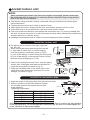
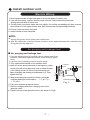
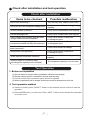
1
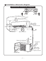
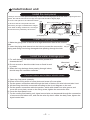
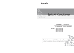
Split Air Conditioner
Air
nditioner
Air
plit
itSplit
ir
onditioner
Conditioner
Air
Split
Conditioner
Conditioner
Conditioner
Air
Split
Conditioner
Air
Split
Conditioner
Air
Split
Conditioner
Air
Split
Conditioner
AirConditioner
AirConditioner
Air
Conditioner
Conditioner
Installation manual
WNER'S
'S
ER'S
OWNER'S
OWNER'S
OWNER'S
MANUAL
OWNER'S
MANUAL
OWNER'S
MANUAL
OWNER'S
MANUAL
MANUAL
MANUAL
OWNER'S
MANUAL
OWNER'S
MANUAL
OWNER'S
MANUAL
OWNER'S
MANUAL
OWNER'S
MANUAL
MANUAL
MANUAL
MANUAL
For air conditioners:
AWI/AWO-21HPR1 Delta
AWI/AWO-25HPR1 Delta
AWI/AWO-32HPR1 Delta
Thank
you
for
choosing
our
air
conditioner,
please
read
this
er
hank
ditioner
osing
IR
AIR
rCAIR
ou
conditioner
ALPICAIR
choosing
for
air
Thank
for
air
you
correct
conditioner
ALPICAIR
air
choosing
for
conditioner
Thank
for
conditioner
you
correct
ALPICAIR
air
choosing
for
operation,
for
Thank
you
conditioner
correct
ALPICAIR
air
choosing
for
operation,
for
conditioner
correct
for
you
ALPICAIR
air
correct
choosing
operation,
please
correct
conditioner
for
for
ALPICAIR
air
operation,
please
choosing
operation,
correct
conditioner
for
operation,
ALPICAIR
air
please
correct
conditioner
for
operation,
air
ALPICAIR
please
correct
please
conditioner
for
operation,
please
air
correct
conditioner
operation,
for
please
air
correct
for
operation,
conditioner
please
correct
for
please
operation,
correct
operation,
please
for correct
operation,
please
please
operation,
pleaseplease
owner's manual carefully before operating the unit and keep
itunit
carefully
for
consultation
arefully
e
efully
ner's
rating
ad
ully
ual
smanual
efore
operating
owner's
read
this
carefully
before
manual
before
operating
the
owner's
before
read
this
carefully
unit
manual
operating
the
owner's
operating
this
before
carefully
read
and
operating
manual
the
owner's
before
carefully
keeps
this
and
operating
unit
manual
the
before
the
owner's
carefully
keeps
and
operating
the
unit
manual
unit
before
unit
carefully
keeps
and
operating
the
and
manual
and
before
carefully
keeps
unit
operating
the
keeps
keeps
before
and
unit
the
carefully
operating
keeps
before
and
unit
operating
thekeeps
and
unit
before
operating
thekeeps
and
unit
the
operating
keeps
and
unit
thekeeps
and
unitthe
keeps
and
unit
keeps
and keeps
or
nsultation.
ully
ation.
carefully
consultation.
itfor
carefully
consultation.
it for
carefully
consultation.
for
it carefully
consultation.
for consultation.
for consultation.
Installation service- Notices for installation
Important Notices
1. The unit installation work must be done by qualified personnel according to the local
rules and this manual.
2. If the air conditioner has not plug, directly connect it into the fixed circuit, a breaker should be
installed in the fixed circuit. all pole of this breaker should be switching off and the distance
of the contact should be at least 3mm.
Basic Requirements For Installation Position
Install in the following place may cause malfunction. If it is unavoidable contact with
service center please:
● Place
where strong heat sources, vapors, flammable gas or volatile objuct are emitted
where high-frequency waves are generated by radio equipment, welders and
medical equipment.
● Place where a lot of salinities such as coast exists.
● Place where the oil (machine oil) is contained in the air.
● Place
●
Place where a sulfured gas such as the hot spring zones is generated.
place with special circumstance.
● Other
Indoor Unit Installation Position Selection
1. The air inlet and outlet vent should be far from the obstruction, make sure that the air
can be blown through the whole room.
2. Select a position where the condensing water can be easily drained out, and the place
is easily connected for outdoor unit.
3. Select a location where the children can not reach.
4. Can select the place where is strong enough to withstand the full weight and vibration of
the unit. And will not increase the noise.
5. Be sure to leave enough space to allow access for routine maintenance. The height of the
installed location should be 230 cm or more from the floor.
6. Select a place about 1m or more away from TVset or any other electric appliances.
7. Select a place where the filter can be easily taken out.
8. Make sure that the indoor unit installation should accord with installation dimension
diagram requirements.
Outdoor Unit Installation Position Selection
1. Select a location from which noise and outflow air emitted by unit will not inconvenience
neighbors, animals, plants.
2. Select a location where there should be sufficient ventilation.
3. Select a location where there should be no obstructions cover the inlet and outlet vent.
4. The location should be able to withstand the full weight and vibration of the outdoor unit
and permit safe installation.
5. Select a dry place, but do not expose under the direct sunlight or strong wind.
6. Make sure that the outdoor unit installation dimension should accord with installation
dimension diagram, convenient for maintenance, repair.
7. The height difference of connecting the tubing within 5m, the length of connecting the
tubing within 10m.
8. Select a place where it is out of reach for the children.
9. Select a place where will not block the passage and do not influence the city appearance.
2
Notices for installation
Safety Requirements For Electric Appliances
1. The power supply should be used the rated voltage and AC exclusive circuit,
the power cable diameter should be satisfied.
2 Don't drag the power cable emphatically.
3
It should be reliably earthed, and it should be connected to the special earth device,
the installation work should be operated by the professional.
The air switch must have the functions of magnetic tripping and heat tripping, in order
to protect the short circuit and overloading.
4. The min. distance from the unit and combustive surface is 1.5m.
Note:
●
Make sure that the Live wire or Zero line as well as the earth wire in the family power
socket can not be wrong connected, there should be reliable and no short circuit in the
diagram.
●
wrong connection may cause fire.
Earthing requirements
1. Air conditioner is type I electric appliance, thus please do conduct reliable earthing
measure.
2. The yellow-green two-color wire in air conditioner is earthing wire and cannot be used
for other propose. It cannot be cut off and be fix it by screw, otherwise it would cause
electric shock.
3. The earth resistance should accord to the National Criterion.
4. The user power must offer the reliable earthing terminal. Please don't connect the
earthing wire with the following place:
① Tap water pipe ② Gas pipe
③ Contamination pipe ④ Other places that professional personnel consider them unreliable.
Others
1.The connection method of unit and power cable as well as the interconnect method
of each isolated component should refer to the circuit diagram stick on the unit.
2.The model of the blown fuse and rated value should refer to the silk-screen on the
controller or fuse sleeve.
3. The appliance shall be installed in accordance with national wiring regulations.
4. This appliance is not intended for use by persons (including children) with reduced
physical, sensory or mental capabilities, or lack of experience and knowledge, unless
they have been given supervision or instruction concerning use of the appliance by a
person responsible for their safety.
5. Children should be supervised to ensure that they do not play with the appliance.
3
Installation dimension diagram
Installation dimension diagram
15
cm
Space to the ceiling
Above
15cm Above
15cm Above
Space to the wall
Space to the wall
300
cm
230
2
cm
Above
Above
Air outlet side
Air inlet side
30
cm
Ab
ov
e
Space to the obstruction
50cm Above
Space to the floor
30cm Above
20
0c
mA
bo
ve
50cm Above
Space to the wall
Air outlet side
4
Install indoor unit
Install the rear panel
1.Always mount the rear panel horizontally. As the water drainage pipe at the left, when adjusting the rear
panel, this side should not be too high; the right side should be slightly high.
2. Fix the rear panel on the selected location Wall
3. Be sure that the rear panel has been
fixed firmly enough to withstand the weight
of an adult of 60kg, furthermore, the weight
should be evenly shared by each screw.
Space to
the wall
150mm
above
Space to
the wall
150mm
above
Left
(Rear piping hole)
Wall
Gradienter
Mark on the middle of it
Fig.1
Right
(Rear piping hole)
Install the piping hole
1. Make the piping hole in the wall at a slight downward slant to the outdoor
Indoor
side.
2. Insert the piping-hole sleeve into the hole to prevent the connection Wall pipe
piping and wiring from being damaged when passing through the hole.
Outdoor
Seal pad
Install the water drainage pipe
1. For well draining, the drain hose should be placed at a
downward slant.
2. Do not wrench or bend the drain hose or flood its end
by water.
3. When the long drainage hose passing through indoor,
should wrap the insulation materials.
Wrenched
Bent
Flooded
Connect indoor and outdoor electric wires
1. Open the front panel upwardly.
2.Screw off the fixing screw of cover plate and screw off cover plate.
3. Put the power connection cable through the back of indoor unit wire hole and take it out.
4. All the wiring should be connected according to the circuit diagram on the unit.
5. Put the power connection cable the section, which with sheath into wire groove, and
cover the cover plate, screw on the fixing screw, tighten the connection wire.
6. Cover the front panel cover.
7. For the cooling and heating unit, signal control wire can be passed through the connection
of connector and indoor unit, and use the wire clip that is under the body case, tighten the
signal control wire.
5
Install indoor unit
NOTE:
When connecting the electric wire if the wire length is not enough, please contact with
the authorized service shop to buy a exclusive electric wire that is long enough and the
joint on the wire are not allowed.
The electric wiring must be correctly connected, wrong connection may cause spare
parts malfunction.
● Tighten the terminal screw in order to prevent loose.
● After tighten the screw, slightly pull the wire and confirm whether is it firm or not.
● If the earth wire is wrong connection, that may cause electric shock.
● The cover plate must be fixed, and tighten the connection wire, if it is poor installed, that
the dust, moisture may enter in or the connection terminal will be affected by outside force,
and will cause fire or elelctric shock.
● Leakage circuit-breaker and air switch of correct capacity must be installed.
●
Install the indoor unit
External connection
Gas side piping electric wire
Liquid side
piping
● The
piping can be lead out from right, right rear,
left, left rear.
When
routing the piping and wiring from the left
1.
or right side of indoor unit, cut off the tailings
from the chassis in necessary (show in Fig.2)
(1).Cut off the tailings 1 when routing the wiring only;
(2).Cut off the tailings 1 and tailings 2 when routing
both the wiring and piping.(or 1,2,3);
2.Take out the piping from body case, wrap the piping
electric wire, water pipe with tape and put them through the piping hole (As show in Fig. 3)
Tailing 3
Tailing 2
Tailing1
Fig.2
Liquid side
Gas side piping
piping
insulation
Finally wrap it
insulation
with tape Water drainage pipe
Fig.3
Left
Right
Right rear
Left rear
Fixing hook
Mounting
board
3.Hang the mounting slots of the indoor unit on the
upper tabs of the rear panel and check if it is firm
enough. (As show in Fig.4)
Mounting
board
Fig.4
Install the connection pipe
1.Align the center of the piping flare with the relevant valve.
2.Screw in the flare nut by hand and then tighten
the nut with spanner and torque wrench refer
to the following.
Tightening torque table
Hex nut diameter
Tightening torque(N·m)
Ф6
Ф 9.52
Ф 12
Ф 16
Ф 19
15~20
31~35
50~55
60~65
70~75
Indoor unit piping
Spanner
Taper nut
Piping
Torque wrench
NOTE: Firstly connect the connection pipe to indoor unit, then to outdoor unit; pay attention
to the piping bending, do not damage the connection pipe; the joint nut couldn't tighten too
much, otherwise it may cause leakage.
6
Install outdoor unit
Electric Wiring
1. Disassemble handle of right side plate or front side plate of outdoor unit.
2. Take off wire clamp, connect and fix power connect cord to terminal of line bank.
Wiring should fit that of indoor unit.
3. Fix the power connection cable with wire clamp, for cooling and heating unit, then use the
wire clamp to fix the signal control wire, then connect the corresponding connector.
4. Ensure if wire has been fixed well.
5. Install handle or front side plate.
NOTE:
●
Wrong wiring may cause spare parts malfunction.
●
After the cable fixed, make sure there should be a free space between the connection and
fixing place on the lead wire.
Air purging and leakage test
● Air purging and leakage test
1. Connect charging hose of manifold valve to charge end of low
pressure valve (both high/low pressure valves must be tightly
shut).
2. Connect joint of charging hose to vacuum pump.
3. Fully open handle handle of Lo manifold valve.
4. Open the vacuum pump to evacuate. At the beginning, slightly
loosen joint nut of low pressure valve to check if there
is air coming inside. (If noise of vacuum pump has
been changed, the reading of multimeter is 0) Then
tighten the nut.
5. Keep evacuating for more than 15mins and make
sure the reading of multi-meter is -1.0 10 5pa
(-76cmHg).
6. Fully open high/low pressure valves.
7. Remove charging hose from charging end of low
pressure valve.
8. Tighten bonnet of low-pressure valve. (As shown in Fig.5)
7
Liquid pipe
Gas pipe
Valve
cap
Vacuum pump
Fig. 5
Vacuum
gauge
Install outdoor unit
● Leak hunting
Indoor unit check point
Use soap water or leak hunting meter to check whether
the joints is leak.
Indoor unit check point
Fig.6
Outdoor condensation drainage (Heat pump type only)
When the unit is heating, the condensing water
and defrosting water can be drained out reliably
through the drain hose.
Installation: Install the outdoor drain elbow in
Ø 25 hole on the base plate, and joint the
drain hose to the elbow, so that the wastewater
formed in the outdoor unit can be drained out
to a proper place.
8
Chasis
Outdoor drain
elbow
Check after installation and test operation
Check after installation
Items to be checked
Possible malfunction
Has it been fixed firmly?
The unit may drop, shake or emit noise.
Have you done the refrigerant leakage test?
It may cause insufficient cooling(heating)
capacity.
Is heat insulation sufficient?
It may cause condensation and dripping.
Is water drainage well?
It may cause condensation and dripping.
Is the voltage in accordance with the rated
voltage marked on the nameplate?
It may cause electric malfunction
or damage the part..
Is the electric wiring and piping
connection installed correctly and securely?
It may cause electric malfunction
or damage the part.
Has the unit been connected to a secure
earth connection?
It may cause electrical leakage.
Is the power cord specified?
It may cause electric malfunction
or damage the part
Is the inlet and outlet been covered?
It may cause insufficient cooling(heating)
capacity.
Has the length of connection pipes
and refrigerant capacity been recorded?
The refrigerant capacity is not accurate.
Test Operation
1. Before test operation
(1) Do not switch on power before installation isfinished completely.
(2) Electric wiring must be connected correctly and securely.
(3) Cut-off valves of the connection pipes should be opened.
(4) All the impurities such as scraps and thrums must be cleared from the unit.
2. Test operation method
(1) Switch on power, press "ON/OFF" button on the wireless remote control to start the
operation.
(2) Press MODE button, to select the COOL, HEAT, FAN to check whether the operation
is normal or not.
9