1
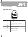
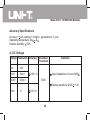
Model UT211: OPERATING MANUAL
Table of Contents
Title
Overview
Unpacking Inspection
Safety Information
Rules For Safe Operation
International Electrical Symbols
The Meter Structure
Functional Buttons
Display Symbols
Measurement Operation
A. DC & AC Voltage Measurement
B. AC Current Measurement
C. Measuring Resistance
D. Frequency and Duty Cycle Measurement
E. Operation of Hold Mode
General Specifications
Accuracy Specifications
A. DC Voltage
1
Page
3
4
5
7
9
10
10
11
13
13
15
16
18
18
20
22
22
Model UT211: OPERATING MANUAL
Title
B. AC Voltage
C. AC Current
D. Resistance
E. Frequency
F. Duty Cycle
Maintenance
A. General Service
B. Replacing the Battery
Page
23
23
24
25
25
26
26
26
2
Model UT211: OPERATING MANUAL
Overview
This Operating Manual covers information on safety and cautions. Please read the
relevant information carefully and observe all the Warnings and Notes strictly.
Warning
To avoid electric shock or personal injury, read the “Safety Information” and “Rules
for Safety Operation” carefully before using the Meter.
The Model UT211 (hereafter referred to as “the Meter”) are a 3999 counts 3 3/4 digits
auto clamp multimeter, they auto sense on AC & DC voltage, AC current and resistance
measurement. They have full range overload protection and special outlook design.
They are such a smart electrical testing clamp meter.
It equips also with frequency, duty cycle, low battery display and data hold features.
3
Model UT211: OPERATING MANUAL
Unpacking Inspection
Open the package case and take out the Meter. Check the following items carefully
to see any missing or damaged part:
Item
1
2
3
Description
Qty
Operating Manual
Test Lead
9V Battery (NEDA 1604, 6F22 or 0006P)
(installed inside the Meter)
1 piece
1 pair
1 piece
In the event you find any missing or damage, please contact your dealer immediately.
4
Model UT211: OPERATING MANUAL
Safety Information
This Meter complies with the standards IEC61010: in pollution degree 2, overvoltage
category (CAT. II 600V / CAT III 300V) and double insulation.
CAT II: Local level, appliance, PORTABLE EQUIPMENT etc., with smaller transient
voltage overvoltages than CAT. III
CAT. III: Distribution level, fixed installation, with smaller transient overvoltages than
CAT. IV.
Under the influence of Radiated, Radio-Frequency Electromagnetic Field phenomenon,
the UT211 may malfunction and can self-recover after the test.
Use the Meter only as specified in this operating manual, otherwise the protection
provided by the Meter may be impaired.
In this manual, a Warning identifies conditions and actions that pose hazards to the
user, or may damage the Meter or the equipment under test.
5
Model UT211: OPERATING MANUAL
A Note identifies the information that user should pay attention on.
International electrical symbols used on the Meter and in this Operating Manual are
explained on page 9.
6
Model UT211: OPERATING MANUAL
Rules For Safe Operation
Warning
To avoid possible electric shock or personal injury, and to avoid possible
damage to the Meter or to the equipment under test, adhere to the following
rules:
Check for the lever is in good condition when measuring AC current.
Must center the wire (conductor) within the transformer jaw.
Before using the Meter inspect the case. Do not use the Meter if it is damaged
or the case (or part of the case) is removed. Look for cracks or missing
plastic. Pay attention to the insulation around the connectors.
Inspect the test leads for damaged insulation or exposed metal. Check the
test leads for continuity. Replace damaged test leads with identical model
number or electrical specifications before using the Meter.
Do not apply more than the rated voltage 600V, between the terminals or
between any terminal and grounding.
When the Meter working at an effective voltage over 60V in DC or 30V in AC,
special care should be taken for there is danger of electric shock.
When using the test leads, keep your fingers behind the finger guards.
7
Model UT211: OPERATING MANUAL
Disconnect circuit power and discharge all high-voltage capacitors before
testing resistance.
Replace the battery as soon as the battery indicator appears or no display
when turning on the Meter. With a low battery, the Meter might produce
false readings that can lead to electric shock and personal injury.
Before carrying out any measurement, make sure the Meter is in good
condition after turning it on.
When servicing the Meter, use only the same model number or identical
electrical specifications replacement parts.
The internal circuit of the Meter shall not be altered at will to avoid damage
of the Meter and any accident.
Soft cloth and mild detergent should be used to clean the surface of the
Meter when servicing. No abrasive and solvent should be used to prevent
the surface of the Meter from corrosion, damage and accident.
Turn the Meter off when it is not in use and take out the battery when not
using for a long time.
Constantly check the battery as it may leak when it has been using for some
time, replace the battery as soon as leaking appears. A leaking battery will
damage the Meter.
8
Model UT211: OPERATING MANUAL
Do not use or store the Meter in an environment of high temperature, humidity,
explosive, inflammable and strong magnetic field. The performance of the
Meter may deteriorate after dampened.
International Electrical Symbols
Deficiency of Built-In Battery
AC or DC
Grounding
The allowed removable dangerous voltages existed between the leads.
Conforms to Standards of European Union
Warning. Refer to the Operating Manual
Double Insulated
9
Model UT211: OPERATING MANUAL
The Meter Structure (see figure 1)
1. Transformer Jaws designed to pick up the AC
current flowing through the conductor.
2. LCD Display.
3. Function Buttons
4. Input Terminals
1
2
3
4
Functional Buttons
Below table indicated for information about the functional
button operations.
(figure 1)
Button
Operation Performed
Hz/%
Press to select Frequency or Duty Cycle measurement mode.
HOLD
Press HOLD to enter the Hold mode in any mode
Press to turn the Meter on and off.
(POWER)
10
Model UT211: OPERATING MANUAL
Display Symbols (see figure 2)
(figure 2)
Number
Symbol
Meaning
1
Hz / %
Frequency and duty cycle measurement
2
HOLD
Data hold is active.
3
“
Indicator for negative reading
4
AC
Indicator for AC Voltage.
5
DC
Indicator for DC Voltage
“
11
Model UT211: OPERATING MANUAL
Number
Symbol
Meaning
6
OL
Indicator for overloading
7
Auto
The Meter is in the auto range mode in which the
Meter automatically selects the range with the best
resolution.
The battery is low.
Warning: To avoid false readings, which could lead
to possible electric shock or personal injury, replace
the battery as soon as the battery indicator appears.
8
9
,k ,M
Ohm. The unit of resistance.
Kilohm. 1 x 10³ or 1000 ohms.
Mega ohm. 1 x 10⁶ or 1,000,000 ohms.
V
Volts. The unit of voltage.
A
Indicator for AC current
Hz
Hertz. The unit of frequency.
%
Percent: Used for duty cycle measurements.
12
Model UT211: OPERATING MANUAL
Measurement Operation
The LCD displays full icon while turning on the Meter, then the Meter will enter to
resistance testing mode, the LCD display “OL”.
A. DC and AC Voltage Measurement (See figure 3)
Warning
To avoid harms to you or damages to the Meter
from electric shock, please do not attempt to
measure voltages higher than 600V although
readings may be obtained.
red
When measure high voltages, take extra care
to avoid electric shock.
figure 3
13
black
Model UT211: OPERATING MANUAL
To measure DC and AC voltage, connect the Meter as follows:
1. Insert the red test lead into the V terminal and the black test lead into the COM
terminal.
2.Connect the test leads across with the object being measured. When the AC
voltage is higher than AC1.4V or DC voltage is higher than ±1.4V, the Meter will
automatically enter the voltages measurement mode.
The measured value shows on the display.
Note
Input Impedance is around 10M .
When DC and AC voltage measurement has been completed, disconnect the
connection between the testing leads and the circuit under test, and remove the
testing leads away from the input terminals of the Meter.
14
Model UT211: OPERATING MANUAL
B. AC Current Measurement (See figure 4)
To measure current, do the following:
1.Check the lever is in good condition.
2. Press the lever to open the transformer jaws.
3. Center the conductor within the transformer jaw
like figure 5
4. When the tested current is greater than AC0.4A,
the Meter will automatically enter current testing
mode.
The measured value shows on the display, it is a
effective value of sine wave (mean value response).
correct
incorrect
N
a
Note
b
figure 4
When current measurement has been
completed, disconnect the connection between
the conductor under test and the jaw, and
remove the conductor away from the
transformer jaw of the Meter.
15
L
Model UT211: OPERATING MANUAL
C. Measuring Resistance (see figure 5)
Warning
To avoid damages to the Meter or to the devices
under test, disconnect circuit power and discharge
all the high-voltage capacitors before measuring
resistance.
red
When the Meter working at an effective voltage
over 60V in DC or 30V in AC, special care should
be taken for there is danger of electric shock.
figure 5
To measure resistance, connect the Meter as
follows:
1. Insert the red test lead into the terminal and
the black test lead into the COM terminal.
2. Connect the test leads across with the object
being measured.
The measured value shows on the display.
16
black
Model UT211: OPERATING MANUAL
Note
The test leads can add 0.1 to 0.2 of error to resistance measurement. To obtain
precision readings in low-resistance measurement, it is necessary to subtract the
value measured when the testing leads are short circuited from the reading.
If reading with shorted test leads is not less than 0.5 , check for loose test leads,
incorrect function selection, or any other reasons.
The LCD displays OL indicating open-circuit or the tested resistor or the resistor
value is higher than the maximum range of the Meter.
For high-resistance measurement (>1M ), it is normal to take several seconds
to obtain a stable reading.. In order to obtain stable reading, try to use as short
as test lead possible.
When resistance measurement has been completed, disconnect the connection
between the testing leads and the circuit under test, and remove the testing leads
away from the input terminals of the Meter.
17
Model UT211: OPERATING MANUAL
D. Frequency and Duty Cycle Measurement
Frequency Measurement
Press Hz% one time when measuring AC voltage, the LCD display will switch to
frequency measurement mode from voltage measurement mode.
Duty Cycle Measurement
Press Hz% two times when measuring AC voltage or square wave voltage, the LCD
display will switch to duty cycle measurement mode from voltage measurement mode.
E. Operation of Hold Mode
During current measurement
Press HOLD when the Meter is under current measurement mode, the measured
data will be hold. When the measuring signal is removed, the hold data remains
unchanged. Press HOLD again, the hold data will be disappeared and the Meter
automatically enters the resistance measurement mode.
18
Model UT211: OPERATING MANUAL
During voltage, frequency and duty cycle measurement
Press HOLD when the Meter is under voltage, frequency and duty cycle measurement
mode, the measured data will be hold. When the measuring signal is removed, the
hold data will be disappeared. The Meter automatically enters resistance measurement
mode.
Resistance measurement
Press HOLD when the Meter is under resistance measurement mode, the measured
data will be hold. When the measuring signal is removed, the hold data remains
unchanged. Press HOLD again, the hold data will be disappeared.
19
Model UT211: OPERATING MANUAL
General Specifications
Maximum Voltage between
any Terminals and Grounding:
Maximum Current Measurement:
of Transformer Jaw:
Auto Function:
Maximum Display:
Overload Display:
Range:
Polarity Display:
Measurement Speed:
Below 1V/m electrostatic discharge:
Over 1V/m electrostatic discharge:
Temperature:
Relative Humidity:
Refer to different range input protection
voltage.
400A.
Auto detect
Digital: 3999, 3 3/4 digits
OL
Auto
Auto
Updates 2-3 times/second.
Accuracy = specified accuracy + 5% of the
range.
Without specified accuracy.
Operating: 0 to +40 (32 to +104 ).
Storage: -10 to +50 (14 to +122 ).
5% @ 0 to 30 ; 50% @ 30 to 40 .
20
Model UT211: OPERATING MANUAL
Altitude:
Battery Type:
Battery Deficiency:
Dimensions (HxWxL):
Weight:
Safety/Compliances:
Operating: 2000 m.
Storage: 10000 m.
One piece of 9V (NEDA1604 or 6F22 or 006P).
Display
210mm x 75.6mm x 30mm
Approximate 300g (battery included).
IEC61010 CAT. II 600V / CAT III 300V overvoltage
and double insulation standard.
Certifications:
21
Model UT211: OPERATING MANUAL
Accuracy Specifications
Accuracy: (a% reading + b digits) , guarantee for 1 year.
Operating temperature: 23
5 .
Relative humidity: 75%.
A. DC Voltage
Range Resolution Accuracy Overload
Protection
4V
1mV
40V
10mV
400V
100mV
(0.8%+1)
Remarks
Input impedance: Around 10M
600V
Testing sensitivity:
60V
1V
(1%+3)
22
DC
1.4V
Model UT211: OPERATING MANUAL
B. AC Voltage
Range Resolution Accuracy Overload
Protection
4V
1mV
40V
10mV
400V
100mV
600V
1V
(1.2%+5)
600V
(1.5%+5)
Remarks
Input impedance: Around 10M
Displays effective value of sine
wave (mean value response).
Frequency response:
50Hz~400Hz.
Testing sensitivity: AC1.4V
C. AC Current
Range Resolution
40A
10mA
400A
100mA
Accuracy
Remarks
0.4A input current
20A: (3.0%+8)
>20A:
(2.0%+8)
200A:
(1.5%+5)
>200A:
(1.5%+50)
23
Frequency response
50Hz~60Hz.
Display effective value of sine
wave (mean value response).
Testing sensitivity: AC0.4A
Model UT211: OPERATING MANUAL
D. Resistance
Range Resolution
Accuracy
Overload Protection
400
0.1
4k
1
40k
10
400k
100
4M
1k
(1.2%+2)
40M
10k
(1.5%+2)
(1.2%+2) + test lead short
circuit resistance value
(1.0%+2)
24
600Vp
Model UT211: OPERATING MANUAL
E. Frequency
Range
Resolution
1kHz
1Hz
Accuracy
(1%+3)
Overload Protection
600Vp
F. Duty Cycle
Range
Resolution
Accuracy
Overload Protection
99.9%
0.1%
For reference only
600Vp
25
Model UT211: OPERATING MANUAL
Maintenance
This section provides basic maintenance information including battery replacement
instruction.
Warning
Do not attempt to repair or service your Meter unless you are qualified to do
so and have the relevant calibration, performance test, and service information.
To avoid electrical shock or damage to the Meter, do not get water inside the case.
A. General Service
Periodically wipe the case with a damp cloth and mild detergent. Do not use
abrasives or solvents.
To clean the terminals with cotton bar with detergent, as dirt or moisture in the
terminals can affect readings.
Turn the Meter off when it is not in use.
Take out the battery when it is not using for a long time.
Do not use or store the Meter in a place of humidity, high temperature, explosive,
inflammable and strong magnetic field.
26
Model UT211: OPERATING MANUAL
B. Replacing the Battery (See figure 6)
Warning
To avoid false readings, which could
lead to possible electric shock or
personal injury, replace the battery as
soon as the battery indicator “
”
appears or no display when turning on
the Meter.
serew
battery
Make sure the transformer jaw
and the test leads are disconnected
from the circuit being tested before
opening the case bottom.
figure 6
Make sure the test leads are
removed from the input terminals.
27
Model UT211: OPERATING MANUAL
To replace the battery:
1. Turn the meter power off and remove all the connections from the terminals.
2. Remove the screw from the battery compartment, and separate the battery compartment
from the case bottom.
3. Remove the battery from the battery compartment.
4. Replace the battery with a new 9V battery (NEDA1604, 6F22 or 006P).
Rejoin the case bottom and battery compartment, and reinstall the screw.
** END **
This operating manual is subject to change without notice.
28
Model UT211: OPERATING MANUAL
29
Model UT211: OPERATING MANUAL
Copyright 2005 Uni-Trend Group Limited.
All rights reserved.
Manufacturer:
Uni-Trend Technology (Dongguan) Limited
Dong Fang Da Dao
Bei Shan Dong Fang Industrial Development District
Hu Men Town, Dongguan City
Guang Dong Province
China
Postal Code: 523 925
Headquarters:
Uni-Trend Group Limited
Rm901, 9/F, Nanyang Plaza
57 Hung To Road
Kwun Tong
Kowloon, Hong Kong
Tel: (852) 2950 9168
Fax: (852) 2950 9303
Email: [email protected]
http://www.uni-trend.com
30