1
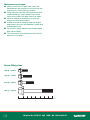
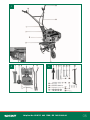
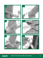
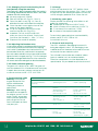
163cc
Petrol Tiller
Original Operating
Instructions
DEPTH STOP
THROTTLE CONTROL
36CM WORKING WIDTH/
23CM WORKING DEPTH
TILTABLE GUIDANCE
WHEELS
4 TILLER BLADES
penetrate the soil
automatically and smoothly
AFTER SALES SUPPORT
UK / IRELAND HELPLINE NO 0151 6491500
REP. IRELAND HELPLINE NO 1890 946244
WEB SUPPORT
www.einhell-uk.co.uk
MODEL NUMBER: HQ-MT 3336
HOMEBASE ARTICLE NUMBER: 318775
Contents
03. Safety guide
05. Assembly and Parts list
11. Getting Started
13. Operation
14. Trouble Shooting
16. Declaration of Conformity
17. Guarantee Certificate
02
Helpline No. UK 0151 649 1500 / IRE 189 094 6244
1. Safety Information
General notes:
n Read the operating instructions carefully.
Familiarize yourself with the operator controls
and proper operation of the machine.
n Never allow children or other persons who are
not familiar with the operating instructions to use
the machine.
n Never work in the direct vicinity of persons especially children or animals.
n Always keep in mind that the machine operator
or user is responsible for accidents involving other
persons and/or their property.
Preparations:
n Always wear sturdy, non-slip footwear and long
trousers when using the machine. Never use the
machine barefoot or in sandals.
n Thoroughly check the grounds on which the
machine will be used and remove all objects
that could be caught up by the machine and
violently flung out.
n Warning! Petrol is highly flammable! Therefore:
n Only store petrol in containers designed to hold
petroleum-based liquids.
n Only refuel out in the open and do not smoke
during the refuelling process.
n Always refuel before starting the engine. Do not
open fuel tank cap and do not refuel when the
engine is running or when the engine is hot.
n If petrol has overflowed, do not under any
circumstances attempt to start the engine.
Instead, remove the machine from the affected
area. Avoid starting the engine until the petrol
fumes have completely evaporated.
n For safety reasons, the petrol tank and other tank
closures must be replaced at regular intervals.
n Replace damaged exhaust silencers.
n Before using the machine, always visually
examine the tools for excessive wear or
damage. To prevent any imbalance, replace
worn out or damaged parts and fastening bolts
as a set only.
Handling
n Do not let the engine run in enclosed areas, as
dangerous carbon monoxide gas can build up.
n Only use the machine in broad daylight or in
well-lit conditions.
n Always maintain good footing on inclines.
n Only operate the machine at a walking pace.
n For machines with wheels: Always guide the
machine across slopes, i.e. never straight up or
straight down.
n Be particularly careful when you change
direction on a slope.
n Be particularly careful when you turn the
machine around or pull it toward yourself.
n Do not adjust or overclock the engine speed
settings.
n Start the engine carefully in accordance with the
manufacturer’s instructions and ensure that your
feet are far enough away from the tool(s).
n Never move your hands or feet toward or under
any rotating parts.
n Never lift or carry a machine with the engine
running.
n Always stop the engine.
- Whenever you leave the machine;
- Before refuelling;
- Close the engine’s throttle valve
when the engine runs down.
n When you have finished working with the
machine, close the petrol stopcock if it has one.
n For safety reasons the engine speed is not
permitted to exceed the speed shown on the
motor rating plate.
n Start the engine carefully in accordance with the
operating instructions. Never attempt to touch
any moving parts while the engine is running.
Helpline No. UK 0151 649 1500 / IRE 189 094 6244
03
Maintenance and storage:
n Make sure that all nuts, bolts and screws are
tightened securely at all times to ensure that the
machine is in a safe working condition.
n Never store the machine (with petrol in the tank)
inside a building in which petrol fumes could
come into contact with open flames or sparks.
n Allow the engine to cool before you put the
machine in an enclosed area.
n In order to avoid fire hazards, keep the engine
and exhaust free from all vegetation matter and
leaking grease (oil).
n For your own safety, replace worn or damaged
parts without delay;
n If the tank needs to be emptied, ensure that it is
done out in the open.
Screw fitting sizes
14(x 4) = 20mm
13(x 4) = 30mm
21(x 5) = 35mm
19(x 1) = 80mm
0mm 10mm 20mm 30mm 40mm 50mm 60mm 70mm 80mm
04
Helpline No. UK 0151 649 1500 / IRE 189 094 6244
1
2
3
Helpline No. UK 0151 649 1500 / IRE 189 094 6244
05
06
4
5
6
7
8
9
Helpline No. UK 0151 649 1500 / IRE 189 094 6244
10
11
12
13
14
15
Helpline No. UK 0151 649 1500 / IRE 189 094 6244
07
16
17
18
18a
8
2
1
27
8
18b
27
19
08
19a
Helpline No. UK 0151 649 1500 / IRE 189 094 6244
20
21
22
23
24
25
Helpline No. UK 0151 649 1500 / IRE 189 094 6244
09
26
10
Helpline No. UK 0151 649 1500 / IRE 189 094 6244
Important!
When using the equipment, a few safety
precautions must be observed to avoid
injuries and damage. Please read the
complete operating manual with due care.
Keep this manual in a safe place, so that
the information is available at all times. If you
give the equipment to any other person, give
them these operating instructions as well.
We accept no liability for damage
or accidents which arise due to nonobservance of these instructions and the
safety information.
1.Safety information
CAUTION!
Read all safety regulations and
instructions.
Any errors made in following the safety
regulations and instructions may result in an
electric shock, fire and/or serious injury.
Keep all safety regulations and
instructions in a safe place for future use.
Explanation of the symbols on the machine
(Fig. 26):
1 Important! Read the operating instructions.
Follow the warnings and safety instructions.
2 Important! Risk of injury from rotating parts.
Keep your hands, feet and clothing away from these parts.
3 Always make sure that the machine is standing solidly whenever you leave it.
4 Important! Hot machine parts. Keep your distance.
5 Important! Switch off the engine before refueling.
6 Description of the clutch lever: 0 = tiller blade
”Stop”; 1 = tiller blade “On/Run”
2.Layout (Fig. 1-3)
1 Holder for steering handle
2 Transport wheel with holder
3 Engine / gear unit
4 Depth stop
5 Steering handle – throttle lever
6 Steering handle – clutch handle
7 Hand pull starter
8 Clutch handle
9 Bar for spark plug wrench
10Spark plug wrench
11Safety split pin for depth stop
12Resetting spring for transport wheel
13Four screws size M6 x 30mm for fastening
the steering handle
14Four screws size M6 x 20mm for the
steering handle holder
158 x nuts size M6
16Four M6 washers
17Four M6 spring washers
18Four large M6 washers
19Screw size M8 x 80mm
20Nut size M8
215 x Screw size M6 x 35mm
22Domed nut size M6
23Safety split pin for resetting spring
24Open-ended spanner size 10/12
25Open-ended spanner size 13/15
26 Cross strut
27 Clutch Handle Lock
3.Proper use
The machine is designed for digging over beds
and fields. Be sure to observe the restrictions
in the safety instructions (Section.1. Page 3).
The machine is to be used only for its
prescribed purpose. Any other use is deemed
to be a case of misuse. The user / operator
and not the manufacturer will be liable for
any damage or injuries of any kind caused
as a result of this.
Please note that our equipment has not been
designed for use in commercial, trade or
industrial applications. Our warranty will be voided
if the machine is used in commercial, trade or
industrial businesses or for equivalent purposes.
Helpline No. UK 0151 649 1500 / IRE 189 094 6244
11
4.Technical data
Engine:
4-stroke engine, 163 ccm
Engine rating:
3.3 kW / 4.5 hp
Engine working speed:
3600 rpm
Working width:
36 cm
Tiller blade diameter:
26 cm
Forward gear:
Starting system:
Fuel:
Engine oil:
Tank capacity:
Vibration ahv:
1
Hand pull starter
Regular unleaded petrol
approx. 0.6 l (10W30)
approx. 2.2 l
6.1 m/s2
Weight:
34 kg
Spark plug:
F7 TC
5.Before starting the equipment
1.Place the engine/gear unit (3) on its left side
(air filter / carburettor) and then assemble the
petrol tiller as follows. (Use the spanners 24 &
25 to tighten / loosen the screws and nuts).
2. Insert the transport wheel holder in the mount on the drive unit (see Fig. 4).
3. Fasten the transport wheel holder with the help of the screw (19) and the nut (20) (see Fig. 5 and 6).
4.Tension the resetting spring between
the engine unit and the transport wheel
holder (2). To do so, first hang the hook of
the spring (12) in the hole on the inside
of the gear (3) unit in the hole provided.
Then fit the eyelet on the spring onto the
bolt notches on the transport wheel (2).
Now insert the safety split pin (23) in the
bolt hole provided on the transport wheel
to secure the spring and ensure that it
cannot slip off (Fig. 7-8).
5.Insert the depth stop (4) in the opening
at the back of the gear unit (3) and
fasten it with the safety split pin (11) at the
working height you require (3 positions are
available; when using for the first time we
would recommend the middle position)
(Fig. 9-10).
12
6.Stand the petrol tiller upright and feed the
Bowden wire for the clutch through the lower
opening in the holder for the steering handles (Fig.11).
7.Fit the holder for the steering handles (1)
to the engine unit (3) and fasten with the
screws (14), the spring washer (17) and
the washers (16) as shown in Fig.12-14.
8.Then fit the steering handles through the
openings on the holder for the steering
handles (6) on the left hand side and (5)
on the right hand side and fasten with the
screws (13), large M6 washers (18) and
nuts (15) as shown in Fig. 15-16.
9.Feed the clutch cable through the holder
for the steering handles and fasten the
Bowden wire adjuster to the eyelet provided
on the steering handle by unscrewing the
upper lock nut and inserting the thread on
the adjuster through the eyelet. Then attach
the Bowden wire to the clutch lever (see fig.17).
10. Fit the clutch lever to the left-hand steering handle and fasten the clutch lever to the steering handle with the screw (21) and the domed nut (22)
(see Fig.18 / Fig.18b).
11. Adjust the cable to the right length with
the help of the adjuster (see Fig. 17/A) as
follows: When the clutch lever is pressed
there must be sufficient tension in the
V-belt for the star-type tiller blades to turn,
whereas when the clutch lever is released
the star-type tiller blades must not move.
Then tighten the two nuts against each other.
Ensure that the Clutch Handle Lock
functions correctly, before starting the
engine. You should not be able to
operate the clutch Handle, until the
Clutch Handle Lock is in the correct
position. (Fig 18a = stopped. Fig. 18b =
Blades will rotate).
12.To fit the throttle lever, first unscrew the screws on the throttle lever. Then attach the throttle lever to the right-hand steering handle (5) (Fig.19).
13.Fit the cross strut (26) using the screws (21)
and nuts (15) as shown in Figure 19a.
Important! You must fill up with engine oil
and fuel before you can start the engine.
Helpline No. UK 0151 649 1500 / IRE 189 094 6244
n
n
n
Check the fuel and engine oil levels and refill or top up if required.
Make sure that the ignition cable is secured to the spark plug.
Check the area immediately around the petrol tiller.
6.Operation
n
n
n
n
n
n
n
n
n
n
Set the depth stop (4) to the desired depth and secure with the split pin.
Swing the transport wheel up and make sure that the bolt is engaged in the notch in the mount at the front.
Push the petrol fuel tap (Fig. 1/Item A) to
the “ON” position. (Push the lever towards
the engine).
Push the starter lever down to the “Choke”
position (Fig. 19/Item A).
Pull the start cable (7) gently until you
feel resistance, then pull vigorously. If the
engine does not start up immediately,
repeat the above steps.
Move the starter lever to the position in the
middle (Fig. 19/Item B) = working position
).
(Engine speed: fast( )/slow(
S tarter lever position (Fig.19/Item C) =
stop engine (‘0’).
Depending on how tall you are you can
adjust the complete holder for the steering
handles to the top position. To do so,
loosen the screws (Fig. 14/Item A), adjust
the bracket and retighten the screws.
To start the star-type tiller blades, rotate
the clutch handle lock (27) counterclockwise and press the clutch handle (8) down and hold in this position (See Fig. 18 / Fig. 18b). Releasing the clutch handle brings the star type tiller blades to a stop (if they do not stop, readjust the clutch cable).
If the engine is to be stopped for some
time, then pull the fuel tap lever to the
‘OFF’ position (Lever pointing away from
the engine). (Fig. 1/Item A).
7.Cleaning, maintenance, storage and ordering of spare parts
Pull off the spark plug boot (fig.23) before doing
any cleaning and maintenance work. Also pull
the fuel tap lever to the ‘OFF’ position (Lever
pointing away from the engine). (Fig.1/Item A).
7.1 Cleaning
n Keep all safety devices, air vents and the
motor housing free of dirt and dust as much
as possible. Wipe the equipment with a clean
cloth or blow it with compressed air at low
pressure..
n We recommend that you clean the device immediately each time you have finished using it.
n Clean the equipment regularly with a moist cloth and some soft soap. Do not use cleaning agents or solvents; these could attack the plastic parts of the equipment. Ensure that no water can seep into the device.
7.2 Maintenance
Please note: Switch off the unit immediately
and contact the UK helpline 0151 649 1500
n In the event of unusual vibrations or noise.
n If the engine appears to be overloaded or misfires.
7.2.1 Air filter maintenance
n Check and clean the air filter before every use, and replace it if necessary.
n Undo the screw on the air filter cover (Fig. 20) and remove the cover (Fig. 21).
n Remove the filter element (Fig. 22).
n Do not use abrasive cleaning agents or petrol to clean the element.
n Clean the element by tapping it on a flat surface.
n Assemble in reverse order.
7.2.2 Spark plug maintenance
Check the spark plug for dirt and grime
after 10 hours of operation and if necessary
clean it with a copper wire brush. Thereafter
service the spark plug after every 50 hours
of operation.
n Pull off the spark plug boot (Fig. 23) with a twist.
n Remove the spark plug (Fig. 23/Item A with
the supplied spark plug wrench and bar.
n Assemble in reverse order.
Helpline No. UK 0151 649 1500 / IRE 189 094 6244
13
7.2.3 Changing the oil and checking the oil
level (before using the machine)
The motor oil is best changed when the motor is
at working temperature and the tiller is on a flat
surface with the motor level.
n Use only engine oil (10W30).
n Take out the dip stick (Fig. 24 / Item A).
n Open the drain screw (Fig. 24 / Item B) and allow the warm oil to drain into a drip tray.
n Close the drain screw again when all the waste oil has been drained.
n Fill up with engine oil as far as the top mark on the dip stick (Fig. 25/H).
n Important: Do not screw the dip stick when you check the oil level, simply insert it as far as the thread (H = Max. / L= Min.).
n Dispose of the waste oil properly.
7.3 Storage
Pull the fuel tap lever to the `OFF’ position (Lever
pointing away from the engine). (Fig. 1/Item A) and
empty the fuel tank before you decommission the
unit for a lengthy period of time. Clean the unit.
7.2.4 Adjusting the Bowden wires
In the working setting it should be possible to push the
clutch lever up to the push bar without this requiring
much effort. If the Bowden wire is too taut for this, it must
be extended. To do this, undo the lock nut opposite
the main cable, extend the screw connector and then
tighten the lock nut again (see Fig. 17/A). If the star-type
tiller blades no longer rotate then the screw connector
will have to be shortened again (as described above).
8. Disposal and recycling
The unit is supplied in packaging to prevent its
being damaged in transit. This packaging is raw
material and can therefore be reused or can be
returned to the raw material system.
7.4 Ordering spare parts
Please provide the following information on all
orders for spare parts:
n Model/type of machine (HQ-MT 3336)
n Article number of the machine (34.302.79)
n ID number of the machine (11020)
n Number of the required spare part
For our latest spare part prices and availability
please call 0151 649 1500 or visit
www.einhell-uk.co.uk.
The unit and its accessories are made of various
types of material, such as metal and plastic.
Defective components must be disposed of as
special waste. Ask your dealer or your local council.
7.2.5 Power cultivator gearing
The gear unit is driven by a V-belt. The gear unit
can be repaired if this should become necessary.
If repairs are necessary, please contact our UK
customer service centre - 0151 649 1500.
9. Troubleshooting guide
Warning: Switch off the
engine and pull off the
ignition cable before
making any checks or
adjustments.
Warning: If, after making
an adjustment or repair to
the engine, you let it run for
a few minutes, remember
that the exhaust and other
parts will get hot. Do not
touch these parts as these
may burn you.
FAULT
POSSIBLE CAUSES
The unit does not operate
smoothly and vibrates
intensively
- Bolts loose
- Spark plug defective
- Check bolts
- Replace spark plug
The engine does not start
-
-
-
-
Throttle lever in wrong position
Spark plug defective
Fuel tank empty
Petrol fuel tap closed
- Check setting
Engine does not run
smoothly
-
-
-
Air filter dirty
Spark plug soiled or defective
lack of engine oil
- Clean the air filter
- Clean or replace the spark plug
Drive power falls
- Clutch play too large
- V-belt loose
- Adjust clutch cable
- Contact customer service
(0151 649 1500)
The engine will not start or dies
after a short period of time
- Spark plug foul
-Clean or replace spark plug
(electrode spacing 0.6 mm)
- Top up fuel
-Turn Fuel Tap ‘ON’
(pull away from engine)
- No fuel
- Fuel Tap ‘OFF’
14
REMEDY
- Replace spark plug
- Top up fuel
- Open petrol fuel tap
Helpline No. UK 0151 649 1500 / IRE 189 094 6244
Please adhere to the following maintenance periods in order to ensure a failure-free operation.
Important! Fill in engine oil and fuel before starting up the engine for the first time.
(4-STROKE)
Before
each use
Check the
engine oil
X
After an
operating
period of 20
hours
After an
operating
period of 50
hours
After an
operating
period of 100
hours
After an
operating
period of 300
hours
for the first time
Change the
engine oil
then every 100
X
hours
Change the
Check the
air filter
filter element if
X
Clean the
air filter
necessary
X
Clean the
petrol filter
Visual inspection
of the unit
Clean the
spark plug
X
X
Distance:
0.6mm,
Replace if
necessary
Check and
readjust the
carburetor's
throttle valve
X*
Clean the
cylinder head
X*
Set the valve
clearance
X*
Important: The positions marked with "X*" should only be carried out by a repair agent.
Helpline No. UK 0151 649 1500 / IRE 189 094 6244
15