1
MESA
TM
HEATING PRODUCTS
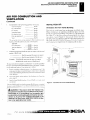
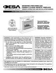
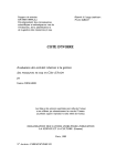
UNVENTED (VENT-FREE) GAS
COMPACT CLASSIC HEARTH®
FIREPLACE
OWNER'S OPERATION AND INSTALLATION MANUAL
For more information, visit
Thermostat Models:
VMH1OTPB, VMH1OTNB,
EFS1OTP and EFS1OTN
Remote-Ready Models:
VMH26PRA, VMH26NRA,
EFS26PR, and EFS26NR
Shown with Optional
Cabinet Mantel/Hearth
Base Accessory
WARNING: If the information in this manual is not
followed exactly, a fire or explosion may result causing property damage, personal injury, or loss of life.
— Do not store or use gasoline or other flammable
vapors and liquids in the vicinity of this or any
other appliance.
— WHAT TO DO IF YOU SMELL GAS
• Do not try to light any appliance.
• Do not touch any electrical switch; do not use any
phone in your building.
• Immediately call your gas supplier from a
neighbor's phone. Follow the gas supplier's instructions.
• If you cannot reach your gas supplier, call the fire
department.
— Installation and service must be performed by a qualified installer, service agency, or the gas supplier.
WARNING: Improper installation,
adjustment, alteration, service, or
maintenance can cause injury or
property damage. Refer to this
manual for correct installation and
operational procedures. For assistance or additional information consult a qualified installer, service
agency, or the gas supplier.
WARNING: This is an unvented gasfired heater. It uses air (oxygen)
from the room in which it is installed. Provisions for adequate
combustion and ventilation air
must be provided. Refer to Air for
Combustion and Ventilation section on page 6 of this manual.
This appliance may be installed in an aftermarket,* permanently located, manufactured
(mobile) home, where not prohibited by local codes.
This appliance is only for use with the type of gas indicated on the rating plate. This appliance
is not convertible for use with other gases.
Aftermarket: Completion of sale, not for purpose of resale, from the manufacturer
.jk
-
iivaI for future reference.
aliEsft
TABLE OF CONTENTS
SAFETY INFORMATION
TABLE OF CONTENTS
SAFETY INFORMATION
2
CLEANING AND MAINTENANCE
29
PRODUCT IDENTIFICATION
3
WIRING DIAGRAM
29
OPTIONAL REMOTE CONTROL ACCESSORIES
4
TROUBLESHOOTING
30
LOCAL CODES
4
SPECIFICATIONS
33
PRODUCT FEATURES
4
REPLACEMENT PARTS
33
UNPACKING
4
SERVICR HINTS
33
ASSEMBLY
5
TEC. -0-IICAL SERVICE
33
AIR FOR COMBUSTION AND VENTILATION
6
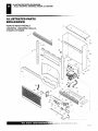
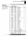
ILLUS :RATED PARTS BREAKDOWN AND PARTS LIST
34
INSTALLATION
8
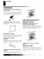
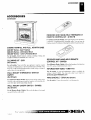
ACCESSORIES
38
OPERATING FIREPLACE
23
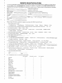
OWNER'S REGISTRATION FORM
INSPECTING BURNERS
28
WARRANTY INFORMATION
41
Back Cover
SAFETY INFORMATION
A WARNINGS
A WARNING: This product contains and/or generates
chemicals known to the State of California to cause
cancer or birth defects, or other reproductive harm.
A
WARNING: Do not use a blower insert, heat
exchanger insert, or other accessory not approved
for use with this fireplace.
A
WARNING: Do not allow fans to blow directly into
IMPORTANT: Read this owner's manual carefully and
the fireplace. Avoid any drafts that alter burner flame
completely before trying to assemble, operate, or service this fireplace. Improper use of this fireplace can patterns. Ceilihs fans can create drafts that alter
burner flame patterns. Altered burner patterns can
cause serious injury or death from burns, fire, explocause sooting.
sion, electrical shock, and carbon monoxide poisoning.
A DANGER: Carbon monoxide poisoning may lead
to death!
Carbon Monoxide Poisoning: Early signs of carbon monoxide
poisoning resemble the flu, with headaches, dizziness. or nausea.
If you have these signs, the fireplace may not he working properly.
Get fresh air at once! Have fireplace serviced. Some people are
more affected by carbon monoxide than others. These include
pregnant women, people with heart or lung disease OF after
those under the influence of alcohol and those at high altitudes.
Natural and Propane/LP Gas: Natural and propanc/LT gases are
odorless. An odor-making agent is added to the gas. The odor
helps you detect a gas leak. However, the odor added to the gas can
fade. Gas may be present even though no odor exists.
Make certain you read and understand all warnings. Keep this
manual for reference. It is your guide to safe and proper operation
of this fireplace.
—
A WARNING: Any change to this fireplace or its
controls can be dangerous.
L
For
more informatiofl
Due to high temperatures, the appliance should be
located out of traffic and away from furniture and
draperies.
Do not place clothing or other fiammablematerial on
or near the appliance. Never place any objects on
the heater.
Fireplace front and screen become very hot when
running heater. Keep children and adults away from
hot surfaces to avoid burns or clothing ignition.
Fireplace will remain hot for a time after shutdown.
Allow surfaces to cool before touching.
Carefully supervise young children when they are in
the room with fireplace. When using the hand-held
remote accessory (Remote-Ready Models Only), keep
selector switch in the OFF position to prevent children from turning on burners with remote.
You must operate this fireplace with the fireplace
screen in place. Make sure fireplace screen is closed
before running fireplace.
--
j J.1
d
z.J
).S.111_1
107072 el)
•
SAFETY INFORMATION
PRODUCT IDENTIFICATION
SAFETY INFORMATION
Continued
Keep the appliance area clear and free from combustible materials, gasoline, and other flammable vapors
15. Turn off and unplug fireplace and let cool before servicing. Only
a qualified service person should service and repair fireplace.
16. Operating fireplace above elevations of 4,500 feet could cause
pilot outage.
and liquids.
I. This appliance is only for use with the type of gas indicated on
the rating plate. This appliance is not convertible for use with
17. Do not operate fireplace if any log is broken. Do not operate
fireplace if a log is chipped (dime-surd or larger).
other gases.
2.
Do not place propane/LP supply tank(s) inside any structure.
Locate propane/LP supply tank(s) outdoors.
3.
If you smell gas
• shut off gas supply
• do not try to light any appliance
• do not touch any electrical switch; do not use any phone in
your building
• immediately call your gas supplier from a neighbor's phone.
Follow the gas supplier's instructions
• if you cannot reach your gas supplier, call the lire department
4.
5.
IS. To prevent pertbrmance problems, do not use propane/LP fuel
tank of less than 100 lbs. capacity.
19. Provide adequate clearances around air openings.
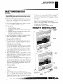
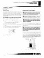
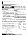
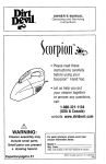
PRODUCT IDENTIFICATION
Fireplace
Cabinet
This fireplace shall not be installed in a bathroom. RemoteReady Models shall not be installed in a bedroom.
Do not use this fireplace as a wood-buming fireplace. Ilse only
Screen
the logs provided with the fireplace.
6.
Do not add extra logs or ornaments such as pine cones, verMICUilte, or rock wool. Using these added items can cause sooting. Do not add lava rock around base. Rock and debris could
fall into the control area of fireplace.
7.
This fireplace is designed to be smokeless. If logs ever appear
to smoke, turn off fireplace and call a qualified service person.
Note: During initial operation. slight smoking could occur due
to log curing and fireplace burning manufacturing residues.
8.
To prevent the creation of soot, follow the instructions in Cleaning and Maintenance, page 29.
9.
Before using furniture polish, wax, carpet cleaner, or similar
products. turn fireplace off. If heated, the vapors from these
products may create a vs hire powder residue within burner box
or on adjacent" alls or furniture.
og
Ignitor Button
Fireplace
Cabinet
10. This fireplace needs fresh air ventilation to run properly. This
fireplace has an Oxygen Depletion Sensing tODS) safety
shutoff system. The ODS shuts down the fireplace if not enough
fresh air is available. See Airlar Combustion and Ventilation.
pages 6 through S. If fireplace keeps shutting off, see Troubleshooting, pages 30 through 32.
Screen
Logs
It. Do not run fireplace
• where flammable liquids or vapors are used or stored.
• under dusty conditions.
2. Do not use this fireplace
IC)
,,„Th-------,
_,/
4 c.------
cook food or burn paper or other
emote
Control
(Optional)
objects.
13. Never place any objects in the fireplace or on logs.
14. Do not use fireplace if any part has been under water. Immediately call a qualified service technician to inspect the room
fireplace and to replace any part of the control system and any
gas control which has been under water.
id!'
07032-01J
in!, if _; hi]
Selector Switch
(Option al)
Ignitor
Button
Control
Knob
Figure 1 - Vent-Free Compact Classic Hearth° Fireplace
piy,14-: ,', :lirlisit www•desatech.com
CIDESA
OPTIONAL REMOTE CONTROL ACCESSORIES
LOCAL CODES
PRODUCT FEATURES
UNPACKING
OPTIONAL REMOTE
CONTROL ACCESSORIES
UNPACKING
1.
(For Remote-Ready Models Only)
There are four optional remote controls that can be purchased
separately for Remote-Ready Models only:
• wall switch
• hand-held ON/OFF remote
• wall thermostat
• hand-held thermostat remote
See Accessories, pages 38 and 39.
LOCAL CODES
Install and use fireplace with care. Follow all local codes. In the
absence of local codes, use the latest edition of The :National Fuel
Gas Code ANSI Z22$. I/NFPA 54*.
*.Available from:
2.
3.
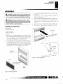
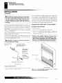
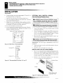
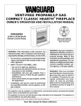
Remove log box and fireplace from carton. IMPORTANT:The
fireplace hood is inside the cardboard protective end wrap on
the left side of fireplace (as viewed from front). A decal is on
the outside of the cardboard end wrap stating hood is enclosed
(see figure 2).
Remove hood from cardboard protective end wrap as shown
in Figure 2.
Remove all protective packaging applied to fireplace for
shipment.
4. Make sure your fireplace includes one hardware packet.
3. Check tireplace for any shipping damage. If fireplace is damaged, pror I ipt's! inform dealer where you bought fireplace.
Hood
Enclosed
Decal
American National Standards Institute, Inc.
1430 Broadway
New York, NY 10018
THS PACKAGE CONTAINS A
FIREPLACE HOOD UNWRAP
CARTON AND RPAAOVE HOOD
BEFORE DISCARDING
PROTECTIVE PACKAGING
Cardboard
Protective
Fireplace End
Wrap
National Fire Protection Association, Inc.
Batterymarch Park
Quincy, MA 02269
PRODUCT FEATURES
SAFETY PILOT
<!
This fireplace has a pilot with an Oxygen Depletion Sensing (ODS)
safety shutoff system. The ODS/pilot is a required feature for vent-tree
room fireplaces. The ODS/pilot shuts off the fireplace if there is not
enough fresh air.
PIEZO IGNITION SYSTEM
This fireplace has a piezo ignitor. This system requires no matches,
batteries, or other sources to light fireplace.
Hood —
Figure 2 - Removing Fireplace Hood
THERMOSTATIC HEAT CONTROL FOR
THERMOSTAT-CONTROLLED MODELS
Thermostat-Controlled models have a thermostat sensing bulb and
a control valve. The thermostat will automatically modulate the heat
output to maintain a consistent room temperature. This results in
greater fireplace comfort. This can also result in lower gas hills.
For more lot
1070,72-0IJ
ASSEMBLY
Assembling Fireplace
N4,MIUMINS.
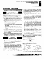
ASSEMBLY
A
WARNING: Always have branch support and
screen in place before operating fireplace. This prevents excessive temperatures on fireplace surfaces.
A WARNING: Failure to position the parts in accordance with these diagrams or failure to use only parts
specifically approved with this fireplace may result in
property damage or personal injury.
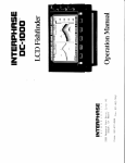
4.
Locate four black phillips sheet metal screws from the hardware packet.
5.
Rotate hood as shown in Figure 4. Make sure hood tabs
point toward fireplace.
6.
Insert hood tabs between baffle and louvers (see Figure 4).
7.
Gently rotate hood to upright position. Make sure hood tabs
are behind louvers and hood is resting on firebox top (see
Figure 4).
8.
Align screw holes on hood with screw holes on firebox top.
9.
Insert screws as shown in Figure 4. Tighten screws firmly.
ASSEMBLING FIREPLACE
Tools Required:
•
Phillips screwdriver
•
5/16" hex wrench
•
slotted screwdriver
•
scissors
1.
Remove two screws that hold fireplace screen in place for shipping. These screws are located near top of screen. Discard
screws. Lift fireplace scree: up and pull out to remove. Set
screen aside until installation !Hs been completed.
2.
Cut two plastic straps to remove the log from the firebox cavity.
3.
An optional blower is available. Seedcressonies, pages 38 and
39. Install optional blower now. Follow installation instructions provided with blower. See page 12 for Remote-Ready
Models or page 14 for Thermostat-Controlled Models.
Sheet Metal Screws
Firebox Top
Figure 4 - Assembling Hood
Figure 3 - Removing Screen
u iiPitz; la! 91.4,114
'07032-01.!
visit www.desatech.com
•ESA
AIR FOR COMBUSTION AND VENTILATION
Providing Adequate Ventilation
Determining Fresh-Air Flow for Fireplace Location
AIR FOR COMBUSTION AND
VENTILATION
A WARNING: This fireplace shall not be installed in
c. caulking or sealants are applied to areas such as
joints around window and door frames, between sole
plates and floors, between wall-ceiling joints, between
a confined space or unusually tight construction
wall panels, at penetrations for plumbing, electrical,
and gas lines, and at other openings.
unless provisions are provided for adequate combustion and ventilation air. Read the following instructions to insure proper fresh air for this and
other fuel-burning appliances in your home.
Today's homes are built more energy efficient than ever. Nev materials, increased insulation, and new construction methods help reduce
heat loss in homes. Home owners weather strip and caulk around
windows and doors to keep the cold air out and the warm air in. During
heating months, home owners want their homes as antight as possible.
While it is good to make your home energy efficient your home
needs to breathe. Fresh air must enter your borne. All fuel-burning
appliances need fresh air for proper combustion and ventilation.
Exhaust fans, fireplaces, clothes dryers, and fuel burning appliances
draw air from the house to operate. You must provide adequate fresh
air for these appliances. This will insure proper venting of vented
fuel-burning appliances.
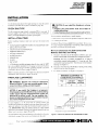
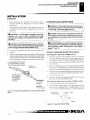
PROVIDING ADEQUATE VENTILATION
The following are excerpts from National Fuel Gas Code, ANSI
21223. I/NEPA 54. Section 5.3, Air for Combustion and Ventilation.
All spaces in homes fall
classifications:
iron
one of he throe following ventilation
1.
Unusually Tight Construction
2.
Unconfined Space
3.
Confined Space
If your home meets all of these three criteria, you
must provide additional fresh air. See Ventilation Air
From Outdoors, page 8.
If your home does not meet all of the three criteria above,
proceed to Determining Fresh-Air Flow For Fireplace
Location, below.
Confined and Unconfined Space
The National Fuel Gus Code. ANSI Z223.1/NEPA 54 defines a
confined space as a space whose volume is less than 50 cubic feet
per 1,000 Btu per hour (4.8 in' per kw) of the aggregate input rating
of all appliances installed in that space and an unconfined space as
a space whose volume is not less than 50 cubic feet per 1,000 Btu per
hour (4.8 in per kw) of the aggregate input rating of all appliances
installed in that space. Rooms communicating directly with the
space in which the appliances are installed*, through openings not
furnished with doors, are considered a part of the unconfined space.
Adjoining rooms are communicating only if there are doorless
passaged\ ays or ventilation grills between them.
DETERMINING FRESH-AIR FLOW FOR
FIREPLACE LOCATION
Determining if You Have a Confined or
Unconfined Space
The information on pages 6 through S
V.
ill help you classify your
Use this work sheet to determine if you have a confined or unconfined space.
space and provide adequate ventilation.
Space: Inaludes the MOM in which you will install fireplace plus any adjoinin2
Unusually Tight Construction
rooms with rloorless passageways or ventilation grills between the rooms.
The air that leaks around doors and windows may provide enough
fresh air for combustion and vemilation. However, in buildings of
unusually tight construction, you must provide additional fresh air.
I.
b.
walls and ceilings exposed to the outside atmosphere
have a continuous water vapor retarder with a rating
of one perm (6 x 1 0 - " kg per pa-sec-in') or less with
openings gasketed or sealed and
cu. ft. (volume otspace)
Example: Space size 16 ft. (length) x 14 P. (width)
S ft. ',Jain)]
height I = 1792 en tt. (volume of space)
If additional ventilation to achommic 10011115 supplied with grillsoropenings, add the volume of these rooms to die total volume of the space
2
Nlutuplv the space volume by 20 to determine the maximum Btuil In
thc spnce can support.
volurnc of space) \ 20 = (Maximum Btud- ir the spice
weather stripping has been added on openable win-
dows and doors and
‘olume of the space (length x width x height))
Length x Width x Height =
Unusually tight construction is defined as construction
where:
a.
1)(2LT111111C the
can support)
Example: 1792 Cu. ft. (volume of space) x 20 4 35,840 (maximum
13tull hr the space can support)
For more informaitioni`',
4 .1 ,,t
:J sfr 31.1
(J,L:1)11J
107032-01J
AIR FOR COMBUSTION AND VENTILATION
Determining Fresh-Air Flow for Fireplace Location (Cont.)
Ventilation Air
AIR FOR COMBUSTION AND
VENTILATION
Continued
VENTILATION AIR
Add the Btu/I fr of all fuel burning appliances in the space.
Bt till Ir
Vent-free fireplace
Ventilation Air From Inside Building
Gas water heater* Btu/I fr
Gas furnace
Btu/Hr
This fresh air would come from an adjoining unconfined space.
Vented gas heater
Bitt/Hr
When ventilating to an adjoining unconfined space, you must
Gas fireplace logs
Biu/Hr
Other gas appliances' d-
Btu/Hr
=
Btu/Hr
Total
provide two permanent openings: one within 12" of the ceiling and
one w ithin 12" of the floor on the wall connecting the two spaces
see options I and 2. Figure 5). You can also remove door into
adjoining room (see option 3. Figure 5). Follow the National Fuel
* Do not include direct - vent gas appliances. Direct - vent draws combustion air from the outdoors and vents to the outdoors.
Gcis Code, A 51.517223. l/NFPA 54, Section 5.3, Air for Combustion
and Ventilation for required size of ventilation grills or ducts.
Example:
30 . 000
Gas water heater
Vent-free fireplace
Total
+
rz
Rtii/Hr
10,000
Btu/Hr
40,000
Blu/l Ir
--,D
A
.0 --
4. Compare the maximum Btu/Ur the space can support with the actual
amount of Btu/Hr used.
Btu/Hr (maximum the space can support)
V ent,Iai3O0 O nlii
Int o Ad
p A corn.
Btu/Hr (actual amount of Btudir used)
Example:
Op
II
35,840 Btu/Hr (maximum the space can support)
A
cRoo
40,000 Btu/Hr (actual amount of Btu/Hr used)
The space in the above example is a confined spac because the actual Btu/
or
g
Rm
Doo r
Adjornng
o
n
Ir used is more than the maximum Btu/Hr the space can support. You must
provide additional fresh air. Your options are as follows:
A.
Rework worksheet, adding the space of an adjoining room. if the
extra space provides an unconfined space. remove door to adjoining
room or add ventilation grills between rooms. See 'owe/or/on Air Frain
... •1.A.N
Inside Building.
B.
Vent room directly to the outdoors. See likaailtnion Air From Outdoors. page 8.
C.
Install a lower B tu/H r fireplace. if low er Btu/H r sOc makes coon,
unconfined.
Figure 5- Ventilation Air from Inside Building
the actual Btu/Hr used is less than the maximum Btu/Hr the space can support,
the space is an unconfined space. You will need no additional fresh air ventilation.
A WARNING: If the area in which the fireplace
may
be operated is smaller than that defined as an unconfined space or if the building is of unusually tight ,
construction, provide adequate combustion and ventilation air by one of the methods described in the
National Fuel Gas Code, ANSI Z223.1/NFPA 54 Section 5.3 or applicable local codes.
,
.17
:'07032-01i
visit www.desatech.com
CIDESA
INSTALLATION
Check Gas Type
Installation Items
Fireplace Clearances
INSTALLATION
Continued
Use the dimensions shown for rough openings to create the easiest
installation (see Built-In Fireplace Installation. page 10).
A CAUTION: If you install the fireplace in a home
garage
• fireplace pilot and burner must be at least 18
inches above floor.
• locate fireplace where moving vehicle will not hit it.
CHECK GAS TYPE
Use the correct gas type (natural or propane/LP) for your unit. If
your gas supply is not correct, do not install fireplace. Call dealer
where you bought fireplace for proper type fireplace.
For convenience and efficiency. install fireplace
INSTALLATION ITEMS
•
where there is easy access for operation, inspection, and
Before installing fireplace, make sure you have the items listed
•
in coldest part of room
below.
An optional blower kit is available from your dealer. See Accessories. pages 38 and 39.11 planning to use blower, follow instructions
provided with blower for power source.
•
external regulator (supplied by installer, for propane/LP units only)
•
piping (check local codes)
•
sealant (resistant to propane/LP gas)
•
equipment shutoff valve *
•
test gauge connection*
•
ground joint union
•
sediment trap
•
tee joint
•
pipe wrench
SCINICe
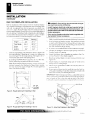
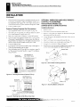
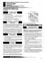
Minimum Clearances For Side Combustible
Material, Side Wall, and Ceiling
A.
Clearances from the side of the fireplace cabinet to any combustible material and wall should follow diagram in Figure 7.
Example: The face of a mantel, bookshelf, etc. is made of
combustible material and protrudes 3 1 /2" from the wall. This
combustible material must be 4" from the side of the fireplace
* A CSA design-certified equipment shutoff valve with 1/8" NPT
tap is an acceptable alternative to test gauge connection. Purchase
the optional CSA design-certified equipment shutoff valve from
your dealer. See Accessories. pages 38 and 39.
opening (see Figure 7).
B.
Clearances from the top of the fireplace opening to the ceiling
should not he less than 36 inches.
C.
For mantel clearances, see Figure 11 on page 11.
Note: If desired, purchase a four-sided brass trim kit for built-in
installations. See Accessories, pages 38 and 39.
MINIMUM CLEARANCE TO
COMBUSTIBLE MATERIALS
FIREPLACE CLEARANCES
Top
A
WARNING: Maintain the minimum clearances
shown in Figure 7. If you can, provide greater clearances from floor, ceiling, and joining wall.
■
If your fireplace is to be recessed into the wall, see Built-In Fireplace
Installation 00 page 10 to secure your fireplace into the wall.
*if Lit :)/ iithit
10 7032- 0
0"
6"
36"
NOTICE: If you install the fireplace in a bedroom
(Thermostat-Controlled Models only), some building
codes require that the fireplace/mantel system be
secured to (or within) a wall. You can position fireplace in an optional cabinet or corner mantel. You can
also recess fireplace into the wall.
If your fireplace is to be used with an optional mantel, the
installation instructions included with your mantel shows an ESA
approved method of attaching the l'ireplace/mantel system to a
wall. IMPORTANT: Only use optional cabinet or corner mantels
specified in this manual. Purchase the optional mantel from your
dealer (see Accessories. pages 38 and 39).
Left and
Bottom
Right Sides and Rear
12 1 /4
1002
8 30
Example
nn
FIREBOX
1 1/4
rani 7/8
MMMMMM 7/16
4 6 8 10 12 14 16*
IN
• Nfinimum lb inches from Side Wall
Figure 7- Minimum Clearance for Combustible to Wall
4 , •11 0 visit www.desatech.com
MESA
INSTALLATION
Built-In Fireplace Installation
NaillikalittiliklaRatttadnAls ,
INSTALLATION
Continued
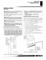
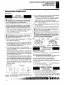
BUILT-IN FIREPLACE INSTALLATION
A WARNING: If pre-wiring, do not connect wiring to
Built-in installation of this fireplace involves installing fireplace
into a framed-in enclosure. This makes the front of fireplace flush
with wall. An optional brass trim kit accessory is available (see
Accessories', pages 38 and 39). Brass trim will extend past sides of
fireplace approximately 1/2 inch. This will cover the rough edges of
the wall opening. If installing a built-in mantel above the fireplace,
you must follow the clearances shown in Figure II ,page 11. Follow
the instructions below to install the fireplace in this manner.
'
Actual
Height
Front Width
1.
2.
any electrical source at this time.
Install fireplace electrical outlet and connect wiring
to outlet before connecting to electrical source. The
fireplace electrical outlet is included with the GA3450T
blower accessory.
Only use the fireplace electrical outlet supplied with
the GA34507 blower accessory.
Note: A qualified installer should make all electrical connections.
• Framig
26"
.
261t
26 3/4"
•
26 7/5"
Depth
9 I /2"
10 1 /2"
Bottom
3/4"
3/4"
3.
Install gas piping to fireplace location. This installation includes
all approved flexible gas line (if allowed by local codes) after
the equipment shutoff valve. The flexible gas line must be the
last itern installed on the gas piping.
4.
If you have not assembled firebox, follow instmetions on page 5.
5.
Carefully set fireplace in front of rough opening with back of
Ii replace inside wall opening.
Frame in rough opening. Use dimensions shown in Figure 8 for
the rough opening. If installing in a corner, use dimensions
shown in Figure 9 for the rough opening. The height is 26 7/s"
6.
which is the same as the wall opening above.
7.
If installing GA3450T blower accessory, do so at this time.
Follow instructions included with blower accessory.
S. Attach fireplace to wall studs using nails or wood screws
Note: If not installing blower accessory, you may wish to run
electrical wiring to your fireplace for future blower installation (see Accessories. pages 38 and 39). Use only approved
three-wire electrical wiring.
Attach flexible gas line to fireplace gas regulator. See Connecting Fireplace to Gas Supply, page 18.
Bend four nailing flanges on outer casing with pliers (see
Figure It)).
through holes in nailing flange.
9. Check all gas connections for leaks. See Checking Gas Connections. page 19.
W. If using optional brass trim kit, install the trim after final finishing and/or painting of wall. See instructions included with
brass trim accessory for attaching brass trim.
IMPORTANT: When finishing your firebox, combustible materials
such as all board. gypsum board, sheet rock, drywall, plywood, etc.
inay he hinted up next to the sides and top edge of the firebox.
Combusshle materials should never- overlapthe firehox front facing.
10 Itin
ads
•
26718"
3/4" Off
The Floor
Minimum
Figure 8- Rough Opening for Installing in Wall
Nails or
Wood
Screws \
365 /a"
26'fi."
51 3/4“
Figure 9 - Rough Opening for Installing in Corner
For more information,
Figure 10 - Attaching Fireplace to Wall Studs
z
INSTALLATION
Built-In Fireplace Installation (Cont.)
Optional Mantel Installation
INSTALLATION
Continued
,
A WARNING: Do not allow any combustible materials to overlap the firebox front facing,
NOTICE: If your installation does not meet the minimum clearances shown, you must do one of the
following:
• raise the mantel to an acceptable height
• remove the mantel
,
IMPORTANT: Noncombustible materials such as brick, tile, etc.
may overlap the front facing, but should never cover any necessary
openings nice touvereu slots.
A WARNING: Do not allow noncombustible materials
to cover any necessary openings like louvered slots.
A WARNING: Never modify or cover the louvered
slots on the front of the firebox.
A WARNING: Use only noncombustible mortar or
adhesives when overlapping the front facing with
noncombustible facing material.
Mantel Clearances for Built-In Installation
If placing mantel above built-in fireplace, you must meet minimum
clearance between mantel shelf and top of fireplace opening.
NOTICE: Surface temperatures of adjacent walls and
mantels become hot during operation. Walls and
mantels above the firebox may become hot to the
touch. If installed properly, these temperatures meet
the requirement of the national product standard.
Follow all minimum clearances shown in this manual.
OPTIONAL MANTEL INSTALLATION
Note:
Refer to instructions provided with the mantel for assembly
instructions. Refer to the following instructions for system installation. Refer to instructions on page 5 for fireplace assembly. Blower
accessory should be installed if it is being used (see Installing
Blower Accesvory GA34507: pages 12 through 16).
1.
Unscrew four brass Screws that attach top louver to fireplace.
Remove louver from fireplace and set aside.
2.
Place fireplace on wood base.
3.
Place mantel around fireplace/base assembly.
4.
Assemble brass trim kit. See
5.
Firmly snap brass trim kit on shoulder screws. Shoulder screws
are located on fireplace cabinet (see Figure 12).
6.
Align brass trim kit for flush fit around opening.
7.
Use two 3" wood screws provided and attach fireplace base to
Note:
All vertical
measurements
are from top of
fireplace
opening to
bottom of
mantel shelf. All
measurements
are in inches.
page 12.
wooden base (see Figure 12).
8.
Place base assembly next to wall at installation location.
9.
Remove brass trim kit and mantel. Be careful not to damage
wall or mantel.
Hole for 3"
Wood Screw
for Attaching
Fireplace to
Mantel
Mantel Shelf
Assembling Brass Trim,
Shoulder Screws
lair 8:4_
i 'Ns Hole for 3'
.
Wood Screw
I
..
for Attaching
" --- . .. , I
1
Fireplace to
Assembled
I Wooden Base
Brass Trim
Side of Firebox
Figure 12 - Attaching Brass Trim to Fireplace
Figure 11 - M1,71177UM Mantel Clearances for Built-In Installation
1111.32 '15.11p.ii,, ag„inil;
ILIG.132 GI,
visit www.desatech.corn
CDESA
INSTALLATION
Optional Mantel Installation (Cont.)
Installing Blower Accessory GA34507" in Remote-Ready Models
INSTALLATION
Continued
10. Attach wood base to floor with two 1 3/4'' black screws provided (see Figure 13). lithe floor is concrete use anchor method
(see Attaching Wood Base to Solid Floor, page 17).
11. Install gas line. See Connecting To Gas Supply, pages 17 and IS.
12. Check for leaks. See Checking Gas Connections, page 19.
13. Place mantel around fireplace. Be careful not to damage wall
or mantel.
14. Place brass trim kit on the shoulder screws located on the side
and top of the fireplace. Firmly snap the brass trim over the
shoulder screws on fireplace (see Figure 12, page 11).
15. Adjust assembly to remove any gaps. Attach remaining two 3''
wood screws from hardware pack through openings inside of
fireplace sides into the mantel. The openings are located at top
behind the area for the brass louvers (see Figure 12, page II).
16. Reinstall top brass louvers.
1 3 /4"
...-----
Screw
_..-
—
i'\
•••••••
-------------•0101........111.1
-
Wood Base
Set
Screws
Adjusting
Plate
Side Brass Trim—'
Figure 14 - Assembling Brass Trim
INSTALLING OPTIONAL BLOWER ACCESSORY
GA3450T IN REMOTE-READY MODELS
Removing Upper Louver Assembly and Branch
Support
To install the blower accessory, you must first remove the upper
louver assembly.
I. Lift screen off fireplace and remove log set if installed.
2.
3.
4.
2.
3.
4.
5.
6.
7.
S.
Remove packaging from three remaining pieces of brass (rim.
Locate two adjUSting plates with set screws, and two shims
in the hardware packet.
Align shim under adjusting plate as shown in Figure 14.
Slide one end of adjusting plate/shim in slot on mitered edge
of top brass trim (see Hgure 14).
5.
P i,PON e 2 screws from each side of branch support and pull
branch support out (see Figure 15).
Remove 4 brass-plated Screws from upper louver assembly
(see Figure 15). Save these screws.
Pull upper louver assembly straight out from the cabinet. Be careful not to scratch the paint. Set louver assembly and screws aside.
Open lower louver door by swinging door down (see Figure 16,
page I 3 I.
Blower Bracket
Mounting Holes
Lii—il I
Upper Louver
Assembly
iill—t?
,I
I
Slide other end of adjusting plate/shim in slot on mitered edge
of side brass trim (see Figure 14).
While firmly holding edges of brass trim together. tighten both
set screws on the adjusting plate with slotted screwdriver.
Repeat steps 1 through 6 for other corner.
Set brass assembly aside for later installation.
Top Brass Trim
Mitered Edge
Figure 13 - Attaching Wood Base to Floor
Assembling Brass Trim (Brass trim shipped with
mantel)
/
Slot
I
e
Se'
Branch Support
Figure 15 - Removing Upper Louver Assembly and Branch
Support
For more information,'
107032-01J
INSTALLATION
Installing Blower Accessory GA34507 in Remote-Ready Models (Cont)
INSTALLATION
Continued
5.
In top of the fireplace cabinet, locate the four mounting holes
on the outer easing. Align these tour holes with those on the
blower bracket assembly. Attach blower bracket assembly to
the outer casing with 4 #10 screws provided (see Figure 16).
6.
Route the wire harness through the hole in left side of baffle.
Pull wire harness through lower opening on the side of the
valve cover shield. (see Figure 16).
7.
Note: If you are using a mantel with your fireplace, use the
Following instructions. If your fireplace is built-in, see For Built-1n
Installation, page 14_
Insert the 4 wire harnesses into one of the round holes in the rear
of the valve cover shield and through the rectangular hole in the
Front of shield (see Figure 16).
8.
Reconnect red wire to switch position 3. Reconnect blue wire
1.
Install snap bushings found in hardware kit into both holes in
rear of valve cover shield.
9.
2.
Make sure the wire harness is firmly connected to the terminals on the blower bracket assembly.
3.
Note the wire locations on back of AUTO/OFF/ON switch. The
terminals on back of switch are numbered 1,2, and 3, Carefully
remove red wire from terminal 3 and blue wire from terminal 1.
Black wire can remain on middle terminal 2 (sec Figure 16).
4.
Carefully disconnect green and white wires at their insulated
Installing Blower Accessory
A CAUTION: Label all wires prior to disconnection
when servicing controls. Wiring errors can cause
improper and dangerous operation.
A CAUTION: Verify proper operation after servicing.
connectors (see Figure 17).
Blower Bracket
Assembly
Screw
I
to switch position t . Reconnect green and white wires.
Install the switch plate on the valve cover shield with 2 #I0 screws
provided (see Figure 18). Route power cord out of the cabinet by
inserting it through the bushing on the outer casing (see Figure
16). Plug fan kit into 120-Volt grounded power supply and test
operation. Note: When switch is in the AUTO position, the fan
will start after the fireplace has run for a few moments. The fan
ill continue to run for several moments after the fireplace has
been turned off. When switch is in the ON position, the fan will
run until turned to OFF. Reinstall upper louver assembly (see Figure 15, page 12) and branch support. Close lower louver door.
Wire
Wiring Routing
Harness Hole in Baffle
-
Bathe
Snap
Blower
Mounting
Figure 17 - Wiring Diagram For Blower Accessory Standard
Installation
alve Cover
hield
Switcl
Plate
Plate
Black Red —
Figure 18 - Installing Switch Plate to Valve Cover Shield
Wire Harness
Valve Cover Shield
Lower Louver Door
Figure 16 Installing Blower Bracket Assembly
-
Lli LIJILeS
107032-C1J
1044 , oth visit www.desatech.com
*ESA
INSTALLATION
Installing Blower Accessory GA3450T in Remote-Ready Models (Cont.)
Installing Blower Accessory GA3450T In Thermostat-Controlled Models
INSTALLATION
Continued
For Built-In Installation
5.
6.
A WARNING: A licensed electrician must connect the
Test to make sure the blower is working properly.
Reinstall upper louver assembly (see Figure 15, page 12) and
close lower louver.
wiring harness to electrical supply following all local
codes. Electrician must provides clamp on the box cover
Extension Cord
to secure the wiring. Wiring should be routed through the
Use _A tension cord if needed. The cord must have a three-prong,
bushing in the hole on the outer casing of fireplace.
gt,ic 'ding plug and a three-hole receptacle. Make sure cord is in good
shak„. It must be heavy enough to carry the current needed. An
1
Install a snap bushing found in hardware kit into one of the holes
undarsims(I coni will cause a drop in line voltage. This will result in
loss of power and overheating. Use a No. 16 AWG cord for lengths
less than 50 feet.
2
on rear of valve cover shield. The other hole is for a strain relief
clamp (not supplied) to secure incoming electrical supply.
Follow steps 2 through 6 in Installing Blower Accessory, page 13.
3.
A licensed electrician must follow the wiring diagram to connect incoming electrical supply to fan kit wiring harness (see
Figure 19).
4.
Plug power cord to the outlet receptacle (not provided) as shown
in Figure 20. w in power cord and tie it up with the plastic wire
strap (see Figure 20). Set the cable bundle between the burner
bracket and outer casing, away from the burner.
INSTALLING OPTIONAL BLOWER
ACCESSORY GA3450T IN THERMOSTATCONTROLLED MODELS
Removing Upper Louver Assembly
To install the blower accessory, you must first remove the upper
louver assembly,
I. Remove 4 screws from upper louver assembly (see Figure 211,
Save these screws.
2. Pull upper louver assembly straight out from the cabinet. Be careful not to scratch the paint. Set louver assembly and screws aside.
Blower Bracket
Mounting Holes
Figure 19 - Wiring Diagram For Blower Accessory Built-In
Installation
Blower Bracket
Screw /.
E
,---- 'n-,„Wire Harness
11
-
V
Brass Screws
e I \
Outlet
Receptacle
(not
Included)
0 Power Cord
Upper Louver
Assembly
Figure 21 - Removing Upper Louver Assembly
Clamp
- rz--4,
.. n
Connector
(not
included)
Switch
Plate
Wire
Plastic Wire Strap
-"----,\
:- -,. ---
Lower Louver Door
Figure 20 - Installing Blower Bracket Assembly
For more informatiaii;'
4 4,
.f:DJJJ
107032-Old
INSTALLATION
Installing Blower Accessory GA34507 in Thermostat-Controlled Models (Cont.)
INSTALLATION
Continued
3.
Removing Valve Cover Shield
1.
Open bottom louver assembly by swinging the assembly down
(see Figure 22).
2.
Using short Phillips screwdriver, remove the screw under the
center of the branch support. Rotate valve cover shield clockwise and slide out.
IMPORTANT.' Do not remove shoulder SCFCNV on the kit side
of valve cover shield. Slide the valve cover shield off of the
4.
Carefully disconnect green and white wires at their insulated
connectors (see Figure 24).
5.
In top of the fireplace cabinet, locate the four mounting holes
on the outer casing. Align these four holes with those on the
blower bracket assembly. Attach blower bracket assembly to
the outer casing with 4 #10 screws provided (see Figure 23).
6.
Route the wire harness through the hole in left side of baffle.
Pull ,A ire harness through lower opening above where the
valve shield was removed. (see Figure 23).
shoulder screw (see Figure 22).
Note:If you do not have a short Phillips screwdriver, the screen,
logset, and branch support must be removed so a longer screwdriver may be used. See Removing tipper Louver Assembly
and Branch Support, page 12.
Branch Support
Shoulder
Screw ,
Note the wire locations on hack of AUTO/OFF/ON switch.
The terminals on back of switch are numbered 1, 2, and 3.
Carefully remove red wire from terminal 3 and blue wire from
terminal 1. Black wire can remain on middle terminal 2 (see
Figure 23).
Blower Bracket
Assembly
Remove Valve Cover [...:::1
Screw
Shield
\
L
or
2 • _,
.-
i
1
->1 ,
I
Baffle
151-Thr•---•
- ,.. '
•
-........"./C
Power
Switch
,
,
OW ,r. -I.,
IA-
Wiring Routing
Hole in Baffle
Blower
iMounting
kg-L
Screw
\
Wire Harness
,,
,,--
,.
..•
40 -,
1
•-•:,•-•••
...
..-----
1
Switch
772'
Plate Blue
Snap Bushings
Bottom Louver Assembly
Black
Figure 22- Removing Valve Cover Shield
v-
Installing Blower Assembly
Valve Cover Shield
A CAUTION: Label all wires prior to disconnection
Wire ''Harness
Box Cover
Figure 23 - Installing Blower Bracket Assembly
when servicing controls. Wiring errors can cause
improper and dangerous operation.
A CAUTION: Verify proper operation after servicing.
Note: If you are using a mantel with your fireplace, use the
following instructions. If your fireplace is built-in, see For Built-hi
Installation on page 14.
Install snap bushings found in hardware kit into both holes in
rear of valve cover shield.
2. Make sure the wire harness is firmly connected to the terminals
on the blower bracket assembly.
;Di
107032 -012
inDie
Figure 24 - Wiring Diagram For Blower Accessory Standard
Installation
.n visit www.desatech.com
MESA.
INSTALLATION
Installing Blower Accessory GA3450T in Thermostat-Controlled Models (Cont.)
INSTALLATION
Continued
7.
Insert the 4 wire harness into one of the round holes in the rear
of the valve cover shield and through the rectangular hole in
4. A licensed electrician must follow the wiring diagram to connect incoming electrical supply to fan kit wiring harness (see
the front of shield (see Figure 23, page 15).
Figure 26).
S. Reconnect red wire to switch position 3. Reconnect blue wire
to switch position 1. Reconnect green and white wires.
Plug power cord to the outlet receptacle (not provided) as shown
9. Install the switch plate on the valve cover shield with 2 #10
screws provided (see Figure 25). Reinstall the valve cover
shield. Route power cord out of the cabinet by inserting it
through the bushing on the outer casing (see Figure 23, page
15). Plug fan kit into 120-Volt grounded power supply and test
operation. Note: When switch is in the AUTO position, the
fan will start after the fireplace has run for a few moments.
The fan will continue to run for several moments after the fireplace has been turned off. When switch is in the ON position,
the fan will ran until turned to OFF. Reinstall upper louver
assembly and hood if previously removed. (see Figure 21, page
14). Close lower louver door.
the plastic \s ire strap (see Figure 27). Set the cable bundle be-
in Figure 27. Wind the extra cable in power cord and tie it up with
tween the burner bracket and outer casing, away from the burner.
6.
Reinstall valve cover shield.
7.
Test to make sure the blower is working properly.
S. Reinstall upper louver assembly and hood if previously removed.
(see Figure 21, page 14). Close lower louver door.
Valve Cover
Shield
Figure 26 - Wiring Diagram For Blower Accessory Built-In
Installation
Blower Bracket
Assembly \
Switch
Plate
Screw
Wire
Harness
Screw
Figure 25- Installing Switch Plate to Valve Cover Shield
For Built-In Installation
A WARNING: A licensed electrician must connect
kI
Switch
Plate
the wiring harness to electrical supply following all
local codes. Electrician must provide a clamp on the
box cover to secure the wiring. Wiring should be
routed through the bushing in the hole on the outer
casing of heater.
Follow instructions Removing Valve Cover Shield (page 15), then
Install a snap bushing found in hardware kit into one of the holes
on rear of valve cover shield. The other hole is for a strain relief
clamp not supplied) to secure incoming electrical supply.
2.
Follow steps 2 through 6 in Installing Blower Assembly, page 15.
3.
Remove black plastic strain relief and power cord from switch
plate. The power cord supplied will not be used in built-in installations. Pop in the plastic snap bushing found in hardware
kit into the hole left by supply cord/strain relief
Plastic Wire Strap
Also remove black wire from middle switch terminal 2.
Valve Cover
Box
Shield
Cover
caamp isonnector
(not included)
Figure 27- Installing Blower Bracket Assembly
For more information, t ?0,4,4/ 47/,;j ch.3-Lise,z/J,L;Din
107032-01,1
INSTALLATION
installing Blower Accessory 0A3450T in Thermostat-Controlled Models (Contj
Attaching Wood Baa. to Solid Floor
Connecting to Gas Supply
INSTALLATION
Continued
CONNECTING TO GAS SUPPLY
Extension Cord
se extension cord if needed. The cord must have a three-prong,
grounding plug and a three-hole receptacle. Make sure cord is in good
shape. It must be heavy enough to carry the current needed. An
undersized cord will cause a drop in line voltage. This will result In
loss of power aid overheating. Use a No. lii AWG cord for lengths
less than 50 feet.
ATrACHING WOOD BASE TO SOLID FLOOR
For attaching base to solid floors (concrete or masonry)
Note: Floor anchors and mounting screws are in hardware package.
The hardware package is provided with fireplace.
1, Drill holes at marked locations using 5/16 drill bit. For solid
floors (concrete or masonry), drill at least I deep.
2. Fold floor anchor as shown in Figure 28.
3, Insert floor anchor (wings first) into hole. Tap anchor flush
to floor.
4. Insert mounting screws t .ough base and into floor anchors.
5. Tighten screws until base is firmly fastened to floor.
aw fr-
A WARNING: Thisappliance requircsa45° maleflare
fitting 5/8-18 UNF (Unified National Fine Thread) inlet
connection and the flexible gas line provided.
A WARNING: A qualified service person must connect fireplace to gas supply. Follow all local codes.
A WARNING: Never connect natural gas fireplace to
private (non-utility) gas wells. This gas is commonly
known as wellhead gas.
IMPORTANT For natural gas, check gas line pressure befOre
connecting fireplace to gas line. Gas line pressure must he no greater
than 14 inches of water. If gas line pressure is higher, heater regulator
damage could occur.
CAUTION: Never connect propanelLP fireplace
directly to the propane/LP supply. This fireplace
requires an external regulator (not supplied). Install
the external regulator between the fireplace and propane/LP supply.
For propane/I .P units, the installer must supply an external regulator The external regulator will reduce incoming gas pressure. You
must reduce incoming gas pressure to between II and 14 inches of
ater. If you do not reduce incoming gas pressure, fireplace
regulator damage could occur. Install external regulator with the
cut pointing dos n as shown in Figure 29. Pointing the vent down
protects it from freezing rain or sleet.
External Regulator
Propane/LP
Supply Tank
Figure 28 - Folding Anchor
Vent Pointing Down
Figure 29 - External Regulator With Vent Pointing Down
;Uf
107032-00
inh!)4tJ1
dn
visit www.desatech.com
•ESA
INSTALLATION
Connecting To Gas Supply (Cont.)
Connecting Fireplace to Gas Supply
INSTALLATION
Continued
A CAUTION: Use only new, black iron or steel pipe.
Internally-tinned copper tubing may be used in certain areas. Check your local codes. Use pipe of 1/2"
or greater diameter to allow proper gas volume to
fireplace. If pipe is too small, undue loss of volume
will occur.
We recommend that you install a sediment trap in supply line as
shown in Figure 30. Locate sediment trap where it is within reach for
cleaning. Install in piping system between fuel supply and heater.
Locate sediment trap where trapped matter is not likely to freeze. A
sediment trap traps moisture and contaminants. This keeps them
from going into fireplace controls. If sediment trap is not installed
or is installed wrong. fireplace may not run properly.
Installation must include an equipment shutoff valve, union, and
CONNECTING FIREPLACE TO GAS SUPPLY
plugged 1/8" NIT' tap. Locate NPT tap within reach for test gauge
hook up. NPT tap must be upstream from heater (see Figures 30).
Installation Items Needed
shutoff valve in an accessible
IMPORTANT: Install equipment
. .
location. The equipment shutoff valve is for turning on or shutting
off the gas to the appliance.
Cheek your building codes for any special requirements for locating
equipment shutoff valve to fireplaces.
Apply pipe joint sealant lightly to male NPT threads. This will
prevent excess sealant from going into pipe. Excess sealant in pipe
could result in clogged fireplace valves.
A WARNING: Use pipe joint sealant that is resistant
to
• Phillips screwdriver
• sealant (resistant to propane/LP gas. not provided)
I.
Remove screws that attach branch support to fireplace (see
Figure 31. Carefully lift up branch support and remove from
fireplace (see Figure 31).
NOTICE: Most building codes do not permit concealed gas connections. A flexible gas line is provided to allow accessibility from the fireplace (see
Figure 31). The flexible gas supply line connection to
the equipment shutoff valve should be accessible.
liquid petroleum (LP) gas.
Approved Flexible
Gas Line
GSA Design-Certified
Equipment Shutoff Valve
With 1/8 1 NPT Tap'
c%.
PROPANE/LP
Iv%From
..,1
,
Minimum : ', '
External
Regulator (11 11
L
W.C”to14"
W.C. Pressure)
NATURAL
Branch Si
From Gas Meter
(5" W.C.** to 10.5 1 '
virlio1N.C. Pressure)
Pipe Nipple Gap Tee Joint
Sediment Trap
Figure 30 - Gas Connection
Flexible Gas Line
* Purchase the optional CS A design-certified equipment shutoff valve f torn
■ our dealer. See Acressoriev,
pages 38 and 39.
For more information; 4
Figure 31 - Removing Branch Support From Fireplace
(Thermostat-Controlled Model Shown)
take. -4
07C12 1.1
INSTALLATION
Connecting Equipment shutoff Valve To Heater Control (Cont.)
Checking Gas Connections
rt. , .',..1.',.,:rtatlett011iffiliiMING111.111111111111111111.
INSTALLATION
Continued
2.
3.
Route flexible gas line, included, from fireplace control to
equipment shutoff valve through side or rear access boles in
outer easing.
Apply pipe joint sealant lightly to male threads of gas connector attached to flexible gas line/equipment shutoff valve (see
Figure 32).
A CAUTION: k4oid damage to regulator.
NOld gas
regulator with wrench when connecting it to gas
CHECKING GAS CONNECTIONS
A WARNING: Test all gas piping and connections,
internal and external to unit, for leaks after installing
or servicing. Correct all leaks at once.
A WARNING: Never use an open flame to check for
a leak. Apply a noncorrosive leak detection fluid to all
joints. Bubbles forming show a leak. Correct all leaks
at once.
piping and/or fittings (Thermostat-Controlled Models Only).
A CAUTION: Avoid damage to gas control. Hold gas
A CAUTION: Make sure external regulator has been
installed between propane/LP supply and fireplace.
See guidelines under Connecting to Gas Supply,
pages 17 and 18.
control with wrench when connecting it to gas piping
and/or fittings (Remote-Ready Models Only).
4.
5.
Check all gas connections for leaks. See Checking Gas Connections.
Replace branch support back into fireplace. Feed flexible gas
line into fireplace base area while replacing branch support. Make
sure the entire flexible gas line is in fireplace base area. Reattach branch support to fireplace with screws removed in step 1.
To Gas Regulator (Thermostat.
ControlledModels) or Control
Valve (Remote-Ready Models)
See.
tetra ,
Equipment
Shutoff Valve
• a
rta
Flexible Gas Line
from Fireplace
Gas Regulator
Provided With
Fireplace
Pressure Testing gas Supply Piping system
Test Pressures In Excess Ot 1/2 PSIG (3.5 Vra)
I. Disconnect appliance with its appliance main gas valve (control
valve) and equipment shutoff valve from gas supply piping system. Pressures in excess of 1/2 psig will damage heater regulator.
2. Cap off open end of gas pipe where equipment shutoff valve
was connected.
3. Pressurize supply piping system by either openingpropane/LP supply tank valve for propane/LP gas or opening main gas valve located on or near gas meter for natural gas, or using compressed air.
4. Check all joints of gas supply piping system. Apply noncorrosive
leak detection fluid to all joints. Bubbles forming show a leak.
5.
6.
%Ns
PROPANE/LP
To External
Regulator
NATURAL
To Gas Supply
Figure 32 - Attaching Flexible Gas Line to Equipment Shutoff
Valve
Correct all leaks at once.
Reconnect fireplace and equipment shutoff valve to gas supply. Check reconnected fittings for leaks.
Test Pressures Equal To or Less Than 1/2 PSIG (3.5 kPa)
Close equipment shutoff valve (see Figure 331.
2. PressuPze supply piping system by either opening propaneL.P supply tank valve for propane/LP gas or opening main gas valve located on or near gas meter for natural gas, or using compressed air.
I.
I
Equipment
Shutoff Valve
Open
\)1
\.
\
Closed
Figure 33 - Equipment Shutoff Valve
D.? n131'
107032 C7.]
;lig
visit www.desatech.com
MESA
INSTALLATION
Checking Gas Connections (Cont.)
Optional Wireless Hand-Held Remote Control Accessories [Remote-Ready Models Only]
INSTALLATION
Continued
3
Check all joints from gas meter to equipment shutoff valve for
natural gas or propane/LP supply to equipment shutoff valve
for prepanefLP (see Figures 34 or 35). Apply noncorrosive
leak detection fluid to all joints. Bubbles forming show a leak.
4. Correct all leaks at once.
Pressure Testing Fireplace Gas Connections
1.
Open equipment shutoff valve (see Figure 33. page 19).
2.
Open main gas valve located on or near gas meter for natural
gas or open propane/LP supply tank valve.
3.
Make sure control knob of fireplace is in the OFF position.
4.
OPTIONAL WIRELESS HAND-HELD REMOTE
CONTROL ACCESSORIES
Remote-Ready Models Only
(GHRCB Series & GHRCTB Series)
Installing Receiver
I.
Remove screws.
2.
Disconnect switch wires from the control valve.
3.
Remove switch plate (see Figure 36). Discard switch plate
after removing. Save the screws.
4.
Check all joints from equipment shutoff valve to gas regulator
(Thermostat-Controlled Models), or to gas control valve (RemoteReady Models) (see Figures 34 or 35). Apply noncorrosive leak
detection fluid to all joints. Bubbles forming show a leak.
Locate the battery clip mounted on the back of the receiver
(see Figure 37).
5.
Slide 9-volt battery (not included) through the clip.
6.
Attach the terminal wires to the battery (see Figure 371.
Correct all leaks at once.
7.
Connect wires as shown in Figure 38, page 21.
6.
Light fireplace (see Operating Fireplace, pages 23 through 27).
Check all other internal joints for leaks.
8.
Install remote receiver unit onto fireplace base using the two
screws removed in step one (see Figure 38, page 21).
7.
Turn off fireplace (see To Turn Off Gas to Appliance, page 24
for Thermostat-Controlled Models or page 25 for RemoteReady Models).
5.
Equipment
ch. I+n1f Unlun
Switch Plate
Scre
Red Wire
Gas Regulator or
Gas Control Valve
Black
Wire
Propar
Supply
Tank
Figure 36 - Switch Plate and Wiring Harness
Figure 34 - Checking Gas Joints (Propane/LP Only)
Gas Regulator or
Gas Control Valve
rminal
res
Equipment
c
Shutoff Valve
9-Volt Battery
Figure 37 - Attaching Battery to Receiver
Gas
Figure 35- Checking Gas Joints (Natural Gas Only)
For more information;11
7 07032-0 1 J
INSTALLATION
Optional Wireless Hand-Held Remote Control Accessories (Remote-Ready Models Only] (Cont.)
Optional Wall Mounted Thermostat - GWMT1 [Remote-Ready Models Only]
"ISUINUMMIONIMMilk
INSTALLATION
Continued
Remote
Receiver
OPTIONAL WALL MOUNTED THERMOSTAT GWMT1
(Remote-Ready Models Only)
d Wire
A WARNING: Read and follow installation instruc-
tions. Installation should be dor?, ■ py a qualified
installer familiar with low-voltage WLi.g procedures.
Black Wire
WARNING: Do not connect this thermostat to any
electrical source! Electrical shock and/or fire hazard
will occur.
Wire Harness'
Wires from
Valve
1.
Connect one terminal of 25 ft. wire to bottom contact of switch
(see Figure 41).
2.
Connect remaining wire terminal to the "TH" terminal on the
control valve. Make sure that wire terminals are in the positions on your unit as pictured in Figure 41. If wires are not
crossed- the thermostat will not work.
Red Wire
Black Wire
-
Figure 38 - Installing Remote Receiver
3.
I` Wire harness provided in the fireplace hardware pack.
Installing 9-Volt Battery in Hand-Held Remote
Control Unit
1.
Remo‘e battery cover on hack of remote control unit.
2.
Attach terminal wires to the battery ([lot included). Place battery into the battery housing.
3.
Replace battery cover onto remote control unit.
Battery Cover
Terminal
Wires
Remote
Control Unit
9-Volt
Battery
Route the 25 ft. wire to a convenient location to mount your
thermostat (no outside wall). IMPORTANT. The wire may be
shortened but must not he lengthened.
The thermostat should be mounted 54" above the floor in a
location where there is good air circulation. Avoid heat sources
such as lamps, direct sunlight, fireplace, or heat and air .Jonditinning ducts.
4.
Gently remove the cover of the thermostat from the base. Grasp
the sides of the cover firmly and pull to separate from the base.
5.
Feed the electrical wires through the rectangular slots on each
side of the base (see Figure 42, page 22).
A WARNING:
Do not connect the thermostat to a
power source. Electrical shock and/or a fire hazard
will occur.
Switch on Gas
Fireplace
Figure 39 - Installing Battery in Hand-Held Remote Control Unit
(GHRCB Series)
Control
Valve y
Terminal Wires
9-Volt
Battery
Battery
Housing
/
zr
4
Remote
Control Unit
Battery Cover
Figure 40 - Installing Battery in Hand-Held Remote Control Unit
(GHRCTB Series)
JJJ 5j.e /1,144 .., 11,.. Ong
707032-073
One
terminal
of 25 ft.
wire
To Wall
Thermostat
or Switch
l15l=
'I
—
?0
7
To Wall
Thermostat
or Switch
Figure 41 - Connecting Wire Terminals
visit www.desatech.com
MESA
INSTALLATION
Optional Wall Mounted Thermostat - GWMT1 (Remote-Ready Models Only] (Cont.)
Optional Wall Switch - OWM52 (Remote-Ready Models Only]
Installing Log Set and Screen
INSTALLATION
Continued
6.
Connect one bare wire end to each terminal ("W" and "R")
the thermostat base (see Figure 43).
7.
8.
Install the base onto the wall with the provided screws.
Move the temperature adjustment back and forth to insure the
bitnetal is free from restrictions.
9.
Replace the cover onto the base. (Upon installation. the thermostat must be allowed to stabilize at room temperature for
a minimum of 30 minutes for proper operation).
OPTIONAL WALL SWITCH - GWMS2
(Remote-Ready Models Only)
A WARNING: Read and follow installation instructions. Installation should be done by a qualified
installer familiar with low-voltage wiring procedures.
A WARNING: Do not connect this switch to any electri-
10. Set switch on fireplace to Auto position.
11. Sct the temperature adjustment to the desired setting. This thermostat has been electronically calibrated at the factory. No adjustment or leveling is necessary.
Feed wires through rectangular slots
cal source! Electrical shock and/or fire hazard will occur. I
1.
2.
3.
111
a
Connect one terminal of 25 ft. wire to bottom contact of switch
(see Figure 41. page 21).
Connect remaining wire terminal to the -rir terminal on the
control valve. Make sure that wire terminals are in the positions on your unit as pictured in Figure 41, page 21. If wires
are not "crosser the thermostat will not work.
Route the 25 ft. wire to a convenient location to mount your
wall switch (no outside walls).
.2
A WARNING: Do not connect the switch to a power
source. Electrical shock and/or fire hazard will occur.
Figure 42 - Back View of Thermostat Base
Terminal "W"
.7
IMPORTANT: The wire may be shortened but must not be
lengthened.
4. Connect one hare wire end to each of the terminals of the provided wall switch.
5. Install the wall switch and cover in the wall.
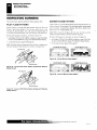
INSTALLING LOG SET AND SCREEN
Remove log packaging material and discard packaging. Gently place log on burner support (see Figure 44). The log should
fit flat against top of burner support and log locator tabs fit
into the slots under the log. Do not allow log to contact flame.
I( flame contact; log, SOCA will he created
Terminal
Reattach screen by placing the notches in the screen frame
its er the shoulder screws and pushing down.
Screw
Figure 43 - Thermostat Base Terminals "W" and "R"
Log
411
Figure 44 - Installing Log and Screen
For more informaiiiitr,
107032-01J
OPERATING FIREPLACE (THERMOSTAT-CONTROLLED MODELS)
For Your Safety Read Before Lighting
Lighting instructions
OPERATING FIREPLACE
I THERMOSTAT-CONTROLLED MODELS I 4.
FOR YOUR SAFETY
READ BEFORE LIGHTING
A WARNING: If you do not follow these instructions
exactly, a fire or explosion may result causing property damage, personal injury or loss of life.
A.
This appliance has a pilot which must be lighted by hand.
When lighting the pilot, follow these instructions exactly.
B.
BEFORE LIGHTING smell all around the appliance area
for gas. Be sure to smell next to the floor because some gas
is heavier than air and will settle on the floor.
WHAT TO DO IF YOU SMELL GAS
• Do not try to light any appliance.
• Do not touch any electric switch; do not use any phone in
your building.
• Immediately call your gas supplier from a neighbor's
phone. Follow the gas supplier's instructions.
• If you cannot reach your gas supplier, call the fire department.
C. Use only your hand to push in or turn the gas control knob.
Never use tools. If the knob will not push in or turn by
hand, don't try to repair it, call a qualified service technician or gas supplier. Force or attempted repair may result
in a fire or explosion.
I ).
Do not use this appliance if any part has been under water.
Immediately call a qualified service technician to inspect
the appliance and to replace any part of the control system
and any gas control which has been under water.
LIGHTING
INSTRUCTIONS
Wait five (5) minutes to clear out any gas. Then smell for
gas, including near the floor. If you smell gas, STOP! Follow "B" in the safety information above. If you don't smell
gas, go to the next step.
\ to the PI5. Turn control knob counterclockwise /."LOT position. Press in control knob for five (5) seconds
(see Figure 45).
Note: You may be running this fireplace for the first time
after hooking up to gas supply. If so, the control knob may
need to be pressed in for 30 seconds or more. This will allow air to bleed from the gas system.
• If control knob does not pop out when released, contact
a qualified service person or gas supplier for repairs.
6. With control knob pressed in, press and release ignitor button. This will light pilot. The pilot is attached to the front
burner. If needed, keep pressing ignitor button until pilot lights.
Note: If pilot does not stay lit, refer to Troubleshooting,
pages 30 through 32. Also, contact a qualified service person or gas supplier for repairs. Until repairs are made, light
pilot with match. To light pilot with match, see Manual
Lighting Procedure on page 25.
Keep control knob pressed in for 30 seconds after lighting
pilot. After 30 seconds, release control knob.
Note: If pilot goes out, repeat steps 3 through 7. This fireplace has a safety interlock system. Wait one (1) minute for
system to reset before lighting pilot again.
8. Turn control knob counterclockwise ,Cr' N to desired
heating level. The burner should light. Set control knob to
any heat level between HI and LO.
A CAUTION: Do not try to adjust heating levels by
using the equipment shutoff valve.
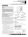
Ignitor
Button
Control Knob
A WARNING: You must operate this fireplace with
_
the screen in place. Make sure fireplace screen is
installed before running fireplace.
)
—
Figure 45- Control Knob In The OFF Position
NOTICE: During initial operation of new fireplace,
burning logs will give off a paper-burning smell. Open
window to vent smell. Operate f ireplace on HI position
to burn off odor. This will only last a few hours.
Electrode
7-Pilot
Burner
o
1.
STOP! Read the safety information above.
2.
Make sure equipment shutoff valve is fully open.
3.
Turn control knob clockwise /M k to the OFF position.
I
Ignitor
Electrode
Thermocouple
Pilot
Burner
11-- l 11:7
Figure 46 - Natural Gas Pilot Figure 47 -Propane/LP Gas Pilot
f
'07032.01J
Mar: 1111W , 1{ ;: a; visit www.desatech.com
CIDESA
OPERATING FIREPLACE (THERMOSTAT-CONTROLLED MODELS)
To Turn Gas Off To Appliance
Thermostat Control Operation
Manual Lighting Procedure
Operating Blower
OPERATING FIREPLACE (REMOTE-READY MODELS)
For Your Safety Read Before Lighting
OPERATING FIREPLACE
Continued
TO TURN OFF GAS
TO APPLIANCE
Shutting Off Fireplace
I. Turn control knob clockwise
to the OFF position.
2. Turn off all electric power to the appliance (if applicable)
if service is to be performed.
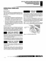
Shutting Off Burners Only (pilot stays lit)
Turn control knob clockwise r Thilk to the PILOT position.
THERMOSTAT CONTROL
OPERATION
Figure 48 - AUTO/OFF/ON Blower Switch
The thermostat used on this fireplace senses the room temperature. At times the room may exceed the set temperature. If so,
the burner will shut off. The burner will cycle back on when
room temperature drops below the set temperature.
REMOTE-READY MODELS
FOR YOUR SAFETY
READ BEFORE LIGHTING
The control knob can be set to any heat level between HI and LO.
Note: The thermostat sensing bulb measures the air near the
A WARNING; If you do not follow these instructions
fireplace cabinet. This may not always agree with room temperature (depending on housing construction, installation location, room size, open air temperatures, etc.). Frequent use of
your fireplace will let you determine your own comfort levels.
MANUAL LIGHTING
PROCEDURE
1.
Follow steps 1 through Sunder Lighting Instructions, page 23.
2.
With control knob pressed in, strike match. Hold match to
pilot until pilot lights.
3.
Keep control knob pressed in for 30 seconds after lighting
pilot. After 30 seconds, release control knob. Now follow
step 8 under Lighting Instructions, page 23.
exactly, a fire or explosion may result causing property damage, personal injury or loss of life.
A.
This appliance has a pilot which must he lighted by hand.
When lighting the pilot, follow these instructions exactly.
B.
BEFORE LIGHTING smell all around the appliance area
for gas. Be sure to smell next to the floor because some gas
is heavier than air and will settle on the floor.
WHAT TO 1)0 IF YOU SMELL GAS
• Do not try to light any appliance.
• Do not touch any electric switch; do not use any phone in
your building.
• Immediately call your gas supplier from a neighbor's
phone. Follow the gas supplier's instructions.
• If you cannot reach your gas supplier, call the tire department.
OPERATING
BLOWER
This blower has three settings: ON, OFF, and AUTO. In the ON
position, the blower will operate constantly. In the OFF position, the blower will not operate. In the AUTO position, the
blower will start when the thermostat senses a sufficient increase in firebox temperature.
Use only your hand to push in or turn the gas control knob.
Never use tools. If the knob will not push in or turn by
hand, don't try to repair it, call a qualified service technician or gas supplier. Force or attempted repair may result
in a tire or explosion.
C.
Note: Your fireplace and thermostat blower will not turn on D .
andofthesmi.Trplaceyunfosv
minutes before the blower turns on. After the heater modulates
to the pilot position, the blower will continue to run. The blower
w ill shut off after the firebox temperature decreases.
Do not use this appliance if any part has been under water.
Immediately call a qualified service technician to inspect
the appliance and to replace any part of the control system
and any gas control which has been under water.
Note: It is safe to operate fireplace with blower turned off.
However, the blower helps distribute heated air from the fireplace.
For more information,'
107032-011
OPERATING FIREPLACE (REMOTE-READY MODELS)
Lighting instructions
To Turn Off Gas To Appliance
Manual Lighting Procedure
OPERATING FIREPLACE
Continued
LIGHTING
INSTRUCTIONS
A WARNING: You must operate this fireplace with
the fireplace screen in place. Make sure fireplace
screen is installed before running fireplace.
NOTICE: During initial operation of new fireplace,
burning logs will give off a paper-burning smell. Open
window to vent smell. This will only last a few hours.
1.
STOP: Read the safety information in column 2, page 24.
2.
Make sure equipment shutoff valve is fully open.
3.
Set switch in the OFF position.
8. Keep control knob pressed in for 30 seconds after lighting
pilot. After 30 seconds, release control knob.
• If control knob does not pop out when released, contact
a qualified service person or gas supplier for repairs.
Note: If pilot goes out, repeat steps 4 through 8.
9.
Slightly push in and turn control knob counterclockwise
10.
Wait one minute and switch selector switch to the ON position to light burner.
11.
Set flame adjustment knob to any level between HI and LO.
to the ON position.
A CAUTION: Do not try to adjust heating levels by
using the equipment shutoff valve.
_
A WARNING: Make sure the selector switch is in the
!A
a WARNING: Burner will come on automatically
OFF position when you are away from home for long
periods of time. Fireplace will come on automatically
with selector switch in the ON position.
within one minute when the selector switch is in the
ON position after the pilot is lit.
to the
Pilot
Burner
•
Ignitor
Electrode
# ttr_
I g nitor
Pilot
•
Electrode
Burner
di., amp S,
*kw to,Nts .
4.
Press in and turn control knob clockwise
OFF position (see Figure 49).
5.
Wait five (5) minutes to clear out any gas. Then smell for
gas, including near the floor. If you smell gas, STOP! Follow "B" in the safety information, column 2, page 24. If
you don't smell gas, go to the next step.
Figure50-Propane/LPGasPllot Figure 51 - Natural Gas Pilot
6.
Press in and turn control knob counterclockwise f r's
to the PILOT position. Press in control knob for five (5)
seconds (see Figure 49).
TO TURN OFF GAS
TO APPLIANCE
7.
Ili
Note: You may be running this fireplace for the first time
Shutting Off Fireplace
after hooking up to gas supply. If so, the control knob may
need to be pressed in for 30 seconds or less. This will allow
air to bleed from the gas system.
1. Turn control knob clockwise 7-
With control knob pressed in, press and release ignitor button. This will light pilot. The pilot is attached to the front
burner. If needed, keep pressing ignitor button until pilot lights.
Note: If pilot does not stay lit, contact a qualified service
person or gas supplier for repairs. Until repairs are made,
light pilot with match. To light pilot with match, see Manual
Selector Switch in
OFF Position
Control Knob
(0) >gi
to the OFF position.
Set selector switch in the OFF position.
2b.
If Using Optional Hand - Held Remote: Set selector switch
in the OFF position to prevent draining battery.
Shutting Off Burners Only (pilot stays lit)
You may shut off the burners and keep the pilot lit by doing one
of the following:
Turn control knob clockwise /Th to the PILOT position.
2.
Use remote control manual OFF button.
3.
Set selector switch in the OFF position.
MANUAL LIGHTING
PROCEDURE
V
Au T c,
11
2a.
1.
Lighting Procedure.
•
1.
Follow steps 1 through 6 under Lighting Instructions.
2.
Depress control knob and light pilot with match.
3.
Figure 49-Control Knob and Ignitor Button Location (Shown as
Keep control knob pressed in for 30 seconds after lighting
pilot. After 30 seconds, release control knob. Now follow
Supplied - No Control Options)
steps 9 through 11, Lighlinb Instructions.
Ignitor Button
Flame Adjustment Knob
Lulu soot y visit www.desatech.com
-
107032-0 ri
MESA
OPERATING FIREPLACE (REMOTE-READY MODELS)
Optional Hand-Held Remote Operation
OPERATING FIREPLACE
Continued
THERMOSTAT SERIES (MODEL GHRCTB)
OPTIONAL HAND-HELD
REMOTE OPERATION
Note: All remote control accessories must be purchased separately (see Accessories, pages 38 and 39). Follow instructions
included with the remote control.
NOTICE: You must light the pilot before using
hand-held remote control unit. See Lighting Instructions on page 25.
1. After lighting, let pilot flame burn for about one minute.
Turn control knob to ON position. Adjust flame adjustment
knob anywhere between HI and LO. Slide the selector switch
to the REMOTE position (see Figure 52). Note: The burner
may light if hand-held remote was on when selector switch
was last turned off. You can now turn the burner on and off
with the hand-held remote control unit.
IMPORTANT: Do not leave the selector switch in the REMOTE or ON position when the pilot is not lit. This will
drain the battery.
Selector Switch H REMOTE Position
(Optional Hand-Held Remote Control) Control Knob
r0
0
Flame
, Adjustment
I Knob
71
Figure 52- Setting the Selector Switch, Control Knob, and Flame
Adjustment Knob for Hand-Held Remote Operation
ON/OFF SERIES (MODEL GHRCB)
Dold the control button on the hand-held remote until burner
turns on. Hold the control button again until burner turns off
(see Figure 53).
TO LOCK press both buttons on hand-held remote control until
light stops flashing. Hand-held remote control is now locked. If
the fire is on it will be turned off automatically. In the locked
state, the light will not light up when any button is pressed.
The hand-held remote can be operated using either the manual
mode (MANU) or thermostatic mode (AUTO) (see Figure 54).
To select Fahrenheit/Centigrade mode display, carefully press
the 'CIF mode button with the end of a paper clip or similar
blunt object.
Manual Mode
1.
2.
3.
Press the POWER and LOCK buttons together to turn on
the hand-held remote control.
Press the MANU button to turn on the fireplace.
Press the POWER and LOCK buttons together to turn off
the fireplace.
Auto (Thermostatic) Mode
1.
2.
3.
4.
Press the POWER and LOCK buttons together to turn on
the hand-held remote control.
Press AUTO button to select this mode.
Set the desired room temperature by pressing the TEMP
+ or - buttons.
Press the POWER and LOCK buttons together to turn off
the fireplace
Note: Do not leave the hand-held remote in the AUTO mode
close to the fireplace. The radiant heat from the fireplace will
turn if the fireplace. Ideally, place the hand-held remote in the
center of the room facing towards the fireplace.
Note: Do not hold the hand-held remote for a long time. Body
temperature will affect its operation in the AUTO mode.
Digital Displa
Shows
Temperature
Settings
Turns Burne
On or Off
Decreases F
Temperature
AUTO Mode
TO UNLOCK press both buttons together on hand-held remote
control until the light stops flashing. The hand-held remote is
now unlocked.
Control Button
Turns Burners
On and Off
Figure 53
-
Turns Hand-Held
Remote On or Off
and Allows You to
Choose the Manual
Setting
Selects Auto
Setting
Increases Room
Temperature in
AUTO Mode
Locks System to
Prevent Accidental
Ignition
Figure 54 - Thermostat Hand-Held Remote Control Unit (GHRCTB)
On/Off Hand-Held Remote Control Unit (GHRCB)
For more information;
a i
107032-07J
OPERATING FIREPLACE (REMOTE-READY MODELS)
Optional Hand-Held Remote Operation (Cont.)
GWMT1 Wail Mounted Thermostat (Optional)
OIVMS2 Wall Mounted Switch (Optional)
Operating Blower
,
Y,
■
S5,,,,analatifilltairanIONSIMINNESSIS
OPERATING FIREPLACE
Continued
OPERATING
BLOWER
Safety Features
When away from home for an extended period of time or as a
child safety feature to prevent accidental ignition of the fireplace, the receiver ON/OFF/REMOTE switch should be in the
OFF position.
Auto Shutoff Feature
1.
If the average room temperature exceeds 82 degrees Fahrenheit (28 degrees Centigrade), the hand-held remote control will perform a safety override and shut the fireplace
off. This feature is not available in the MANU mode.
2.
The receiver continuously receives signals from the handheld remote to control the room temperature. If the handheld remote is misplaced, obstructed, or for any reason
cannot transmit to the receiver, the receiver will shut off
This blower has three settings: ON, OFF, and AUTO. In the ON
position, the blower will operate constantly. In the OFF position, the blower will not operate. In the AUTO position, the
blower will start when the thermostat senses a sufficient increase in firebox temperature.
Note: Your fireplace and thermostat blower will not turn on
and off at the same time. The fireplace may run for several
minutes before the blower turns on. After the heater modulates
to the pilot position, the blower will continue to run. The blower
will shut off after the firebox temperature decreases.
Note: It is safe to operate fireplace with blower turned off.
However, the blower helps distribute heated air from the fireplace.
the fireplace after 8 minutes.
Key Pad Lock Feature
This feature allows the user to lock/unlock the keypad on the
hand-held remote in the MANU or AUTO mode to prevent
inadvertent operation (i.e. children operating the hand-held remote control, etc.). The keypad is locked in either on or off. Press
the POWER and LOCK buttons together to turn the unit on or off.
AUTO/OFF/ON
Sulch
"Mt,* frok t
.44X-Sign.
%WA
Ali,
.tit
GWMT1 WALL MOUNTED
THERMOSTAT (OPTIONAL)
Make sure the heater switch is on AUTO and set the temperature
adjustment on wall thermostat to the desired setting. The thermostat has been electronically calibrated at the factory and
requires no adjustment or leveling.
Figure 55 - AUTO/OFF/ON Slower Switch
Upon installation, the thermostat must be allowed to stabilize at
room temperature for a minimum of 30 minutes for proper
operation. See installation instructions on page 21 of this manual.
GWMS2 WALL MOUNTED
SWITCH (OPTIONAL)
Make sure the heater switch is on AUTO. This wall switch works
just like the conventional light switch. Flip the switch up for on
and down for off.
Note: Make sure that this switch is not in a position to be
mistaken for alight switch. This may result in the fireplace being
inadvertently turned on without the proper precautions being
taken. See installation instructions on page 22 of this manual.
JJ-1 =) -ea
107032-01J
:11444_ z.,
Gni visit www.desatech.com
MESA
INSPECTING BURNERS
Pilot Flame Pattern
Burner Flame Pattern
INSPECTING BURNERS
Check pilot flame pattern and burner flame patterns often
BURNER FLAME PATTERN
PILOT FLAME PATTERN
Figure 5S shows a correct burner flame pattern. Figure 59 shows an
incorrect burner flame pattern. The incorrect burner flame pattern
shows sporadic. irregular flame tipping. The flame should not be
dark or have an orange/reddish tinge.
Figure 56 shows a correct pilot flame pattern. Figure 57 shows an
incorrect pilot flame pattern. The incorrect pilot flame is not
touching the thermocouple. This will cause the thermocouple to
cool. When the thermocouple cools, the fireplace will shut down.
Note: When using the fireplace the first time, the flame will be
orange for approximately one hour until the log cures.
If pilot flame pattern is incorrect, as shown in Figure 57
•
•
turn fireplace off (see To Turn Off Gas to Appliance, page 24 for Thermostat-Controlled Models or page 25 for Remote-Ready Models)
If burner flame pattern is incorrect, as shown in Figure 59
•
turn fireplace otl(see To TW710ffGas to Appliance, page 24 for Thermostat-Controlled Models or page 25 for Remote-Ready Models)
•
see Troubleshooting, pages 30 through 32
see Troubleshooting, pages 30 through 32
Note: The pilot flame on natural gas units will have a slight curve,
but flame should be blue and have no yellow or orange color.
26,000 Btu/Hr Units
10,000 Btu/Hr Units
l
ir 1
a..L..siaiesi
--
Figure 58- Correct Burner Flame Pattern
26,000 Stu/Hr Units
Thermocouple
Figure 56 - Correct Pilot Flame Pattern (Propane/LP RemoteReady Shown)
10,000 Btu/Hr Units
we>
vsPa•4
I er
so
.s.r.
imik.
24
111/L111.1110,
)
lTt
Figure 59 - Incorrect Burner Flame Pattern
Thermocouple
Figure 57- Incorrect Pilot Flame Pattern (Propane/LP RemoteReady Shown)
For more informationt'
4.1 r
r - IJJJJ
107032-0IJ
CLEANING AND MAINTENANCE
Cleaning Burner injector Holder and Pilot Al, inlet Hole
Log Set
Cabinet
WIRING DIAGRAM
CLEANING AND
MAINTENANCE
Iniector Holder
A WARNING: Turn off fireplace and let cool before
Ports/Slot:
cleaning.
A CAUTION: You must keep control areas, burner,
and circulating air passageways of fireplace clean.
Inspect these areas of fireplace before each use. Have
fireplace inspected yearly by a qualified service person. Fireplace may need more frequent cleaning due
to excessive lint from carpeting, pet hair, bedding
material, etc.
Burner
Tube
Priman
Holes
Figure 60 - Injector Holder On Outlet Burner Tube
Pilot Air Inlet Hole
Pilot Air Inlet Hole
A
WARNING: Failure to keep the primary air
opening(s) of the burner(s) clean may result in sooting and property damage.
2
.■
0 V
CLEANING BURNER INJECTOR HOLDER
AND PILOT AIR INLET HOLE
The primary air in:etl ales allow the proper amount of air to mix with
the gas. This provides a clean burning flame. Keep these holes clear
of dust, dirt, lint, and pet hair. Clean these air inlet holes prior to each
heating season. Blocked air holes will create soot. We recommend
that you clean the unit every three months during operation and have
fireplace inspected yearly by a qualified service person.
We also recommend that you keep the burner tube and pilot assembly
clean and free of dust and dirt To clean these parts we recomme.nd using
compressed air no greater than 30 PSI. Your local computer store,
hardware store, or home center may carry compressed air in a can. You
can use a vacuum cleaner in the blow position. If using compressed air
in a can, please follow the directions on the can. If you don't follow
directions on the can, you could damage the pilot assembly.
1. Shut off the unit, including the pilot. Al low the unit to cool for
at least thirty minutes.
2. Inspect burner, pilot, and primary air inlet holes on injector
holder for dust and dirt (see Figure 60).
3.
4.
5.
6.
Blow air through the ports/slots and holes in the burner.
Check the injector holder located at the end of the burner tube
again. Remove any large particles of dust, dirt, lint, or pet hair
with a soft cloth or vacuum cleaner nozzle.
Blow air into the primary air holes on the injector holder.
—7
18/
Figure 61 - Pilot Inlet Air Hole
(Propane/LP Gas)
;D.? InDst
107032-01J
fijAy
=
Figure 62-Pilot Inlet Air Hole
(Natural Gas)
LOG SET
If you remove one-piece log set for cleaning, refer to Installing
Log Set and Screen, page 22, for placement instructions.
Replace log set if broken or chipped (dime-sized or larger),
CABINET
Air Passageways
• Use a vacuum cleaner or pressurized air to clean.
Exterior
• Use a soft cloth dampened with a mild soap and water mixture.
Wipe the cabinet to remove dust.
WIRING DIAGRAM
(Remote-Ready Models Only)
Auto I
Off I Switch
In case any large clumps of dust have now been pushed into
the burner repeat steps 3 and 4.
Clean the pilot assembly also. A yellow tip on the pilot flame
indicates dust and dirt in the pilot assembly. There is a small pilot
air inlet hole about two inches from where the pi let flame comes out
of the pilot assembly (see Figures 61 or 62 depending on model).
With the unit off, lightly blow air through the air inlet hole. You may
blow through a drinking straw if compressed air is not available.
Assembly
Pilot Assembly
TPTH
TH
Gas Control
TPTH TP
Red
Thermopile
.
visit www.desatech.com
CIIESA
TROUBLESHOOTING
1SOMPOW.4$140, ,,,
,
TROUBLESHOOTING
Note: For additional help, visit DESA
Heating Products' technical service web
site at www.desatech.com .
Note: All troubleshooting items are listed in
order of operation.
A WARNING: Turn off and unplug
A CAUTION: Never use a wire,
fireplace and let cool before servicing. Only a qualified service person
should service and repair fireplace.
needle, or similar objectto clean
ODS/pilot. This can damage
ODS/pilot unit.
OBSERVED PROBLEM
POSSIBLE CAUSE
REMEDY
When ignitor button is pressed, there is no
spark at ODS/pilot
I. Ignitor electrode not connected to ignitor cable
2. Ignitor cable pinched if V. et
I. Reconnect ignitor cable
3.
4.
5.
6.
Broken ignitor cable
Bad piezo ignitor
Ignitor electrode positioned wrong
Ignitor electrode broken
2. Free ignitor cable if pinched by any
3.
4.
5.
6.
metal or tubing. Keep ignitor cable dry
Replace ignitor cable
Replace piezo ignitor
Replace pilot assembly
Replace pilot assembly
Tum on gas supply or open equipment
shutoff valve
Turn control knob to PILOT position
Press in control knob while in PILOT
position
Continue holding down control knob.
Repeat igniting operation until air is
removed
Contact local propane/LP gas company
Clean °DS/pilot (see Cleaning and
Maintenance. page 29) or replace ODS/
pilot assembly
Replace gas regulator
When ignitor hunon is pressed, there is
1. Gas supply turned off or equipment
spark at ODS/pilot but no ignition
shutoff valve closed
2. Control knob not in PILOT position
3. Control knob not pressed in while in
PILOT position
4. Air in gas lines when installed
4.
5. Depleted gas supply (propane/LP only)
6. ODS/pilot is clogged
5.
6.
7. Gas regulator setting is not correct
7.
I. Control knob not fully pressed in
2. Control knob not pressed in long enough
I. Press in control knob fully
2. After ODS/pilot lights, keep control
knob pressed in 30 seconds
3. Wait one minute for safety interlock system to reset. Repeat ignition operation
01)5/pilot lights but flame goes out when
control knob is released
3. Safety interlock system has been
triggered
4. Equipment shutoff valve not fully open
5. Pilot flame not touching thermocouple,
which allows thermocouple to cool.
causing pilot flame to go out. This problem could be caused by one or both of
the following:
A) Low gas pressure
B1 Dirty or partially clogged °DS/pilot
6. Thermocouple connection loose at control valve
7. Thermocouple damaged
8. Control valve damaged
2.
3.
4. Fully open equipment shutoff valve
5. A) Contact local natural or propane/LP
gas company
B) Clean ODS/pilot (see Cleaning and
page 29) or replace ODS/
Maintenance,
pilot assembly
6. Dand tighten until snug, then tighten
1/4 turn more
7. Replace pilot assembly
8. Replace control valve
For more informationi r'i7 1-iii;d„.1,,J.„i„);;;IzJz JJ, 4.; .5 jj_u
0703P-01,1
TROUBLESHOOTING
TROUBLESHOOTING
Continued
OBSERVED PROBLEM
POSSIBLE CAUSE
Burner does not light after ODS/pilot is lit
1. Inlet gas pressure is too low
REMEDY
Contact local natural or propane/LP gas
2. Burner orifice is clogged
3. Thermopile leads disconnected or improperly connected (Remote-Ready
Models Only)
4 Burners will not come on in remote position (Remote-Ready Models Only)
Delayed ignition of burner
I. Clean burner (see Cleaning and Maintenance, page 29) or replace burner
orifice
2. Replace ciam4 d burner
3. Replace gas regulator
4. Contact local natural or propane/LP gas
company
I Burner orifice is clogged or damaged
2. Damaged burner
3. Gas regulator defective
4. Inlet vas pressure is too low
Slight smoke or odor during initial operation
1. Residues from manufacturing processes
and log curing
2. Not enough air
3. Gas regulator defective
Fireplace produces a whistling noise when
burner is lit
4. Replace battery in hand-held remote and
receiver
1. Contact local natural or propane/LP gas
company
2. Clean burner (see Cleaning and Maintenance, page 29) or replace burner orifice
1. Manifold pressure is too low
2. Burner orifice is clogged
Burner backfiring during combustion
company
2. Clean burner (see Cleaning and Maintenance, page 29) or replace burner orifice
3. Reconnect leads (see Wiring Diagram,
page 29)
I. Problem will stop after a few hours of
operation
2. Check burner for dirt and debris. If
found, clean burner (see Cleaning and
Maintenance, page 29)
3. Replace gas regulator
I. Turning control knob to HI position
when burner is cold
2. Air in gas line
I. Turn control knob to LO position and
let warm up for a minute
2. Operate burner until air is removed from
line. Have gas line checked by local
3. Air passageways on fireplace blocked
3. Observe minimum installation clearances (see pages 9 through 11)
4. Clean burner (see Cleaning and Maintenance. page 29) or replace burner orifice
natural gas company
4.
White powder residue forming within burner
box or on adjacent walls or furniture
Dirty or partially clogged burner on
ice
I. When heated, vapors from furniture polish, wax, carpet cleaners. etc. may turn
into white powder residue
Moisture/condensation noticed on windows
47: J.?
107032-CI J
r_L?
I. Not enough combustion/ventilation air
I. Turn fireplace off when using furniture
polish, wax, carpet cleaners, or similar
products
1. Refer to Air for Combustion and Venti
lotion requirements (page 6)
sur?
- ell; visit wrvw.desatech.com
MESA
TROUBLESHOOTING
TROUBLESHOOTING
Continued
A WARNING: If you smell gas
• Shut off gas supply.
• Do not try to light any appliance.
• Do not touch any electrical switch; do not use any phone in your
building.
• Immediately call your gas supplier from a neighbor's phone. Follow the
gas supplier's instructions.
• If you cannot reach your gas supplier, call the fire department.
/MPORTANT:Operating fireplace where impurities in air exist may create odors. Cleaning
supplies, paint, paint remover, cigarette smoke, cements and glues, new carpet or textiles,
etc., create fumes. These fumes may mix with combustion air and create odors. These odors
will disappear over time.
OBSERVED PROBLEM
POSSIBLE CAUSE
REMEDY
Remote does not function (Remote-Ready
Models Only)
1. Battery is not install. Battery power is
low
I. Replace 9-volt batteries in receiver and
remote control
Fireplace produces a clicking/ticking noise
just after hurners are lit or shut off
1. Metal expanding while heating or contracting while cooling
I. This is common with most fireplaces. If
noise is excessive, contact qualified service person
Fireplace produces unwanted odors
1. Fireplace burning vapors from paint,
hair spray, glues, cleaners, chemicals,
new carpet. etc. (Sec IMPORTANT
statement above)
2. Low fuel supply' (propane/LP only)
1. Open window to ventilate room. Stop using odor causing products while fireplace is running
3. Gas leak. See Warning statement
at top of page
Fireplace shuts off in use (ODS operates)
I. Open window and/or door for ventilation
2. Contact local natural or propane/LP gas
company
3. Clean ODS/pilot (see Cleaning and
Maintenance, page 29)
I. Not enough fresh air is available
2. Low line pressure
3. ODS/pi lot is partially clogged
Gas odor even when control knob is in OFF
position
1. Gas leak. See Warning statement
1. Locate and correct all leaks (see Checking Gas Connections, pages 19 and 20)
2. Replace control valve
at top of page
2. Control valve defective
Gas odor during combustion
1. Foreign matter between control valve
and burner
2. Gas leak. See Warning statement
at top of page
For more information $
2. Refill supply tank (propane/LP only)
3. Locate and correct all leaks (see Checking Gas Connections, pages 19 and 20)
I. Take apart gas tubing and remove foreign matter
2. Locate and correct all leaks (see Checking Gas Connections, pages 19 and 20)
1
107032-0IJ
SPECIFICATIONS
REPLACEMENT PARTS
SERVICE HINTS
TECHNICAL SERVICE
SPECIFICATIONS
Remote-Ready Models:
VMH26NRA, EFS26NR,
FMH26NR
Thermostat Models:
VMH1OTPB, EFS1OTP
Remote-Ready Models:
Thermostat Models:
VMH1OTNB, EFS1OTN VMH26PRA, EFS26PR,
FMH26PR
Btu/Hr
10,000
10,000
14.000/26,000
14,000/26,000
Type Gas
Propane/LP Gas Only
Natural Gas Only
Propane/LP Gas Only
Natural Gas Only
Ignition
Piezo
Piezo
Piezo
l'iezo
Manifold Pressure
8.5" W.F.
8" W.C.
3.5" W.C.
Inlet Gas Pressure
(in. of water)
Maximum
14"
Minimum*
11"
10.5"
4''
10.5"
11"
Dimensions, inches (lixWxD)
25 it /s x 26 " fit x 9 3/8
Fireplace
x 26
x 9 3/s
25 'Is x 26 " Is
25 7 /s x 26 13 /16 X 9 'R
25
32 78. X 27 13 /la x II cis
32 '/s x 27 13/16 x 11 5 /2
32 '4 x 27 L7
X
9 3/8
(including hood
and screws)
32
Carton
x 27 ' 3/16 x 11 Vg
11 'Is
Weight, pounds
7 2 lbs.
Fireplace
44 72 lbs.
44 Is lbs.
44 71 lbs.
44
Shipping
48 lbs.
48 lbs.
48 lbs.
48 lbs.
* For purpose of input adjustment
REPLACEMENT PARTS
SERVICE HINTS
Note: Use only original replacement parts. This will protect your
warranty coverage for parts replaced under warranty.
When Gas Pressure Is Too Low
•
pilot will not stay lit
PARTS UNDER WARRANTY
•
burners will have delayed ignition
•
fireplace will not produce specified heat
•
for propane/LP units. propane/LP gas supply may he low
Contact authorized dealers of this product. If they can't supply
original replacement part(s), call DESA Heating Products Technical Service Department at 1-866-672-6040.
You may feel your gas pressure is too low. If so, contact your local
natural or propane/LP gas supplier.
When calling DF.SA Heating Products, have ready
•
your name
•
your address
•
model and serial numbers of your fireplace
•
how fireplace was malfunctioning
•
type of gas used (propane/I.P or natural gas)
•
purchase date
TECHNICAL SERVICE
You may have further questions about installation, operation, or
troubleshooting. If so, contact DESA Heating Products' Technical
Service Department at 1-866-672-6040. When calling, please have
your 'node] and serial numbers of your heater ready.
Usually, we will ask you to return the part to the factory.
You can also visit DESA Heating Products' technical services well
site at www.desatech.com .
PARTS NOT UNDER WARRANTY
Contact authorized dealers of this product. If they can't supply original
replacement part(s). call DESA Heating Products at 1-866-672-6040
for referral information.
When calling DE:SA Heating Products, have ready
•
model number of your fireplace
•
the replacement part number
ly_Le
'07032.01J
s1SS35i'disiii
e eit
www.desatech.com
MESA
ILLUSTRATED PARTS BREAKDOWN
Models VMH1OTPB, VMH1OTNB, EFS1OTP and EFS1OTN
ILLUSTRATED PARTS
BREAKDOWN
THERMOSTAT-CONTROLLED MODELS
VMH1OTPB, VMH1OTNB,
.,..
EFS1OTP and EFS1OTN
s
—
1
..-----N---
C3
3
-2
32
" Tt
0"
14 .1 2; 24
20
25
23
42
A.)sk
/
4;
4
8
3••'\'
-„ 14 <1y 1
,
. . .. .
"-C- -. - :- .
„
n, ..
.,
—24
•tt
',,, ,----5k, 22
,,, s„..,
,,--- ,
21
?
et, 26
s
.,
,
1
30
I
For more information'
- Aiedr -,pd ±.,i,:cd.:f.IJL::JJJJ
107032-01J
PARTS LIST
Models VMH1OTPB, VMMOTNES, EFS1OTP and EFS1OTN
mansirh,
PARTS LIST
THERMOSTAT-CONTROLLED MODELS
This list contains replaceable pans
used in your fireplace. When ordering parts , follow the instructions listed
under Replacement Parts on page 33
of this manual.
PART NUMBERS
KEY
NO.
VMH1OTPB
E FS1OTP
VMH1 OTNB
EFS1OTN
DESCRIPTION
1
2
3
4
5
6
7
8
9
10
11
12
13
14
15
16
17
18
19
20
21
22
23
24
25
26
27
28
29
30
31
32
33
34
35
36
37
38
39
40
41
42
43
102633-02
102624-02
099230-02
098304-01
103591-02
103209-01
102635-02
M11084-26
103209-01
104281-01CK
102638-01
104286-01
—
099211-01
103963-01
103671-01
100587-01
098303-02
104335-01CK
102649-02
099415-04
102875-01
101381-01
099387-03
098271-10
M11084-38
101004-13
098522-27
102639-01
101628-01
102869-01
102731-01
103295-01CK
107153-01
104313-01
104313-02
M10908-2
103734-01
101006-01
097809-03
098249-01
101629-02
—
102633-02
102624-02
099230-02
098304-01
109824-04
103209-01
102635-02
M11084-26
103209-01
104281-01CK
102638-01
104285-01
—
099211-01
103963-01
103671-01
100587-01
098303-02
104335-01CK
102649-02
099415-10
102875-01
101381-01
099387-03
098271-10
M11084-38
101004-12
098522-27
102639-01
101628-01
102869-01
102731-01
103295-010K
107153-01
104313-01
104313-02
M10908-2
103734-01
101006-01
097809-03
098249-01
101629-02
107634-03
Outer Casing Top
Outer Casing
Shoulder Screw
Screw, #10 x 3/8 1'
Burner
Louvered Door
Left and Right Side Front
Hex Head Screw, #10 x 3/8''
Brass Top Louver
Firebox Hood
Firebox Top
ODS/Pilot Assembly
Firebox Wrapper
Control Bracket Screw
Inlet Tube
Outlet Tube
Brass Screw, #6 x 3/8
Regulator Screw
Outer Shell Base
Branch Support
Gas Regulator
Regulator Bracket
Valve Cover and Piezo
Pilot Tube
Ignitor Cable
Screw 48 x 3/8
Injector
Gas Valve
Baffle
Flexible Connector
Control Bracket
Control Shield
Screen Assembly
Log Set
Hinge Pin (Right)
Hinge Pin (Left)
Hinge Screws
Burner Support
Pilot Bracket
3/8" NPT x 3/8" Flare Brass Filling
Nut, M5
Bushing
NG Conversion Plate
QTY.
1
1
14
16
1
1
2
31
1
1
1
1
1
2
1
1
4
2
1
1
1
1
1
1
1
1
1
1
1
1
1
1
1
1
1
1
4
2
1
1
2
1
1
PARTS AVAILABLE — NOT SHOWN
101054-01
100563-01
103470-01
101054-01
100563-01
103470-01
Lighting Instructions Plate
Warning Plate
Hardware Package
1
1
1
" Part not available for field replacement.
z).?
707032-01J
— trik,r4ijk •
at. visit www.desatech.com
CIPESA
ILLUSTRATED PARTS BREAKDOWN
Modals VMH26PRA, VAIN26NRA, EFS26PR, and EFS26NR
ILLUSTRATED PARTS
BREAKDOWN
REMOTE-READY MODELS
VMH26PRA, VMH26NRA (Shown),
EFS26PR, EFS26NR
4 12
\
15
.
"
S
- ..---
AI
i
I
11
-ea,
ae,.."•
.....fr22
1
int-11%0.4r
9,
(14
3
:0
'
%
7.tt
% 1‘1
i
I
0
"-----...
,‘.
27
..
..... .. ... „„. .. .. .... .. ........
.-0
,
3218
*11....tt,;i1Mg
36
‘.
40
--
31
Z.
33 ---- 70;,..
- \\
G>
-12
24
.... , V ' .ty., 20
1 41 1 itilip:
M\
.
.
1
4
.i.f„ ,
-
14
.,
c.....,
..1.-...\--.>„
,
---c--...--_--- \--'.
6
, 3-:1„9.,. ,
5
.
30
:,/
I
21
11
/
,
28
i;V,;;IC
,.
-
..
For more informatioricnrte
1
07032 0,J
PARTS LIST
Models VMH26PRA, VMH26NRA, EFS26PR, and EFS26NR
-
,4iwzomeardivonsiait.
PARTS LIST
_
REMOTE-READY MODELS
This list contains replaceable
parts used in your fireplace.
When ordering parts, follow the
instructions listed under Replacement Paris on page 33 of
this manual.
_
KEY
NO.
1
2
3
4
5
6
7
8
9
10
11
12
13
14
15
16
17
18
19
20
21
22
23
24
25
26
27
28
29
30
31
32
33
34
35
36
37
38
39
40
41
42
43
44
PART NUMBERS
VMH26PRA
VMH26NRA
EFS26PR
EFS26NR
DESCRIPTION
102633-02
102624-02
099230-02
098304-01
109824-05
103209-01
102635-02
103209-01
104281-02CK
102638-01
103778-01
**
104322-01
104335-01CK
102649-02
102445-01
—
098271-10
107186-01
M11084-26
098249-01
103781-02
102639-01
101628-01
104305-01
103295-030K
107153-01
104313-01
104313-02
M10908-2
103734-01
101006-02
097809-02
101629-01
101629-02
M12461-26
103587-02
099998-01
098264-02
103284-03
—
099387-13
—
M10908-75
Outer Casing Top
,
Outer Casing
Shoulder Screw
Screw, #10 x 3/8"
Burner
Louvered Door
Lett and Right Side Front
Brass Top Louver
Firebox Hood
Firebox Top
ODS/Pilot Assembly
Firebox Wrapper
Burner Tube
Outer Shell Base
Branch Support
Piezo Ignitor
Regulator, Pilot
Ignitor Cable
Injector
Screw, Hex Head, #10 x 3/8
Nut, M5
Gas Valve
Baffle
Flexible Connector
Control Shield
Screen Assembly
Log Set Assembly Kit
Right Hinge
Lett Hinge
Hinge Screws
Burner Support
Pilot Bracket
Connector, Male
Bushing
Bushing
Gas Valve Screws
Plate, Switch
Switch, Fan
Connector, Male
Wire Harness
Pilot Tube to Regulator
Pilot Tube to Control Valve
NO Conversion Plate
Hex Wsr Head Tapping Screw
102633-02
102624-02
099230-02
098304-01
109824-05
103209-01
102635-02
103209-01
104281-020K
102638-01
103779-01
—
104322-01
104335-01CK
102649-02
102445-01
099918-02
098271-10
107186-02
M11084-26
098249-01
103781-01
102639-01
101628-01
104305-01
103295-030K
107153-01
104313-01
104313-02
M10908-2
103734-01
101006-02
097809-02
101629-01
101629-02
M12461-26
103587-02
099998-01
098264-02
103284-03
099387-14
099387-15
107634-02
M10908-75
CITY.
1
1
14
17
1
1
2
1
1
1
1
1
1
1
1
1
1
1
1
25
6
1
1
1
1
1
1
1
1
4
2
1
1
1
1
4
1
1
1
1
1
1
1
1
PARTS AVAILABLE —NOT SHOWN
_
103877-01
100563-01
103470-02
--
103877-01
100563-01
103470-02
-
Lighting Instructions Plate
Warning Plate
Hardware Package
1
1
1
Fart not avaliaore tor tiera replacement.
1,114.07
107032-Old
:ii
on, visit www.desatech.com
MESA
ACCESSORIES
ACCESSORIES
NOTICE: All accessories may not be available for all
fireplace models.
Purchase these fireplace accessories from your local dealer. If
they can not supply these accessories, call DESA Heating Products at 1-866-672-6040 for referral information. You can also
write to the address listed on the back page of this manual.
EQUIPMENT SHUTOFF VALVE - GA5010
For all models. Equipment shutoff valve with 1/8'' NPT tap. Fits
1/2" NPT pipe.
CABINET MANTEL WITH BUILT-IN HEARTH
BASE AND ROUNDED LEG STYLING
GMC61U Series - Unfinished
GMC6OF Series - Oak Finished
GMC65W Series - White Lacquer Finished
(Appearance May Differ by Model)
For all models. A mantel and hearth base offers compact styling and
completes the fireplace look. Available in an oak stained or an
unfinished birch, ready to stain or paint. Complete assembly instructions included. Three-sided brass trim kit included.
BRASS TRIM KIT - GA6095
For all models. Optional four-sided brass trim kit for recessed builtin installations (when unit is raised off of the floor). Provides a finished
appearance by covering rough edges of wall opening.
BRASS TRIM KIT - GA6094
(Not Shown)
For all models. Optional three-sided brass trim kit for custom and
recessed installations (when unit is on the floor). Provides a finished
appearance by covering rough edges of wall opening. Included with
all mantels
CORNER MANTEL WITH FULL HEARTH
BASE
GMC63U Series - Unfinished
GMC64F Series - Finished
-
THERMOSTAT-CONTROLLED BLOWER KIT
GA3450T
For all models. Space-saving mantel and hearth base corner design
features clean, classic lines. Available in a stained oak. w hue
lacquer or an unfinished hardwood, ready to stain or paint. Complete assembly instructions included. Three-sided brass trim kit
included.
For all models. Provides better heat distribution. Makes fireplace
more efficient. Automatically turns off and on as needed.
:0J .)..1.,:h.1:3 -3.1!,:t.-:;:ji,„r..;:t.).m
1070V-01J
ACCESSORIES
ACCESSORIES
Continued
RECEIVER AND HAND-HELD THERMOSTAT
REMOTE CONTROL KIT - GHRCTB
For all Remote-Ready Models. Allows the fireplace to be operated in
a manually or thermostatically controlled mode. You can turn the
fireplace on and off without ever leaving the comfort of your easy chair.
CABINET MANTEL AND FULL HEARTH BASE
GMC8OF Series - Oak Finished
GMC81U Series - Unfinished Birch
GMC82F Series - Cherry Finished Birch
For all models. Mantel features columns, moldings, fluting and
medallion. Dimensions (Wx14x1:0: 56" x 50" x 24"
RECEIVER AND HAND-HELD REMOTE
CONTROL KIT - GHRCB
CLEANING KIT - GCK
(Not Shown)
For all models. Your vent-free gas appliance requires regular
cleaning and maintenance to prevent performance problems. This
kit gives you the tools and instructions to make It easy to clean all
critical areas of your appliance.
WALL-MOUNT THERMOSTAT SWITCH
GWMT1
(Not Shown)
For all Remote-Ready Models. The desired comfort setting can be
selected on the wall thermostat and the fireplace will automatically
For all Remote-Ready Models. Allows the fireplace to be turned on
and off by using a hand-held remote control.
INFORMATION VIDEO - 108917-01
For all models. A care and maintenance video is available by
calling 1-866-672-6040. You may also email your request to
[email protected] .
FIRE CRACKLE - CF6A (Not Shown)
For all models. Creates the sound of a real burning fire.
cycle from pilot to the heat setting selected.
WALL MOUNT ON/OFF SWITCH
-
-
GWMS2
(Not Shown)
For all Remote-Ready Models. Allows the fireplace to be turned
on and off with a wall switch.
FirJ.11 JJJ;Jt-..:
IC( /U31-0 1J
MESA
NOTES
4110111111111110INSIMINAMSMCP=m1DW,
NOTES
For more informatioi4 1
107032-01)
OWNER'S REGISTRATION FORM
In order to provide better customer service for this and future purchases, we recommend that you register your product with us.
You can register online at www.desatech.com . If access to our website is not available to you, please complete this Owner's
Registration Form and mail to the address on the hack of this owner's manual. Please provide the following product information:
Brand:
(Comfort Glow, Vanguard, etc.)
Model:
(EFP33PR, VTGH33NR, etc.)
Date Purchased:
Note: Keep receipt for warranty verification.
Serial Number:
7 or 9 digit number located on product or identification tag.
First Name:
Last Name:
Address:
City:
Stale:
Home Phone:
Zip:
Country:
(
Please answer the following questions to register your product with DESA Heating Products:
I. Where will the product he used?
) Living/Family Hoom 9 Office/Warehouse 9 Utility Shed/Outbuilding 3 Garage 3 Bedroom 3 Bathroom 3 Other
2.
If you bought this product yourself, did you plan to purchase this type of product before going into the store? 9 Yes 'D No
3.
Who selected the product? 3 Male 0 Female a Both
4.
What is the population of your area? 0 Under 10,000 0 10,000 to 25,000 3 25,000 to 60,000 3 50,000 to 100,000
100,000 to 250,000 0 Over 250,000
S. What is your primary source of heat? 3 Propane (LP Gas) 0 Fuel Oil 9 Wood 3 Natural Gas 3 Electric 3 Other
6.
How was the product installed? 0 Professional Installer 0 Self 0 Other
7. Cost of product excluding sales tax? $
8.
Cost to install product? $
g. T )e of store where product was purchased? a Hardware 3 Propane Dealer 'D Natural Gas/Utility Co. 0 Home Center/Builder's Supply
0 Fifeplace or Hearth Shop 0 Farm Store 3 Other
10. What motivated you to buy this product? 3 Sudden Cold Weather ) Replace Older Model 3 D.I.Y. Home Project
:3 Emergency Back-Up Heat 3 Heater was on Sale 3 Energy Savings/High Efficiency
11.
. 3 Construction Project 0 Other
How did you learn about this product brand? 0 Advertising '3 Relative or Friend .3 Store Display .3 Other
12. Level of Education of Purchaser:0 Some High School 0 Completed High School 3 Completed College
13. Age of Purchaser: :3 Under 20
20 - 29 3 30 - 39 0 40 - 49 9 50 - 59 3 60 or Over
14. Buyer's total annual householdincome: '3 under 515,000
D 515,000 to 519,999
$20,000 to $34,999 3 $35,000 to $49,999
:3 550.000 to $74,999 0 $75,000 to $99,999 3 $100,000 and Over
15. Store where product was purchased:
Name:
City:
State:
16. In choosing this product, how important were the following:
Not Important
Somewhat Important
Availability
)
Price
Brand Name
)
Very Important
)
Overall Quality
Heat Output
Made in USA
Warranty
Local Service
Value for Price
9
Prier Brand Experience
Controls Location
Thermostat, Remote, or Manual Operation
Faso of Operation
Special Features
3
)
.3
)
)
3
3
Salesperson's Recommendation
)
Friend/Relative's Recommendation
)
Portability
Quiet Operation
Completed Graduate School
3
)
.3
3dV1
Postage
Required
CIIIIESAT.
HEATING PRODUCTS
2701 Industrial Drive
P.O. Box 90004
Bowling Green, KY 42102 - 9004
TAPE
WARRANTY INFORMATION
KEEP THIS WARRANTY
Model
Serial No.
Date Purchased
Always specify model and serial numbers when communicating with the factory.
We reserve the right to amend these specifications at any time without notice. The only warranty applicable is our standard written warranty. We make
no other warranty, expressed or implied.
LIMITED WARRANTY
VENT-FREE COMPACT CLASSIC HEARTH ® FIREPLACE
DESA Heating Products warrants this product to be free from defects in materials and components for four (4) years and five (5) years on stainless steel
hunters from the date of first purchase, provided that the product has been properly installed, operated and maintained in accordance with all applicable
instructions. To make a claim under this warranty the Bill of Sale or cancelled check must be presented.
This warranty is extended only to the original retail purchaser. This warranty covers the cost of part(sl required to restore this fireplace to proper
operating condition and an allowance for labor when provided by a DFSA Heating Products Authorized Service Center. Warranty part(s) MUST
be obtained through authorized dealers of this product and/or DESA Heating Products who will provide original factory replacement parts. Failure
to use original factory replacement parts voids this warranty. The fireplace MUST be installed by a qualified installer in accordance with all local
codes and instructions furnished with the unit.
This warranty does not apply to parts that arc not in original condition because of normal wear and tear, or parts that fail or become damaged as a result of
misuse. accidents, lack of proper maintenance or defects caused by improper installation. Travel, diagnostic cost, labor, transportation and any and all such
other costs related to repairing a defective fireplace will be the responsibility of the owner.
TO THE FULL EXTENT ALLOWED BY THE LAW OF THE IlJrasnicrioN TIIAT GOVERNS THE SALE OF THE PRODUCT; THIS
EXPRESS WARRANTY EXCLUDES ANY AND ALLOTHER EXPRESSED WARRANTIES AND LIMITS THE DURATION OF AC:1/ AND
ALL IMPLIED WARRANTIES, INCLUDING WARRANTIES OF MERCHANTABILITY AND FITNESS FOR A PARTICULAR PURPOSE
TO FOUR (4) YEARS ON ALL COMPONENTS AND FIVE (5) YEARS ON STAINLESS STEEL BURNERS FROM THE DATE OF FIRST
PURCHASE; ANDDFSA HEATING PRODUCTS' LIABILITY IS HEREBY LIMY] ED TOTHE PURCHASE PRICE OFTHE PRODUCT AND
DESA HEATING PRODUCTS SHALL NOT BE LIABLE FOR ANY OTHER DAMAGES WHATSOEVER INCLUDING INDIRECT,
INCIDENTAL OR CONSEQUENTIAL DAMAGES. •
Some states do not allow a limitation on how long an implied warranty lasts or an e ye1 u sion or l imitation of incidental or consequential damages,
so the above limitation on implied warranties, or exclusion or limitation on damages may not apply to you.
This warranty gives you specific legal rights, and you may also have other riahts that siar> from state to state.
For information about this warranty write:
0111ESA..
HEATING PRODUCTS
2701 Industrial Dove
P.O. Box 90004
Bowling Green, KY 42102 - 9004
WWW.desatech tom
,2 1 1 1 1
1111111 0111
107032-01
Rev. J
07/03
NOT A UPC
!.:TOLTI
NOTES
NOTES
' "r"rfrrAwigi.? inp.r",;
137032-013
gen, visit www.desatech.com
•ES/11
8/08/06
CESHIPPING
000213320
Bid*:
1
PO Number
30
5
-
Desa International
DESA (PARTS & ACCESSORIES)
SW063R
Page:
5:57:00
1 PL1
3_ 0 3 9 2 5 2
Customer Ship to... : 0801510 99999 TOM HINTON
HC62 BOX 30A
ALMA, WV 26320
• .U1A. . UPSCONSIGNEE
Order...:
E42216
11111MEMID11111111 1111 I
Home
Location
Need Qty
Part Number
Weight
INICHNIERMIMMMOMMMIMMAI
099387 14
....Description..*:
1
M52 064
040
1 -
Z00804
00 1
1 -
M93041
100
D10062
300
D10108
2.200
Z01403
000
TUBE, PILOT
099387 15
....Description..*: TUBE, PILOT
MHMUMMINHUMMMINMUMMMII
099918 02
....Description..*:
REGULATOR,
PILOT
11111111111111011 MUMMIIMMMAMI MINIM
1
103779 01
....Description..*: PILOT, O.D.S.
--
(NG)
AM HUI HAIM INIMMIIMMHMED
1
103781 01
....Description..*:
NERMIUMMEMMUMMI Ilil il il ilIl til
I/
1
107186 02
....Description..*:
'
VALVE, GAS
INJECTOR
Total
6
•
71(
2.641
00
5
8/08/06
CE SHIPPING
000213320
1
Bk#:
PO Number
-
Desa International
DESA (PARTS & ACCESSORIES)
SW063R
Page:
5:57:00
2 PL1
1_ 0 3 9 2 5 2
Customer Ship to...: 0801510 99999 TOM HINTON
HC62 BOX 30A
ALMA, WV 26320
• .U1A . . UPSCONSIGNEE
Order...:
Part Number
E42216
inummuniumm
Need Qty
Est Total Cube..:
...Order Comments
TRUCK LOAD MUST CALL TO MAKE A
DELIVERY APPOINTMENT
NJ PAUL 732-780-9340
PA RICK OR SCOTT 717-792-8750
VA MIKE 804-279-0203
NH RICK 603-679-4617
LTL MUST DELIVER B4 NOON
UPS ACCOUNT 4080314
LTL COLLECT SHIPMENTS MUST BE
CENTRAL TRANSPORT
ALL ORDERS SHIPPING FRT
COLLECT FROM CALIFORNIA WHS
MUST SHIP DOT-LINE
TRANSPORTATION
PH 800-423-3780
ALL ORDERS MUST BE PALLETIZED.
FAX/DC
C...Freight Collect
Home
Location
Weight
.000
INSTALLER: Leave this notice, the owner's manual and hang tags with the homeowner.
IMPORTANT HOMEOWNER
INFORMATION
NOTICE: The heater will produce smoke on initial firing. Open a window or door to the outside. The smoke
is from oils used in the manufacturing process and will go away after a few hours of operation.
Please read and follow instructions to prevent damage to your personal property.
1. Regularly inspect and clean your heater, Keep the burner, air inlet holes, and pilot clean. See your
owner's manual for cleaning and maintenance instructions.
2. For hearth products, make sure you properly locate logs on the grate. This is shown in your owner's
manual and on the hang tags. Flames should never touch any log (except for front flames of VS, VF,
CGG, VGX, CGX, LGX, EX, CTB, CSG, VRL, and NVS series glowing log sets, and VSGF28 and
CGFP28 series fireplace systems).
3. Soot can damage walls, curtains, carpets, and other personal property. While heater is "ON", the following can produce soot:
• Burning candles or oil lamps of any kind
• Burning incense
• Cigarette, cigar, or pipe smoke
• Incorrectly placed logs causing flame to contact logs
• Objects placed in or near the flames of your heater
• Burner air inlet or pilot burner dirty with dust, dirt, lint, or pet hair
• Running ceiling fans or other drafty conditions. This can disturb the normal flame patterns in
your heater
• Dirty flue and chimney (if your log set is in a vented masonry fireplace)
4. Your owner's manual contains detailed safety, operation, and cleaning instructions. Follow these instructions. Keep your owner's manual in a safe place. Refer to these instructions from time to time.
This information will help you keep your heater operating properly. You should have received an
owner's manual with your heater.
5. A care and maintenance video (part number 108917-01) for vent-free hearth products is available upon
request.
6. To receive the free video or information regarding the owner's manual, please call DESA Heating
Products' Customer Service Department at 1-866-672-6040. You can also visit our web site at
www.desatech.com .
• ESA,.
HEATING PRODUCTS
2701 Industrial Drive
P.O. Box 90004
Bowling Green, KY 42102-9004
www.desatech.com .
106898-01
Rev. E
03/03
•
-
-
—
"GIN
LE.51
alas-
sag
BE-C r.
a eft
p•
C
at
CC
0
.0
Srig
g
Sir&
2 302:
WI!
•2 -Eg
kEtt.las.*
_sant
POI
21_521
•
*Bps
4ibIg
-'
a ea
a 55
c
cs- Tz
cl
Ozzzac, zotoopl.
mc.- 1=0)4m
>-<nmuww
z_lopmzo
<,m o mcc<0
ww0
01 w..1
w > oozo
c
w er„ou. o u
zo
o
zz
o
< - ul u)
-J
4 Lu
4 0
C. la
Ct
z 2 W 214-214n
w$7.*Opza
afral< -PO
Xer. 2 ac
_oucCCiw
acu-Za m
ZOF 0
TIVecit0
s-Zrwano
/3 -• cc •- tu
02}20- tla
0° 31
CO
OM
0
EE:
at;
C7 C4.+
• o o .T.0..d6s2
asaaliau
0 mom fl
oc
ci
>a5
o ri ca:50. 15.
—
2
8
E
2. {0°C
ao a =
te-g
0
c
6
fle
0
a
• a .Ecamel
us
rcBcpt-ac
0--65g€
„t
P OOZijj
XDO
20/C 0 w
mcapo c e
20,w2D_
—
4
0
0
2
a
O 2 CD ec
eti c
2==.
.0.
,ct,=.
c ro cz0
cagEs=
280c(:24
cal;fl-owt
oNEepo
C
0
z
z
n
4 .... T.;
o
•- cam000c
Esc
E
-65
2-10
G5 it
tr
c
•a
0 a
• .
;.t. i
X i
c.P:A7
_ 2_ a=
_ _ a
$
le
F. 74 S.
, :s'
b-.
-_ t
a att:
- st
rt S
=.=---25.
..- -E =
=- •
=4
- s'
2
s" a=
,---, a ,
...-s• s:. 12
YQ. a .47,
r--;. S. E -=
E S
\
IF 7= :a
g
z
c
a.
- --...-
1
-
i
c .
't5;i
• Cir.-
15
fr.46 •
--o•
a
•4,
QS
=
_E„..... .-1.
52
sr s
itsa lt 2 s aa. l'.
65 7 3-, :7 7_ -! !.;_
=0 7_ 7 74
-
-3 :;'
a' •-.
11..
n •:-
•
9
so
k
t:-. se; Lt.
tirtill.01
'
7 -77.2
:1= 72
.,:._ c o l
_
,15 .2 :..
5 El
Oo 5. 5 a ii Z-.;
c'.
7
i.: -- tot
gBE C “ -12-.
:
c$*
.‘,.000000
-.et 's'.
• t
A
t
7; o-c 7. I
;„ r.- = a ,
1-1-7.=7
Tia.5
11
: ---•,_ .9.
7-= •-... I.
=
1.1.4
= a 7-4 ‘.• a =
=.7. -,E...==
=o
3 -2 2“ao-,..-4:1
7,
T. a 7 =" L,- ::.• 7 "--- 2- 7 ?. y -5-- =
'&2:1- :',
2 en-r-.70g=tA•4 2,-
3;4
PC C !
E
.51
-;S...
4 ..;
-6- 4 =
-7.:
5-=-•
f
= .
25
E-
c• =
---;
0
4
:5
0
10
4
ts.
u.
0
7
.-5a. sz:cetifs;--.5:-3
.E., g 0 E; 4E,:E.2,n-t
x,/s it 4E
ils.?•:"
a-
-2
fq=1=013±-i!si
0
.
l'atET;(2-72
l
'd -T:)
ja:1 6 1._"27 r="Sifl-67-LS -21! 2 71i. Eic
:I di `5.S '' 11= .2 >=A25.= :.:E
E FT* 7-go
Ez27,i..5.53T “ t5117-5
3
tre
;
E
:11-±"o'-'.:.ET- -7 '11.1-
si =gif. >4fl
4
G
23 v :m.
'PS
1.-
Ff
ta7
14-J
00
742=26--2-1
cco..-7.,
2/5 7.. 2 Ji;
,
c--c
fc-co
o
-
.
o
3
=
s5a.st;
r2-
=4 ,1
-
c.„_g 7 3
s
,
a't,ritm
17_.. 21cE
4 -74g2=
pE
-
=== .1-= 3 5
-'55c
1
7
..
r7-
•
,--,0 g_7 5
ar„.„
• eissa-2.
o
..„„aoao =Sat eu
= oat.=
-c 31 1_ 47)= .s
o z.:3 5 ZS
2 - trans
232,4"el
ess206,,:o
t a c cts.
-44 0 . o .=
u.
•••
Ztia.21 : p
E„.•;•43:
oc4.-3225 •
4• E r.! •-
I I.° use ti ;211
ELI