1
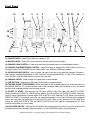
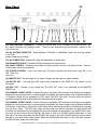
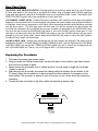
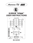
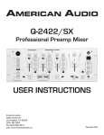
USER INSTRUCTIONS
Q-2422/SX Professional Preamp Mixer
Q-2422/SX
Featuring
Fader “Q” Start
Main Features
• 2 phono, 4 line, 2 auxiliaries & 2 mic inputs
• Fader "Q" On/Off switch • RCA and Balanced XLR Outputs
• High quality Alps Feather Fader™ for smooth, clean cross fading
• Bass, mid & treble control for mics • Volume control for each mic
• Fader "Q" Start* (fader allows auto return to preset digital cue points)
• On/Off Channel assign switch • Cue mixing slider • Split Cue monitoring
• Zone/Booth volume • Treble, Mid, and Bass control per a channel
• High level headphone output• On/Off/Talkover switch for DJ mic • Soft-touch
rubber knobs and fader handles for better control• Pan and Gain for
each channel • 12V BNC light connector for gooseneck light • Left & right
turntable ground connectors conveniently located on rear panel • Master
volume control • Master Level Indicators with peak hold • Left/Right master
balance• Cue Level Control • Cue button with LED for each channel
• Neutrik combo microphone connection 1/4”(6.3mm)/XLR • Independent
light control output for touch panels and chase controllers - 1/4"
connection • Convenient "L"-Shape design allows you to mount other units
directly against the mixer
The Q-2422/SX comes with a 2 year limited warranty!
* Compatible with American DJ CD Players also featuring Fader "Q" Start
© American DJ® AUDIO Los Angeles, CA 90058 USA
Specifications subject to change without notice.
©American
DJ Audio® - www.americandj.com - Q-2422/SX™ User Instructions page 2
Quick Start Instructions:
American DJ would like to thank for your purchase of this great product. For those of you that are to
impatiant to read the entire user manual we have compiled these quick start instructions. We
hope that you will at least read through
these instructions to familirize yourself
with the basic understanding of the unit.
The Q-2422/SX is part of American
DJ's countinuing eveolution in audio
technology. This unit has been built and
desinged with the typical DJ in mind,
by DJ's. We have attempted to provide
you with the most relable product on the
market by using only componedt made
from quility products.
Master Level - Use this level control to set your volume output. Try never to send an output of more
than +4dB to your sytem. Signal at levels higher than this will start to distord and may cause damage
to your system and speakers. Remeber that a distorded signal from you mixer will only be multiplied
throughout your system.
Channel Trim Level - The channel trim levels are not to be used as volume controls, never use the
channel trim to set the output volume. These controls are used to aid in distortion control. Use these
control to preset your signal level before the crossfader. With your channel faders in the maximum
position, use the channel trim level to set an average output level of about +4dB on you master level
meter.
Headphones - To avoid sever hearing damage alway be sure the headphone level is set to minimum
before plugging them in. Never put the headphone on without making sure the headphone level is
turned down.
Main Mic - The main mic connector uses a Nuetrik combo plug which allows you to connect either
a 1/4" unbalanced jack or by a standart 3-pin XLR balanced connector. The main mic also has an
indipendent volume control with seperate high and low level adjustments. When feedback occures
when using the mic, try lowering the "low" level this may reduce the feedback. Always leave the mic
level to it's minimum level when not in use.
PHONO/AUX/LINE SWITCH (5) - This switch is used to change the selected input from phono
to line and vice versa. Channels 1 and 2 may be switched PHONO/AUX or LINE. Channel 3
may be switched LINE 3 or LINE 4. The selectors for AUX1/PHONO1 and AUX2/PHONO2 are
on the rear panel (29).
©American
DJ Audio® - www.americandj.com - Q-2422/SX™ User Instructions page 3
Contents
• Safety Instructions...............................................................................................p.4
• Operating Determinations...................................................................................p.5
• Connections.......................................................................................................p.5
• Functions (Front Panel)....................................................................................p.6-7
• Inputs & Outputs (Rear Panel)..........................................................................p.7-8
• Replacing the Crossfader....................................................................................p.9
• Technical Specifications.....................................................................................p.10
• Warranty & Service............................................................................................p.10
Thank you for purchasing the Q-2422/SX™ by American DJ®. This unit is ready to be used, there Is no assembly required.
Please read the following Instructions before installing or using your new unit.
CAUTION! - Keep this device away from rain and moisture!
Safety Instructions
Always plug in the power last. Make sure that the Power switch is set to the OFF position before connecting other
devices to the mixer.
Keep away from heaters and other heating sources!
If the device has been exposed to drastic temperature fluctuation (e.g. after transportation), do not switch on the
mixer immediately. The arising condensation of water might damage your device. Leave the device switched off until
it has reached room temperature.
Never put any liquids on the mixer or close to it. Should any liquid enter the device, disconnect from main power
immediately. Have the device checked by a qualified service technician before operating again. Any damage caused by
liquid entering the device is not subject to warranty!
Never let the AC cord come in contact with other cables! Handle the AC cord and all AC connections with particular
care.
Make sure that the available voltage is not higher than stated on the AC voltage selector (26).
Before the device is switched on, all fader and volume controls should be set to 0 or minimum position.
Damages caused by manual modifications to the device or unauthorized operation by unqualified persons are not
subject to warranty.
There are no user serviceable parts inside the mixer. For maintenance and/or service, contact an authorized American
DJ® dealer.
©American
DJ Audio® - www.americandj.com - Q-2422/SX™ User Instructions page 4
Operating Determinations
When installing this mixer, please make sure that the device is not exposed to extreme heat, moisture or dust!
There should not be any cables lying around. Doing so endangers you as well as others. Do not operate the mixer
in extremely hot (more than 30° / 100°F) or extremely cold (less than 5°C / 40°F) surroundings. Keep away from
direct sunlight and heaters.
Operate the mixer only after becoming familiar with its functions. Do not permit operation by persons not qualified to
operate the mixer. Most damages are the result of unprofessional operation!
Never use spray cleaners to clean the faders! Never use solvents or abrasive detergents to clean the mixer! It is
recommended that you use a soft damp cloth. Please consider that unauthorized modifications on the device are
forbidden due to safety reasons!
Connections (Refer to diagrams on pages 6 & 8)
• Make sure that the POWER SWITCH (1) is set to OFF. Before connecting other devices to the mixer, all units have to
be switched off and the MASTER FADER (13) is set to 0.
• Make sure that the available voltage is not higher than stated on the voltage selector (26) before connecting to
power.
• In order to obtain the highest sound quality, only use high quality American DJ®, Ameri-Cable ™ cables for connecting
devices. Make sure that the cables are properly fixed.
• Connect your amplifier to the BALANCED OUTPUT JACKS (28) or the MASTER OUT JACKS (31). Make sure
that the channels are set properly.
• For recording, connect your tape recorder or cassette deck to the REC OUT JACKS (33). The REC OUT level will
not be influenced by the MASTER FADER (13).
• Connect your microphone to either the 1/4 inch (6.3mm) MIC 1 JACK (15) on the front panel, or the 1/4 inch
(6.3mm) MIC JACK 2 (38) on the rear panel. You can adjust the microphone volume output by turning the MIC
1 or 2 VOLUME (18) knobs. MIC 1 TREBLE, MID & BASS may be controlled by the MIC BASS, MID & TREBLE
KNOBS (19) above the TALKOVER switch.
• You can connect 2 turntables using the LEFT & RIGHT RCA PHONO 1 (35) AND PHONO 2 JACKS (35) on the rear
panel. You can only control the turntables signal after you have switched the PHONO /AUX SELECTOR SWITCH (36) on
the rear panel to PHONO, plus you must change the PHONO/AUX/LINE SWITCH (5) on the front panel to PHONO/AUX.
The signal is then controlled via the CH-1 AND CH-2 FADERS (6).
• Connect your tape player, tuner, sound effects, CD player, and cassette decks etc. to the LEFT & RIGHT RCA LINE
SIGNALS (34, 35, & 37) on the rear panel. The signal is then controlled via the CH-1, CH-2 AND CH-3 FADERS (6)
when the PHONO/AUX/LINE SWITCH on the front panel (5) is switched to LINE . CD players, cassette decks etc.
may also be connected to the LEFT & RIGHT RCA PHONO/AUX JACKS (35 & 37) on the rear of the unit. You can
only control this signal after you have switched the PHONO / AUX SELECTOR SWITCH (36) on the rear panel to
AUX, plus you must change the PHONO/AUX/LINE SWITCH (5) on the front panel to PHONO/AUX. The signal is then
controlled via the CH-1 AND CH-2 FADERS (6).
©American
DJ Audio® - www.americandj.com - Q-2422/SX™ User Instructions page 5
Front Panel
15
5
22
4
3
2
21
20 24
16
1
19
10
18
6
17
8
7
9
13 11
12
14
23
(1) POWER SWITCH - Red LED will light when power is ON.
(2) MASTER LEVEL - Dual LED's show the level of the left and right master output.
(3) CHANNEL GAIN CONTROL - Used to set the level of the output signal for its designated channel.
(4) CHANNEL BASS/MID/TREBLE CONTROL - Used to increase or decrease the LOW's, MID’s, and HI’s of
the output signal. The Q-2422/SX features "Rotary Kills" with -35dB to +15dB output control.
(5) PHONO/AUX/LINE SWITCH - Used to select the input to be sent to the individual channel. Channels 1
and 2 may be switched PHONO/AUX or LINE. Channel 3 may be switched LINE 3 or LINE 4. The selectors for
AUX1/PHONO1 and AUX2/PHONO2 are on the rear panel (36).
(6) CHANNEL FADER - Used to adjust the output level of each channel.
(7) CUE BUTTONS - Engage the CUE button to monitor the assigned channel.
(8) FEATHER FADER™ CROSSFADER - Mixes the signals of the assigned channels. To assign channels use
the ASSIGN SWITCH (17) located on either side of the crossfader. When the crossfader is set in the center
position, both assigned channels can be heard at once.
(9) ON/OFF “Q” START- Start and stop the CD Player with the slide of the fader. The ON/OFF “Q” START
switch activates this FADER “Q” START feature. When in the ON position, the FADER “Q” START allows the
signal to return automatically to preset digital CUE POINTS on your American DJ CD Player (also featuring
FADER “Q” START). For example, each time you slide the crossfader to far left, the CD Player will be triggered
to play the song from the beginning of the preset CUE POINT. Refer to your American DJ CD Player User
Manual for setting CUE POINTS. Turn the ON/OFF SWITCH to the OFF position to disengage the “Q” Start
function and resume to a normal fader.
(10) TALKOVER SWITCH - While in the ON position the microphone can be used at any time, while this will
not attenuate any other channels. When the switch is in the TALKOVER position, the microphone is
©American
DJ Audio® - www.americandj.com - Q-2422/SX™ User Instructions page 6
Front Panel Cont.
hot, meaning that when the microphone is in use all channels attenuate -15dB except the MIC. When the
microphone is not being spoken into all channels return to normal. In the OFF position, all signals return to
their original level and the microphone is off.
(11) CUE MIXING CONTROL - Mixes the signal to be monitored. The monitor signal comes from the Prefader.
This means it will not be affected by the channel faders. You can monitor each channel individually. Connect
your headphones to the HEADPHONES jack (14). Slide the CUE MIXING CONTROL (11) to CUE and select
the desired channels with the CUE switches (7). When you slide the CUE MIXING CONTROL to PGM (PFL
switches without function), you can cue the output signal of the mixer. If the CUE MIXING CONTROL is set
to the center position, you can cue both the channel signal you selected and the output signal. With the CUE
LEVEL control (12), you can adjust the phones volume without changing the output signal.
(12) CUE LEVEL CONTROL - This knob controls the headphone output volume.
(13) MASTER FADER - This slider control the master output volume.
(14) HEADPHONES JACKS - Use this jack to connect the headphones. Headphones from 8 Ohms to
600 Ohms can be used. 16 Ohms is recommended. The headphone input is conveniently located on the
face panel.
(15) MIC 1 JACK - You can connect microphones with a 1/4 inch (6.3mm) jack or XLR connector.
(16) BNC JACK FOR GOOSENECK LAMP - This jack is used to connect an American DJ 12V DC
gooseneck lamp.
(17) ASSIGN SWITCH - Used to select which channel is to be mixed with another.
(18) MIC 1 & 2 VOLUME CONTROL - Adjust the microphone volume of MIC 1 and MIC 2.
(19) MIC BASS, MID, AND TREBLE CONTROL - Use these controls to fine-tune the MIC 1 signal. Increase
the LOW’s by turning the MIC BASS CONTROL to the right, increase the MID’s by turning the MIC MID
CONTROL to the right, and increase the HIGH’s by turning the MIC TREBLE CONTROL to the right.
(20) SPLIT CUE - Control and monitor headphone signal. Slide fader to the left to hear the source music from
channel or channels selected by CUE BUTTONS (7). Slide fader to the right to hear PROGRAM MIX (PGM)
output. The smooth CUE MIXING fader is designed for fast and frequent headphone monitoring.
(21) MASTER BALANCE CONTROL - Used to adjust how much of the signal is sent to the left and right
MASTER OUT jack (31).
(22) PAN CONTROL - The balance control for each channel, or how much left and right signal for the specific
channel. There is a PAN CONTROL for each of the 3 channels.
(23) ZONE VOLUME, (24) ZONE BASS/TREBLE - Use ZONE VOLUME (23) and ZONE BASS & TREBLE
(24) knobs to control the output signal for the ZONE. (i.e. other rooms in a club, another amplifier, a satellite
speaker system, a microphone paging system or the DJ control booth monitors).
©American
DJ Audio® - www.americandj.com - Q-2422/SX™ User Instructions page 7
Rear Panel
26
25
27
28
29
30
31
32 33 34
35 36 37 36
38
(25) GND (GROUND TERMINALS) - Connect the ground lead of the turntables with these terminals. This
will reduce humming and popping noises. There are two convenient ground terminals located on the
rear of the mixer.
(26) AC VOLTAGE SELECTOR - Select between 115V/50Hz or 230V/60Hz. Make sure that the selector
is set to the
proper voltage you are using.
(27) AC CONNECTION - Standard IEC plug with detachable AC power cord.
(28) BALANCED OUTPUT - Balanced XLR-plug output for the master signal.
(29) LIGHT CONTROL - Buffered audio output for light controllers that can use external input. Great for
Touch Panels and Chase Controllers.
(30) PLAYER CONTROL - Input mini plugs from CD player controller into these jacks, input CD 1 into
jack 1 and CD 2
into jack 2.
(31) MASTER OUT - Parallel output of P.A. output. Connect with the input of a power amplifier.
(32) BOOTH OUT - Left and right RCA output jacks controlled by the ZONE (23, 24) controls on the
front panel.
(33) REC OUT - Connect to your record unit. The REC OUT level is not influenced by the MASTER
FADER (13).
(34) CHANNEL 3 INPUT JACKS - Connect CD players, tape decks, DAT machines, and all other non-magnetic
equipment to the line level inputs. Line level musical instruments with stereo outputs such as Rhythm Machines
or Samplers should also be connected to LINE inputs. The RCA input jacks are color code, the red jack
reprsents the right channel and the white jack represents the left channel.
(35) CHANNEL 2 INPUT JACKS - Connect CD players, tape decks, DAT machines, and all other non-magnetic
equipment to the line level inputs. Line level musical instruments with stereo outputs such as Rhythm Machines
or Samplers should also be connected to LINE inputs. When connecting turntables with MM pickup cartridge
use the Phono inputs. The RCA input jacks are color code, the red jack reprsents the right channel and
the white jack represents the left channel. Be sure your turntable are connected to the AUX/PHONO jacks,
you must also be sure that the AUX/PHONO (38) switch is set to the "PHONO" position. Never plus in a line
level input in to these jacks while the AUX/PHONO (38) switch is set to the "PHONO poistion, this may cause
damage to your mixer and/or audio system. When the AUX/PHONO (38) switch is set to the "AUX" position,
the jacks will only accept a line level input.
©American
DJ Audio® - www.americandj.com - Q-2422/SX™ User Instructions page 8
Rear Panel Cont.
(36) PHONO / AUX SELECTOR SWITCH - Changes phono to an extra line; allows the DJ to use a CD player
or other input device in the same line as the phono line. When using a turntable select PHONO, and when
using other input devices select AUX. PHONO/AUX lines can be used with LINES 1 and 2. The PHONO /AUX
SELECTOR SWITCH gives the DJ the possibilities of 2 extra input lines.
(37) CHANNEL 1 INPUT JACKS - Connect CD players, tape decks, DAT machines, and all other non-magnetic
equipment to the line level inputs. Line level musical instruments with stereo outputs such as Rhythm Machines
or Samplers should also be connected to LINE inputs. When connecting turntables with MM pickup cartridge
use the Phono inputs. The RCA input jacks are color code, the red jack reprsents the right channel and
the white jack represents the left channel. Be sure your turntable are connected to the AUX/PHONO jacks,
you must also be sure that the AUX/PHONO (38) switch is set to the "PHONO" position. Never plus in a line
level input in to these jacks while the AUX/PHONO (38) switch is set to the "PHONO poistion, this may cause
damage to your mixer and/or audio system. When the AUX/PHONO (38) switch is set to the "AUX" position,
the jacks will only accept a line level input.
(38) MIC 2 INPUT JACK - Connect your microphone with 1/4 inch (6.3mm) jack plug here. The signals may be
controlled by the MIC 1 VOLUME KNOB (18). BASS & TREBLE for MIC 1 can be adjusted by the MIC BASS
CONTROL KNOB (19) and the MIC TREBLE CONTROL KNOB (19). MIC 2 volume can be adjusted by the
MIC 2 VOLUME KNOB (18). There is also a XLR-plug for MIC 1 (15) on the front panel.
Replacing the Crossfader
1. Disconnect the mixers main power supply
2. Using a number two Phillips screw driver, unscrew the each of the stainless steel retain screws
that hold the crossfader in place.
3. Gently remove the crossfader from its seated position. You may need to wiggle the crossfader
slightly to remove it.
4. After removing the crossfader, disconnect the ribbon cable that attaches the crossfader to the
PC board. Grasp the crossfader by its base and pull the ribbon cable by its connector not the
actual cables. The connector is desired to only fit one way, so don't worry about the connectors
orientation.
5. Connect the new crossfader to the ribbon cable and replace in reverse order.
©American
DJ Audio® - www.americandj.com - Q-2422/SX™ User Instructions page 9
Technical Specifications - Model Q-2221/X
Model:
Q-2422/SX™, 2 Channel Mixer
Power supply:
AC 115/230V, 50/60Hz switchable
Dimensions:
19" W x 7" D x 2.25" H / 482x 176x 65mm
Weight:
8.5 lbs. / 3.8 kg
Crossfader:
FF-Plus - Optical detecting fader start control - Low grounding impedance crossfader
Power Consumption: 5W typical, 7W w/ full headphone output
Headphone impedance: 16 Ohms
Input Sensitivity (Level/Impedence):
Line: -14dBV (200mV) 12K Ohm +/- 2dB
Microphone: -49 dBV (3.6mV0 / 3K Ohms +/- 3 dB
Phono: -48dBV (4mV) 47K Ohms +/- 3dB
Aux: -14 dBV (200mV) / 47K Ohms +/- 2dB
Output Sensitivity (Level/Impedence):
Rec Out (RCA): -10dBV (316mV) / 2.2K Ohms +/- 2dB
Master Out (RCA): 0dBV (1V) / 610 Ohms +/-2dB
Phones (Load+32Ohms): -8dBV (0.4V) /33 Oms +/-2dB
Maximum Output (Load + 47K, THD = 5%)
Rec: < 18dBV (8V)
Master (RCA): < 18dBV (8V)
Blanced (XLR): < 18dBV (8V)
Channel Balance: Within 3dB
Frequency Response:
• Line: 20Hz - 20KHz, ± 1dB
• Phono: 20Hz - 20KHz, ± 1.5dB (RIAA)
• Aux: 20Hz - 20KHz, ± 1dB
• Microphone: 20Hz - 20KHz, +1,-3dB
THD - Total Harmonic Distortion (1Khz, 0dBV Output):
Master Output (Load = 47K Ohms): Less than 0.2%
Phono: (Load = 32K Ohms): Less than 0.5%
Channel Equalizer:
Bass = +12 ± 1dB, -22 ± 2 dB at 70KHz / Mid = +12 ± 1dB, -17 ± 2 dB at 1KHz / Treble = +13 ±
1dB, -27 ± 2 dB at 13KHz
Microphone Equalizer:
Bass = +12 ± 1dB, -12 ± 1 dB at 100KHz / Treble = +12 ± 1dB, -12 ± 1 dB at 10KHz
Warranty & Service:
The Q-2422/SX™ has a 2-year limited warranty. Please mail in warranty card as soon as possible to validate
your warranty.
©American
DJ Audio® - www.americandj.com - Q-2422/SX™ User Instructions page 10