1
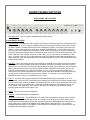
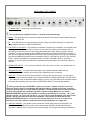
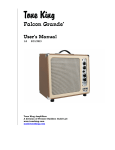
 TUBE GUITAR AMPLIFIER
MODEL: CHERRY BOMB
OWNER’S MANUAL
WELCOME TO HENNING AMPLIFICATION
Congratulations and thank you for choosing the Henning Cherry Bomb Guitar Amplifier!
At Henning Amplification, our mission is to design and build the finest tube guitar amplifiers for discerning
tone freaks. Hand built in the USA using the highest quality components and materials, our amplifiers sound
killer, look cool and are as durable and road ready as anything currently on the market.
The Cherry Bomb is a veritable “kitchen sink” of tone tools for gigging and recording musicians. It is a 100
watt tube amp that features two completely independent, footswitchable channels, each of which has
switchable gain modes and master volumes.
The PLEX channel is just what you might expect from the name and a lot more. With the channel’s
saturation switch in the center “off” position, you can get everything from sweet cleans to 60s/70s classic
rock tones. Set the gain up full in this channel and roll down your guitar’s volume and you’ll be blown away
by how the amp cleans up, even with higher output humbucking pickups. Another feature of the amp is the
channel jump switch, which simulates the external channel jumping commonly done with a certain late 60s
English guitar amp. Now play with the saturation switch. Moving it to the right adds a bit more gain and
compression putting you squarely in “Brown Sound” territory. Move the switch to the left and add even
more gain and compression. Now you’re in 80s hard rock/hair metal territory.
The ROD channel picks up where the PLEX channel leaves off adding another tube gain stage to get mean!
Eighties metal tones to more modern high gain metal tones are on tap here. Of course, you also get the
same 3-way saturation mode switch found on the PLEX channel, allowing tremendous flexibility in sculpting
YOUR ultimate tone. Singing lead tones and massive power chords can be dialed in when using the ROD
channel. The Cherry Bomb also features a footswitchable solo master volume in the ROD channel. You can
set it to provide a volume boost for live soloing and switch to that mode from either channel master.
The Cherry bomb also features global presence and density controls. Most guitarists are familiar with what a
presence control does (provides high frequency variable feedback in power amp section), but the density
control may be something they haven’t seen on an amp before. In simplest terms, it adds back low end
when the amp is played at low volumes. Turn up the Density control and you can still get the low end “feel”
of the amp at even “bedroom” volumes. Pretty cool, huh?
Of course, we didn’t stop there. The Cherry Bomb also features a footswitchable, tube-buffered effects loop
so you can add your time-based effects after the gain stages of the amp where they belong. You can
choose either series or parallel mode for the effects loop, affording you the ultimate flexibility in how you
want to use pedal or rack mount effects. For folks who run their effects in stereo or wet/dry/wet with
additional power amps and cabs, the Cherry Bomb also has adjustable line out. Yup… we thought of
everything!
Finally, the amp also features another, overall master volume. We’re going to get a little techy on you here,
but bear with us, because this is one of the coolest features of the Cherry Bomb. This master volume is
actually a post-phase inverter master volume design (PPIMV). We feel that this design provides the best
tones you can get for lower volume playing. You’ll get great sounding tones with this master all the way
down to “bedroom volumes’. Crank the channel masters up and turn the overall master down to the volume
level you’d like to play at and you’ll see that the overall master also adds some perceived gain and
compression to the tone. Experiment with balancing different settings of the channel masters and overall
master to get the tone you’d like at the right volume for the room you’re playing in. Of course, cranking the
overall master up full takes it completely out of the circuit and you can just adjust the channel masters to
the appropriate volume.
While the amp has a lot of options and controls, getting familiar with the Cherry Bomb amplifier is easy, so
don’t be terribly surprised when you find yourself up and running in no time. It’s really easy to dial in great
tones in both channels and find your voice with it.
IMPORTANT SAFETY INSTRUCTIONS
This symbol warns the user of dangerous voltage levels localized within the enclosure.
unit.
This symbol advises the user to read all accompanying literature for safe operation of the
Read, retain, and follow all instructions. Heed all warnings.
Only connect the power supply cord to an earth grounded AC receptacle in accordance with the voltage
and frequency rating that you specified when ordering the amp.
WARNING: To prevent damage, fire or shock hazard, do not expose this unit to rain or moisture.
Unplug the power supply cord before cleaning the unit exterior (use a damp cloth only). Wait until the unit
is completely dry before reconnecting it to power.
Maintain at least 6 inches (15.25 cm) of unobstructed air space behind the unit to allow for proper
ventilation and cooling of the unit.
This product should be located away from heat sources such as radiators, heat registers, or other products
that produce heat.
This product may be equipped with a polarized plug or a grounding type plug. A polarized plug has two
blades with one wider than the other. A grounding type plug has two blades and a third grounding prong.
The wide blade or the third prong is provided for your safety. This is a safety feature. If you are unable to
insert the plug into the outlet, contact an electrician to replace your obsolete outlet. Do not defeat the
safety purpose of this plug.
Protect the power supply cord from being pinched or abraded.
This product should only be used with a cart or stand that is recommended by the manufacturer.
The power supply cord of this product should be unplugged from the outlet when left unused for a long
period of time, or during electrical storms.
This product should be serviced by qualified service personnel when: the power supply cord or the plug has
been damaged; or objects have fallen, or liquid has been spilled onto the product; or the product has been
exposed to rain; or the product does not appear to operate normally or exhibits a marked change in
performance; or the product has been dropped, or the enclosure damaged.
Do not drip or splash liquids, nor place liquid filled containers on the unit.
CAUTION: There are no user serviceable parts inside, refer servicing to qualified personnel only.
Henning Amplification amplifiers and loudspeaker systems are capable of producing very high sound
pressure levels, which may cause temporary or permanent hearing damage. Use care when setting and
adjusting volume levels during use.
Hazardous voltages may be present within the cabinet even when the power switch is off and the power
cord is connected. Therefore, disconnect the power cord from the rear panel power inlet before servicing.
The power inlet must remain readily operable.
CHERRY BOMB FUNCTIONS
FRONT PANEL, LEFT TO RIGHT
1. GUITAR INPUT – Plug your guitar, pedalboard or stompbox in here
PLEX CHANNEL SECTION
2. SATURATION – This saturation switch sets the gain style for the PLEX channel. It is a 3-way switch and
the center position is OFF, meaning no additional gain and compression is added. If the switch is set to
the RIGHT position, a subtle amount of gain and compression is added. If the switch is set to the LEFT
position, a higher level of gain and compression is added. PLEASE NOTE – in the PLEX channel, the
amount of gain and compression that is added in either position of the switch is much more subtle than
what you’ll experience using the switch in the ROD channel of the amp. The SATURATION switch in the
PLEX channel is more of a “feel” thing than a “hear” thing, so if you don’t hear a lot of difference, don’t
worry, your amp is just fine. As you get used to the amp, you’ll certainly feel the difference between the
different settings. Also note that the effect of the SATURATION switch is much more noticeable at louder
overall volume settings.
3. MASTER – This is the master volume control for the PLEX channel. As you read in the previous section
you can use the channel masters along with the OVERALL MASTER on the back of the amp to get the
overall sound you want at the volume that is appropriate for the room you are playing in. We recommend
that you set the overall volume of the amp using the OVERALL MASTER on the back of the amp and
keep the channel masters fairly high (above halfway up or 12 o’clock) and use them to balance the
channels and solo volumes as needed. Of course, you can also set the OVERALL MASTER all the way
up and set your volumes with the channel and solo masters, it is really up to you. If the OVERALL
MASTER is all the way up, it is completely out of the circuit.
4. LOOP – The LOOP switch controls whether the tube-buffered effects loop is engaged or not. If the
LOOP switch is set to the LEFT, the effects loop is engaged and the BLUE LED next to the switch will be
lit. If the LOOP switch is set to the RIGHT, the effects loop is out of the circuit and the BLUE LED next to
the switch will not be lit. PLEASE NOTE – when the provided footswitch is connected to the amp, the
LOOP switch is not operational – the function of the switch is controlled by the footswitch instead,
including whether the BLUE LED lights or not.
5. BASS – Passive Low frequency equalization.
6. MIDDLE – Passive Mid frequency equalization.
7. INTERNAL PLEX JUMP – The INTERNAL PLEX JUMP switch simulates the external channel jumping
commonly done with certain late 60s English non-master volume guitar amp. On these amps, some
players like the tone they get by running a short phone plug jumper cable between the channels of the
amp to bridge them. When the INTERNAL PLEX JUMP switch is set to the LEFT, it is off and the
simulated channel jumping is not engaged. If the INTERNAL PLEX JUMP switch is set the RIGHT, the
simulated channel jumping is engaged.
8. TREBLE – Passive High frequency equalization.
9. GAIN – Sets the overdrive level of the PLEX channel.
10. CHANNEL SELECT - The CHANNEL SELECT switch controls whether the PLEX or the ROD channel is
engaged. If the CHANNEL SELECT switch is set to the LEFT, the ROD channel is engaged and the
YELLOW LED above the ROD channel GAIN control will be lit. If the CHANNEL SELECT switch is set to
the RIGHT, the PLEX channel is engaged and the GREEN LED above the PLEX channel GAIN control
will be lit. PLEASE NOTE – when the provided footswitch is connected to the amp, the CHANNEL
SELECT switch is not operational – the function of the switch is controlled by the footswitch instead,
including whether the GREEN or YELLOW LEDs light or not.
ROD CHANNEL SECTION
11. SATURATION – This saturation switch sets the gain style for the ROD channel when the SOLO master
volume is engaged. It is a 3-way switch and the center position is OFF, meaning no additional gain and
compression is added. If the switch is set to the RIGHT position, a subtle amount of gain and
compression is added. If the switch is set to the LEFT position, a higher level of gain and compression is
added. PLEASE NOTE – in the ROD channel, you will notice a significant volume reduction when the
SATURATION switch is set LEFT or RIGHT as compared to the OFF center position. This is normal and
no cause for concern. You’ll set this switch and adjust the SOLO master to get the volume you want.
Also note that the effect of the SATURATION switch is much more noticeable at louder overall volume
settings. We usually set this switch to the left for a higher gain, singing lead tone for the ROD channel
when the SOLO master volume is engaged.
12. SOLO – This is the SOLO master volume control for the ROD channel. It is only engaged when the ROD
channel is engaged AND the SOLO switch (see below) is set to the LEFT (or the footswitch is connected
and the SOLO footswitch is engaged) with the RED LED next to it lit. It is intended as a solo boost for
the ROD channel and overrides the regular channel master when engaged. You can set the associated
SATURATION switch for a lead tone and set SOLO so that it is a boost in volume over the regular
channel master. As you read in the previous section you can use the channel masters along with the
OVERALL MASTER on the back of the amp to get the overall sound you want at the volume that is
appropriate for the room you are playing in. We recommend that you set the overall volume of the amp
using the OVERALL MASTER on the back of the amp and keep the solo and channel masters fairly high
(above halfway up or 12 o’clock) and use them to balance the channels and solo volumes as needed. Of
course, you can also set the OVERALL MASTER all the way up and set your volumes with the channel
and solo masters, it is really up to you. If the OVERALL MASTER is all the way up, it is completely out of
the circuit.
13. SATURATION – This saturation switch sets the gain style for the ROD channel when the MASTER
master volume is engaged. It is a 3-way switch and the center position is OFF, meaning no additional
gain and compression is added. If the switch is set to the RIGHT position, a subtle amount of gain and
compression is added. If the switch is set to the LEFT position, a higher level of gain and compression is
added. PLEASE NOTE – in the ROD channel, you will notice a significant volume reduction when the
SATURATION switch is set LEFT or RIGHT as compared to the OFF center position. This is normal and
no cause for concern. You’ll set this switch and adjust the MASTER master to get the volume you want.
Also note that the effect of the SATURATION switch is much more noticeable at louder overall volume
settings. We usually set this switch OFF or to the right for a rhythm tone for the ROD channel when the
MASTER master volume is engaged.
14. MASTER – This is the MASTER master volume control for the ROD channel. It is only engaged when
the ROD channel is engaged AND the SOLO switch (see below) is set to the Right (or the footswitch is
connected and the SOLO footswitch is NOT engaged) with the RED LED next to it NOT lit. It is intended
as the main channel master volume for the ROD channel and overrides the regular channel master
when engaged. As you read in the previous section you can use the channel masters along with the
OVERALL MASTER on the back of the amp to get the overall sound you want at the volume that is
appropriate for the room you are playing in. We recommend that you set the overall volume of the amp
using the OVERALL MASTER on the back of the amp and keep the solo and channel masters fairly high
(above halfway up or 12 o’clock) and use them to balance the channels volumes as needed. Of course,
you can also set the OVERALL MASTER all the way up and set your volumes with the channel and solo
masters, it is really up to you. If the OVERALL MASTER is all the way up, it is completely out of the
circuit.
15. SOLO - The SOLO switch controls whether the SOLO master for the ROD channel (and associated
SATURATION switch) or the regular channel MASTER (and associated SATURATION switch) is
engaged. If the SOLO switch is set to the LEFT, the SOLO master for the ROD channel (and associated
SATURATION switch) is engaged and the RED LED next to the switch will be lit. If the SOLO switch is
set to the RIGHT, the regular channel MASTER (and associated SATURATION switch) is engaged and
the RED LED next to the switch will not be lit. PLEASE NOTE – when the provided footswitch is
connected to the amp, the SOLO switch is not operational – the function of the switch is controlled by the
footswitch instead, including whether the RED LED lights or not.
16. BASS – Passive Low frequency equalization.
17. MIDDLE – Passive Mid frequency equalization.
18. TREBLE – Passive High frequency equalization.
19. GAIN – Sets the overdrive level of the PLEX channel.
POWER AMP RESPONSE CONTROL SECTION
20. PRESENCE – High frequency variable feedback in power amp section.
21. DENSITY - Variable damping. Controls low frequency interaction between amplifier and speakers.
AC POWER / STANDBY
21. STANDBY - Turns on high voltage to output section.
22. ON/OFF – Switches main AC power on or off.
23. JEWEL LIGHT – The jewel light will be lit as soon as the ON/OFF switch is turned to the ON position.
REAR PANEL, LEFT TO RIGHT
1. AC MAINS INPUT – Connect to a grounded outlet.
Use only the factory supplied cord set or a UL approved equivalent type.
2. MAINS – This holds the mains fuse, which protects the amplifier from electrical faults. Replace only with
a 4 AMP SLO BLO fuse.
3. B+ - This holds the B+ fuse, which protects the power supply and output transformer from electrical
faults. Replace only with a 1 AMP FAST BLO fuse.
4. FOOTSWITCH OUTPUTS – This is where the footswitch connects to your amplifier. Your amplifier came
with a special cable that has an XLR connector on one end that connects to the footswitch and 3 ¼”
phone plugs on the other end. The phone plugs are labeled and colored. When you wish to use the
footswitch, connect the phone plug with the RED jacket section to the SOLO FOOTSWITCH OUTPUT
jack, the phone plug with BLUE jacket section to the LOOP FOOTSWITCH OUTPUT jack and the phone
plug with the GREEN jacket section to the CHANNEL SELECT FOOTSWITCH OUTPUT jack. PLEASE
NOTE – When the footswitch is connected properly, the LOOP, CHANNEL SELECT, and SOLO
switches on the front panel are rendered non-operational and the footswitch controls those switching
features.
5. IMPEDANCE SELECT - 4, 8 or 16 ohms. Example: Two 8 Ohm cabs = 4 Ohms, two 16 Ohm cabs = 8
Ohms.
6. SPEAKER OUTPUT – Connect these output jacks to your speaker cabinets. Make sure the
IMPEDANCE SELECT switch is set correctly for the cabinet(s) you are connecting.
7. LINE OUT – There is an OUTPUT jack and LEVEL control for this line level output. You can use the
LINE OUT to send a line level signal to your effects for Wet/Dry or Wet/Dry/Wet setups. PLEASE NOTE
– The LINE OUT does not provide a speaker load for you amp. You must always have a speaker cabinet
connected when operating your amp and your IMPEDANCE SELECT switch set appropriately.
When you take the amp off STANDBY, make sure you have a speaker cabinet or other load
connected. Failure to do so could damage the output transformer and the power tubes, as well as
void your warranty! Only use a cable made for speakers - instrument and line level cables cannot be
used! The Cherry Bomb two switchable impedance speaker outputs. Make sure you set the
IMPEDANCE SELECT switch on the amplifier so it matches the cabinet you are using – “16” if your
cabinet is 16 ohm, “8” if your cab is 8 ohm or “4” if you cab is 4 ohm. Remember if you hook up two
speaker cabinets, they must have the same impedance - both 16 ohm or both 8 ohm. Set the
IMPEDANCE SELECT switch to “8” if you use two 16 ohm cabinets or set it to “4” if two 8 ohm
cabinets are used. Two cabinets connected halves the total impedance of a single cab!
8. OVERALL MASTER – This master volume controls the overall output volume of the amplifier. This
master volume is a post-phase inverter master volume design (PPIMV). We feel that this design
provides the best tones you can get for lower volume playing. You’ll get great sounding tones with this
master all the way down to “bedroom volumes’. Crank the channel masters up and turn the overall
master down to the volume level you’d like to play at and you’ll see that the overall master also adds
some perceived gain and compression to the tone. Experiment with balancing different settings of the
channel masters and overall master to get the tone you’d like at the right volume for the room you’re
playing in. Of course, cranking the overall master up full takes it completely out of the circuit and you can
just adjust the channel masters to the appropriate volume.
9. SEND LEVEL – Controls the level of the output signal from the EFFECTS LOOP.
10. SEND – This is the output jack for the EFFECTS LOOP.
11. SERIES/PARALLEL – This switch controls the operation of the effects loop. When set to the LEFT, the
effects loop operates in series mode. When set to the right, the loop operates in parallel mode.
12. RETURN – This is the return jack for the EFFECTS LOOP where the cable returning from the output of
your effects is connected.
13. RETURN LEVEL – In the parallel mode of the effects loop, this switch controls the level of the effected
signal vs. the dry amp signal. When the control is turned fully clockwise (all the way ON), the effects
signal is equal to the dry signal.
FOOTSWITCH FUNCTIONS
LEFT TO RIGHT
To use the footswitch, it must be connected between the footswitch and the amplifier back
panel. Your amplifier came with a special cable that has an XLR connector on one end that
connects to the footswitch and 3 ¼” phone plugs on the other end. To connect the footswitch,
align the XLR type plug properly with the foot controller’s connector and then push the plug in
until it snaps - you won’t be able to pull it out. To detach, press the release button on the plug
before pulling on it. The phone plugs on the other side of the cable are labeled and colored. When
you wish to use the footswitch, connect the phone plug with the RED jacket section to the SOLO
FOOTSWITCH OUTPUT jack, the phone plug with BLUE jacket section to the LOOP FOOTSWITCH
OUTPUT jack and the phone plug with the GREEN jacket section to the CHANNEL SELECT
FOOTSWITCH OUTPUT jack. PLEASE NOTE – When the footswitch is connected properly, the
LOOP, CHANNEL SELECT, and SOLO switches on the front panel are rendered non-operational
and the footswitch controls those switching features.
1. LOOP - The LOOP switch controls whether the tube-buffered effects loop is engaged or not. Depress
the switch to engage the loop and light the BLUE LED above the switch. To take the effects loop out of
the circuit and turn the BLUE LED off, depress the switch again.
2. SOLO - The SOLO switch controls whether the SOLO master for the ROD channel (and associated
SATURATION switch) or the regular channel MASTER (and associated SATURATION switch) is
engaged. Depress the SOLO switch to engage the SOLO master for the ROD channel (and associated
SATURATION switch) and light the RED LED above the switch. Depress the switch again and the
regular channel MASTER (and associated SATURATION switch) will be engaged and the RED LED
above the switch will not be lit.
The SOLO switch does not change the Cherry Bomb’s channel. In order for the function of the
SOLO switch to have effect on the sound, the amp must be in the ROD channel with the YELLOW
LED on the front panel and footswitch lit. If the amp is in the PLEX channel and the GREEN LED on
the front panel and footswitch is lit, even if the SOLO switch is ON and the RED LED is lit, it is having
no effect on the sound because all you are hearing is the PLEX channel. One cool thing is that if you
are using the PLEX channel for rhythm on a song, but want to engage the ROD channel with the
SOLO master for a solo, you can keep the SOLO switch ON and simply click the PLEX ROD switch to
go from the rhythm to lead.
3. PLEX ROD – The PLEX ROD switch controls which channel of your amp is engaged. Simply depress
the footswitch to change channels and the associated YELLOW or GREEN LED above the switch will
light, indicating that you are either in the ROD or PLEX channel.
TUBE FUNCTION AND LOCATION
The picture above shows the locations of each tube along with alphanumeric designations used below to describe the
tubes. Below, tubes are described by the location alphanumeric, tube type and the specific tube provided in your
Cherry Bomb amp. Feel free to experiment with other tubes of the same tube type required for each slot. For example,
the Winged "C" (SED) EL34 Power Tubes also sound great in the Cherry Bomb.
Substituting other tube types than described below is not recommended.
Warning! Make sure you turn your amp off when you switch tubes and be careful because the tubes
might be very hot! Do not touch tube sockets with fingers! Even after turning your amp off and
unplugging it from the power outlet there could be enough voltage stored in the capacitors to give you a
lethal electrical shock. Read the safety instructions again!
PLEX CHANNEL PREAMP TUBES
P-V1
12AX7
RUBY 12AX7AC5 HG+
P-V2
12AX7
RUBY 12AX7AC5 HG
ROD CHANNEL PREAMP TUBES
R-V1
12AX7
RUBY 12AX7AC5 HG+
R-V2
12AX7
RUBY 12AX7AC5 HG
EFFECTS LOOP BUFFER TUBE
V3
12AX7
PENTA 12AX7
12AX7
SOVTEK 12AX7LPS (Balanced triodes)
EL34
RUBY EL34BSTR (Matched Quad, Rating – Early Distortion [Soft])
PHASE INVERTER
V4
POWER TUBES
V5 – V8
SAMPLE SETTING
To help you get acquainted with your Henning Cherry Bomb, we have created this sample setting of all the controls so
that you have a great starting point for tweaking the amp to YOUR tone.
ALWAYS start with the OVERALL MASTER set fully counterclockwise (the off position) and adjust it
slowly up until you reach the appropriate volume for the room you are playing in, even with these
sample settings. The last thing you want is to be blown away by the full volume of this amp when
you first turn it on!
That said, here is our favorite setting for the amp:
PLEX CHANNEL
SATURATION – set to LEFT
MASTER – 2:30
BASS – 12:30
MIDDLE – 1 o’clock
TREBLE – 3:30
GAIN – 4:30
ROD CHANNEL
SOLO SATURATION – set to LEFT
SOLO – 1 o’clock
MASTER SATURATION – set to RIGHT
MASTER – 11:30
BASS – 12:30
MIDDLE – 1 o’clock
TREBLE – 1:30
GAIN – 3:30
PRESENCE – 11 o’clock
DENSITY – 5:30 (fully clockwise)
OVERALL MASTER on back panel – START FULLY COUNTERCLOCKWISE (OFF) and adjust clockwise to the desired
volume for the room you’re playing in.
LIMITED WARRANTY
Subject to the obligations and exclusions found below, this product is warranted by Henning Amplification, LLC against
manufacturing defects in materials and workmanship for the period of Five (5) Years from the date of purchase, with the exception
of the tubes, fuses and speakers where applicable, which carry a 90 day warranty.
The warranty period commences on the date of purchase by the original user. Performance under this warranty must be obtained
at one of the following: an Henning Amplification Authorized Service Station, by returning the unit to the Henning Amplification, LLC
factory with prior written authorization, or (in countries outside of the United States) by a representative Henning Amplification, LLC
distributor.
Obligations
1.
This warranty will be honored only on the presentation of the original proof of purchase.
2.
Transportation of the product to and from an authorized Henning Amplification, LLC service outlet is the responsibility of the
user. Units sent directly to the Henning Amplification factory for warranty repairs must be authorized by Henning Amplification,
LLC and shipped prepaid.
Exclusions
1.
This warranty shall not cover adjustment of consumer-operated controls as explained in the appropriate instruction manual, or
products that have been altered or have missing, or defaced serial numbers.
2.
This warranty shall not apply to the appearance of accessory items including but not limited to, cabinets, cabinet parts, or
knobs.
3.
This warranty does not apply to uncrating, setup, installation, or the removal and reinstallation of products for repair.
4.
This warranty shall not apply to repair or replacements necessitated by any cause beyond the control of Henning Amplification,
LLC including, but not limited to, any malfunction, defects, or failure caused by or resulting from unauthorized service or parts,
damaged or broken tubes, incorrect line voltage, improper maintenance, modification or repair by the user, abuse misuse,
neglect, accident, fire, flood, or other Acts of God.
5.
Responsibility for the repair of any Henning Amplification, LLC product sold outside of U.S. boundaries is borne by the Henning
Amplification, LLC representative in that particular country or territory. Also, the warranty term and conditions may be different
from those stated above. Please contact the Henning Amplification, LLC distributor or dealer in your country for more
information.
The foregoing is in lieu of all other expressed warranties, and Henning Amplification, LLC does not authorize any party to assume
for it any other obligation or liability. In no event shall Henning Amplification, LLC be liable for special or consequential damages
arising from the use of this product, or for any delay in the performance of this warranty due to causes beyond our control. Some
states do not allow limitations on how long an implied warranty lasts and/or do not allow the exclusion or limitation of consequential
damages, so the above limitations on implied warranty and consequential damages may not apply to you. This warranty gives you
specific legal rights. You may have other rights that vary from state to state.
HENNING AMPLIFICATION, LLC
25108 MARGUERITE PKWY., STE A-522
MISSION VIEJO, CA 92692-2400
TEL (949) 354-2677
http://www.henningamps.com
Copyright 2012 Henning Amplification, LLC