1
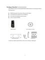
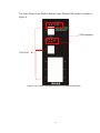
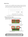
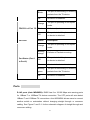
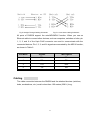
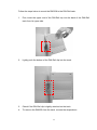
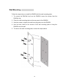
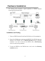
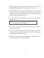
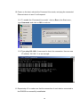
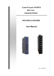
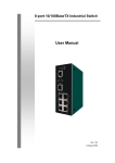
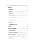
Alloy RNS5/8 Industrial 5-port/8-port Ethernet Rail Switch User’s Manual Rev.1.1 20-Jan-2005 Content Introduction......................................................... 1 Features ................................................................... 1 Package Checklist.................................................... 2 Hardware Description ......................................... 3 Dimensions .............................................................. 3 Front Panel............................................................... 3 Bottom View ............................................................. 5 Wiring the DC Power Inputs..................................... 5 LED Indicators.......................................................... 6 Ports......................................................................... 8 Cabling ..................................................................... 9 DIN-Rail Mounting.................................................. 10 Wall Mounting ........................................................ 12 Hardware Installation........................................ 13 Installation and Testing .......................................... 13 Introduction Industrial environments are usually more demanding than office environments. Harsh temperature conditions, vibration, dust, etc. all put higher demands on the quality and reliability of your networking equipment. To survive harsh industrial environments, Alloy provides you with the RNS5/8 Series Industrial 5-port/8-port 10/100Mbps Ethernet Switches. The RNS5/8 Industrial switch is a cost-effective solution ideal for your industrial applications in harsh environments. The RNS5/8 not only gives you high speed data transmission over an Ethernet network, but also provides redundant power inputs and reverse polarity protection. In addition, the RNS5/8 is manufactured in an IP30 aluminum case, and has passed several safety certifications, ensuring customers a cost-effective, safe, and reliable industrial device. Features 5-port /8-port 10/100T(X) industrial switch Supports store-and-Forward switching architecture Supports IEEE 802.3 10Base-T, 802.3u 100Base-TX standard Supports auto MDI/MDI-X function RNS5: 512 KB embedded memory RNS8: 1024KB embedded memory Supports IEEE 802.3x flow control ¾ Flow control for full-duplex mode ¾ Back pressure for half-duplex mode Provides redundant dual power inputs Aluminum case with IP30 protection RNS5:1K MAC address table RNS8:2K MAC address table DIN-Rail and wall mountable design 1 Package Checklist Alloy RNS5/8 Industrial 5-port/8-port Ethernet Rail Switches are packaged with the following items: RNS5/8 Industrial 5-port/8-port Ethernet Rail Switch One DIN-Rail clip (attached to the RNS5/8) One wall mounting plate and six screws User’s manual CD-ROM RNS5/8 Switch Wall Mounting Plate User’s Manual CD-ROM Screws DIN-Rail Clip Contact your sales representative if any item is missing or damaged. 2 Hardware Description Dimensions RNS5/8 Industrial 5-port/8-port Ethernet Rail Switch dimensions (W x H x D) are 54mm x 135mm x 105mm Front Panel The Front Panel of the RNS5 Industrial 5-port Ethernet Rail Switch is shown in Figure A. LED Indicators UTP Ports Figure A. Front Panel of the RNS5 Industrial 5-port Ethernet Rail Switch 3 The Front Panel of the RNS8 Industrial 8-port Ethernet Rail Switch is shown in Figure A. LED Indicators UTP Ports Figure A. Front Panel of the RNS8 Industrial 8-port Ethernet Rail Switch 4 Bottom View The bottom view of the RNS5/8 Industrial 5-port/8-port Ethernet Rail Switch consists of one terminal block connector with two DC power inputs, Alarm output and one DC IN power jack for an additional AC/DC power adapter. Figure B. Bottom view of the RNS5/8 Industrial 5-port/8-port Ethernet Rail Switch Wiring the DC Power Inputs Follow the steps below to wire RNS5/8 dual DC power inputs. [Note] The suitable electric wire ranges from 12 to 24 AWG. V- V+ V- V+ 1. Insert the positive and negative wires into the V+ and Vcontacts respectively of the terminal block connector 2. Tighten the wire-clamp screws to prevent the DC wires from being loosened. 5 [Note] The additional power jack is designed for office use. LED Indicators There are 5 diagnostic LEDs and 8 Port LEDs located on the Front panel of the RNS5 Industrial Ethernet Rail Switch. These LED indicators provide administrators with real-time system status. Table 1 gives descriptions of the functions of each LED indicator. LED Status Description Green Power is on. Off No power is being supplied. Green Power is on. Off No power is being supplied. Green Power is on. Off No power is being supplied. Green A network device is detected. PWR PWR 1 PWR 2 LNK/ACT of Port 5 Blinks Off Orange FDX/COL of Port 5 Blinks Off The port is transmitting or receiving packets from the TX device. No device is attached. The port is operating in full-duplex mode. Collision of packets occurs. The port is in half-duplex mode or no device is attached. 6 Port LED Status Orange Blinking orange Port Status (Port 1 Description The port is operating in full-duplex mode. Collision of Packets occurring. The port is in half-duplex mode or Off no device is attached. to Port 4) Green A network device is detected. Blinking The port is transmitting or receiving green packets from the TX device. Off No device is attached. Table 1 There are 7 diagnostic LEDs and 12 Port LEDs located on the Front panel of RNS8 Industrial Ethernet Rail Switch. These LED indicators provide administrators with real-time system status. Table 2 gives descriptions of the function of each LED indicator. LED Status Description Green Power is on. Off No power is being supplied. Green Power is on. Off No power is being supplied. Green Power is on. Off No power is being supplied. PWR PWR 1 PWR 2 LNK/ACT of Port 7/8 Green A network device is detected. 7 Blinks Off FDX/COL of Port 7/8 Blinks The port is operating in full-duplex mode. Collision of packets occurs. The port is in half-duplex mode or Off no device is attached. Status Orange Blinking orange Port Status (Port 1 packets from the TX device. No device is attached. Orange Port LED The port is transmitting or receiving Description The port is operating in full-duplex mode. Collision of Packets occurring. The port is in half-duplex mode or Off no device is attached. to Port 6) Green A network device is detected. Blinking The port is transmitting or receiving green packets from the TX device. Off No device is attached. Table 2 Ports RJ-45 ports (Auto MDI/MDIX): RNS5 has five 10/100 Mbps auto-sensing ports for 10Base-T or 100Base-TX device connection. The UTP ports will auto-detect 10Base-T and 100Base-TX connections. Auto MDI/MDIX allows users to connect another switch or workstation without changing straight through or crossover cabling. See Figure C and C-1 for the schematic diagram of straight through and crossover cabling. 8 Fig C Straight Through Cabling Schematic Fig C-1 Cross Over Cabling Schematic All ports of RNS5/8 support the auto-MDI/MDI-X function. When you use an Ethernet cable to connect other devices, such as computers, switches or hubs, pin 1, 2, 3, and 6 of the 8-pin RJ45 connector are used to communicate with the connected devices. Pin1, 2, 3, and 6’s signals are converted by the MDI-X function, as shown in Table 2. Pin MDI-X Signals MDI Signals 1 RD+ TD+ 2 RD- TD- 3 TD+ RD+ 6 TD- RDTable 2 Cabling The cable connection between the RNS5/8 and the attached devices (switches, hubs, workstations, etc.) must be less than 100 meters (328 ft.) long. 9 Mounting Installation DIN-Rail Mounting The DIN-Rail clip is already attached to the RNS5/8 when packaged. If the DIN-Rail clip is not screwed on the RNS5/8, follow the instructions and the figure below to attach the DIN-Rail clip to the RNS5/8. Rear Panel of the RNS5/8 DIN-Rail Clip 1. Use the screws to attach the DIN-Rail clip to the rear panel of the RNS5/8. 2. To remove the DIN-Rail clip, reverse step 1. 10 Follow the steps below to mount the RNS5/8 to the DIN-Rail track: 1. First, insert the upper end of the DIN-Rail clip into the back of the DIN-Rail track from its upper side. 2. Lightly push the bottom of the DIN-Rail clip into the track. 3. Check if the DIN-Rail clip is tightly attached on the track. 4. To remove the RNS5/8 from the track, reverse the steps above. 11 Wall Mounting Follow the steps below to install the RNS5/8 with the wall mounting plate. 1. To remove the DIN-Rail clip from the RNS5/8, loosen the screws from the DIN-Rail clip. 2. Place the wall mounting plate on the rear panel of the RNS5/8. 3. Use the screws to tighten the wall mounting plate onto the RNS5/8. 4. Use the hook holes at the corners of the wall mounting plate to hang the RNS5/8 onto the wall. 5. To remove the wall mounting plate, reverse the steps above. 12 Hardware Installation The following figure illustrates a typical application of RNS5/8 Industrial 5-port/8-port Ethernet Rail Switch. Installation and Testing 1. Take your RNS5/8 Industrial 5-port/8-port Rail Switch out of the package box. 2. Check if the DIN-Rail clip is attached to the RNS5/8. If the DIN-Rail clip is not attached to the RNS5/8, refer to DIN-Rail Mounting section for DIN-Rail installation. If you want to wall-mount the RNS5/8, refer to Wall Mounting section for wall mounting installation. 3. To place the RNS5/8 on the DIN-Rail track or wall, refer to the Mounting Installation section. 13 4. Pull the terminal block off the RNS5/8 and wire the power lines. Refer to the Wiring the DC Power Inputs section for how to wire the power inputs. 5. PWR1 and PWR2 dual power inputs can be connected to power sources simultaneously. When the primary power source fails (the default setting is PWR1), the system will automatically switch to the secondary power source (PWR2), preventing any power interruption. 6. Check the LED for PWR1 and PWR2 to make sure that your RNS5/8 is operating normally. [Note] If you are using DC IN power jack to supply power to the RNS5/8, please check the PWR LED 7. Use Category 5 straight through Ethernet cables with RJ45 connectors to connect network devices. 8. Connect one side of an Ethernet cable with a RJ45 connector to the RNS5/8’s Ethernet port (RJ-45 port), and the other side of the Ethernet cable to the network device’s Ethernet port (RJ-45 port). 9. Check the port status LED indicator (blinking green) on the RNS5/8 to see if the network connection is successfully established. 14 10. Power on the host, activate the Command Line mode, and ping the connected Ethernet device to see if it will respond. 10.1 To enable the “Command Line mode”, click on Run in the Start menu, type Command, and click on OK to continue. 10.2 Type ping 192.168.1.1 command to check the connection. Here we use IP address 192.168.1.1 as an example. 11. Repeat step 10 to make sure that the connection of each device connected to the RNS5/8 is successfully established. 15 12. Power on the host, activate the Command Line mode, and ping the connected Ethernet device by typing “ping –t 192.168.1.1” command to see if it will respond. 13. The parameter ”t” allows you to continue to ping the network device, as shown in the figure below. Before you continue, make sure that both PWR1 and PWR2 are successfully connected to power sources. When PWR1 fails, the LED for PWR1 will go out. At that point, you should notice that the ping command is still responding, this verifies that the redundant power input function is working correctly. 14. Exit the Command Line mode, and connect PWR1 power input. .Your RNS5/8 has been tested and the installation is complete. 16 Trouble shooting Make sure you are using the correct VDC power supplies (12 to 48 VDC) or power adapters. Do not use power adapters with DC output over 48V. It will damage the device. Select Ethernet cables with specifications suitable for your applications to set up your system. Ethernet cables are categorized into unshielded twisted-pair (UTP) and shielded twisted-pair (STP) cables. Category 3, 4, 5 Ethernet cables are suitable for systems with 10 Mbps transmission speed. For systems with 100 Mbps transmission speed, Category 5 Ethernet cables are the only suitable specifications for this environment. You also need to make sure that the distance between each node is not longer than 100 meters (328 feet). If the power indicator does not turn on when the power cord is plugged in, you may have a problem with the power cord. Check for loose power connections, power loss or surges at the power outlet. If you still cannot resolve the problem, contact your local dealer for assistance. 17 Technical Specifications IEEE 802.3 10BaseT Ethernet Standards IEEE 802.3u 100BaseT(X) Fast Ethernet IEEE802.3x Flow Control and Back pressure Protocols CSMA/CD Technology Store and Forward Transmission 14,880 pps for Ethernet port Rate 148,800 pps for Fast Ethernet port MAC address RNS5: 1K MAC address table table size RNS8: 2K MAC address table Memory Buffer RNS5: 512Kbits RNS8: 1024Kbits Per port: Link/Activity (Green) Full duplex/Collision (Orange) LED Per unit: Power, Power 1,Power 2(Green) 10BaseT: twisted-pair UTP/STP Cat. 3, 4, 5 cable Network Cables EIA/TIA-568 100-ohm (100m) 100BaseT(X): twisted-pair UTP/STP Cat. 5 cable EIA/TIA-568 100-ohm (100m) 18 12 to 48 VDC, redundant dual DC power inputs Power Supply with reverse polarity protection, and a removable terminal block for master and slave VDC power inputs. Power RNS5: 2.8 Watts consumption RNS8: 4.6 Watts Packet throughput RNS5: 0.74Mpps @ 64bytes (5TX) ability RNS8: 1.19Mpps @ 64bytes (8TX) Installation DIN-Rail kit and wall mounting panel Operating Temperature Operating Relative Humidity Storage Temperature Storage Relative Humidity -10°C to 70°C 5 to 95% (non-condensing) -40 °C to 85°C 5 to 95% (non-condensing) Dimensions 54 mm (W) x 135 mm (H) x 105mm (D) EMI FCC Class A CE EN6100-4-2, CE EN6100-4-3, EMS CE EN-6100-4-4, CE EN6100-4-5, CE EN6100-4-6 Safety Stability testing UL, CUL, CE/EN60950, IP-30 IEC60068-2-32 (Free fall), IEC60068-2-27 (Shock), 19 IEC60068-2-6 (Vibration) 20