1
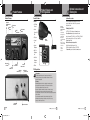
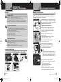
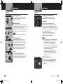
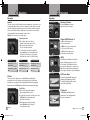
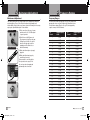
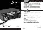
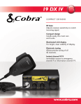
Main Icons Our Thanks, The CB Story, and Customer Assistance Introduction Intro Operation Customer Warranty Assistance Thank you for purchasing the Cobra 19 DX IV CB Radio Transceiver. Properly used, this Cobra product will give you many years of reliable service. The Citizens Band Story Installation Owner’s Manual Main Icons Icons The Citizens Band Secondary lies between the shortwave broadcast and 10-meter amateur radio bands, and was established by law in 1949. The Class D two-way communications service was opened in 1959. (CB also includes a Class A citizens band and Class C remote control frequencies.) Notice Intro microTALK® Radios Customer Warranty For Assistance in the U.S.A. Automated Help Desk English only. 24 hours a day, 7 days a week 773-889-3087 (phone). Customer Notice Assistance Caution Operators Warning English and Spanish. 8:00 a.m. to 5:30 p.m. Central Time, Mon. through Fri. (except holidays) 773-889-3087 (phone). Questions English and Spanish. Faxes can be received at 773-622-2269 (fax). Technical Assistance English only. www.cobra.com (on-line: Frequently Asked Questions). English and Spanish. [email protected] (e-mail). Safety Alert® Traffic Warning Systems Truck-Specific Navigation Systems HighGear® Accessories CobraMarine VHF Radios Power Inverters For Assistance Outside the U.S.A. LED Lights 19DXIV_MANL_vC.indd 17-1 Operation Assistance Customer Assistance Secondary Icons Radar/Laser Detectors Nothing Comes Close to a Cobra® Warning Should you encounter any problems with this product, or not understand its many features, please refer to this owner’s manual. If you require further assistance after Customer reading this manual, Cobra Electronics offers the following Installation Assistance customer assistance services: CB Radios Accessories Caution Customer Assistance The Cobra line of quality products includes: Jumpstarters Customer Assistance Contact Your Local Dealer For more information or to order any of our products, please visit our website: www.cobra.com English MOBILE RADIO 19 DX IV Nothing Comes Close to a Cobra® ©2014 Cobra® Electronics Corporation 6500 West Cortland Street Chicago, Illinois 60707 USA www.cobra.com Printed in China Part No. 480-170-P Version D English A1 English 3/14/14 8:59 AM Main Icons Main Icons Product Features Introduction Intro Product Features Operation Channel 9/ NOR/Channel 19 Button TX Installation Indicator Icon CB/PA Secondary Icons Button Notice Customer Assistance Product Features and FCC Regulations Introduction Warranty Intro Product Features • • 40 CB Radio Channels S/RF Power Meter Operation Customer Assistance LCD Channel Display • Instant Channels 9/19 NOR Installation Notice Caution Talk Button • Dynamic Microphone Main Icons Intro On-Off/ Volume Knob Squelch/ RF Gain Knob Public Address Jack Channel Selector Knob • Nine Foot Microphone Cord Operation Microphone Connector Detail External Secondary Icons Speaker Jack Notice Installation The Cobra line of quality products includes: Secondary Icons CB Radios microTALK® Radios Radar/Laser Detectors Safety Alert® Traffic Warning Systems Notice Truck-Specific Navigation Systems HighGear® Accessories CobraMarine® VHF Radios Power Inverters LED Lights Jumpstarters Accessories Warning Shield RX Customer Warranty Assistance Optional Accessories You can find quality Cobra products and accessories at your local Cobra dealer, or in the U.S.A., you can order Customer directly from Cobra. • Assistance Ordering from U.S.A. Call 773-889-3087 for pricing or visit www.cobra.com. For credit card orders, complete and return this order form to fax number 773-622-2269. Or call 773-889-3087 (Press 1 Warning 8:00 a.m. to 5:30 p.m. Central Time, fromCaution the main menu) Monday through Friday. Make check or money order payable to: Cobra Electronics, Attn: Accessories Dept. 6500 West Cortland Street, Chicago, IL 60707 USA To order online, please visit our website: www.cobra.com TX • Front Panel Customer Warranty Microphone Assistance Connector • RF Gain Installation Operation • Customer Assistance • Compact Size Microphone Connector Intro Secondary Icons • PA System Warning Optional Accessories and Ordering Info Customer Service Warranty Features Customer Assistance Caution Main Icons Audio Customer Assistance FCC Regulations Caution • FCC Regulations FCC regulations permit only “transmission” (one-party to another) rather than “broadcast” (to a wide audience). Thus, advertising is not allowed on CB channels Warning because that is “broadcasting”. FCC Warnings All transmitter adjustments other than those supplied by the manufacturer as front panel operating controls, must be made by, or under the supervision of, the holder of an FCC-issued general Radio-Telephone Operator’s License. Replacement or substitution of transistors, regular diodes or other parts of a unique nature, with parts other than those recommended by Cobra, may cause violation of the technical regulations of Part 95 of the FCC Rules, or violation of Type Acceptance requirements of Part 2 of the Rules. You should read and understand Part 95 (included with this unit) of the FCC Rules and Regulations, before operating your Cobra radio, even though the FCC no longer requires you to obtain an operator’s license. Antenna Connector A2 English 19DXIV_MANL_vC.indd 2-4 Power Connection Nothing Comes Close to a Cobra® A3 Nothing Comes Close to a Cobra® 17 3/14/14 8:59 AM Main Icons Contents Main Icons Introduction Intro Main Icons Intro Intro Operation Main Icons Secondary Icons Installation Secondary Icons Intro Operation Notice Installation Secondary Icons Notice Intro nstallation Customer Assistance Warranty Installation and Start-Up Notice Caution Warning 3 Mounting and Connections. . . . . . . . . . . . . . . . . . . . . . . . . . . . . . . . . . . . . Customer Operating Your Mobile Radio Assistance Operation. . . . . . . . . . . . . . . . . . . . . . . . . . . . . . . . . . . . . . . . . . . . . . . . . . 4 Notice Caution Warning Antenna Connector. . . . . . . . . . . . . . . . . . . . . . . . . . . . . . . . . . . . . . . . . 4 Customer Warranty Assistance External Speaker . . . . . . . . . . . . . . . . . . . . . . . . . . . . . . . . . . . . . . . . . . 4 Public Address (PA) . . . . . . . . . . . . . . . . . . . . . . . . . . . . . . . . . . . . . . . . 4 Power . . . . . . . . . . . . . . . . . . . . . . . . . . . . . . . . . . . . . . . . . . . . . . . . . . 4 Caution Turning on Warning Your Mobile Radio . . . . . . . . . . . . . . . . . . . . . . . . . . . . . . . . 5 Customer Assistance CB Antenna . . . . . . . . . . . . . . . . . . . . . . . . . . . . . . . . . . . . . . . . . . . . . . 5 Microphone Connector. . . . . . . . . . . . . . . . . . . . . . . . . . . . . . . . . . . . . . 5 Squelch. . . . . . . . . . . . . . . . . . . . . . . . . . . . . . . . . . . . . . . . . . . . . . . . . 6 RF Gain . . . . . . . . . . . . . . . . . . . . . . . . . . . . . . . . . . . . . . . . . . . . . . . . . 6 Selecting a Channel. . . . . . . . . . . . . . . . . . . . . . . . . . . . . . . . . . . . . . . . 7 Channel 9/NOR/Channel 19. . . . . . . . . . . . . . . . . . . . . . . . . . . . . . . . . . 7 Caution Warning 7 CB/PA. . . . . . . . . . . . . . . . . . . . . . . . . . . . . . . . . . . . . . . . . . . . . . . . . . . S/RF Power Meter . . . . . . . . . . . . . . . . . . . . . . . . . . . . . . . . . . . . . . . . . 7 TX Indicator LED. . . . . . . . . . . . . . . . . . . . . . . . . . . . . . . . . . . . . . . . . . . 7 Ignition Noise Interference. . . . . . . . . . . . . . . . . . . . . . . . . . . . . . . . . . . 8 Temporary Mobile Operation . . . . . . . . . . . . . . . . . . . . . . . . . . . . . . . . . 8 Operating Procedure to Receive. . . . . . . . . . . . . . . . . . . . . . . . . . . . . . . 9 Operating Procedure to Transmit. . . . . . . . . . . . . . . . . . . . . . . . . . . . . . 9 Maintenance/Adjustment . . . . . . . . . . . . . . . . . . . . . . . . . . . . . . . . . . . . . 10 Frequency Ranges . . . . . . . . . . . . . . . . . . . . . . . . . . . . . . . . . . . . . . . . . . 11 Specifications. . . . . . . . . . . . . . . . . . . . . . . . . . . . . . . . . . . . . . . . . . . . . . 12 Warranty Limited One-Year Warranty. . . . . . . . . . . . . . . . . . . . . . . . . . . . . . . . . . . . 13 in Icons Operation Operation Introduction Our Thanks to You. . . . . . . . . . . . . . . . . . . . . . . . . . . . . . . . . . . . . . . . . . A1 A1 The Citizens Band Operation CustomerStory. . . . . . . . . . . . . . . . . . . . . . . . . . . . . . . . . . . . . . Warranty Assistance . . . . . . . . . . . . . . . . . . . . . . . . . . . . . . . . . . . . . . . . A1 Customer Assistance Customer Installation Product Features. . . . . . . . . . . . Assistance . . . . . . . . . . . . . . . . . . . . . . . . . . . . . . . . A2 A3 FCC Regulations. . . . . . . . . . . . . . . . . . . . . . . . . . . . . . . . . . . . . . . . . . . . Secondary Icons Warnings . . . . . . . . . . . . . . . . . . . . . . . . . . . . . . . . . . . . . . . . . . . . . . . . . . 2 Customer Warranty Customer Installation Included Package. . . . . . . . . . . . . . . . . . . . . . . . . . . . . . . . . . . . . . . 2 Assistance in this Assistance Customer Assistance Operation Customer Assistance Warranty Customer Assistance Customer Assistance Product Service . . . . . . . . . . . . . . . . . . . . . . . . . . . . . . . . . . . . . . . . . . . . 14 Accessories . . . . . . . . . . . . . . . . . . . . . . . . . . . . . . . . . . . . . . . . . . . . . . . 16 Warranty Optional Accessories and Ordering Info . . . . . . . . . . . . . . . . . . . . . . . . . . 17 Nothing Comes Close to a Cobra® Installation Customer Assistance 1 condary Icons Notice 19DXIV_MANL_vC.indd Caution Warning 1 3/14/14 8:59 AM Main Icons Intro Operation Customer Assistance Introduction Customer Assistance Warnings Secondary Icons Intro Operation Customer Assistance Notice Caution Customer Assistance Installation ain Icons Intro Warnings and Included in this Package Warranty ain Icons Installation Main Icons Intro Operation Customer Assistance Intro Installation Operation Customer Customer Assistance Warranty Assistance Mounting and Connections • Caution Customer Assistance Customer Assistance Installation econdary Icons Notice Caution A FEW RULES THAT SHOULD BE OBEYED Notice Caution Warning 1. You are not allowed to carry on a conversation with another station for more than five minutes at a time without taking a one-minute break to give others a chance to use the channel. Warning You are not allowed to blast others off the air by overpowering them with illegally amplified 2.Warranty transmitter power or illegally high antennas. 3. You are not allowed to use CB to promote illegal activities. 4. You are not allowed to use profanity. 5. You may not play music in your CB. 6. You may not use your CB to sell merchandise or professional service. remotsuC ecnatsissA You should find all of the following items in this package: CB Transceiver Microphone noitallatsnI Antenna Connector Main Icons snocI yradnoceS snocI niaM gninraW noituaC ecitoN Operating Manual remotsuC ecnatsissA noitarepO English 19DXIV_MANL_vC.indd 2-3 To mount and connect Caution Warning your transceiver: 1. Hold the radio with mounting bracket in the exact location desired. Remove the mounting bracket and use it as a template to mark the location for the mounting screws. 2. Drill necessary holes and secure mounting bracket in location. 3. Connect the antenna cable plug to the receptacle marked “ANT” on the back of the unit. Operation Customer Warranty 4. Connect the red lead of the DC power cord Assistance to an accessory 12 volt fuse. 5. Connect the black lead to the negative side of the Customer automobile. This is usually the chassis. Installation Assistance Any convenient location with good electrical contact (remove paint) may be used. ortnI Icons Secondary NOTE Before installing the CB radio, visually check the vehi Notice Caution Warning cle battery connections to determine which battery remotsuC noitallatsnI ecnatsissA Microphone Connector terminal, positive or negative (positive is the larger of the two) is grounded to the engine block (or chassis). snocI yradnoceS • Transceiver Bracket gninraW ecitoN noituaC 2 Intro Fuse Connection Microphone Bracket • Notice CB Tranceiver ytnarraW Included in this Package Warranty snocItransceiver niaM Select a location for the and microphone bracket that is convenient for operation. In automobiles, the transceiver is usually mounted to the underneath of the Customer dash panel, with the microphone Installation bracket beside it. Assistance A universal mounting bracket is supplied along with self tap Transceiver Bracket Caution Warning Secondary Icons Notice ping screws and star washers. The transceiver is held in the universal mounting bracket by two thumb screws, permitting remotsuC noitarepO ortnI adjustment at the most convenient angle. ecnatsissA CHANNEL 9 EMERGENCY MESSAGES Use Channel 9 for emergency messages only. The FCC gives the following examples of Warning permitted and prohibited types of communications for use on Channel 9. These are guidelines and are not intended to be all-inclusive. Permitted: “A tornado sighted six miles of town.” Not Permitted: “This is observation post number 10. No tornado sighted.” Warranty Secondary Icons REPLACEMENT WARNING Warranty Replacement or substitution of certain parts with replacements other than those recommended by Customer Installation Cobra may be a violation of the technical regulations of Part 95 Assistance Warning of the FCC rules, or of Type Acceptance requirements of Part 2 of those rules. Secondary Icons When making adjustments, be sure to re-read applicable portions of this instruction manual to make certain you are following correct procedure and that the radio was properly installed. ytnarraW Notice Operation Customer Assistance Mounting and Connections Introductionand Start-Up Installation econdary Icons Intro Operation 6. Mount the microphone bracket on right side of the transceiver or near it using two screws supplied. When mounting in an automobile, place the bracket under the dash so the microphone is readily accessible. 7. Attach the four pin microphone cable to receptacle on front of unit and install unit in bracket securely. Nothing Comes Close to a Cobra® 3 3/14/14 8:59 AM Intro Operation Main Icons ytnarraW remotsuC ecnatsissA noitarepO ortnI Operating Your Mobile Radio snocI niaM Intro Operation Operation remotsuC ecnatsissA Antenna Connector ytnarraW remotsuC ecnatsissA noitallatsnI Main Icons noituaC remotsuC ecnatsissA Operation Customer Assistance Operating Your Mobile Radio Secondary Icons Warranty Antenna Connector Intro noituaC • Customer Warranty External Speaker Assistance Operation Notice Installation Caution Warning Public Address (PA) PA Speaker Jack An external PA speaker may be connected Secondary Icons to the PA speaker jack when used as a public address system. The speaker should be directed away from the microphone to prevent acoustic Intro Operation Customer Warranty Assistance feed-back. Physical separation or isolation of the microphone and speaker must be employed Notice Caution Warning when operating the PA at high output levels. ytnarraW These wires supply Power to the CB radio. This cable is permanently attached to the radio. If you wish to remove the radio after installation, disconnect at fuse holder and ground connector. remotsuC ecnatsissA Secondary Icons Notice Caution English 19DXIV_MANL_vC.indd 4-5 Secondary Icons Warranty Turning on Your Mobile Radio • Main Icons CB Antenna NOTE Cobra loaded-type antenna models HGA 1000, HGA Notice Caution Warning snocI niaM 1500 and HGA 2000 are highly recommended for most installations. Consult your Cobra dealer for further details (or see order form on page 17). Three-way combination antennas are available which allow operation of all three bands (AM-FM and CB), using a single antenna. However, use noitarepO ortnI of this type of antenna usually results in less than normal transmit and receive range when compared to a standard-type “Single Band” antenna designed for CB only. remotsuC noitallatsnI ecnatsissA Microphone Connector Microphone Connector Allows for convenient removal of the Microphone plug snocI yradnoceS when storage is required. The Microphone MUST be connected to the unit at all times, when in use, for proper operation. Warning gninraW 4 Customer Assistance Only a properly matched Antenna system will allow maximum power output. In mobile installations (cars, trucks, Warning boats, etc.), an Antenna system that is nonNotice Caution Intro Operation Customer Warranty directionalAssistance should be used. When installed in a boat, the transceiver will not operate at maximum efficiency without a ground plate unless the vessel has a steel hull. Before installing the transceiver Customer Installation Assistance in a boat, consult your dealer for information Secondary Icons regarding an adequate grounding system. Customer Assistance Customer Power Cable Installation Power Assistance Operation Turn the On-Off/Volume knob clockwise to turn Notice Caution Customer Warning Installation Assistance the power on and set the desired listening volume. NOTE Cobra external speakers are rated 15 watts. Main Icons ecitoN Operation On-Off/Volume Knob ecitoN The external speaker jack on the rear panel is used forCaution an External Speaker. The external speaker should have noitallatsnI Notice Warning External Speaker Jack 8-ohm impedance and be rated to handle at Customer Installation Assistance snocI yradnoceS least 4.0 watts. When the external speaker is plugged in, Secondary Icons the internal speaker is automatically disconnected. Intro Operation Customer Warranty Intro Operation Assistance gninraW Warranty Customer Assistance Installation This female Connector on the rear panel permits snocI yradnoceS Customer Installation Assistance connection of the transmission line cable male noitarepO ortnI connector to the transceiver. Secondary Icons Main Icons gninraW Customer Assistance Main Icons noituaC ecitoN Nothing Comes Close to a Cobra® 5 3/14/14 8:59 AM Main Icons Main Icons Installation Operation Main Icons Operating Your Mobile Radio Intro Operation Operation Squelch Intro Operation Customer Assistance Customer Assistance Secondary Icons Warranty Intro Notice Adjust Squelch/RF Gain Knob Notice Caution Warning Main Icons Intro • Warning ToCaution squelch your radio: 1.Full clockwise rotation closes the gate, allowing only very strong signals to enter. 2.Full counterclockwise rotation opens the “gate,” allowing all signals in. 3.To achieve the Desired Squelch Setting (DSS), turn the Squelch control counterclockwise until you hear noise. Now turn the control clockwise just until the noise stops. This is the DSS setting. Gate Closed Gate Open Desired Squelch Setting (DSS) Strong Signals Strong Signals Strong Signals Medium Signals Medium Signals Medium Signals Weak Signals Weak Signals Weak Signals Noise Noise Noise Operation Customer Assistance Operation Warranty ytnarraW remotsuC ecnatsissA Secondary Icons Notice Caution 6 English 19DXIV_MANL_vC.indd 6-7 Warning Customer Assistance Warranty • Selecting a Channel Rotate the ChannelWarning knob clockwise Customer Notice Caution Installation noitarepO ortnI Assistance until desired channel is displayed. Secondary Icons remotsuC ecnatsissA noitallatsnI Channel 9/NOR/Channel 19 Button Notice snocI yradnoceS gninraW noituaC Channel 9/NOR/Channel 19 Caution Warning Set CH 9 to obtain instant access Intro Operation Customer Warranty to the emergency channel. Assistance Set NOR position to use the channel knob to choose any of the 40 channels. ecitoN Set CH 19 to obtain instant access to Customer the information and calling channel. Installation Assistance CB/PA Button Secondary Icons CB/PA In the CB position, the PA function is disabled and the unit will transmit and receive on the selected channel. The PA function should not be used unless a PA speaker is connected. In the Notice Caution Warning snocI niaM PA position, the transmit function is disabled and the microphone output will go only to the PA speaker. S/RF Power Meter Adjust Squelch/RF Gain Knob Operation Main Icons RF Gain This control is used to adjust receiver sensitivity. Maximum sensitivity allows weak signals Customer to be received. However, very strong signals (such as from a nearby Installation Assistance transmitter) can cause distortion at that setting. Adjust until the distortion disappears. Reducing the receiver’s RF Gain eliminates distortion from very strong incoming signals. Operation Channel Selector Knob Warranty T his control is used to cut off or Customer eliminate receiver background noise in the absence of an Installation incoming signal. Adjust until the Assistance receiver noise disappears. This will require the incoming signal toSecondary be slightly stronger than average receiver noise. Further clockwise rotation will Icons Customer Installation the threshold level which a signal must overcome in order to be heard. Only increase Assistance strong signals will be heard at a maximum clockwise setting. Squelch is the “control gate” for incoming signals. Secondary Icons snocI niaM Operating Your Mobile Radio Customer Assistance ytnarraW To set RF Gain: 1. Full counterclockwise rotation minimizes gain for maximum distortion control. 2. To achieve the desired level of distortion control, turn the RF Gain knob counterclockwise until the distortion is eliminated. 3. After moving away from the strong signal, gninraW turn the RF Gain knob fully clockwise to receive all possible signals. remotsuC ecnatsissA remotsuC ecnatsissA noituaC S/RF Power Meter TX Indicator Shows relative transmitter RF output power and input signal strength when receiving. noitarepO ortnI The Liquid Crystal Display (LCD) segments increase with signal strength. noitallTX atsnIndicator I The TX Indicator will light when in the snocI yradnoceS transmit mode. “Busy” will appear when there is an incoming signal. ecitoN Nothing Comes Close to a Cobra® 7 3/14/14 8:59 AM Intro Main Icons Customer Assistance Warranty Main Icons Operating Your Mobile Radio Intro Operation Operation Operation Customer Assistance Installation Operating Your Mobile Radio Secondary Icons Warranty Ignition Noise Interference • PA ytnarraW Installation Notice Notice remotsuC ecnatsissA 13.8V DC 19DXIV_MANL_vC.indd 8-9 Caution Installation remotsuC ecnatsissA noituaC snocI niaM Customer Assistance Customer Assistance Warranty Warranty Operating Procedure to Receive Adjust Squelch/RF Gain Knob ANT English Operation Operation Secondary Icons EXT gninraW Notice Secondary Icons For Temporary Mobile Operation, you may want to purchase an additional cigarette Customer Installation Assistance lighter adapter from your Cobra dealer. This adapter and a magnetic mount antenna allow Secondary Icons you to quickly “install” your transceiver for temporary use. NOTE Red Wire is connected to positive side Notice Caution Warning of socket center tip. Black Wire is connected to negative side contacts. Radio resets to CH 9 when connected to cigarette lighter plug. When using the unit with cigarette adapter, turn off when not in use to avoid draining the battery. Operation Customer Assistance On-Off/Volume Knob Temporary Mobile Operation Temporary Mobile Operation Intro Operation Intro Use of a mobile receiver at low signal levels is normally limited by the presence Customer Installation Assistance conditions, when signal level is adequate, of electrical noise. Under most operating the background Secondary Iconsnoise does not present a serious problem. Also, when extremely low level signals are being received, the transceiver may be operated with vehicle engine turned off. The unitMainrequires very little current and therefore will not significantly discharge Icons the vehicle battery. Even though this radio has noise limiter, in some installations Notice an automatic Caution Warning ignition interference may be high enough to make good communications impossible. Consult your authorized Cobra dealer or a two-way radio technician Operation Customer Warranty for help in locating andIntro correcting the source Assistanceof severe noise. 8 Operation Main Icons • Customer B e sure that power cord, antenna and microphone Warning Assistance are connected to the proper connectors before proceeding Customer further. The CB/PA switch should be Assistance in the CB position. To receive: 1.Turn the radio on by rotating the Caution Warning On-Off/Volume knob clockwise. 2.Rotate the Squelch/RF Gain knob Caution Warning until incoming counterclockwise signal is heard. 3.Select the desired channel. 4.Set the On-Off/Volume knob and the Squelch/RF Gain knob to a comfortable listening level. Operating Procedure to Transmit noitarepO ortnI e sure the antenna is properly connected to the radio before transmitting. Prolonged B transmitting without an antenna, or with a poorly matched antenna, could cause damage to the transmitter. Press-to-Talk Switch noitallatsnI ecitoN snocI yradnoceS To transmit: 1.Select the desired channel. 2.The receiver and transmitter are controlled by the Press-to-Talk switch on the microphone. Press the switch and the transmitter is activated; release switch to receive. When transmitting (on a clear channel), hold the microphone two inches from the mouth and speak clearly in a normal voice. Nothing Comes Close to a Cobra® 9 3/14/14 8:59 AM Main Icons Main IconsMain Icons Operating Your Mobile Radio Intro Operation Maintenance/Adjustment Customer Assistance Maintenance/Adjustment Operating Your Mobile CB Radio Radio Warranty Intro • Your Cobra CB transceiver is specifically designed for the environment encountered in mobile installations. The use of all solid state circuitry and its light weight result in high reliability. Should a failureCustomer occur, however, review the following, then if necessary, Installation Assistance replace parts only with identical parts. Do not substitute. Secondary Icons 1.Check connections to the source of power Check Power Source and make sure it is the 13.8 VDC required to operate your radio. 2. Check the fuses in the DC power cord. Notice Caution Warning The main power lead (red) has a two amp 3AG type fuse in its holder. Use only the above specified type and size fuse for maximum protection. Failure to do so Check Fuses in DC Power Cord will void the warranty. 3.Make certain the microphone is properly plugged in. 4.Make certain the antenna is properly assembled and connected. If you are unable to correct the problem, refer to product service on page 14 for the correct procedure for warranty and Check Microphone Connection post-warranty service from Cobra. Check Antenna Connection 10 English 19DXIV_MANL_vC.indd 10-11 Frequency Ranges IntroOperationOperation Customer CustomerWarranty Warranty AssistanceAssistance Frequency Ranges • The Cobra 19 DX IV transceiver represents one of the most advanced AM two-way radios for use as a Class D station in the Citizens Radio Service. Customer Customer This unit features advanced Installation Installation Phase Lock Loop (PLL) circuitry providing AssistanceAssistance complete coverage of all 40 CB channels. SecondarySecondary Icons Icons CBChannel Frequency Channel in MHz CBChannel Frequency Channel in MHz 1 Notice 26.965 21 27.215 2 26.975 22 27.225 3 26.985 23 27.255 4 27.005 24 27.235 5 27.015 25 27.245 6 27.025 26 27.265 7 27.035 27 27.275 8 27.055 28 27.285 9 27.065 29 27.295 10 27.075 30 27.305 11 27.085 31 27.315 12 27.105 32 27.325 13 27.115 33 27.335 14 27.125 34 27.345 15 27.135 35 27.355 16 27.155 36 27.365 17 27.165 37 27.375 18 27.175 38 27.385 19 27.185 39 27.395 20 27.205 40 27.405 Notice Caution Caution Warning Warning Nothing Comes Close to a Cobra® 11 3/14/14 8:59 AM Main Icons Main Icons Specifications Operating Your Mobile Radio Intro Operation Specifications Customer Assistance Warranty Intro Warranty Operation • General Channels Installation Frequency Range Customer Assistance Secondary Icons Frequency Tolerance CB – 40 CH CB – 26.965 to 27.405 MHZ 0.005 % Installation Secondary Icons Frequency Control PLL (Phase Lock Loop) Synthesizer Operating Temperature Range Microphone Notice Caution -30° C TO + 65° C Warning Plug-in Condenser Input Voltage 13.8VDC nom. (negative ground) Current DrainTransmit: AM full mod., 1.4A (maximum) Receive: Squelched, 0.9 A; full audio output, 1.2A (nominal) Size 6 7⁄8” D x 6 3⁄4” W x 17⁄8” H Weight 3.25 lbs. Antenna Connector UHF; SO-239 MeterLCD’s; indicates relative power output and received signal strength Transmitter Warranty and Trademark Acknowledgement Notice Customer Warranty Assistance Limited One-Year Warranty Power Output 4 watts Modulation AM (Amplitude Modulation) Frequency Response 300 to 3000 Hz Output Impedance 50 ohms, unbalanced For Products Purchased Outside the U.S.A. Please contact your local dealer for warranty information. Sensitivity Less than 1 µV for 10dB (S+N) Selectivity 6 dB @ 7 KHz, 60 dB @ 10KHz Trademark Acknowledgement Image Rejection 60 dB, typical Adjacent-Channel Rejection 50 dB, typical Automatic Noise Limiter Built-in Receiver 12 English 19DXIV_MANL_vC.indd 12-13 • For Products Purchased in the U.S.A. Cobra Electronics Corporation warrants that its Cobra CB radios, and the component parts Customer Assistance thereof, will be free of defects in workmanship and materials for a period of one year from the date of first consumer purchase. This warranty may be enforced by the first consumer purchaser, provided that the product is utilized within the U.S.A. Cobra will, without charge, repair or replace, at its option, defective CB radios, products or component parts upon delivery to the Cobra Factory Service department, accompanied by proof of the date of first consumer purchase, such as a duplicated copy of a sales receipt. Caution Warning You must pay any initial shipping charges required to ship the product for warranty service, but the return charges will be at Cobra’s expense, if the product is repaired or replaced under warranty. This warranty gives you specific legal rights, and you may also have other rights which may vary from state to state. Exclusions: This limited warranty does not apply: 1) To any product damaged by accident; 2) In the event of misuse or abuse of the product or as a result of unauthorized alterations or repairs; 3) If the serial number has been altered, defaced or removed; 4) If the owner of the product resides outside the U.S.A. All implied warranties, including warranties of merchantability and fitness for a particular purpose are limited in duration to the length of this warranty. Cobra shall not be liable for any incidental, consequential or other damages; including, without limitation, damages resulting from loss of use or cost of installation. Some states do not allow limitations on how long an implied warranty lasts and/or do not allow the exclusion or limitation of incidental or consequential damages, so the above limitations may not apply to you. • Cobra®, Nothing Comes Close to a Cobra® and the snake design are registered trademarks of Cobra Electronics Corporation, USA. Cobra Electronics Corporation™ is a trademark of Cobra Electronics Corporation, USA. Nothing Comes Close to a Cobra® 13 3/14/14 8:59 AM Main Icons Main Icons Customer Assistance Intro Secondary Icons Operation Intro Customer Assistance Product Service Main Icons Product Service Operation Warranty Customer Assistance Warranty If you have any questions about operation or installing your new Cobra product, or if you are missing parts… Customer Customer Installation Installation Please call Cobra first! DO NOT RETURN THIS PRODUCT TO THE STORE! Assistance Assistance See customer assistance on page A1. Secondary Icons For Products Purchased in the U.S.A. If your product should require factory service, please call Cobra first before sending your radio. This will ensure the fastest turn-around timeWarning on your repair. You may be asked to Notice Caution Notice Caution Warning send your radio to the Cobra factory. It will be necessary to furnish the following to have the product serviced and returned. 1. For warranty repair include some form of proof-of-purchase, such as a mechanical reproduction or carbon of a sales receipt. If you send the original receipt, it cannot be returned. 2. Send the entire product. 3. Enclose a description of what is happening with the radio. Include a typed or clearly printed name and address of where the radio is to be returned. 4. Pack radio securely to prevent damage in transit. If possible, use the original packing material. 5. Ship prepaid and insured by way of a traceable carrier such as United Parcel Service (UPS) or Priority Mail to avoid loss in transit to Cobra Factory Service, Cobra Electronics Corporation, 6500 West Cortland Street, Chicago, Illinois 60707 U.S.A. 6. If the radio is in warranty, upon receipt of your radio it will either be repaired or exchanged depending on the model. Please allow approximately three to four weeks before contacting Cobra for status. If the radio is out of warranty, a letter will automatically be sent informing you of the repair charge or replacement charge. If you have any questions, please call 773889-3087 for assistance. 14 English 19DXIV_MANL_vC.indd 14-15 Customer Assistance Intro • Secondary Icons Operation Customer Product Service Warranty Assistance For Products Purchased in Canada For out of warranty service, ship prepaid this product to: AVS Technologies Inc., 2100 Trans Canada Hwy S., Montreal, Quebec, H9P 2N4. We reserve the right to repair or replace the radio with an equivalent product. Please include the following Customer Installation Assistance information: Date of Purchase, Model Number, Dealer Purchased From, Dealer Address, Dealer Phone Number. For Products Used in Canada Industry Canada Notice Notice is subject Caution to the Warning Operation following two conditions: 1) this device may not cause interference, and 2) this device must accept any interference, including interference that may cause undesired operation of this device. For Products Purchased Outside the U.S.A. or Canada Please contact your local dealer for product service information. Nothing Comes Close to a Cobra® 15 3/14/14 8:59 AM Main Icons Customer Assistance Intro Operation Customer Assistance Accessories Accessories Warranty • Replacement Microphone Bracket Installation Replacement Mounting Bracket Replacement Thumb Screws Customer Assistance Secondary Icons 741-080-9-001 Notice Four Pin Premium Caution Noise-Cancelling Microphone HG M84 Four Pin Replacement Dynamic Microphone HG M73 21” Base Loaded Magnet Mount Antenna HG A1000 Dynamic External Speaker HG S100 251-353-9-001 Warning 634-081-9-001 Four Pin Premium NoiseCancelling Microphone HG M84W Wood Grain Four Pin Noise Canceling Microphone HG M77 38” Base Loaded Magnet Mount Antenna HG A1500 Noise Canceling External Speaker HG S300 Four Pin Power Microphone HG M75 54” Base Loaded Magnet Mount Antenna HG A2000 Noise Canceling With Talk Back External Speaker HG S500 16 English 19DXIV_MANL_vC.indd 16 3/14/14 8:59 AM