1
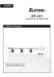
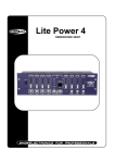
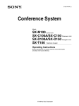
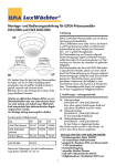
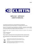
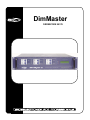
DimMaster
ORDERCODE 50378
Congratulations!
You have bought a great, innovative product from Showtec.
The Showtec DimMaster brings excitement to any venue. Whether you want simple plug-&-play action or a
sophisticated DMX show, this product provides the effect you need.
You can rely on Showtec, for more excellent lighting products.
We design and manufacture professional light equipment for the entertainment industry.
New products are being launched regularly. We work hard to keep you, our customer, satisfied.
For more information: [email protected]
You can get some of the best quality, best priced products on the market from Showtec.
So next time, turn to Showtec for more great lighting equipment.
Always get the best -- with Showtec !
Thank you!
Showtec
Showtec DimMaster™ Product Guide
Warning..…...................................................................................………………………………………….
2
Safety-instructions………………………………………………………………………………………….…. 2
Operating Determinations……………………………………………………………………………………. 3
Description..…..............................................................................……….…………………………………
Backside…….……………………………………………………………………………………….……...….
4
5
Harting Connector – Pin Connection………………………………………………….……………………..
7
Installation...............................................................................…...…………………………………….…..
Installing DimMaster ....................................................……………………………….……..……………
8
8
Set Up and Operation.....................................................................……..…………………………………
Menu System….…….......................................................................……….…………………………….
- Set DMX Address.……….....................................................................................……………….
- Set Channel.……….......................................................................................................………...
- Set Scenes………...............................................................................................……..………....
- Test Channels............................................................................................……………………....
- Set Inputs.................................................................................................................……............
- Unit Set Up.....................................................................................................................……......
- Set Text......................................................................................................................………......
- Software Rev................................................................................................................…...........
- Read Info.......................................................................................................................………...
8
8
9
10
12
15
15
15
15
16
16
Additional Information............................................................................................................................
18
Maintenance...................................................................................………..………….…….……………... 19
Replacing the Fuse........................................................................…………………….………………… 19
Troubleshooting............................................................................………………….………………….…..
19
Product Specifications.................................................................……………….…….………………….
20
1
WARNING
CAUTION!
Keep this device away from rain and moisture!
FOR YOUR OWN SAFETY, PLEASE READ THIS USER MANUAL CAREFULLY
BEFORE YOUR INITIAL START-UP!
SAFETY INSTRUCTIONS
Every person involved with the installation, operation and maintenance of this device has to:
be qualified
follow the instructions of this manual
CAUTION! Be careful with your operations.
With a dangerous voltage you can suffer
a dangerous electric shock when touching the wires!
Before your initial start-up, please make sure that there is no damage caused by transportation. Should there
be any, consult your dealer and do not use the device.
To maintain perfect condition and to ensure a safe operation, it is absolutely necessary for the user to follow
the safety instructions and warning notes written in this manual.
Please consider that damages caused by manual modifications to the device are not subject to warranty.
This device contains no user-serviceable parts. Refer servicing to qualified technicians only.
IMPORTANT:
The manufacturer will not accept liability for any resulting damages caused by the non-observance
of this manual or any unauthorized modification to the device.
•
•
•
•
•
•
•
•
•
•
•
•
•
Never let the power-cord come into contact with other cables! Handle the power-cord and all
connections with the mains with particular caution!
Provide occasional ventilation during use.
Place this unit in a stable location, away from humidity, vibration or bumps.
Never remove warning or informative labels from the unit.
Do not insert objects into air vents.
Do not switch the device on and off in short intervals, as this would reduce the system’s life.
Do not open the device.
Only use device indoor, avoid contact with water or other liquids.
Avoid flames and do not put close to flammable liquids or gases.
Always disconnect power from the mains, when device is not used or before cleaning! Only handle
the power-cord by the plug. Never pull out the plug by tugging the power-cord.
Make sure that the available voltage is not higher than stated on the rear panel.
Make sure that the power-cord is never crimped or damaged. Check the device and the powercord from time to time.
In case of a malfunction (burning smell, etc.), immediately stop operation, disconnect power and
contact your Showtec dealer.
2
•
•
•
•
•
•
•
If device is dropped or struck, disconnect mains power supply immediately. Have a qualified
engineer inspect for safety before operating.
If the device has been exposed to drastic temperature fluctuation (e.g. after transportation), do not
switch it on immediately. The arising condensation water might damage your device. Leave the
device switched off until it has reached room temperature.
If your Showtec device fails to work properly, discontinue use immediately. Pack the unit securely
(preferably in the original packing material), and return it to your Showtec dealer for service.
For replacement use fuses of same type and rating only.
This device falls under protection class I. Therefore it is essential to connect the yellow/green
conductor to earth.
Repairs, servicing and electric connection must be carried out by a qualified technician.
WARRANTY: Till one year after date of purchase.
OPERATING DETERMINATIONS
If this device is operated in any other way, than the one described in this manual, the product may suffer
damages and the warranty becomes void.
Any other operation may lead to dangers like short-circuit, burns, electric shock, explosion, crash etc.
You endanger your own safety and the safety of others!
Improper installation can cause serious damage to people and property !
3
Description of the device
Features
• 6 Channel DMX 512 Dimmingpack, 6x16A
• Inductive and resistant load
• DMX connector by 3p XLR
• 6 DMX channels, 24 map in DMX channels
• 24 programmable scenes
• 10 shows from 24 programmed scenes
• 90 built-in chase programs
• Each channel can be programmed with preheat level(0-20%), maximum output level(30-100%),
control curve(linear, square and switch) and fade time(0.0s-999s).
• Each scene can be programmed with the current output and fade time
• 24 map in DMX channels can be preset mapped to any of 10 scenes, 10 shows and 90 chase programs.
• DMX only and Map only can be selectable
• Several units can be linked in Master/Slave mode
• Switch off protection in the event of over temperature
• LCD display
• Power failure memory
Overview
Fig. 1
1) Circuit Breaker 16A
2) LCD Display: Shows the current activities or adjustments of menus
3) UP Button: Scroll through the menus or increase the values.
4) DOWN Button: Scroll through the menus or decrease the values.
5) YES Button: Enter a submenu or store the settings.
6) NO Button: Leave the settings unchanged or go back one level of the menus.
4
There are 3 versions from the DimMaster:
Standard version ordercode 50378
Ilme 16 Pole Multipin-version ordercode 50378M
Schuko-version ordercode 50378S
Rear Panel
Fig. 2
7) DMX In: 3-pin XLR male, used to receive DMX data.
8) Analog Din
9) DMX Out: 3-pin XLR female, used to transmit DMX data.
10) Terminal Outputs
11) Power Input: Single phase input or three-phase input
(For details, please refer to the wiring diagram printed on the top cover (also see Page 6).
Dim-Master 6 (2 x 16 p. multiconnectors)
Ordercode 50378-M
Dim-Master 6 (6 x Schuko connectors)
Ordercode 50378-S
Fig. 3
5
6
Harting Connector – Pin Connection
1) Channel 1 Phase
2) Channel 2 Phase
3) Channel 3 Phase
4) Channel 4 Phase
5) Channel 5 Phase
6) Channel 6 Phase
7) Not Connected
8) Not Connected
9) Channel 1 Neutral
10) Channel 2 Neutral
11) Channel 3 Neutral
12) Channel 4 Neutral
13) Channel 5 Neutral
14) Channel 6 Neutral
15) Not Connected
16) Not Connected
7
Installation
Remove all packing materials from the DimMaster. Check that all foam and plastic padding is removed.
Screw the equipment onto the wall. Connect all cables.
Always disconnect from electric mains power supply before cleaning or servicing.
Damages caused by non-observance are not subject to warranty.
Set Up and Operation
Before plugging the unit in, always make sure that the power supply matches the product specification
voltage. Do not attempt to operate a 120V specification product on 230V power, or vice versa.
When power is applied to your dimmer, a self-test is performed, as indicated by its LCD. The LCD reads "DMX
ABSENT/ DMX RECEIVED OK/ DMX SIGNAL ERROR" or "OVER TEMPERATURE".
After these initial test, a text message begins to scroll through the LCD. By default these messages are
"DIGITAL DIM PACK ......". You may change these text using menu item 71.
Menu System
Tap the UP/DOWN button to scroll through this menu system. There are total 9 main menus, the table below
shows every main menu and also gives you an explanation.
8
1. SET DMX ADDRESS ?
1. Tap the UP/DOWN button to scroll to "1 SET DMX ADDR?".
1 SET DMX ADDR ?
2. Press YES to enter next menu level, Start Address and Patch Address are selectable using the
UP/DOWN buttons.
Start Address
1. Tap the UP/DOWN buttons to scroll to the sub-menu "11 START ADDR?",
the LCD shows
2. Press YES, the LCD shows
1 SET DMX ADDR ?
11 START ADDR ?
1 SET DMX ADDR ?
111 START [ 1]
3. Tap the UP/DOWN buttons to select desired DMX address(1~512) for the
start channel, its default address is 1.
4. Press YES to store your setting, the LCD shows
1 SET DMX ADDR ?
STORED OK
Patch Address
1. Tap the UP/DOWN buttons to scroll to the sub-menu "12 PATCH ADDR?",
the LCD shows
2. Press YES, the LCD shows
You may select the desired channel by using the UP/DOWN-buttons.
3. Press YES again, the LCD shows
1 SET DMX ADDR ?
12 PATCH ADDR ?
1 SET DMX ADDR ?
121 CHANNEL [ 1]
1 SET DMX ADDR ?
1211 ADDR [ 1]
4. Tap the UP/DOWN buttons to select desired DMX Address(1~512).
5. Press YES to store your setting, the LCD shows
1 SET DMX ADDR ?
STORED OK
6. Repeat steps II~V until every DMX channel has a separate address.
9
2. SET CHANNEL ?
1. Tap the UP/DOWN buttons to scroll to "2 SET CHANNELS?"
2. Press YES to enter next menu level, you may select 21 SET PREHEAT / 22 SET MAX OUT/ 23 SET CURVES/ 24 SET
FADE TIME using UP/DOWN.
Set Preheat
1. Tap the UP/DOWN buttons to scroll to the sub-menu "21 SET PREHEAT?',
the LCD shows
2 SET CHANNELS?
21 SET PREHEAT?
2. Press YES, the LCD shows
You may select all or channel 1-6 using the UP/DOWN buttons,
default=A(all channels).
2 SET CHANNELS?
211 CHANNEL [ A]
3. Press YES again, the LCD shows
You may select desired value using the UP/DOWN buttons, default=0%.
2 SET CHANNELS?
2111 [-0-%]
2 SET CHANNELS?
STORED OK
4. Press YES to store your setting, the LCD shows
SET MAXIMUM OUTPUT
1. Tap the UP/DOWN buttons to scroll to the sub-menu "22 SET MAX OUT?",
the LCD shows
2 SET CHANNELS?
22 SET MAX OUT?
2. Press YES, the LCD shows
You may select all or channel 1-6 using the UP/DOWN buttons,
default=A(all channels).
2 SET CHANNELS?
211 CHANNEL [ A]
3. Press YES again, the LCD shows
You may select desired value using the UP/DOWN buttons, default=100%.
2 SET CHANNELS?
2111 [100%]
4. Press YES to store your setting, the LCD shows
2 SET CHANNELS?
STORED OK
10
SET CURVES
1. Tap UP/DOWN to scroll to the sub-menu "23 SET CURVES?", the LCD shows
2 SET CHANNELS?
23 SET CURVES?
2. Press YES, the LCD shows
You may select all or channel 1-6 using the UP/DOWN buttons,
default=A(all channels).
2 SET CHANNELS?
231 CHANNEL [ A]
3. Press YES again, the LCD shows
You may select desired curve mode using the UP/DOWN buttons,
default=Linear.
Use linear for normal dimming, square for greater subtlety at the lower end
and switch for ON/OFF applications.
2 SET CHANNELS?
2311 CURVE [LIN]
4. Press YES to store your setting, the LCD shows
2 SET CHANNELS?
STORED OK
SET FADE
1. Tap the UP/DOWN buttons to scroll to the sub-menu "24 SET FADE?",
the LCD shows
2 SET CHANNELS?
24 SET FADE?
2. Press YES, the LCD shows
You may select all or channel 1-6 using the UP/DOWN buttons,
default=A(all channels).
2 SET CHANNELS?
241 CHANNEL [ A]
3. Press YES again, the LCD shows
You may adjust fade time within 0.0s~999s using UP/DOWN, default=0.0s.
2 SET CHANNELS?
2411 [0.0s]
4. Press YES to store your setting, the LCD shows
2 SET CHANNELS?
STORED OK
11
3. SET SCENES?
1. Tap the UP/DOWN buttons to scroll to "3 SET SCENES?"
3 SET SCENES?
2. Press YES to enter next menu level, you may select 31 PLAY SHOW/ 32 RECORD/ 33 DMX FAIL/
34 PRESET MAP/ 35 FADE TIMES/ 36 NO DMX SCENE using UP/DOWN.
PLAY SHOW
1. Tap the UP/DOWN buttons to scroll to the sub-menu "31 PLAY SHOW?",
the LCD shows
3 SET SCENES?
31 PLAY SHOW?
2. Press YES, the LCD shows
You may select scene 1-24/ show 1-10/ program 1-90 using UP/DOWN,
default=GO [SCEN 1](play scene 1).
3 SET SCENES?
311 GO [SCEN]
3. Press YES to store your setting, the LCD shows
3 SET SCENES?
STORED OK
RECORD
1. Tap the UP/DOWN buttons to scroll to the sub-menu "32 RECORD?",
the LCD shows
3 SET SCENES?
32 RECORD?
2. Press YES, the LCD shows
You may select Get scenes 1-24/ Clear scenes using UP/DOWN,
default=1(scene 1).
3 SET SCENES?
321 GET [SCEN1]
3. When you select Clear scenes, press YES, the LCD shows
3 SET SCENES?
STORED OK
When you select Clear scenes, press YES, the LCD shows
3 SET SCENES?
ARE YOU SURE?
Press YES again, all scenes will be cleared, the LCD shows
3 SET SCENES?
ALL SCEN CLEARED
12
DMX FAIL
1. Tap the UP/DOWN buttons to scroll to the sub-menu "33 DMX FAIL",
the LCD shows
2. Press YES, the LCD shows
You may select LAST HELD/ ALL OFF/ SCENE 24/ GO NO DMX/ GO MAP
Using the UP/DOWN buttons, default=LAST HELD.
3 SET SCENES?
33 DMX FAIL?
3 SET SCENES?
331 [LAST HELD]
[LAST HELD]: the last signal received is held in the outputs.
[ALL OFF]: all channels go to zero output.
[SCENE 24]: scene 24 is output.
[GO NO DMX]: menu 36 "NO DMX SCN" is recalled..
[GO MAP]: map in signal is held in the outputs.
3 SET SCENES?
STORED OK
3. Press YES to store your setting, the LCD shows
PRESET MAP
1. Tap the UP/DOWN buttons to scroll to the sub-menu "34 PRESET MAP",
the LCD shows
3 SET SCENES?
34 PRESET MAP?
2. Press YES, the LCD shows
You may select channel 1-24using the UP/DOWN buttons,
default=CHANL [1] (channel 1).
3 SET SCENES?
341 CHANL [ 1]
3. Press YES again, the LCD shows
You may select scene 1-24/ show 1-10/ program 1-90 using the UP/DOWN
buttons, default=SCEN[ 1] (scene 1).
3 SET SCENES?
STORED OK
4. Press YES to store your setting, the LCD shows
13
SET FADE TIME
1. Tap the UP/DOWN buttons to scroll to the sub-menu "35 FADE TIME?",
the LCD shows
3 SET SCENES?
35 FADE FAIL?
2. Press YES, the LCD shows
You may select all or scene 1-24 using the UP/DOWN buttons,
default=A(all scenes).
3 SET SCENES?
351 SCEN [A]
3. Press YES again, the LCD shows
You may select fade time(0.0s~999s) using UP/DOWN, default=0.0s.
3 SET SCENES?
3511 TIME [0.0s]
4. Press YES to store your setting, the LCD shows
3 SET SCENES?
STORED OK
NO DMX SCENE
1. Tap the UP/DOWN buttons to scroll to the sub-menu "36 NO DMX SCN?",
the LCD shows
3 SET SCENES?
36 NO DMX SCN?
2. Press YES, the LCD shows
You may select scene 1-24/ show 1-10/ program 1-90 using the UP/DOWN
Buttons, default=DO [SCEN 1].
3 SET SCENES?
361 DO [SCEN1]
3. Press YES to store your setting, the LCD shows
3 SET SCENES?
STORED OK
14
4. TEST CHANNELS ?
1. Tap the UP/DOWN buttons to scroll to "4 TEST CHANLS?"
4 TEST CHANNELS?
2. Press YES, the LCD shows
You may select all or channel 1-6 using the UP/DOWN buttons,
default=A(all channels).
4 TEST CHANNELS?
41 CH [A]
3. Press YES once, the appropriate channel(s) will be fully on;
Press YES twice, the appropriate channel(s) will be half on;
Press YES three times, the appropriate channel(s) will go out.
5. SET INPUTS ?
1. Tap the UP/DOWN buttons to scroll to "5 SET INPUTS?"
5 SET INPUTS?
2. Press YES, the LCD shows
You may select DMX ONLY/ MAP ONLY using the UP/DOWN buttons,
default=DMX ONLY.
5 SET INPUTS?
51 [DMX ONLY]
3. Press YES to store your setting, the LCD shows
5 SET INPUTS?
STORED OK
6. UNIT SETUP ?
1. Tap the UP/DOWN buttons to scroll to "6 UNIT SETUP?"
6 UNIT SETUP?
2. Press YES, the LCD shows
You may select MASTER/ SLAVE using the UP/DOWN buttons,
default=SLAVE.
6 UNIT SETUP?
61 [SLAVE]
3. Press YES to store your setting, the LCD shows
6 UNIT SETUP?
STORED OK
7. SET TEXT ?
1. Tap the UP/DOWN buttons to scroll to "7 SET TEXT?"
7 SET TEXT?
2. Press YES, the LCD shows
7 SET TEXT?
You may change the blinking character using the UP/DOWN buttons followed
WELCOME [W]
by YES. When you've finished the new text, tap the UP/DOWN buttons
until [END] appears, press YES to store the new text. If you press YES without [END], the new text won't
be stored into memory. If you want to clear all these characters, tap UP/DOWN until [CLR] appears,
press YES, the text will be cleared.
15
8. SOFTWARE REV ?
1. Tap the UP/DOWN buttons to scroll to "8 SOFTWARE REV?".
8 SOFTWARE REV?
2. Press YES, the LCD shows the software revision.
8 SOFTWARE REV?
REV 1.0
05-26-01
9. READ INFO ?
1. Tap the UP/DOWN buttons to scroll to "9 READ INFO?".
9 READ INFO?
2. Press YES to enter next menu level, you may select 91 HOUR USED/
92 TEMPERATURE/ 93 DMX LEVEL/ 94 MENU ACCESS/ 95 SET DEFAULT using UP/DOWN.
HOUR USED
1. Tap the UP/DOWN buttons to scroll to the sub-menu "91 HOUR USED?",
the LCD shows
9 READ INFO?
91 HOUR USED?
2. Press YES, the LCD shows total hours used.
9 READ INFO?
911 00000 HOURS
TEMPERATURE
1. Tap the UP/DOWN buttons to scroll to the sub-menu "92 TEMPERATURE",
the LCD shows
2. Press YES, the LCD shows
You may select MAX/ MIN/ NOW/ temperature or RESET using the UP/DOWN
buttons.
9 READ INFO?
92 TEMPERATURE
9 READ INFO?
921 [MAX]
3. When the LCD shows RESET, press YES to reset the maximum and minimum
temperature to now temperature.
DMX LEVELS
1. Tap the UP/DOWN buttons to scroll to the sub-menu "93 DMX LEVELS?",
the LCD shows
2. Press YES, the LCD shows
You may select channel 1-6 using the UP/DOWN buttons.
16
9 READ INFO?
93 DMX LEVELS?
9 READ INFO?
931 CH [1]=XXX
--C
MENU ACCESS
1. Tap the UP/DOWN buttons to scroll to the sub-menu "94 MENU ACCESS?",
the LCD shows
9 READ INFO?
94 MENU ACCESS?
2. Press YES, the LCD shows the default setting "UNLOCKED".
You may select UNLOCK/LOCK using the UP/DOWN buttons.
9 READ INFO?
941 [UNLOCKED]
ARE YOU SURE
WANT TO LOCK ?
3. When you select LOCK, press YES, the LCD shows
4. If you want to unlock the menu, tap the UP/DOWN buttons, the LCD shows
If you are not sure, press NO to go back.
9 READ INFO?
LOCK STORED OK
5. When the LCD shows
9 READ INFO?
941 [LOCKED]
If you want to unlock the menu, tap the UP/DOWN buttons, the LCD shows
Keep pressing UP for 5 seconds, tap DOWN once, the LCD shows
6. Use the UP/DOWN buttons to scroll to UNLOCK, press YES, the LCD shows
PLEASE PRESS KEY
TO CONFIRM !
9 READ INFO?
941 [LOCK]
ARE YOU SURE
WANT TO UNLOCK ?
9 READ INFO?
UNLOCK STORED OK
7. Press YES, the LCD shows
DO YOU WANT
TO EXIT ?
If you are not sure, press NO several times until the LCD shows
then press YES to leave the setting unchanged.
SET DEFAULTS
1. Tap the UP/DOWN buttons to scroll to the sub-menu "95 SET DEFAULT?",
the LCD shows
9 READ INFO?
95 SET DEFAULT?
2. Press YES, the LCD shows
DO YOU WANT TO
SET DEFAULTS ?
3. Press YES again, the LCD shows
!
4. Press YES to set defaults to your dimmer
17
ARE YOU SURE
!
!
Additional Information
FAN COOLING
The unit's fan is controlled by built-in temperature sensor. When the temperature(NOW TEMPERATURE)
detected by the sensor is less than 40 Celsius, the fan will switch on discontinuously.
When the temperature exceeds 40 Celsius, the fan will switch on continuously.
OVER TEMPERATURE SOLVING
A. When the recorded maximum temperature exceeds 70 Celsius and the ambient temperature is below
70 Celsius, the LCD shows "OVER TEMPERATURE" and only 50% of output remains.
You may make RESET adjustment using menu 82 to resume normal output.
B. When the recorded maximum temperature exceeds 70 Celsius and the ambient temperature is also over
70 Celsius, the LCD shows "OVER TEMPERATURE" and only 50% of output remains.
You can not make any adjustments until over temperature is solved.
C. In normal use, whenever over temperature occurs, the LCD should show " OVER TEMPERATURE"
immediately and only 50% of output remains.
MASTER / SLAVE LINK UP
A. You can set up communications between several units using Master/Slave link up, the first unit serves as
the Master, and the others are Slaves. (See menu 6 UNIT SETUP.)
B. The Master unit transfers the DMX signal and Map input signal to the Slave unit using DMX cables,
the Slave transfers the DMX input signal only but not the Map input signal.
LOCK THE BUTTONS
After power on, the LCD shows general status and test messages. Press and hold down YES and NO buttons
simultaneously for three seconds, the LCD should show "L" in the down right corner indicating all the buttons
are locked. Press the two buttons for three seconds again, the "L" character disappears and the
buttons are unlocked.
In menu 311, you may also lock or unlock the buttons as described above.
In menu 311 or 41, if you don't make any adjustments within 10 minutes, the buttons should be locked
automatically, you may press and hold down YES and NO buttons for three seconds to unlock the buttons
and go on your setting. In other menus, if you don't make any adjustments within 10 minutes, the buttons
should be locked automatically, the LCD shows the status messages and you should restart your menu
adjustments.
18
Maintenance
The Showtec DimMaster requires almost no maintenance. However, you should keep the unit clean.
Disconnect the mains power supply, and then wipe the cover with a damp cloth. Do not immerse in liquid.
Keep connections clean. Disconnect electric power, and then wipe the audio connections with a damp
cloth. Make sure connections are thoroughly dry before linking equipment or supplying electric power.
Replacing a Fuse
You don’t have to replace a fuse on this device. The fuse is an automatic fuse, which means in case of a
power surge, short-circuit or inappropriate electrical power supply, you simply have to flip the switch on the
back, and the strobe will function as before.
You may want to check why the problem occurred, so you can prevent this in the future.
Troubleshooting
This troubleshooting guide is meant to help solve simple problems. If a problem occurs, carry out the steps
below in sequence until a solution is found. Once the unit operates properly, do not carry out following steps.
If the DimMaster does not operate properly, refer servicing to a technician. If the fuse is burned out, replace
the broken fuse with a new one, with the same specifications.
Response: Suspect three potential problem areas: the power supply, the fuse or menu settings.
1. Power supply. Check that the unit is plugged into an appropriate power supply.
2. The fuse. Replace the fuse. See page 18 for the fuse.
3. Check if the menu settings are correct.
19
Product Specification
Model: Showtec DimMaster
Voltage: AC 230V-50Hz (CE)
Channel Output (Single Phase): 10A/CH., Total 60A (CE)
Channel Output (Three Phases): 10A/CH., Total 20A (CE)
DMX OUT: 3-pin XLR Female
DMX IN: 3-pin XLR Male
MAP Input: 3-pin XLR Male
No Midi Option
Channel Fuse: 10A
Dimensions: 482x380 (incl. Bracket+Harting Connector 450) x90mm (LxWxH)
Weight: 9 kg
Design and product specifications are subject to change without prior notice.
20
2007 Showtec.