1
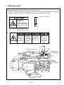
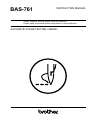
BAS-761
INSTRUCTION MANUAL
Please read this manual before using the machine.
Please keep this manual within easy reach for quick reference.
AUTOMATIC POCKET SETTER <JEANS>
Thank you very much for buying a BROTHER sewing machine. Before using your new machine, please
read the safety instructions below and the explanations given in the instruction manual.
With industrial sewing machines, it is normal to carry out work while positioned directly in front of moving
parts such as the needle and thread take-up lever, and consequently there is always a danger of injury that
can be caused by there parts. Follow the instructions from training personnel and instructors regarding safe
and correct operation before operating the machine so that you will know how to use the machine correctly.
SAFETY INSTRUCTIONS
z Safety indications and their meanings
This instruction manual and the indications and symbols that are used on the machine itself are provided in
order to ensure safe operation of this machine and to prevent accidents and injury to yourself or other
people. The meanings of these indications and symbols are given below.
Indications
DANGER
CAUTION
The instructions which follow this term indicate situations where failure to
follow the instructions will almost certainly result in death or severe injury.
The instructions which follow this term indicate situations where failure to
follow the instructions could cause injury when using the machine or physical
damage to equipment and surroundings.
Symbols
................. This symbol (
) indicates something that you should be careful of. The picture
inside the triangle indicates the nature of the caution that must be taken.
(For example, the symbol at left means "beware of injury".)
................. This symbol (
) indicates something that you must not do.
) indicates something that you must do. The picture inside the
................. This symbol (
circle indicates the nature of the thing that must be done.
(For example, the symbol at left means "you must make the ground connection".)
BAS-761
i
x Notes on safety
DANGER
Wait at least 5 minutes after turning off the power switch and disconnecting the power cord from
the wall outlet before opening the face plate of the control box.
Touching areas where high voltages are present can result in severe injury.
CAUTION
Environmental requirements
Use the sewing machine in an area which
is free from sources of strong electrical
noise such as high-frequency welders.
Sources of strong electrical noise may
cause problems with correct operation.
The ambient temperature should be within
the range of 5°C to 35°C during use.
Temperatures which are lower or higher
than this may cause problems with correct
operation.
Any fluctuations in the power supply voltage should be within ±10% of the rated
voltage for the machine.
Voltage fluctuations which are greater than
this may cause problems with correct operation.
The relative humidity should be within the
range of 45% to 85% during use, and no
dew formation should occur in any devices.
Excessively dry or humid environments and
dew formation may cause problems with
correct operation.
The power supply capacity should be
greater than the requirements for the sewing machine’s electrical consumption.
Insufficient power supply capacity may
cause problems with correct operation.
Avoid exposure to direct sunlight during use.
Exposure to direct sunlight may cause problems with correct operation.
In the event of an electrical storm, turn off
the power and disconnect the power cord
from the wall outlet.
Lightning may cause problems with correct
operation.
The pneumatic delivery capability should be
greater than the requirements for the sewing machine’s total air consumption.
Insufficient pneumatic delivery capability
may cause problems with correct operation.
ii
BAS-761
CAUTION
Installation
Be sure to wear protective goggles and
gloves when handling the lubricating oil and
grease, so that they do not get into your eyes
or onto your skin, otherwise inflammation can
result.
Furthermore, do not drink the oil or eat the
grease under any circumstances, as they can
cause vomiting and diarrhoea.
Keep the oil out of the reach of children.
Machine installation should only be carried
out by a qualified technician.
Contact your Brother dealer or a qualified
electrician for any electrical work that may
need to be done.
The sewing machine weights more than 400
kg. The installation should be carried out
by two or more people.
Avoid setting up the sewing machine near
sources of strong electrical noise such as
high-frequency welding equipment.
If this precaution is not taken, incorrect machine operation may re
Do not connect the power cord until installation is complete, otherwise the machine
may operate if the start switch is pressed
by mistake, which could result in injury.
Be sure to connect the ground. If the ground
connection is not secure, you run the risk
of receiving a serious electric shock.
Have two people present to hold the machine
head with both their hands when tilting it back
or returning it to its original position.
Sewing
Turn off the power switch at the following
times, otherwise the machine may operate if
the start switch is pressed by mistake, which
could result in injury.
This sewing machine should only be used
by operators who have received the
neccessary training in safe use beforehand.
The sewing machine should not be used
for any applications other than sewing.
• When replacing the needle
• When not using the machine and when leaving the machine unattended
Be sure to wear protective goggles when
using the machine.
Do not touch any of the moving parts or press
any objects against the machine while sewing, as this may result in personal injury or
damage to the machine.
If goggles are not worn, there is the danger
that if a needle breaks, parts of the broken
needle may enter your eyes and injury may
result.
If an error occurs in machine operation, or if
abnormal noises or smells are noticed, immediately turn off the power switch. Then
contact your nearese Brother dealer or a
qualified technician.
Attach all safety devices before using the
sewing machine.
If the machine is used without these devices
attached, injury may result.
If the machine develops a problem, contact
your nearest Brother dealer or a qualified
technician.
BAS-761
iii
CAUTION
Cleaning
Be sure to wear protective goggles and
gloves when handling the lubricating oil and
grease, so that they do not get into your eyes
or onto your skin otherwise inflammation can
result.
Furthermore, do not drink the oil or eat the
grease under any circumstances, as they can
cause vomiting and diarrhoea.
Keep the oil out of the reach of children.
Turn off the power switch before starting any
cleaning work, otherwise the machine may
operate if the start switch is pressed by mistake, which could result in injury.
Maintenance and inspection
If the power switch and air need to be left on
when carrying out some adjustment, be extremely careful to observe all safety precautions.
Maintenance and inspection of the sewing
machine should only be carried out by a
qualified technician.
Ask your Brother dealer or a qualified electrician to carry out any maintenance and
inspection of the electrical system.
Use only the proper replacement parts as
specified by Brother.
If any safety devices have been removed, be
absolutely sure to re-install them to their original positions and check that they operate
correctly before using the machine.
Turn off the power switch and disconnect
the power cord from the wall outlet at the
following times, otherwise the machine may
operate if the start switch is pressed by mistake, which could result in injury.
Any problems in machine operation which
result from unauthorized modifications to the
machine will not be covered by the warranty.
• When carrying out inspection, adjustment
and maintenance
Have two people present to hold the machine
head with both their hands when tilting it back
or returning it to its original position.
• When replacing consumable parts such
as the rotary hook and knife
Disconnect the air hoses from the air supply and wait for the needle on the pressure
gauge to drop to "0" before carrying out inspection, adjustment and repair of any parts
which use the pneumatic equipment.
iv
BAS-761
c Warning labels
★ The following warning labels appear on the sewing machine.
Please follow the instructions on the labels at all times when using the machine. If the labels have
been removed or are difficult to read, please contact your nearest Brother dealer.
1
3
Direction of operation
Moving parts
may cause injury.
Operate with safety devices.
Turn off main switch before
changing needle, cleaning
etc.
Safety devices: Thread take-up cover,
Guard bar, Belt cover, etc.
2
Hazardous voltage
will cause injury.
Hochspannung
verletzungsgefahr!
Turn off main
switch and wait 5
minutes before
opening this cover.
Bitte schalten sie den Eteindrel’interrupteur et
hauptschalter aus und attendre 5 minutes
warten sie 5 minuten, avantd’ ouvrir le capot
bevor sie diese
abdeckung ffnen.
Un voltage non adapt
provoque des blessures.
1
Thread take-up cover
Un voltaje inadecuado
puede provocar las
heridas.
Apagar el interruptor
principal y esperar 5
minutos antes de abrir
esta cubierta.
1
Belt cover
Guard bar
3
2
Guard bar
BAS-761
v
CONTENTS
1. Names of Machine Components ..............................................................................................................
1
2. Specifications .............................................................................................................................................
2
3. Installation ..................................................................................................................................................
3-1. Installation of the machine table .....................................................................................................
3-2. Removal of the fixing bolts from the machine ..............................................................................
3-3. Installation of the spool stand .........................................................................................................
3-4. Connection of the foot-switch connector .......................................................................................
3-5. Connection of the air hose ...............................................................................................................
3-6. Positioning of the front supporter ...................................................................................................
3-7. Installation positions for operation box and switch box ...............................................................
3-8. Installation of the folding group assembly ....................................................................................
3
3
4
4
5
5
5
6
7
4. Lubrication ..................................................................................................................................................
8
5. Correct operation .......................................................................................................................................
5-1. Installing the needle .........................................................................................................................
5-2. Upper threading ...............................................................................................................................
5-3. Bobbin case threading .....................................................................................................................
5-4. Bobbin thread winding ....................................................................................................................
5-5. Thread tension ..................................................................................................................................
9
9
9
10
11
12
6. Button functions ........................................................................................................................................
6-1. Operation box panel buttones .........................................................................................................
6-2. Switch box panel buttones ..............................................................................................................
6-3. Foot switch ........................................................................................................................................
6-4. RESTART buttones ...........................................................................................................................
13
13
16
17
17
7. Setting before sewing ...............................................................................................................................
7-1. Setting the folder mode ...................................................................................................................
7-2. Setting the sewing speed and the bar tacking speed ....................................................................
7-3. Setting the lower thread counter ....................................................................................................
7-4. Setting the piece counter .................................................................................................................
7-5. Setting the stacker roller feed amount ...........................................................................................
7-6. Setting the date and time ................................................................................................................
18
18
18
20
21
21
22
8. Preparation for sewing ..............................................................................................................................
23
9. Sewing ........................................................................................................................................................
9-1. Sewing with the folder in automatic mode ....................................................................................
9-2. Sewing with the folder in pattern matching mode ........................................................................
9-3. Sewing with the folder in label attachment mode .........................................................................
9-4. Sewing with the folder in step mode ..............................................................................................
9-5. Test feeding .......................................................................................................................................
9-6. Emergency stop ................................................................................................................................
25
25
26
27
28
29
30
10. Adjustments ...............................................................................................................................................
10-1. Needle-bar height adjustment .........................................................................................................
10-2. Needle and rotary hook timing ........................................................................................................
10-3. Presser foot height adjustment ........................................................................................................
10-4. Removal of the fixed knife and the movable knife .........................................................................
10-5. Stacker position adjustment ............................................................................................................
10-6. Sewing clamp assembly number selection ....................................................................................
31
31
32
32
33
34
35
11. Using the DIP switches ..............................................................................................................................
36
12. Table of error code .....................................................................................................................................
38
BAS-761
1. Names of Machine Components
1. Names of Machine Components
i
!0
y
o
u
!9
@0
!1
t
@1
r
!2
!4
!3
e
!5
w
!7
!6
!8
q
q Foot-switch
w Stacker
e Guard bar
r Feed roller
t Machine head
y Spool stand
u Top cover
i Control box
o Switch box
!0 Folding group assembly
!1 Mechanical valve
!2 RESTART buttons
!3 Front supporter
!4 Floppy drive
!5 Programmer
!6 Air unit valve
!7 Power switch
!8 Blower Motor
!9 2-Step thread tension device
@0 Thread breakage detector
@1 Pocket support
1
BAS-761
2. Specifications
2. Specifications
Applicable machine type
Lock stitch and special cross stitch sewing machine with automatic thread trimmer
Use
Sewing pockets on the various types of jeans
Cycle time
9 seconds approx. (depending on the pitch and rpm)
Sewing speed
500 – 4250rpm (9-step button selectable; limited by sewing condition)
Bar tacking speed
500 – 3500rpm (7-step button selectable; cannot exceed sewing speed)
250 (X) mm ⳯ 250 (Y) mm Standard (when not using retractable work clamp)
Sewing range
250 (X) mm ⳯ 200 (Y) mm For retractable work clamp
(restrictions may occur because of shape)
Sewing pitch
0.05 – 6.00mm
Needle racking width
at first bar tacking
Maximum of 3.5 mm
Cloth setting
Overlapping possible
Machine head drive
AC servo direct motor type
Machine body drive
X-axis for a clamp shift, Y-axis for a machine shift, AC servo motor (750W).
3.5-2HD inch floppy disk
Memory medium
64 patterns (Maximum of 1,000 stitches for each pattern)
Jig attaching/
detaching method
Air chuck; one-touch operation requiring less than 2 minutes
Stacker
Included (Stacking capacity 60 pieces)
Programmer
Included
Power source
3-phase 200V, 220V, 380V, 400V, 415V ( 900W)
Air pressure
0.44 – 0.54MPa
Machine dimensions
(W) 2.108mm, (L) 1.919mm, (H) 970mm
Weight
400kg
Upper-thread breakage
detector
Included
Label attachment device
Included (option)
BAS-761
2
3. Installation
3. Installation
CAUTION
Be sure to wear protective goggles and
gloves when handling the lubricating oil and
grease, so that they do not get into your eyes
or onto your skin, otherwise inflammation can
result. Furthermore, do not drink the oil or eat
the grease under any circumstances, as they
can cause vomiting and diarrhoea.
Keep the oil out of the reach of children.
Machine installation should only be carried
out by a qualified technician.
Contact your Brother dealer or a qualified
electrician for any electrical work that may
need to be done.
The sewing machine head weights more than
400 kg. The installation should be carried out
by two or more people.
Avoid setting up the sewing machine near
sources of strong electrical noise such as
high-frequency welding equipment.
If this precaution is not taken, incorrect machine operation may result.
Co not connect the power cord until installa
tion is complete, otherwise the machine may
operate if the foot switch is depressed by
mistake, which could result in injury.
Hold the machine head with both hands when
tilting it back or returning it to its original position. Furthermore, after tilting back the machine head, do not push the face plate side
or the pulley side from above, as this could
cause the machine head to topple over, which
may result in personal injury or damage to
the machine.
Be sure to connect the ground. If the ground
connection is not secure, you run the risk of
receiving a serious electric shock.
Do not place any objects on top of the top
cover, otherwise such objects may fall down
onto the machine.
If you need to put something on top of the top
cover, place it inside a box or similar to secure it so as to stop it from falling down.
Note:
¡ This sewing machine has a movable machine head and work clamp. Be careful not to place other objects within
the moving range of these parts.
¡ Supply power directly from a receptacle for the machine's exclusive use.
¡ Be sure to power off when installating.
3-1. Installation of the machine table
1.
Secure the level adjusters q so that the table top remain level.
2.
The table has eight level adjusters. If the table does not
sit well, loosen nuts w and turn the level adjusters q
to level the table.
Note:
There are eight adjusting points.
w
To move the machine, turn up adjusters q, and the table
can be moved on its machine body casters e.
q
e
3
BAS-761
3. Installation
3-2.Removal of the fixing bolts from the machine
The machine head and the sewing clamp arm are fixed with bolts to secure them during transportation.
q
Remove fixing bolt q on the machine head through the hole in the front cover.
Note:
¡ Save removed fixing bolts q future use.
¡ Before transporting the machine be sure to secure it with the fixing bolts.
3-3. Installation of the spool stand
Install the spool stand as shown in the illustration at left.
BAS-761
4
3. Installation
3-4. Connection of the foot-switch connector
Connect connector q securely.
q
3-5. Connection of the air hose
1.
Attach air hose q to air unit valve w.
2.
Move the upper cap of air unit valve w upward and adjust the air pressure to 0.49 MPa.
3.
After adjustment, move the cap downward and lock.
1.
Loosen bolts q and position front supporter w in the
most appropriate position.
2.
Tighten bolts q to secure the supporter w.
w
q
3-6. Positioning of the front supporter
q
5
w
BAS-761
3. Installation
3-7. Installation positions for operation box and switch box
Loosen the mounting bolts e for the operation box q
and switch box w, and move them in the direction of the
arrow to a position where they are comfortable to operate.
w
q
e
BAS-761
6
3. Installation
3-8. Installation of the folding group assembly
Before installation
¡ Apply air pressure.
¡ Turn on power switch q to return the machine to the home position.
¡ Turn valve switch w to OFF (lower) side and "E-820" will flash on the display.
o
e
i
y
u
!4
!3
!2
!1
t
w
r
!0
@1
q
1.
Install folding clamp assembly e onto folding base r.
2.
Attach multi-connector t.
3.
While pushing the folding clamp assembly e downwards with your hand, install the inner clamp assembly y to
the folding base r. For models with a label attachment device u, install the plug i of the label attachment device
u to the socket o.
At this time, set the label attachment device u so that it is in a ready condition on top of the inner clamp assembly.
(Refer to page 27.) If it is reversed, it will turn downward.
4.
Install center blade assembly !0 on folding base r.
5.
Install sewing clamp assembly !1 on sewing clamp assembly arm base !2.
6.
Install the multi-connector !4 and the dual sensor harness assembly !3.
7.
Set the valve switch w to ON (up position).
The "E-820" indication will disappear from the display panel and the panel will return to its previous condition.
8.
Move folding clamp assembly e, inner clamp assembly y, center blade assembly !0 and sewing clamp assembly
!1 back and forth, and right and left, to ensure they are secured.
7
BAS-761
4. Lubrication
4. Lubrication
Note:
Check for sufficient oil through oil gauge windows A and B on the machine head and the table.
If the oil amount is not sufficient, be sure to replenish it.
How to oil the machine head
Replenish the oil through oil port q.
How to oil the machine table
1 Move the machine head forward so that the lubrication hole e in the needle plate bracket RR w and the lubrication port r in the machine bed are aligned.
2 Apply oil to the lubrication port r in the machine bed through the lubricationhole e in the needle plate bracket
RR w.
Note:
Before initial operation of the machine or after a long interval, be sure to drip a few drops of oil onto the arrowed
lubrication point C.
How to drain oil from the machine body
Remove poly-oiler t and drain the oil.
Rotary hook lubrication control
Turn the rotary hook lubrication adjustment valve y to adjust the lubrication amount.
C
q
w
A
t
e
r
B
y
BAS-761
8
5. Correct operation
5. Correct operation
5-1. Installing the needle
Fully insert needle q, with its long groove to the left,
and secure it with screw w.
Note:
If the angle is incorrect, the needle an rotary hook
will lock when the needle bar is at its lowest position, so make sure that the needle and rotary hook
do not lock.
w
q
5-2. Upper threading
1.
Apply air pressure and turn on power switch.
2.
Press the FOLDER RESET button !9 to move the machine head back to the home position.
3.
Press FOOT button !1 and lower presser foot w.
4.
Pass the upper thread as illustrated below. After threading, be sure to press FOOT button !1 and lift presser foot w.
5.
After threading, turn the pulley and lift the needle-bar to the uppermost position.
!9
!1
N/thread
cooler assy
6
7
1
■ x2.4 rotary hook
■ x2.4 rotary hook
2
7
5
3
4
12
11
8
9
13
6
10
11
13
9
10
9
11
10
14
Leave about 50 mm of
thread end with the
thread take-up at its
highest position.
■ x1.7 rotary hook
BAS-761
9
15
10
16
w
50mm
9
14
■ x1.7 rotary hook
5. Correct operation
5-3. Bobbin case threading
■ Removal of the bobbin case
@0
!4
@1
1.
Press BOBBIN CHANGE button !4 and the machine will
move toward you and stop;
2.
Take out bobbin case q.
Replace the bobbin.
3.
If the RESTART buttones @0 are pressed after the RESET button @1 has been pressed, the machine head will
move back to the home position.
q
■ Removal of the bobbin
■ x2.4 rotary hook
Bobbin w can be removed when the latch is released.
■ x1.7 rotary hook
Latch
Latch
w
w
■ Bobbin case threading
■ x2.4 rotary hook
r
e
1.
Insert the bobbin into the bobbin case.
2.
Pass the thread through slot e and under adjustment
spring r.
3.
Pull the thread out from adjustment spring r.
■ x1.7 rotary hook
r
e
BAS-761
10
5. Correct operation
5-4. Bobbin thread winding
e
w
q
1.
Pass the bobbin thread from the spool stand as illustrated below.
2.
Wind the thread around the bobbin q as arrwed.
3.
Press lever w against the bobbin q.
4.
After completing bobbin q thread winding, cut the thread.
Note:
Check for any idle rotation of the bobbin q. The motor may overheat, if the bobbin q idles for a long time or if
it rotates without a bobbin. At this time, protector e will go up and the bobbin thread winding motor will not
start. If protector e is pressed after about 20 seconds has elapsed, bobbin theread winding can be restarted.
11
BAS-761
5. Correct operation
5-5. Thread tension
q
r
■ x2.4 rotary hook
Stitches when upper
thread tension is too low
e
Stitches when upper
thread tension is too high
Correct stitches
■ x2.4 rotary hook
■ x1.7 rotary hook
w
w
Low
Low
■ x1.7 rotary hook
e
High
High
1.
When the thread take-up lever is in the highest position after thread trimming, adjust the upper thread beyond the
needle eye so as it is 30 to 40 mm long, by turning tension nut q. (30 - 70 g is standard).
2.
Adjust the lower thread tension by turning tension regulating screw w. (40 - 60 g is standard.)
3.
Adjust the upper thread tension by turning tension nut e and r after lowering the presser foot.
Note:
Then adjust the tension 30 - 40 g by turning tension nut r.
Main adjust is performed by using tension nut e.
x2.4 rotary hook 150 - 200 g is standard.
x1.7 rotary hook 200 - 220 g is standard.
(
)
■ Thread take-up spring
■ x2.4 rotary hook
e
■ x1.7 rotary hook
e
30 - 60g
w
40 - 80g
q
q
5 - 8mm
1.
The standard height of the thread take-up spring q is when the stroke is 5 to 8 mm.In addition, the standard tension
in the thread take-up spring is 30 g to 60 g (x1.7 rotary hook 40 - 80g).
(The tension in the thread take-up spring when it is pulling the upper thread straight to the side at the point where
the spring starts to move.)
2.
To adjust the thread take-up spring height, loosen set-screw w and turn the whole unit of the tension regulator
assembly.
3.
To adjust the thread take-up spring force, insert a screwdriver tip into the groove of tension stud e and turn it as
much as is appropriate.
BAS-761
12
6. Button functions
6. Button functions
6-1. Operation box panel buttones
q
w
y
e
r
t
q LCD screen
Displays sewing information and error messages.
w FOLDING MODE button
This button is used to change the operating mode of the folder. Folder operating modes include automatic mode,
pattern matching mode, label attachment mode and step mode.
e LABEL button (LABEL indicator)
When the folder is in label attachment mode (for alternate label attachment) or in step mode, this button is used to
set whether label attachment operations are carried out or not. The indicator at the side of the button illuminates
and switches off each time the button is pressed.
When the indicator is illuminated, label attachment operations are carried out.
r STACKER button (STACKER indicator)
This button is used to set whether stacking operations are carried out after sewing. The indicator at the side of the
button illuminates and switches off each time the button is pressed.
When the indicator is illuminated, stacking operations are carried out.
t STEP button
When the folder is in step mode, it can be moved forward one step at a time each time this button is pressed, in
order to check the folding operation. If this button is pressed while the foot switch @3 is being depressed, the folder
will move in reverse.
y FLOPPY button
This button is used to store and retrieve sewing programs using a floppy disk.
13
BAS-761
6. Button functions
o
!2
u
!0
!3
i
!1
u SEWING SPEED button
This button is used to set the sewing speed and bar tacking speed. The sewing speed can be set in 9 steps from 500
to 4,250 rpm, and the bar tacking speed can be set in 7 steps from 500 to 3,500 rpm.
i COUNTER button
This button is used to set the lower thread counter, piece counter decrement (cleared when 0), stacker roller feed
amount, date and time. The setting item changes each time this button is pressed.
o THREAD MONITOR button (THREAD MONITOR indicator)
This button is used to set whether or not sewing stops automatically when an upper thread breakage occurs. The
indicator at the side of the button illuminates and switches off each time the button is pressed.
When the indicator is illuminated, upper thread breakages are detected.
!0 STEP BACK button
This button is used to resume sewing after an upper thread breakage occurs. The feed mechanism moves in reverse while this button is being pressed.
!1 FOOT button
This button is used to raise and lower the presser foot. The presser foot moves up and down each time this button
is pressed.
!2 TEST button (TEST indicator)
This button is used to carry out test feeding in order to check the number of stitches. Feeding is carried out without
the machine head operating. The indicator at the side of the button illuminates and switches off each time the button is pressed.
When the indicator is illuminated, test operation is being carried out. When the indicator is switched off, normal
sewing is carried out.
!3 FAST button
This button is used to increase the seed of step back or test operation. The feed mechanism moves faster while this
button is being pressed.
In addition, this button can also be used to set the piece counter to 0 (cleared).
BAS-761
14
6. Button functions
!7
!5
!8
!6
!4
!4 BOBBIN CHANGE button
If this button is pressed when changing the bobbin, the machine head can be moved forward to make bobbin changing
easier.
!5 CANCEL button
If this button is pressed during folder mode setting, while data is being saved to or read from a floppy disk, while
the sewing speed is being set or if the COUNTER button is being used to change a setting, the setting changes or
operations will be canceled and the setting mode will be exited.
!6 ENTER button
If this button is pressed during folder mode setting, while data is being saved to or read from a floppy disk, while
the sewing speed is being set or if the COUNTER button is being used to change a setting, the setting changes will
then become effective.
!7 Warning indicator
This indicator illuminates when an abnormality occurs or when the EMERGENCY STOP button has been pressed.
!8 Arrow keys
If this button is pressed during screen selection, folder mode setting, while data is being saved to or read from a
floppy disk, while the sewing speed is being set or if the COUNTER button is being used to change a setting, the
setting value or mode can be changed.
15
BAS-761
6. Button functions
6-2. Switch box panel buttones
!9
@0
@1
@2
!9 FOLDER RESET button (carries out positioning when the power is turned on)
This button is used to stop the folder while folding is in progress and to reset he folding condition.
When the button is pressed once, folding is stopped, and when it is pressed twice, the folder is reset, and the
workpiece and the pocket can then be set.
@0 START button
This button is used to resume sewing after an emergency stop has occurred during sewing or after an upper thread
breakage has occurred. It should be pressed after the RESET button has been pressed.
In addition, if an error has occurred, this button is used to continue operation after the cause of the error has been
eliminated.
@1 RESET button
This button is used to trim the thread after an emergency stop has occurred during sewing or after an upper thread
breakage has occurred.
In addition, if an error has occurred, this button is used to clear the error status after the cause of the error has been
eliminated.
@2 EMERGENCY STOP button
This button is used to stop all operations.
BAS-761
16
6. Button functions
6-3. Foot switch
@3
Foot switch @3
When the folder is in automatic mode, this switch is used to operate the vacuum system.
When the folder is in pattern matching mode, this switch is used to raise and lower the folder table to carry out
pattern matching.
When the folder is in label attachment mode, this switch is used to carry out label attaching.
When the folder is in step mode, this switch operates in the same way as in label attachment mode or automatic
mode, depending on whether label attachment operations are being carried out or not.
6-4. RESTART buttones
@4
RESTART buttones @4
When these buttones are pressed simultaneously, the folder starts operating.
17
BAS-761
7. Settings before sewing
7. Settings before sewing
Press FOLDER RESET SW
to start searching for home
position.
1.
Turn on the air pressure and then turn on the power
switch.
The screen shown at left will be displayed on the panel.
2.
Press the FOLDER RESET button !9. The machine head
will move to the home position and then stop in the
standby condition.
1.
Press the FOLDING MODE button w. Screen 1 will then
be displayed.
2.
Press the arrow keys !8 to select the mode.
7-1. Setting the folder mode
FOLDING MODE
AUTO
PATTERN
LABEL
STEP
Screen 1
Note
Background color of the selected mode
turns reverse on display.
If the CANCEL button !5 or FOLDING MODE button w
is pressed once more, the mode will not be changed
and the screen will return to the original display.
3.
Press the ENTER button !6. The new mode will be set
and the screen will return to the original display.
7-2. Setting the sewing speed and the bar tacking speed
¡ These settings can be made when the machine head is at the standby position, while the bobbin is being replaced
and while sewing is stopped.
¡ The bar tacking speed cannot be greater than the sewing speed. If the bar tacking speed is set to a faster speed
than the sewing speed, the bar tacking speed will become the same as the sewing speed when sewing is actually
carried out.
Change sewing speed.
1.
Press the SEWING SPEED button u. Screen 2-1 will
then be displayed.
2.
Press the arrow keys !8 to select the desired sewing
speed.
SEWING SPEED 4000 rpm
Screen 2-1
The sewing speed can be set in 9 steps from 500 to
4,250 rpm.
* If the CANCEL button !5 is pressed, the sewing speed
will not be changed and the screen will return to the
original display.
BAS-761
18
7. Settings before sewing
* If the SEWING SPEED button u is pressed once
more, the sewing speed will not be changed, and
screen 2-2 for changing the bar tacking speed will be
displayed.
Change tack speed.
TACK SPEED
3000 rpm
Screen 2-2
3.
Press the ENTER button !6. The sewing speed will be
changed to the new setting, and screen 2-2 for changing the bar tacking speed will be displayed.
4.
Press the arrow keys !8 to select the desired bar tacking speed.
The bar tacking speed can be set in 7 steps from 500
to 3,500 rpm.
* If the CANCEL button !5 or SEWING SPEED button
u is pressed, the bar tacking speed will not be
changed and the screen will return to the original
display.
Change sewing speed.
5.
Press the ENTER button !6.
The bar tacking speed will be changed to the new setting, and the screen will return to the initial display.
SEWING SPEED 4000 rpm
Screen 2-1
¡ The maximum number of stitches is limited by the
sewing pitch in the sewing data as shown in the table
below.
Pitch
– 3.5mm
19
BAS-761
Max. sewing speed
4250rpm
3.55 – 4.5mm
3500rpm
4.55 – 5.0mm
3000rpm
5.05 – 6.0mm
2500rpm
7. Settings before sewing
7-3. Setting the lower thread counter
¡ The lower thread counter determines how many workpieces can be produced according to the amount of lower
thread which has been wound inside the bobbin case.
¡ This setting can be made when the machine head is at the standby position and while the bobbin is being replaced.
Change bobbin counter.
BOBBIN COUNTER
Screen 3
1.
Press the COUNTER button i once. Screen 3 will then
be displayed.
2.
Use the arrow keys !8 to change the counter setting.
Use the [ ] and [ ] keys to select the column, and
use the [ ] and [ ] keys to change the digit.
60
If the CANCEL button !5 is pressed, the lower thread
counter will not be changed and the screen will return
to the original display.
3.
Press the ENTER button !6.
The lower thread counter will be changed to the new
setting, and the screen will return to the initial display.
■ Replacing the lower thread
When the value for the lower thread counter becomes "0", the machine head automatically moves forward. After the
bobbin is replaced and the reset operation is carried out, the value for the counter returns to the setting value.
NOTE:
If the BOBBIN CHANGE button is pressed manually, and the above operation is carried out, the lower thread counter
will not return to the setting value. In addition, if the value is set to "0", the lower thread counter will not operate.
BAS-761
20
7. Settings before sewing
7-4. Setting the piece counter
¡ This setting can be made when the machine head is at the standby position and while the bobbin is being replaced.
¡ The piece counter can be set to "0" (reset), or it can be decremented by 1, It cannot be incremented.
Change piece counter.
PIECE COUNTER
1.
Press the COUNTER button i twice. Screen 4 will then
be displayed.
2.
Press the FAST button !3 to reset the piece counter to
"0".
1234
Screen 4
Press the arrow key !8 once to decrement the piece
counter by 1.
* If the CANCEL button !5 is pressed, the piece counter
value will not be changed and the screen will return
to the original display.
3.
Press the ENTER button !6.
The piece counter will be changed to the new setting,
and the screen will return to the initial display.
7-5. Setting the stacker roller feed amount
¡ This setting can be made when the machine head is at the standby position and while the bobbin is being replaced.
Change stack feed length.
STACK FEED LENGTH
1.
Press the COUNTER button i three times. Screen 5 will
then be displayed.
2.
Press the arrow keys !8 to select the desired stacker
roller feed amount.
250 mm
Screen 5
The setting can be made in 9 steps from 0 mm to 400
mm, with each step being 50 mm.
3.
21
BAS-761
Press the ENTER button !6.
The stacker roller feed amount will be changed to the
new setting, and the screen will return to the initial
display.
7. Settings before sewing
7-6. Setting the date and time
This setting can be made when the machine head is at the standby position and while the bobbin is being replaced.
Change date.
DATE
1.
Press the COUNTER button i four times. Screen 6-1
will then be displayed.
2.
Press the [ ] and [ ] arrow keys !8 to select the year,
month or day, and press the [ ] and [ ] arrow keys
!8 to change the setting for the selected item.
1998/10/1
Screen 6-1
* If the CANCEL button !5 is pressed, the date will not
be changed and the screen will return to the original display.
Change time.
TIME
* If the COUNTER button i is pressed, the date will
not be changed and the screen will change to screen
6-2 for setting the time.
15:30:00
Screen 6-2
3.
Press the ENTER button !6.
The date will be changed to the new setting, and the
screen will change to screen 6-2 for setting the time.
4.
Press the [ ] and [ ] arrow keys !8 to select the hour
or minutes, and press the [ ] and [ ] arrow keys !88
to change the setting for the selected item.
* If the CANCEL button !5 or COUNTER button i is
pressed, the time will not be changed and the screen
will return to the original display.
5.
Press the ENTER button !6.
The time will be changed to the new setting, and the
screen will return to the initial display.
The seconds will be reset to "0" at the point where the
ENTER button !6 is pressed.
BAS-761
22
8. Preparation for sewing
8. Preparation for sewing
Press FOLDER RESET SW
1.
Apply air pressure and turn on power switch.
Screen 7 will then be displayed on the panel.
to start searching for home
position.
2.
Press the FOLDER RESET button !9.
The machine head will move to the home position and
then stop in the standby condition.
3.
Select the normal display screen.
The screen displayed will change in the following order each time the arrow key !8 is pressed.
Screen 8-1→ screen 8-2→ ...
It will change in the following order each time the arrow key !8 is pressed.
Screen 8-5 → screen 8-4 → ...
Screen 7
1997/11/5 19:36:50
FOLDING MODE
PROGRAM NUMBER
SEWING SPEED
rpm
Screen 8-1
1997/11/5 19:36:50
FOLDING MODE
PIECE COUNTER
BOBBIN COUNTER
Screen 8-2
1997/11/5 19:36:50
PROGRAM NUMBER
PIECE COUNTER
BOBBIN COUNTER
Screen 8-3
1997/11/5 19:36:50
SEWING SPEED
rpm
PIECE COUNTER
BOBBIN COUNTER
Screen 8-4
1997/11/5 19:36:50
SEWING CLAMP NUMBER
STACK FEED LENGTH
mm
Screen 8-5
23
BAS-761
8. Preparation for sewing
4.
Insert a floppy disk.
Note:
Insert a floppy disk straight into the slot.
The label side of the disk must face the front.
5.
Press the FLOPPY button y. Screen 9 will then be displayed.
Read sewing data.
PROGRAM NUMBER
Use the arrow keys !8 to select the same number as
the work clamp assembly. Then use the [ ] and [ ]
arrow keys !8 to select the column, and use the [ ]
and [ ] arrow keys !8 to change the values.
__
Screen 9
Refer to page 35 for details on setting the work clamp
assembly number.
6.
Press the ENTER button !6. The sewing data which corresponds to the number specified will then be read from the
floppy disk.
* The sewing data will be backed up even when the power is turned off. The number for the backed-up sewing
data can be checked by viewing the program number on screen 8-1 or screen 8-3.
1997/11/5 19:36:50
PROGRAM NUMBER
PIECE COUNTER
BOBBIN COUNTER
Screen 8-3
NOTE:
If there is no backup data, the display will be blank.
7.
Check that the THREAD MONITOR indicator o is illuminated. If it is switched off, press the THREAD MONITOR button o until the indicator is illuminated.
NOTE:
If the indicator is switched off, the machine head will not stop automatically if an upper thread breakage is detected during sewing.
8.
If starting to sew with a new bobbin, set the lower thread counter by following the steps given on page 20.
9.
Follow the steps given on page 21 to reset the piece counter to "0" if required.
10. Follow the steps given on page 18 to set the sewing speed if required.
11. If the STACKER indicator r is switched off, press the STACKER button r so that the indicator illuminates.
NOTE:
If the indicator is switched off, the workpieces will not be stacked after they have been sewn.
BAS-761
24
9. Sewing
9. Sewing
9-1. Sewing with the folder in automatic mode
w
r
e
q
@3
@4
1.
Turn on the air pressure and then turn on the power switch.
The following screen will be displayed on the panel.
Press FOLDER RESET SW
to start searching for home
position.
2.
Press the FOLDER RESET button !9.
The machine head will move to the home position and then
stop in the standby condition.
3.
Set the folder mode to automatic mode.
NOTE:
Refer to page 18 for details on how to set the folder mode.
4.
Press the STACKER button r so that the STACKER indicator is illuminated.
5.
Place the workpiece w under the gauge assembly q. (*1)
6. Depress the foot switch @3. The vacuum system will start operating to hold the workpiece w in place.
NOTE:
If the foot switch @3 is depressed once more, the vacuum system will turn off while the foot switch @3 is being
depressed, allowing the workpiece to be positioned more easily.
7.
Place the pocket material e on top of the gauge assembly q.
8.
Press the RESTART buttones @4 simultaneously.
The pocket material e will be folded by the folder and the workpiece w and the pocket material e will then be
moved to the machine head and sewing will start. (*2)
9.
Once sewing is finished, the stacker will operate and the workpiece w will be stacked. The machine head and the
work clamp will then return to the standby positions.
*1
*2
25
If DIP switch D-1 has been set to ON, the gauge assembly q will retract. The gauge assembly q moves
forward at the same time the vacuum system starts operating when the foot switch @3 is depressed.
If DIP switch A-1 has been set to ON, operation stops momentarily after folding has been completed so that
the folding can be checked. When the RESTART buttones @4 are pressed again simultaneously, operation
continues as before.
BAS-761
9. Sewing
9-2. Sewing with the folder in pattern matching mode
r
w
e
q
@3
@4
1.
Turn on the air pressure and then turn on the power switch.
The following screen will be displayed on the panel.
Press FOLDER RESET SW
to start searching for home
position.
2.
Press the FOLDER RESET button !9. The machine head will
move to the home position and then stop in the standby
condition.
3.
Set the folder mode to pattern matching mode.
NOTE:
Refer to page 18 for details on how to set the folder mode.
4.
Press the STACKER button r so that the STACKER indicator is illuminated.
5.
Place the workpiece w under the gauge assembly q. (*1)
6.
Depress the foot switch @3. The vacuum system will start operating to hold the workpiece w in place.
7.
Place the pocket material e on top of the gauge assembly q.
8.
When the foot switch @3 is released from being depressed, the gauge assembly q will drop to its lowest position.
If the pattern on the pocket material e is not aligned with the pattern on the workpiece w at this time, depress the
foot switch @3 once more. The vacuum system will turn off and the gauge assembly q will move one step upward
so that the patterns can be matched.
9.
Press the RESTART buttones @4 simultaneously.
The pocket material e will be folded by the folder and the workpiece w and the pocket material e will then be
moved to the machine head and sewing will start. (*2)
10. Once sewing is finished, the stacker will operate and the workpiece w will be stacked. The machine head and the
work clamp will then return to the standby positions.
*1
*2
If DIP switch D-1 has been set to ON, the gauge assembly q will retract. The gauge assembly q moves
forward at the same time the vacuum system starts operating when the foot switch @3 is depressed.
If DIP switch A-1 has been set to ON, operation stops momentarily after folding has been completed so that
the folding can be checked. When the RESTART buttones @4 are pressed again simultaneously, operation
continues as before.
BAS-761
26
9. Sewing
9-3. Sewing with the folder in label attachment mode
¡ Two types of label attachment mode can be used: when DIP switch D-2 is set to OFF, alternate label attachment
is carried out, and when DIP switch D-2 is set to ON, continuous label attachment is carried out.
¡ With alternate label attachment, the folder switches alternately between label attachment mode and automatic
mode once for each sewing operation. During label attachment mode, the LABEL indicator e illuminates. If you
would like to switch over the modes, press the LABEL button e.
¡ With continuous label attachment, label attachment mode is active all the time. (The LABEL indicator e will remain illuminated.)
r
u
e
t
q
y
o
i
@3
@4
1. Set the folder mode to label attachment mode.
NOTE:
Refer to page 18 for details on how to set the folder mode.
2.
Press the STACKER button r so that the STACKER indicator is illuminated.
3.
Place the workpiece t under the gauge assembly q. (*1)
4.
Depress the foot switch @3. The vacuum system will start operating to hold the workpiece t in place.
5.
Place the pocket material y on top of the gauge assembly q.
6.
Depress the foot switch @3, and hold it in that condition. The intermediate work clamp u will be set down on top of
the gauge assembly q and label setting will be possible.
Place the label i into the clamp o of the label attacher.
After setting the label i in place, release the foot switch @3. The clamp o of the label attacher will clamp the label
i and then rotate to the folding position.
If you would like to reclamp the label i, depress the foot switch @3 once more and keep it depressed. The label can
then be reset.
7.
Press the RESTART buttones @4 simultaneously.
The pocket material y will be folded by the folder and the workpiece t and the pocket material y will then be
moved to the machine head and sewing will start. (*2)
8.
Once sewing is finished, the stacker will operate and the workpiece w will be stacked. The machine head and the
work clamp will then return to the standby positions.
* If the LABEL indicator e is switched off, it means that automatic mode is active.
*1
*2
27
If DIP switch D-1 has been set to ON, the gauge assembly q will retract. The gauge assembly q moves
forward at the same time the vacuum system starts operating when the foot switch @3 is depressed.
If DIP switch A-1 has been set to ON, operation stops momentarily after folding has been completed so that
the folding can be checked. When the RESTART buttones @4 are pressed again simultaneously, operation
continues as before.
BAS-761
9. Sewing
9-4. Sewing with the folder in step mode
¡ In step mode, the folder operates in a step-by-step manner, so that checking can be carried out during folding.
¡ If he LABEL indicator e is switched off, automatic mode is followed during step mode operation. If the LABEL
indicator e is illuminated, label attachment mode is followed.
NOTE:
Selecting the mode to be followed is carried out by using the LABEL button e.
Press FOLDER RESET SW
to start searching for home
position.
q
1.
Turn on the air pressure and then turn on the power
switch.
The screen shown at left will be displayed on the
panel.
2.
Press the FOLDER RESET button !9. The machine
head will move to the home position and then stop
in the standby condition.
3.
Set the folder to step mode.
NOTE:
Refer to page 18 for details on how to set the folder
mode.
e
4.
Press the STACKER button r so that the STACKER
indicator is illuminated.
5.
Place the workpiece q under the gauge assembly q.
(*1)
6.
Depress the foot switch @3. The vacuum system will
start operating to hold the workpiece q in place.
7.
Place the pocket material e on top of the gauge assembly w.
w
@3
8.
The folder operates one step at a time each time the STEP button t is pressed.
9.
If you continue to press the STEP button t after folding has been completed, the work clamp assembly will move
to the folder side and operation will continue from transporting to sewing.
NOTE:
At any point up until the folder is released, the folder can be moved in reverse by depressing and holding the foot
switch @3 while pressing the STEP button t.
*1
If DIP switch D-1 has been set to ON, the gauge assembly w will retract. The gauge assembly w moves
forward at the same time the vacuum system starts operating when the foot switch @3 is depressed.
BAS-761
28
9. Sewing
9-5. Test feeding
Test feeding should always be carried out a new program is created or when changes are made to existing data.
NOTE:
Check that the needle does not touch the work clamp.
1.
Carry out the sewing preparation as far as step 6.
2.
Press the TEST button !2 and check that the TEST indicator is illuminated.
3.
Operate the folder in the same way as for normal sewing. The folder can be set to any mode.
4.
After folding is complete, the work clamp assembly will transport the workpiece to the machine head, and feeding
will then continue stitch by stitch according to the program contents without the machine head motor operating.
If the FAST button !3 is pressed during feeding, the feeding speed will become faster for as long as the FEED button
!3 is being pressed.
5.
If the TEST button !2 is pressed during the above feeding operation, feeding will stop and the TEST indicator !2 will
switch off.
At this time:
¡ If the TEST button !2 is pressed once more, the TEST indicator !2 will illuminate and feeding will start again.
¡ If the STEP BACK button !0 is pressed, the feeding will be carried out in reverse for as long as the STEP BACK
button !0 is being pressed. If it is pressed together with the FAST button !3, the feeding speed will become faster.
¡ If the RESTART buttones @0 are pressed without pressing the TEST button !2, sewing will start from the current
stopping position.
6.
29
Once feeding is complete, the machine head and the work clamp will then return to the standby positions.
BAS-761
9. Sewing
9-6. Emergency stop
To stop the machine during sewing
If you would like to stop the machine head during sewing, press the EMERGENCY STOP button @2. The machine head
will stop and the error message "E-801" will appear on the panel screen.
If the RESET button @1 is then pressed, the thread will be trimmed and the screen will return to the normal display.
To continue sewing
1.
Press the STEP BACK button !0 to return to the place from where you would like sewing to resume.
2.
Press the RESTART buttones @0 to start sewing again.
To interrupt sewing and return to the standby position
1.
Press the EMERGENCY STOP button @2 during sewing to stop the sewing machine. Then press the RESET switch @1
so that a normal screen is displayed, and press the EMERGENCY STOP button @2 once more. The error message
“E-801” will appear on the panel display. Press the EMERGENCY STOP button @2 once more. The error message "E801" will appear on the panel display.
2.
Press the RESET button @1. Screen 7 (Refer to page 23) will be displayed.
3.
Press the FOLDER RESET button !9. The machine head will return to the home position and stop in standby mode.
If a thread breakage occurs during sewing
If the thread breaks during sewing, the machine head wills top and error message "E-520" will appear on the panel display. When the RESET button @1 is pressed, thread trimming will be carried out, and the screen will return to the normal
display.
1. Thread the upper thread and move the thread take-up lever to its highest position.
2.
Press the STEP BACK button !0 to return to the place from where you would like sewing to resume.
3.
Press the RESTART buttones @0 to start sewing again.
BAS-761
30
10. Adjustments
10. Adjustments
CAUTION
Maintenance and inspection of the sewing
machine should only be carried out by a qualified technician.
Ask your Brother dealer or a qualified electrician to carry out any maintenance and inspection of the electrical system.
Turn off the power switch and disconnect the
power cord from the wall outlet at the following times, otherwise the machine may operate if the foot switch is depressed by mistake,
which could result in injury.
¡ When carrying out inspection, adjustment
and maintenance
¡ When replacing consumable parts such as
the rotary hook and knife
Hold the machine head with both hands
when tilting it back or returning it to its original position. Furthermore, after tilting back
the machine head, do not push the face plate
side or the pulley side from above, as this
could cause the machine head to topple over,
which may result in personal injury or damage to the machine.
If the power switch needs to be left on when
carrying out some adjustment, be extremely
careful to observe all safety precautions.
If any safety devices have been removed, be
absolutely sure to re-install them to their
original positions and check that they operate correctly before using the machine.
Note:
¡ Turn the power switch off if the adjustment does not need power to be supplied.
¡ If the power switch is turned on, take sufficient safety measures, such as to make E-800 (emergency stop) come
on in the manual mode.
10-1. Needle-bar height adjustment
o
w
e
q
BA
S7
61
2.4
1
r
Gauge 1
(x2.4 rotary
hook)
2
!0
!2
i
u
t
!1
q
y
When needle-bar q is at its lowest position, the lower end of needle-bar q must be matched the end of gauge 1.
1.
Remove flat-head screws w and then needle plate RR e and needle plate RL r.
2.
Loosen the screw t and then remove the needle y.
3.
Remove screw u and then presser foot assembly i.
4.
Remove screws o and then bottom-plunger !0.
5.
Remove oil cap !1 and screw !2, adjust the height by moving needle-bar q up and down.
31
BAS-761
10. Adjustments
10-2. Needle and rotary hook timing
■ x1.7 rotary hook
q
e
w
0 – 0.05mm
• for x1.7 rotary hook 1.8mm
• for x2.4 rotary hook 2.4mm
Gauge
r
2
76
1
1.7
• for x1.7 rotary hook 1.8mm
• for x2.4 rotary hook 1.2mm
1
BA
S
¡ After needle-bar q is raised from its lowest position, rotary hook point w must be aligned with the center of needle
e when the lower end of needle-bar q is matched the end of gauge 2.
¡ If rotary hook point w is not aligned with the center of needle e, loosen screws r and align the center of needle e
with rotary hook point w.
¡ Timing gauge
If there is a recess at the right edge of the bed, use gauge A; if there is none, use gauge B.
A With recess
BA
S7
6
1.1
7
B Without recess
BA
1
M
S7
6
2.1
4
1
2
2
x1.7 rotary hook
(S52232-000)
S5
P1
.2
1
2
Recess
47
42
00
0
x2.4 rotary hook
(S54742-000)
x2.4 rotary hook
(S51288-000)
10-3. Presser foot height adjustment
e
w
37mm
t
r
y
q
for x2.4 rotary hook 16.5mm
for x1.7 rotary hook 14.5mm
The standard presser foot height is 16.5 mm (for x2.4 rotary hook) or 14.5mm (for x1.7 rotary hook) above the needle
plate when the presser foot q is raised.
1.
Loosen nut w and then pressure adjusting screw e.
2.
Press the FOOT button to raise working presser foot q.
3.
Remove face-plate oil cap r and loosen screw t. Adjust the height by moving presser bar y.
The standard spring tension for the sewing clamp spring is obtained when the height of the presser foot adjustment
screw is 37 mm.
Check that the point of the needle does not protrude below the presser foot when the needle is at its highest position.
BAS-761
32
10. Adjustments
10-4. Removal of the fixed knife and the movable knife
Note:
Turn off the power switch.
■ Removal of the fixed knife
Notch
q
w
Belows rail
r
e
u
r
t
i
y
1.
Remove flat-head screws q and then needle plate RR w and needle plate RL e.
2. Remove clamping screws r and then tilt the machine head.
NOTE:
At this time, adjust the position of the machine head so that it is aligned with the notch in the bellows rail.
3.
Remove clamping bolt t and then bobbin case holder position bracket y.
4. Remove flat-head screw u and then fixed knife i.
¡ When the fixed knife i becomes blunt, sharpen it as illustrated at right.
■ Removal of the movable knife
q
r
e
t
w
y
t
y
u
1.
Remove flat-head screws q and then needle plate RR w.
2.
Remove clamping screw e and then presser foot assembly r.
3.
Turn the pulley and stop the needle bar at its highest position.
4.
Remove screw t and then needle y.
5.
Push thread trimming rod t in the arrowed direction and stop where flat-head screws y can be seen.
6. Remove flat-head screws y and then movable knife u.
Note:
To reassemble, reverse the above procedures.
33
BAS-761
10. Adjustments
10-5. Stacker position adjustment
1.
Loosen the four bolts w and adjust the height of the
stacker base q so that the workpieces stack neatly onto
the stacker base q.
2.
Loosen the two bolts e, and then adjust the vertical
position of the stacker base q so that the workpieces
stack neatly onto the stacker base q.
3.
Loosen the bolt r and adjust the height of the inner
work clamp bart.
4.
Loosen the bolt y and adjust the height of the outer
work clamp baru.
BAS-761
34
w
t
q
e
u
y
r
10. Adjustments
10-6. Sewing clamp assembly number selection
Clamping screw 3 ⳯ 5
Spring washer
Slit D
Slit C
Sewing clamp assembly
¡ Attach slit C and Slit D to the sewing clamp assembly by a clamping screw and a spring washer.
See the table below for the sewing clamp assembly numbers.
■ Sewing clamp assembly number
NOTE:
¡ For retractable clamps, set jumpers 0 to 31.
¡ For single clamps, set jumpers 32 to 63.
35
0
1
2
3
4
5
6
7
8
9
10
11
™™
™™
™™
™™
™™
¡¡
™™
¡¡
™™
™™
¡¡
¡¡
¡¡
™™
™™
¡¡
™™
¡¡
¡¡
¡¡
™™
¡¡
¡¡
¡¡
™™
™™
¡¡
™™
™™
¡¡
™™
¡¡
¡¡
™™
¡¡
¡¡
12
13
14
15
16
17
18
19
20
21
22
23
¡¡
™™
¡¡
¡¡
™™
¡¡
¡¡
¡¡
¡¡
¡¡
¡¡
¡¡
™™
¡¡
™™
™™
¡¡
¡¡
™™
¡¡
™™
™™
¡¡
¡¡
¡¡
¡¡
¡™
¡¡
¡¡
¡¡
¡¡
¡¡
™™
¡¡
¡¡
¡¡
24
25
26
27
28
29
30
31
™™
¡¡
¡¡
™™
¡¡
¡¡
™™
¡¡
¡¡
™™
¡¡
¡¡
¡¡
¡¡
¡¡
¡¡
¡¡
¡¡
¡¡
¡¡
¡¡
¡¡
¡¡
¡¡
32
33
34
35
36
37
38
39
40
41
42
43
¡¡
™™
™™
¡¡
™™
¡¡
¡¡
¡¡
™™
¡¡
¡¡
¡¡
¡¡
™™
™™
¡¡
™™
¡¡
¡¡
¡¡
™™
¡¡
¡¡
¡¡
¡¡
™™
¡¡
¡¡
™™
¡¡
¡¡
¡¡
¡¡
¡¡
¡¡
¡¡
44
45
46
47
48
49
50
51
52
53
54
55
¡¡
™™
¡¡
¡¡
™™
¡¡
¡¡
¡¡
¡¡
¡¡
¡¡
¡¡
¡¡
¡¡
™™
¡¡
¡¡
¡¡
¡¡
¡¡
™™
¡¡
¡¡
¡¡
¡¡
¡¡
™™
¡¡
¡¡
¡¡
¡¡
¡¡
™™
¡¡
¡¡
¡¡
56
57
58
59
60
61
62
63
¡¡
¡¡
¡¡
¡¡
¡¡
¡¡
¡¡
¡¡
¡¡
¡¡
¡¡
¡¡
¡¡
¡¡
¡¡
¡¡
¡¡
¡¡
¡¡
¡¡
¡¡
¡¡
¡¡
¡¡
BAS-761
11. Using the DIP switches
11. Using the DIP switches
DANGER
Wait at least 5 minutes after turning off the power switch and disconnecting the power cord from the wall
outlet before opening the face plate of the control box. Touching areas where high voltages are present can
result in severe injury.
Note:
¡ Always be sure to turn the power OFF when changing the settings of the DIP switches.
¡ The functions of the DIP switches are subject to changes without notification.
¡ If DIP switches B-1 to B-6 are ON, be sure to check the cylinder movement and data version thoroughly. In some
cases a peculiar error may be displayed.
■ DIP switch positions
DIP switch D
DIP switch B
DIP switch A
DIP switch E
DIP switch C
■ Functions of operation panel DIP switches
¡ DIP switch A
Functions when ON
No.
1
In automatic, pattern matching and label attachment modes, the work clamp stops momentarily before
feeding to the home position.
2
Low feeding speed (Machine head → Folder)
3
Low feeding speed (Folder → Machine head)
4
Not available (Should be set to OFF)
5
Not available (Should be set to OFF)
Not available (Should be set to OFF)
6
7
After the power is turned on, three pockets are sewn at 3,000 rpm.
8
Machine head operation check, stacker operation check
■ Functions of DIP switches on main circuit board
¡ DIP switch B
Functions when ON
No.
1
Mismatches between folder numbers and program numbers are ignored
2
Clamp vertical sensor is ignored
3
Needle racking cylinder sensor is ignored
4
Double cylinder sensor is ignored
5
24 V/36 V power supply voltage check is ignored
6
Single and double clamp data check is ignored
7
Not available (Should be set to OFF)
8
Not available (Should be set to OFF)
BAS-761
36
11. Using the DIP switches
¡ DIP switch C
No.
Functions when ON
1
7 stitches counted before upper thread breakage is detected
OFF: 3 stitches counted before upper thread breakage is detected
2
After sewing, the work clamp and machine head return to the previous standby position, even if folding
has been completed.
3
Movement to the feed destination occurs immediately when the program data requires it.
4
After sewing, the timer starts 0.2 seconds after the work clamp is raised.
5
Not available (Should be set to OFF)
6
Not available (Should be set to OFF)
7
Not available (Should be set to OFF)
8
Not available (Should be set to OFF)
¡ DIP switch D
No.
Functions when ON
1
The gauge standby position is always forward.
When OFF: The gauge standby position is at the back.
2
Continuous label attachment mode
When OFF: Alternate label attachment mode
3
Folder operates at low speed
4
Folder procedure changes
5
Folding is released when base 1.5 is raised
6
Not available (Should be set to OFF)
7
Not available (Should be set to OFF)
8
Not available (Should be set to OFF)
¡ DIP switch E
37
No.
Functions when ON
1
Not available (Should be set to OFF)
2
Not available (Should be set to OFF)
3
Not available (Should be set to OFF)
4
Not available (Should be set to OFF)
5
Not available (Should be set to OFF)
6
Not available (Should be set to OFF)
7
Not available (Should be set to OFF)
8
Not available (Should be set to OFF)
BAS-761
12. Table of error code
12. Table of error code
¡ If an error occurs which cannot be reset, turn off the power momentarily and eliminate the cause of the problem.
¡ If an error occurs which can be reset, eliminate the cause of the problem and then press the RESET button.
Contents
Error code
Reset
E – 500
Abnormal rise in 24 V power supply voltage (exceeds +20% of rating)
No
E – 501
Abnormal drop in 24 V power supply voltage (exceeds -20% of rating)
No
E – 502
Abnormal rise in 36 V power supply voltage (exceeds +20% of rating)
No
E – 503
Abnormal drop in 36 V power supply voltage (exceeds -20% of rating)
No
E – 504
Abnormal rise in primary voltage (exceeds +20% of rating)
No
E – 505
Abnormal drop in primary voltage (exceeds -20% of rating)
No
E – 510
Needle bar is not at its highest position at the start of positioning.
Yes
E – 511
Needle bar is not at its highest position at the start of sewing.
Yes
E – 512
Needle bar is not at its highest position during test feeding.
Yes
E – 513
Needle bar is not at its highest position during programming.
Yes
E – 520
Upper thread breakage error
Yes
E – 530
Model and sewing program number do not match.
Yes
E – 535
Retractable are for double (0 to 31) but data does not contain a double switching
command.
Yes
E – 536
Model numbers are for single (32 to 63) but data does not contain a single
switching command.
Yes
E – 540
Machine head synchronization sensor error or machine head motor error
Yes
E – 550
Needle up stop error
No
E – 560
Presser foot cylinder malfunction or sensor malfunction
No
E – 570
Double sensor error
No
E – 580
Needle racking cylinder malfunction or sensor malfunction
No
E – 600
Machine started with no sewing data
No
E – 700
Error occurred when reading from floppy disk
Yes
E – 701
Error occurred when writing to floppy disk
Yes
E – 710
No sewing data for number specified
Yes
E – 711
Data writing carried out with no sewing data
Yes
E – 720
No disk in floppy disk drive
Yes
E – 730
Floppy disk is write-protected
Yes
E – 740
Insufficient free space on floppy disk
Yes
E – 750
Floppy disk cannot be formatted.
Yes
E – 780
Sewing data exceeds sewing area
Yes
E – 781
No end code in sewing data
Yes
BAS-761
38
12. Table of error code
Error code
Contents
Reset
E – 800
EMERGENCY STOP button pressed
Yes
E – 801
EMERGENCY STOP button pressed during sewing
Yes
E – 802
EMERGENCY STOP button pressed during programming
No
E – 803
EMERGENCY STOP button pressed during programming
Yes
E – 810
EMERGENCY STOP button is not connected
No
E – 820
No air, or air chuck is turned off
Yes
E – 821
No air, or air chuck is turned off
No
E – 830
X right overtravel switch activated
No
E – 840
X left overtravel switch activated
No
E – 850
Y up overtravel switch activated
No
E – 860
Y down overtravel switch activated
No
E – 870
X motor problem
No
E – 880
Y motor problem
No
E – 890
Machine head motor problem ∗
No
E – 900
Outer work clamp cylinder malfunction or sensor malfunction
No
E – 901
Inner work clamp cylinder malfunction or sensor malfunction
No
E – 902
Gauge forward/back cylinder malfunction or sensor malfunction
No
E – 903
Base 10 cylinder malfunction or sensor malfunction
No
E – 910
X axis positioning error
No
E – 920
Y axis positioning error
No
E – 960
Clamp-in sensor malfunction
No
E – 970
Clamp malfunction
No
* If the primary-side voltage is lower than the rated level at low temperatures, the error message “E-890” may appear
at the sewing start. If this happens, set DIP switch A-7 to ON.
39
BAS-761
INSTRUCTION MANUAL
BROTHER INDUSTRIES, LTD.
15-1, Naeshiro-cho, Mizuho-ku, Nagoya 467-8561, Japan. Phone: 81-52-824-2177
Printed in Japan
151-761
S93761-102
2000.09. B (1)