1
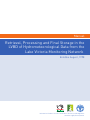
Manual
Retrieval, Processing and Final Storage in the
LVBD of Hydrometeorological Data from the
Lake Victoria Monitoring Network
Entebbe August, 1998
NILE BASIN INITIATIVE
Initiative du Bassin du Nil
Information Products for Nile Basin Water Resources Management
www.fao.org/nr/water/faonile
The designations employed and the presentation of material
throughout this book do not imply the expression of any opinion
whatsoever on the part of the Food and Agriculture Organization
(FAO) concerning the legal or development status of any country,
territory, city, or area or of its authorities, or concerning the
delimitations of its frontiers or boundaries.
The authors are responsible for the choice and the presentation
of the facts contained in this book and for the opinions expressed
therein, which are not necessarily those of FAO and do not commit
the Organization.
© FAO 2011
Table of Contents
Table of Contents
I
Introduction
7
1.1
General
7
1.2
Overview of the Contents of the Manual
7
1.3
Manual Version
8
2
Detailed Outline of the Data Trajectory
9
2.1
General
9
2.2
Hardware
9
2.3
Software
10
2.4
Comprehensive Data Trajectory
11
3
Remaining Hardware and Software Installation
13
3.1
Installation of SC532 Interface
13
3.2
Installation of PC208W Datalogger Support Software
13
4
Recommended Directory Structure
14
4.1
General
14
4.2
PC208W Files
14
4.3
MS Access Database Files
15
5
PC208W Datalogger Support Software
17
5.1
Introduction
17
5.2
StgModule Component
17
5.2.1
5.2.2
5.2.3
5.2.4
5.2.5
5.3
Report Component
5.3.1
5.3.2
Introduction
Connecting Storage Module to PC
Retrieving Raw Data Files
Pointers
Erasing Data Files
24
Introduction
Hydro Station
Manual
3
Table of Contents
5.3.2.1
5.3.2.2
5.3.2.3
5.3.2.1
Met Station
5.3.3
4
5.3.3.1
5.3.3.2
5.3.3.3
5.3.3.4
5.3.3.5
General
Hourly Hydrograph
Summarized Daily Water Level Information
Hydro Station Performance Information
General
Hyetograph
Summarized Hourly Meteorological Information
Summarized Daily Meteorological Information
Met Station Performance Information
6
Processing in MS Access and Final Storage in the LVBD
40
6.1
General
40
6.2
MS Access Database “LVBD_FinalProcessing”
41
6.3
Importing ASCII Files Generated by Report into MS Access
42
6.4
Transferring New Data Sets From Auxiliary to LVBD Format Table
49
6.5
Appending the Fully Processed New Data Sets to LVBD
52
Data Retrieval, Processing and Final Storage in the Lake Victoria Basin Database
List of Figures and Tables
List of Figures
Figure 1:
Figure 2:
Figure 3:
Figure 4:
Figure 5:
Hardware Components Involved in Data Acquisition Process
Software Components and File Formats Involved in
Data Acquisition Process
Recommended Directory Structure for PC208W and Related ‘Work’ Files
Recommended Directory Structure for MS Access Database Files
Final Data Processing Steps in MS Access
9
10
14
15
40
List of Tables
Table 1:
Table 2:
Table 3:
Table 4:
Table 5:
Table 6:
Comprehensive Data Trajectory
Various Files and their Function Used by Report in the
Processing of Hydro Data
Various Files and their Function Used by Report in the
Processing of Met Data
Database Objects and their Function in the MS Access
Database ”LVBD_FinalProcessing”
Designated Input and Output Tables for each Pre-Defined Append Query
LVBD Destination Objects
12
24
32
41
49
54
Manual
5
Annexes
Annexes
Annex 1:
Annex 2:
Annex 3:
Annex 4:
Annex 5:
Access.
Annex 6:
6
Consecutive Steps in Connecting Storage Module SM192 to PC.
Consecutive Steps in Retrieving Raw Data Files form SM192 Storage Module to PC.
Consecutive Steps in Processing Raw Data Files in Report.
Consecutive Steps in Final Processing of Report Output Files in MS Access and Appending Fully Processed New Data Sets to LVBD.
General Design of the Append Queries for Final Processing of the Report Output Files in MS
Design of the ID Converter Table.
Data Retrieval, Processing and Final Storage in the Lake Victoria Basin Database
Introduction
Introduction
1.1
General
The Lake Victoria Monitoring Network comprises of Automatic Hydro-meteorological Stations equipped with
electronic instruments for data acquisition and storage. Measurements are initially pre-processed and stored on site
in a digital storage and control module, commonly referred to as datalogger.
Periodically, the accumulated raw data are transferred from datalogger to a computer at the office of the hydrometeorological service. This is accomplished with the help of a portable data retrieval unit, which can serve several
stations during a single inspection tour. In order to enhance sustainability of the network, a visiting frequency of 1
month is proposed. Consequently, data should arrive at the office of the hydro-meteorological service with a delay
of maximum one month.
After transfer of the collected hydro-meteorological information from retrieval unit to PC, the newly imported data
should be processed, checked on consistency and possible measurement errors, and stored in a dedicated table in
the Lake Victoria Basin Database (LVBD), regarded as their final destination.
The first segment of the data trajectory, i.e. transfer of measurements form logger to retrieval unit, is covered in
two previously issued manuals:
•
•
Manual for Installation, Operation and Maintenance of Automatic Water Level Recording Stations;
Manual for Installation, Operation and Maintenance of Automatic Meteorological Stations.
The second part of the data track is dealt with in this manual. It covers in detail all steps involved in transferring the
accumulated hydro-climatological measurements from the retrieval unit to final storage in the LVBD in MS Access.
This includes:
•
•
•
•
•
•
installation and setup of involved hardware components;
transfer of raw data from retrieval unit to PC in a preliminary data and file format;
separation of individual parameters from preliminary data file to comma separated ASCII file, and first, visual
data quality check;
import of pre-processed ASCII file into MS Access;
rearrangement of newly imported data to final table structure using pre-defined queries, as well as a second,
computer operated quality check;
appending new data to LVDB.
This manual deals with data originating from both Automatic Weather Stations (AWS) and Automatic Water Level
Recording Stations (AWLRS). Since a substantial number of steps in the data trajectory apply identically to both
type of stations, no separate paragraphs for hydrometric and meteorologic information have been included for the
majority of processing actions. Only when the required operations for AWS and AWLRS are significantly different,
special station specific paragraphs have been prepared. The reader is requested to disregard the texts not applicable
for his or her situation.
1.2
Overview of the Contents of the Manual
This manual describes in detail all steps and operations involved in transferring the accumulated raw data from
retrieval unit to PC208W software on PC, processing the new information and subsequently storing it in the LVBD in
MS Access.
In order to provide the user with the complete picture of the information flow from sensor to database, chapter 2
presents a detailed outline of the comprehensive data trajectory, as well as all software and hardware components
involved, and their role.
Manual
7
Introduction
Chapter 3 focuses on the instructions for installing the hardware and software components that remained to be set
up.
A ‘recommended directory structure’ aimed at obtaining uniformity in the location of the concerned files on hard
drive is discussed in chapter 4.
Chapter 5 deals in detail with retrieving the raw data from the storage module to PC, and the initial processing of
this new information to a comma separated ASCII format, separated per parameter.
Finally, chapter 6 presents the instructions for importing the pre-processed new data set into MS Access,
performing a final processing round, and storing the data values into their final destination in the LVBD.
1.3
Manual Version
The current manual represents version 1.1. Since the project aims at preparing a set of automated modules for
performing a number of the steps discussed in this manual, it is expected that updated, amended and extended
editions will be issued in the future.
8
Data Retrieval, Processing and Final Storage in the Lake Victoria Basin Database
Detailed Outline of Data Trajectory
Detailed Outline of Data Trajectory
2.1
General
2.2
Hardware
This chapter gives an overview of the complete track a measurement value has to go from sensor to final storage
in the Lake Victoria Basin Database (LVBD). It presents the various hardware and software components involved in
this process, together with their interconnection. Furthermore, it lists sequentially all user actions that play a role
in the data trajectory.
Figure 1 presents all hardware components involved in the route from sensor to PC in the hydro-meteorological data
acquisition process
Figure 1: Hardware components involved in data acquisition process.
The various hydro-climatological parameters are measured using electronic sensors. Depending on the nature of a
parameter, its value is represented by either a voltage or a sum of pulses.
The datalogger measures the voltages and/or counts the pulses, and transfers them to intelligible figures in
standard units, like for example degrees Celsius for temperature or mm of rainfall for precipitation. Other tasks
of the datalogger are to activate the various sensors at pre-defined intervals, and store the measurements in its
memory.
The CR10KD keyboard display is used to communicate with the datalogger on site. For instance, in case the user
wants to invoke manual data transfer this is accomplished by connecting the CR10KD to storage module and logger,
and typing in the proper commands.
The SM192 storage module is used to transfer the accumulated raw data from datalogger on site to Personal
Manual
9
Detailed Outline of Data Trajectory
Computer at the office. It uses of a specific storage format which can not be read by normal PCs.
The role of the SC532 Interface is to convert this specific storage module format into a RS232 compatible one. The
latter is part of the communication standard for IBM compatible PCs.
Data processing, rearrangement and final storage in the LVBD is accomplished on PC.
2.3
Software
Figure 2 presents the various software packages and programs, as well as the concerned file formats, playing a
role in the data acquisition, processing and storage process..
Figure 2: Software components and file formats involved in data acquisition process.
The datalogger works under a specific Campbell Scientific operating system and is controlled by either the METSTAT
or HYDROSTN datalogger program, for meteorological and hydrometrical stations respectively. These programs are
specifically created by GCP/RAF/304/JPN for the sensor configuration and data requirements in the Lake Victoria
Monitoring Network. Once they work satisfactorily (as they have proved to do after extensive testing at the Project
Office), the two programs require no further user intervention.
As indicated in paragraph 2.2, data is transferred from datalogger to PC with help of the SM192 storage module.
This module uses a specific Campbell Scientific data format, which is extremely condensed in order to make optimal
use of its memory.
The next steps are performed in PC208W Datalogger Support Software. This concerns a package developed by
10
Data Retrieval, Processing and Final Storage in the Lake Victoria Basin Database
Detailed Outline of Data Trajectory
Campbell Scientific for communication between datalogger and PC. It consists of 8 modules of which only two are
directly needed in the data trajectory.
The StgModule component retrieves files from the SM192 Storage Module. All data is kept in the same structure
and sequence as in the datalogger. The entire contents of each single SM192 file is stored in a corresponding ASCII
file on PC.
The Report component, often referred to as Split, is used to restructure and separate these ASCII files according
to the required file/table structure of the user, transfer the Julian dates to months and days, and store the result in
a comma separated ASCII file. The latter format is preferred to import external data into MS Access.
Final data processing is accomplished in MS Access in a number of pre-defined tables and queries. Lastly, the
measurements are appended to the appropriate tables in the MS Access based Lake Victoria Basin Database.
2.4
Comprehensive Data Trajectory
In order to arrive at a complete understanding of the interconnections between the various hardware and software
elements that play a role in the data flow, table 1 presents a comprehensive overview of the entire data route, from
initial measurement to final dissemination. It shows the place and function of the respective hardware and software
items, and their interrelation. It furthermore lists in a sequential order all necessary user actions.
Not all steps described in table 1 are covered in this manual. They have been presented for the sake of completeness
and to come to full insight in the whole data trajectory. Issues treated elsewhere include step 1 and 2, which are
covered by the operation manuals for both AWS and AWLRS, and step 8 and 9, which will be dealt with in a future
version of this manual or in a separate document.
Consequently, as already indicated in paragraph 1.1, the current version (1.1) of this manual covers in detail step
3 to 7.
Manual
11
Detailed Outline of Data Trajectory
Table 1: Comprehensive Data Trajectory
Step
1
2
12
Operation
~ Periodic automatic measurement of
hydro-meteorologic paremeters
~ pre-processing and storage in the
datalogger’s RAM
Transfer of accumulated measurements
from logger’s RAM to portable SM192
Storage Module; each single transfer
exercise results in a separate data file
3
Transfer of data files from SM192
Storage Module to PC
4
Hardware Involved
Sensors + Datalogger
Datalogger + SM192
Storage Module +
CR10KD Keyboard
Display
Software Involved
~ Campbell Scientific Datalogger
Operating System (OS)
~ METSTAT or HYDROSTN
datalogger program
~ Campbell Scientific Datalogger
Operating System (OS)
~ METSTAT or HYDROSTN
datalogger program
SM192 Storage
Module + SC532
Interface + PC
StgModule component of
PC208W datalogger support
software
Separating and/or rearranging individual
hydro-meteorological parameters from a
complete, original data file
PC
Report (Split) component of
PC208W datalogger support
software
5
Exporting separated/rearranged hydrometeorological parameters to comma
separated ASCII file
PC
Report (Split) component of
PC208W datalogger support
software
6
~ Importing comma separated ASCII
file into MS Access and restructuring
data to LVBD format
~ Initial (automatic) quality control
PC
MS Access
(predefined tables and query)
7
Final Storage in the LVBD
PC
MS Access
(predefined tables, LVBD)
8
Further quality control of newlyadded
data
PC
MS Access
(LVBD)
9
Back-up and data dissemination
PC + modem +
telephone
Windows Explorer
CD -Write software
E-mail software
Data Retrieval, Processing and Final Storage in the Lake Victoria Basin Database
User Action
None
- Connect SM192 to datalogger
- Type in proper keyboard
commands
The user can choose between
automatic or manually invoked data
transfer
- Connect SM192 to SC532
- Activate StgModule Software
- Establish connection between PC
and SM192
- Invoke data transfer
- Activate Report software
- Open a ppropriate pre-defined
parameter file
- Select input data file
- Run Split
- First, visual data quality check
- Activate Report software
- Open appropriate pre-defined
paremeter file
- Select input data file
- Select and define output data file
- Run Split
- Activate MS Access
- Open appropriate database file
- Import ASCII file in predefined
table
- Activate predefined query to
restructure data format
- Copy contents of above mentioned
query results to the clip board
- Open appropriate LVBD file
- Open appropriate table
- Add data using paste -append
- Open appropriate LVBD file
- Open appropriate table
- Run pre-defined data-qualitycontrol queries
The various user actions involved in
this step will be discussed and
elaborated in a separate document.
Hardware and Software Installation
Hardware and Software Installation
3.1
Installation of SC532 Interface
Provided a PC has already been set up successfully, only one hardware item remains to be installed: the SC532
Interface. The function of this device is to connect IBM compatible computers to certain Campbell Scientific
peripherals, in this case the SM192 storage module, and convert their contents into RS232 format.
The SC532 has a 9-pin connector for linkage with the storage module and uses a 25-pin slot to connect to PC. It is
powered by an AC adapter.
Installation of the SC532 Interface is a straight forward process. Connect the SC532 to PC using the supplied ‘25 to
9’ computer cable. The 9-pin end should be connected to the PC’s serial port 1 or 2, while the 25-pin is to be plugged
into the SC532.
Connect the 9-pin connector on the SC532 to the SM192 Storage Module using the blue, specific Campbell
Scientific SC12 storage module cable. Since the SC532 Interface runs on 110V, use a 220 - 110 transformer between
mains and the SC532 while in East Africa.
All hardware components are now installed. Make sure power is supplied to the SC532.
3.2
Installation of PC208W Datalogger Support Software
PC208W Datalogger Support Software requires Windows 95 or higher. There needs to be at least 10Mb of free hard
disk space for software installation.
Insert the PC208W floppy disk labeled 1/4 in drive A. In Windows 95, select RUN from the Start button. Type in A:\
SETUP and click the OK button. Follow the instructions given on the screen.
It is recommended to use the following Working Directory name: C:/CAMPBELL/PC208W.
13
Data Retrieval, Processing and Final Storage in the Lake Victoria Basin Database
Recommended Directory Structure
Recommended Directory Structure
4.1
General
4.2
PC208W Files
For standardization and instruction purposes, this chapter proposes a Recommended Directory Structure. The user
is free to modify this if another system would better suit his or her particular computer organization. However,
the instructions presented in this manual are based on the proposed structure. Modification of it will require
corresponding adjustment of commands concerning file locations.
Figure 3 presents the Recommended Directory Structure for all files related to PC208W Datalogger Support
Software. A subdivision has been made between the PC208W program files and the ones actually used in the data
processing, the ‘work’ files.
Figure 3: Recommended Directory Structure for PC208W and related ‘work’ files..
The above proposition calls for the creation of a main folder called CAMPBELL on the C drive. This will consist of two
sub-folders named FILES and PC208W. The datalogger support software PC208W should be installed in the latter
one, see paragraph 3.2.
The FILES folder will be sub-divided into three parts: INPUT, OUTPUT and PARAMETER.
The INPUT sub-folder is destined for all data files retrieved from the SM192 storage module. By default these files
are give a DAT extension.
The OUTPUT sub-folder is allocated for all processed, comma separated ASCII files, with TXT extension. They
result from the separation and file restructuring exercise in Report (a.k.a. Split).
The PARAMETR sub-folder will be used to store all predefined Split files, having a PAR extension.
Use of the above mentioned files is discussed in chapter 5. The proposed structure is again illustrated in the
following Windows Explorer screen.
Manual
14
Recommended Directory Structure
For the creation of the various folders, use the appropriate Windows Explorer commands.
4.3
MS Access Database Files
Figure 4 presents the Recommended Directory Structure for storage of all data files in MS Access format .
Figure 4: Recommended Directory Structure for all data MS Access database files.
It has proofed beneficial to comply to the MS DOS file naming convention when dealing with database files. It is for
this reason that directory names are limited to 8 characters.
It is proposed to create a main database folder called MYDBASE on the C drive. This will consists of two sub-folders
called LVBD and PRE_LVBD. The former will be used to store the Lake Victoria Basin Database files, while the latter
is destined to contain the files imported from PC208W for final processing in MS Access, prior to being appended to
the appropriate LVBD data tables.
For the creation of the proposed directory structure, use the appropriate Windows Explorer commands. Once
more, the structure is illustrated in the below screen.
15
Data Retrieval, Processing and Final Storage in the Lake Victoria Basin Database
Recommended Directory Structure
Manual
16
PC208W Datalogger Support Software
PC208W Datalogger Support Software
5.1
Introduction
PC208W Datalogger Support Software is a Windows based software package specifically developed by Campbell
Scientific for communication between datalogger and PC. It consists of a help module and 7 independent datalogger
support components. Among them software for setting up a network of PC connected stations, and on-line datalogger
communication; modules which will not be used in this particular Lake Victoria application.
Smooth flow of data from datalogger to Lake Victoria Basin Database is accomplished with the help of the following
two PC208W units: StgModule and Report. The first serves to transfer raw data files from storage module to PC,
while the second is used to separate the various hydrometeorological parameters and re-arrange the data structure.
Both modules will be discussed in the below presented paragraphs.
The coming text does, however, not cover all aspects of the two employed PC208W components. Only the subjects
which are considered useful in the data down-loading process are discussed. The user is referred to the respective
Campbell Scientific Instruction Manuals, as well as the on-line help, in case of need of more information.
5.2
StgModule Component
5.2.1 Introduction
On-line information flow from datalogger to PC is not yet feasible in the East African environment due to the
unavailability of telephone connections at station site. Instead, the project has opted for the portable SM192 Storage
Module to transfer the accumulated raw data from the logger’s RAM to personal computer. This storage device can
contain up to almost 100,000 data values as well as a maximum of 8 datalogger programs. Communication between
storage module and PC is enabled through the StgModule software, discussed in this paragraph.
5.2.2 Connecting Storage Module to PC
lThis paragraph presents the instructions for establishing communication between SM192 and PC.
Step A1: Connect the SM192 Storage Module to the SC532 Interface using the blue SC12 cable.
Step A2: Make sure the SC532 Interface is powered.
Step A3: Double click the PC208W Datalogger Support Software Icon, presented below.
The following toolbar appears:
Step A4: Click the StgModule tab. A window alike the one presented below shows up.
The menu-bar contains four different items: File, Options, Data and Help. Just beneath this line 3 different tabs
17
Data Retrieval, Processing and Final Storage in the Lake Victoria Basin Database
PC208W Datalogger Support Software
are found, named CSM1/MCR1, SM192/SM716 and PCCard, each dealing with a different storage medium. Since the
Lake Victoria Monitoring Network is equipped with the SM192 unit, click the SM192/SM716 tab at the top-mid of the
screen to activate its specific communication software. Disregard the other two tabs.
Step A5: Click the SM192/SM716 tab at the top-mid of the SMS window.
The resulting window is divided into two halves: a status box on the right and a task specific sub- screen on the
left.
At the bottom-left of the latter, four different tabs are found: Setup, Programs, Data and Erase.
Step A6: Click the tab labeled ‘Setup’ to select the appropriate communication settings. The below screen
appears.
Manual
18
PC208W Datalogger Support Software
Step A7: Select the COM Port settings corresponding to the serial port used by the “9 to 25” computer cable
connecting the SC532 Interface (see paragraph 3.1). In most cases this will be either COM1 or COM2.
Step A8: Set Baud Rate at 19200. This is a measure of the communication speed between PC and Storage Module. In
case frequent communication problems are experienced, lower the Baud Rate and see if this solves the problem.
Step A9: Click the “Connect” button to connect SM192 to PC.
If communication is successfully established, a window similar to the one below appears. Note that the status box
is no longer empty and is now containing information on the module’s memory.
19
Data Retrieval, Processing and Final Storage in the Lake Victoria Basin Database
PC208W Datalogger Support Software
PC and Storage Module are now connected. The user can proceed with retrieving data files or other SM192 related
operations.
For ease of reference, the above presented steps are listed in Annex 1.
5.2.3 Retrieving Raw Data Files
This paragraph presents the user instructions for retrieving raw data files from the SM192 Storage Module and
storing them at a desired location on the PC’s hard drive.
Step B1: Connect SM192 to PC and establish communication. See instructions in paragraph 5.2.2.
Step B2: Click the “Data” tab at the bottom-left. The below window appears.
Note that switching between the various task-specific sub screens (Setup, Programs, Data and Erase) has no
influence on the contents of the Status Box.
Step B3: Mark the “Comma separated” option in the File Format select box. Import of comma separated ASCII files
into MS Access has proven to be flawless and trouble free.
Manual
20
PC208W Datalogger Support Software
Step B4: Mark the “Auto Increment Name” option in the Auto Name Control select box. Each retrieved data file
will get a name according to the format “DATAXXX.DAT” in which XXX is a number which automatically increments
when a new file is down loaded.
Step B5: Click the file name in the File Naming Options location (in the current example this is DATA024.DAT). A
box similar to Windows Explorer appears which allows the user to navigate to the location where he or she wants to
store the retrieved data files. See the window below.
21
Data Retrieval, Processing and Final Storage in the Lake Victoria Basin Database
PC208W Datalogger Support Software
If the user has opted for the Recommended Directory Structure (see paragraph 4.2), data files captured from the
SM192 should be stored in the following folder:
C:\CAMPBELL\FILES\INPUT
Step B6: Click the “Get New” button. This option collects all “new” data files from the SM192, i.e. all files not yet
retrieved in a previous down load operation. Each single SM192 data file is stored in an individual DAT file on the
hard drive.
For ease of reference, the above presented steps are listed in Annex 2.
5.2.4 Pointers
The Module Pointers area of the Status Box lists four different parameters, i.e. Free Space, Storage Ref. Pointer,
Display Pointer and Dump Pointer. Each of which is briefly discussed below:
Free Space:
As implicated by its name, Free Space concerns the number of free data locations in the SM192.
Storage Ref. Pointer: The Storage Reference Pointer (SRP) points to the SM192 location where the next data value will be written.
Display Pointer:
The Display Pointer points to the location which holds the first value which
will be output in response to the ‘Get One’ or ‘Get New’ data button in the Data
Control Section of the software.
The pointer can be set to any desired location by using the Display Pointer position box in the Advanced section of the data control status box, either by typing in the required loca
tion or clicking on the green arrow to move the pointer to successive filemarks. Manual
22
PC208W Datalogger Support Software
Dump Pointer:
This option is used to re-down load data from the SM192 which has already been retrieved in a previous operation. This can be useful in case of data loss.
The Dump Pointer is an internal pointer used for keeping track of the current ‘start-of-
dump’ for module to module data dumps. It indicates the first location from where new data should be collected. It is a function of the software to move this pointer after each successful data collection.
Especially the Display Pointer is useful if data is lost or corrupted during processing on PC. By manually setting
back the Display Pointer (see above and the on-line help for the appropriate instructions), data files can be
re-retrieved and re-processed, provided they still exist on the SM192 Storage Module.
5.2.5 Erasing Data Files
The user can decide to erase the information stored on the SM192. This applies both to data files and datalogger
programs. However, since the storage module is put by default in ring mode, there is no need to erase data at any
time. The moment the module is full, it starts overwriting the eldest information in the unit with new one, in this way
never restricting ‘new’ information to be recorded.
If the user would decide that periodic cleaning of the storage module serves his or her purposes, for example to
avoid confusion between two different field visits, the below text presents instructions how to do this.
To activate the Erase Control screen, click the “Erase” tab at the bottom-left of the SMS Window. The below
presented screen will appear.
23
Data Retrieval, Processing and Final Storage in the Lake Victoria Basin Database
PC208W Datalogger Support Software
The Erase Control box contains three different options, each having self-explanatory names. Since it is advised to
leave an uncorrupted version of the applicable datalogger program at all times in program location 8 of the storage
module, the recommended option is number 1: Erase Data. No further user interactions are required.
5.3
Report Component
5.3.1 Introduction
The Report module, often referred to as Split, is used to separate individual hydro-meteorological parameters
from the raw data file and put them into a format used in the various ‘target’ databases. It essentially performs the
following operation: it reads an input file, splits and re-arranges it using a predefined parameter file, and stores the
result in an output file.
Since the raw data files for hydro and meteorological stations are significantly different, user instructions for the
two stations are discussed in separate paragraphs.
5.3.2 Hydro Station
5.3.2.1General
As its essential activity, the Hydro Station is programmed to measure water level at a 15 minutes interval. In addition
to this, it monitors two station performance indicators on a daily basis: program signature and battery voltage. The
HYDROSTN datalogger program transfer these measurements into three different information products, i.e.:
•
•
•
hydrograph with a time step of 1 hour;
summary information on a daily basis including average, maximum and minimum water level, as well as
standard deviation of the 15 minutes measurements with respect to the daily average; the latter as a measure
of the daily fluctuation;
station performance information on a daily basis: as an indicator of the functioning of datalogger and power
unit.
Due to the logger’s memory configuration, all three information items are written to the same storage area in the
datalogger’s RAM in the order of their time of recording, and consequently retrieved as a single, rather unorganized
data file, through the SM192, on PC. The function of the Report module is now to separate and re-arrange the
scattered recordings into consistent individual data blocks per information product, that can be appended to the
existing databases without too much further processing.
Report performs this operation using so called parameter files. Each information product is generated from the
single raw data file with a specific pre-defined parameter file, and stored into an individual output file on the hard
drive. At the same time the output data is presented on screen for a first visual quality check.
Table 2: Various files and their function used by Report in the processing of Hydro Station recordings.
Function
Input File
Parameter File
to extract hourly hydrograph information from data file
data0XX.dat
hydrohr.par
to extract daily summary water level information from data file
data0XX.dat
hydroday.par
to extract station performance information from data file
data0XX.dat
hydroprf.par
Output File
hydhrXX.txt
hyddayXX.txt
not applicable
Each of these three data products is dealt with more in detail in the next three sub paragraphs.
5.3.2.2 Hourly Hydrograph
The following text describes the procedures for composing a hydrograph with a time step of one hour from a raw
data file, and storing the result in an output file in proper format for final processing.
Step C1 Activate Report by clicking the Report tab on the PC208W toolbar. The below screen appears.
Manual
24
PC208W Datalogger Support Software
Step C2: Choose Open from the File menu to activate a pre-defined parameter file, as indicated in the following
window.
25
Data Retrieval, Processing and Final Storage in the Lake Victoria Basin Database
PC208W Datalogger Support Software
Step C3: Navigate to the location on hard drive which contains the parameter files. This is “C:\CAMPBELL\FILES\
PARAMETR” if the Recommended Directory Structure is used. Highlight the file “hydrohr.par”, as shown on the
window below. Click OK.
The title bar on the Split window now indicates the name of the open parameter file.
Step C4: Activate the Input File(s) sub-window and select the Input Data File. To this end click “Browse” in the Input
Data File box and navigate to the location on hard disk which contains the data files. This is pictured in the following
screen. Highlight the appropriate file and click OK.
Manual
26
PC208W Datalogger Support Software
Step C5: Switch to the Output File sub-window by clicking its tab at the top-mid of the current Split screen. The
below window pops up.
27
Data Retrieval, Processing and Final Storage in the Lake Victoria Basin Database
PC208W Datalogger Support Software
Step C6: Select location for, and give a name to, the resulting Output file. To this end click “Browse” in the Output
Data box. Navigate to the desired folder on the hard drive and type in an output file name according to the following
convention:
hydhrXX.txt
in which XX is the serial number of the input data file. For instance “hydhr15.txt” when originating from “data015.
dat”. Click OK. This process is presented in the below window.
Step C7: Finalize the routine by selecting Go from the Run menu. The results, as presented on screen, are shown
below.
Manual
28
PC208W Datalogger Support Software
For every hour, the following information is generated: Station-ID, Year, Date, Time and Average 1-Hour Water
Level in cm. The first four items of this list uniquely identify each output array.
The associated output file is in comma separated ASCII format. This is shown below for the output file corresponding
to the above screen: file “hydhr15.txt”.
29
Data Retrieval, Processing and Final Storage in the Lake Victoria Basin Database
PC208W Datalogger Support Software
This concludes the user activities in Report with respect to the hourly hydrograph information.
For ease of reference, the above presented steps are listed in Annex 3.
5.3.2.3 Summarized Daily Water Level Information
Compilation of summarized daily water level information is a similar process as the one described in the previous
paragraph. The reader is referred to this text, and Annex 3, for detailed instructions on steps 1 to 5. In this case the
parameter file “hydroday.par” should be used.
Steps 6 and 7 are discussed more in detail in the remaining part of this paragraph, although also these steps are
essentially analog to the ones discussed in paragraph 5.3.2.2.
Step C1-5: Perform the same actions as presented in the previous paragraph. Use parameter file “hydroday.
par”.
Step C6: Select location for, and give a name to, the resulting Output file. To this end click “Browse” in the Output
Data box. Navigate to the desired folder on the hard drive and type in an output file name according to the following
convention:
hyddayXX.txt
in which XX is the serial number of the input data file. For instance “hydday15.txt” when originating from “data015.
dat”. Click OK. This process is presented in the below window.
Step C7: Finalize the routine by selecting Go from the Run menu. The results, as presented on screen, are analogue
to the window below.
Manual
30
PC208W Datalogger Support Software
For every day the Hydro Station has been operational, the following information is generated: Station-ID, Year,
Date, Average Daily Water Level, Maximum and Minimum Daily Water Level, and lastly the Daily Standard Deviation
of the 15 minutes Water Level Recordings.
The three first parameters make sure that each array is uniquely identified.
The associated output file is in comma separated ASCII format. This is shown below for the output file corresponding
to the above screen: “hydday15.txt”.
31
Data Retrieval, Processing and Final Storage in the Lake Victoria Basin Database
PC208W Datalogger Support Software
This concludes the user activities in Report with respect to the Summarized Daily Water Level information.
5.3.2.4 Hydro Station Performance Information
It is up to the user to decide whether or not to archive datalogger performance information of the various Hydro
Stations. Although this information can be used to, for example, analyze station power consumption in the past, there
seems to be little reason to keep this data if the station has proved to work satisfactorily during a previous recording
period.
It is for this reason that the Project has decided not to make any provisions (i.e. pre-defined tables and/or queries)
for storing station specific datalogger performance information in an MS Access database.
If the user considers it beneficial for the operation of his/her office to archive the concerned performance
indicators, he or she is invited to create an appropriate database for this purpose.
5.3.3 Met Station
5.3.3.1 General
The Automatic Meteorological Stations are equipped with 6 sensors for monitoring a selected set of climatological
parameters at a five minutes interval. At the same time the system periodically records two performance indicators:
battery voltage and program signature.
The METSTAT datalogger program transfers these measurements into four different information groups, i.e.:
• hyetograph with a 5 minutes time step;
• summary meteorological information on an hourly basis, including average hourly values for air temperature,
relative humidity, wind speed and direction, as well as cumulative one-hour solar radiation;
• summary meteorological information on a daily basis, including average, maximum and minimum air
temperature; average daily values for relative humidity, wind speed and direction; as well as cumulative oneday rainfall and solar radiation;
• station performance information on a daily basis as an indicator of the functioning of datalogger and power
supply.
Due to the logger’s memory configuration, all four information products are written to the same storage area in the
system’s RAM in the order of their time of recording, and consequently retrieved as one single, rather unorganized
data file, through SM192, on PC. The role of the Report module is now to separate and reorganize the scattered
recordings into consistent individual data blocks per information product.
Report performs this task using so called parameter files. Each of the four information products is extracted from
the single data file using a pre-defined dedicated parameter file and stored into an individual output file on the hard
drive. At the same time the output data is presented on screen for a first visual quality check.
Table 3 presents the various files involved. XX stands for the data file’s serial number.
Table 3: Various files and their function used by Report in the processing of Met Station recordings.
Function
Input File
Parameter File
to extract (5 minutes) hyetograph information from data file to
data0XX.dat
metrain.par
extract 1 hour summary information from data file
data0XX.dat
methour.par
to extract 1 day summary information from data file
data0XX.dat
metday.par
to extract station performance information from data file
data0XX.dat
metperf.par
Output File
m e t r n X X .
txtmethrXX.
txtmetdayXX.
txtmetprfXX.txt
Each of the four above identified information products is dealt with more in detail in the next four sub
paragraphs.
Manual
32
PC208W Datalogger Support Software
5.3.3.2 Hyetograph
Only in case of a rainfall event, a cumulative 5 minutes rainfall value is written to the logger’s RAM at the end of the
interval. In contrast, when the rain gage is not measuring precipitation, the data values (thus zeros) are not recorded.
Consequently, the hyetograph information product consists of a single time series of total 5 minutes precipitation in
which each storm immediately follows a previous one. Gaps in the recorded time series indicate dry periods.
Compilation of hyetograph information is a similar process as the one described in paragraph 5.3.2.2. The reader
is referred to this text, and Annex 3, for detailed instructions on steps 1 to 5. In this case the parameter file “metrain.
par” should be used.
Steps 6 and 7 are discussed more in detail in the remaining part of this paragraph, although also these steps are
essentially analog to the ones discussed in paragraph 5.3.2.2.
Step C1-5: Perform the same actions as presented in the previous paragraph. Use parameter file “metrain.par”.
Step C6:In the File name text box of the Select Output File sub-screen, type in the name of the output file. Apply
the following naming format:
metrnXX.txt
in which XX is the serial number of the input data file. For instance “metrn16.txt” if originating from “data016.dat”.
Click OK. This process is presented in the below window.
Step C7: Finalize the routine by selecting Go from the Run menu. The results, as presented on screen, are similar
to the window below.
33
Data Retrieval, Processing and Final Storage in the Lake Victoria Basin Database
PC208W Datalogger Support Software
For every five minutes interval for which rainfall is recorded, the following information is generated: station-ID,
year, date and time, and cumulative five minutes rainfall.
The first four parameters guarantee that each array is uniquely identified.
The associated output file is in comma separated ASCII format. This is shown below for the output file corresponding
to the above screen: “metrn16.txt”.
Manual
34
PC208W Datalogger Support Software
This concludes the user activities in Report with respect to the Hyetograph information product.on in which each
storm immediately follows a previous one. Gaps in the recorded time series indicate dry periods.
5.3.3.3 Summarized Hourly Meteorological Information
Compilation of hourly meteorological information is a similar process as the one described in paragraph 5.3.2.2. The
reader is referred to this text, and Annex 3, for detailed instructions on steps 1 to 5. In this case the parameter file
“methour.par” should be used.
Steps 6 and 7 are discussed more in detail in the remaining part of this paragraph, although also these steps are
essentially analog to the ones discussed in paragraph 5.3.2.2.
Step C1-5: Perform the same actions as presented in the previous paragraph. Use parameter file “methour.par”.
Step C6: In the File name text box of the Select Output File sub-screen, type in the name of the output file. Apply
the following naming format:
methrXX.txt, in which XX is the serial number of the input data file. For instance “methr16.txt” if originating from
“data016.dat”. Click OK. This process is presented in the below window.
Step C7: Complete the routine by selecting Go from the Run menu. The results, as presented on screen, are similar
to the window below.
35
Data Retrieval, Processing and Final Storage in the Lake Victoria Basin Database
PC208W Datalogger Support Software
For every full hour the Met Station has been operational, the following information is generated: station-ID, year,
date and time; average one-hour air temperature, vapor pressure, vapor pressure deficit and wind speed; total onehour solar radiation.
The associated output file is in comma separated ASCII format. This is shown below for the output file corresponding to the above screen: “methr16.txt”.
Manual
36
PC208W Datalogger Support Software
This concludes the user activities in Report with respect to the hourly meteorological information.
5.3.3.4 Summarized Daily Meteorological Information
Compilation of daily meteorological information is a similar process as the one described in paragraph 5.3.2.2. The
reader is referred to this text, and Annex 3, for detailed instructions on steps 1 to 5. In this case the parameter file
“metday.par” should be used.
Steps 6 and 7 are discussed more in detail in the remaining part of this paragraph, although also these steps are
essentially analog to the ones discussed in paragraph 5.3.2.2.
Step C1-5: Perform the same actions as presented in the previous paragraph. Use parameter file “metday.par”.
Step C6: in the File name text box of the Select Output File sub-screen, type in the name of the output file. Apply
the following naming format:
metdayXX.txt in which XX is the serial number of the input data file. For instance “metday16.txt” if originating from
“data016.dat”. Click OK. This process is presented in the below window.
37
Data Retrieval, Processing and Final Storage in the Lake Victoria Basin Database
PC208W Datalogger Support Software
Step C7: Complete the routine by selecting Go from the Run menu. The results, as presented on screen, are similar
to the window below.
Manual
38
PC208W Datalogger Support Software
For every day the Met Station has been operational, the following information is generated: station-ID, year and
date; average, maximum and minimum daily air temperature; average vapor pressure and vapor pressure deficit;
total daily rainfall and solar radiation; average daily wind speed and direction, as well as standard deviation of the
wind direction.
The first three parameters uniquely identify each output array.
The associated output file is in comma separated ASCII format. This is shown below for the output file corresponding to the above screen: “metday16.txt”.
This concludes the user activities in Report with respect to the daily meteorological information.
5.3.3.5 Met Station Performance Information
Similar as for the Hydro Station, it is considered up to the user to decide whether or not to archive datalogger
performance information of the various Met Stations. Although this information can be used to, for example, analyze
station power consumption in the past, there seems to be little reason to keep this data if the station has proved to
work satisfactorily during a previous recording period.
It is for this reason that the Project has decided not to make any provisions (i.e. pre-defined tables and/or queries)
for storing station specific datalogger performance information in an MS Access database.
If the user considers it beneficial for the operation of his/her office to archive the concerned performance
indicators, he or she is invited to create an appropriate database for this purpose.
39
Data Retrieval, Processing and Final Storage in the Lake Victoria Basin Database
Processing in MS Access and Final Storage into the LVBD
Processing in MS Access and Final Storage into
the LVBD
6.1
General
Final destination of the hydro-meteorological data obtained from the Lake Victoria Monitoring Network is the
LVBD: the Lake Victoria Basin Database developed in MS Access. But prior to coming to the final step of adding new
measurements to this database, one more intermediate operation has to be performed: importing the ASCII files
generated by Report (as described in the previous chapter) into MS Access and restructuring them into a final LVBD
format.
Figure 5 shows the remaining part of the data trajectory, i.e. the final processing actions in MS Access.
Figure 5: Final data processing steps in MS Access.
The following paragraphs will present the detailed instructions for performing the tasks indicated in the above
figure.
Manual
40
Processing in MS Access and Final Storage into the LVBD
6.2
MS Access Database “LVBD Final Processing”
The remaining data processing activities are carried out in a MS Access database called “LVBD_FinalProcessing.
mdb”. If the user is applying the recommended directory structure, this file is stored in the sub folder C:\MyDbase\
Pre_LVBD.
This database contains several pre-defined objects including 11 tables and 5 append queries. Table and query names are listed
in table 4 together with a brief description of their function.
As indicated by their numbering, the various database objects listed in table 4 are divided into four different classes.
•
•
•
•
Group 1 is formed by the auxiliary tables in which to import the respective comma separated ASCII files generated in Report.
Class 2 constitutes of a single ID-converter table used to relate the short datalogger IDs to a final official station
identifier.
Group 3 consists of the tables in final LVBD format in which the fully processed new information is kept up to being added
to the LVBD.
Lastly, class 4 is formed by the respective append queries used to generate the LVBD format table from the related
auxiliary one.
Table 4: Database objects and their function in MS Access database “LVBD_FinalProcessing.mdb”.
Typettable
No.
Object
Function
table
1.1
HydroDay
pre-defined table in which to import comma separated ASCII
file “hyddayXX.txt” generated by Report (see paragraph 5.3)
table
1.2
HydroHour
ditto for “hydhrXX.txt”
table
1.3
MetDay
ditto for “metdayXX.txt”
table
1.4
MetHour
ditto for “methrXX.txt”
table
1.5
MetRain
ditto for “metrnXX.txt”
table
2
ID Converter
table relating datalogger IDs to Hydromet station number or
other identifier
table
3.1
Additional Daily Hydro
pre-defined table in LVBD format for storage of fully procAWLRS
essed daily hydrometric data; from this table the data is appended to the appropriate corresponding table in the LVBD
table
3.2
Additional
ditto for hourly hydrometric data
Hydrographs AWLRS
table
3.3
Additional Daily Clim AWS
ditto for daily climatological data
table
3.4
Additional Hourly Clim
ditto for hourly climatological data
AWS
append query
3.5
Additional
Hyetographs
ditto for 5-minutes rainfall series
AWS
append query
4.1
Daily Hydro AWLRS
pre-defined append query to transfer the contents of table
“hydroDay” into final LVBD format in table “Additional Daily
Hydro AWLRS”
append query
4.2
Hydrograph AWLRS
ditto for hydroHour
append query
4.3
Daily Clim AWS
ditto for MetDay
append query
4.4
Hourly Clim AWS
ditto for MetHour
append
query
4.5
Hyetograph AWS
ditto for MetRain
41
Data Retrieval, Processing and Final Storage in the Lake Victoria Basin Database
Processing in MS Access and Final Storage into the LVBD
The individual database items in a particular object class are subject to similar final processing. For example, the
actions for importing ASCII file ‘metdayXX.txt” into Access are equivalent to those for “methrXX.txt”, “metrnXX.txt”,
etc., only table and file names differ. The same applies for running the various append queries and adding the fully
processed data to the LVBD.
It is because of this fact, and the wish to avoid redundancy, that this manual presents the detailed user instructions
for only one member of each object class. The instructions for the remaining members are analog.
6.3 Importing ASCII files generated by Report into MS Access
This paragraph presents the user instructions for importing “methrXX.txt” into Access file “LVBD_FinalProcessing.
mdb”. Similar commands are applied for importing “metdayXX.txt”, “metrnXX.txt”, hyddayXX.txt” and “hydhrXX.
txt”.
Step D1: Open the MS Access file “LVBD_FinalProcessing.mdb” in folder C:\MyDbase\Pre_LVBD. If in table view,
the following database window appears:
The view shows the 11 pre-defined tables.
Step D2: Highlight the table “MetHour” and click “Open”. This results in the next screen.
Manual
42
Processing in MS Access and Final Storage into the LVBD
In the above screen, the MetHour table still contains data from a previous transfer exercise. Although primary
key setting in the final LVBD tables do not allow for data duplication, it is good policy to delete all records from the
auxiliary tables, in this case MetHour, prior to a processing a new data set. To this end, continue with step 3.
Step D3: Select all records by simultaneously keying CTRL and A, or clicking Select All Records in the Edit menu.
The complete record set is now highlighted.
Step D4: Delete all records by choosing Delete Records from the Edit menu, as shown on the next screen, or by
pressing the ‘Delete’ key.
43
Data Retrieval, Processing and Final Storage in the Lake Victoria Basin Database
Processing in MS Access and Final Storage into the LVBD
Step D5: Close MetHour.
The auxiliary MetHour table is now empty. No data duplication will occur unless the user imports a certain data
set twice. Although this would eventually be refused by MS Access due to ‘key violation’, it is recommended not to
enter this situation. Continue with step 6.
Step D6: In the database window, select Get External Data from the File menu. Choose the sub command Import,
as presented below.
Manual
44
Processing in MS Access and Final Storage into the LVBD
Step D7: In the subsequent window, navigate to the folder containing the Report output files and select the
concerned “merhrXX.txt” file. Use the appropriate Windows Explorer operations. If the recommended directory
structure is used, “methrXX.txt” is stored in folder C:\CAMPBELL\FILES\OUTPUT. Make sure the ‘Files of type:’ box
below-left is in Text Files. The resulting screen is depicted below.
45
Data Retrieval, Processing and Final Storage in the Lake Victoria Basin Database
Processing in MS Access and Final Storage into the LVBD
Step D8: Click Import.
The following Text Import Wizard pops up.
The Report output files are comma-separated and thus fall into the category ‘delimited’. This has been done on
purpose since importing this format into MS Access has proved to be straight forward and flawless. Continue with
step 9.
Step D9: Select ‘Delimited” and click ‘Next’.
The below screen appears, it shows how the imported text will be divided into various columns according to the
applied delimiter.
Manual
46
Processing in MS Access and Final Storage into the LVBD
Step D10: Select ‘comma’ and click ‘Next’.
The subsequent window is used to define the output location for the imported data. In this particular case, the new
information is appended to the pre-defined auxiliary table MetHour.
Step D11: Check “In an Existing Table:” and navigate in the related list box to the MetHour table. Click ‘Next’.
This constitutes the final step in importing the ‘methrXX.txt’ ASCII file in the appropriate pre-defined MS Access
47
Data Retrieval, Processing and Final Storage in the Lake Victoria Basin Database
Processing in MS Access and Final Storage into the LVBD
table.
If no importing errors are encountered, the Text Import Wizard finishes the process by presenting the following
message.
Step D12: Click OK.
The text file is now imported in its desired location. View the results by opening the MetHour table in the database
window. The result is presented below.
This step concludes the transfer of the contents of the Report Output file ‘methrXX.txt’ into the appropriate location
for final processing in MS Access.
As already stated at the beginning of this paragraph, the import procedures for ‘metdayXX.txt’, ‘metrnXX.txt’,
‘hyddayXX.txt’ and ‘hydhrXX.txt’ are analog to the process presented above.
To ingress the above ASCII files into ‘LVBD_FinalProcessing.mdb’, the user is requested to change file and table
names where and when necessary.
Manual
48
Processing in MS Access and Final Storage into the LVBD
For ease of reference, all steps discussed in this paragraph are again presented, in proper sequence, in Annex 4.
This time however without accompanying comments and illustrations.
6.4
Transferring new data sets from Auxiliary to LVBD Format Table
After being imported into an auxiliary table in MS Access, the new data sets are subject to the following final
processing:
•
•
•
•
•
two separate text fields containing day and month, and year respectively, have to be converted into a single
date field;
short datalogger ID (due to the logger’s memory configuration limited to a number below 255) has to be
transferred into an official numerical station identifier, for example in case of Hydromet-IDs consisting of 8
digits;
automatic quality control: checking if the data values are within an expected range;
adding of ‘source’ value: indicating the origin of the data set;
re-arranging column structure to LVBD format.
For each data type, all these actions are automatically performed in one go with a pre-defined append query. When
the Queries tab is activated in the database view, 5 pre-created queries appear, as shown in the window below.
Table 5presents the input and output tables for each of the above queries. AWS stands for Automatic Weather
Station while AWLRS is the acronym for Automatic Water Level Recording Station.
For reference purposes, the general query design is presented in Annex 5. The function and design of the
ID-Converter table, included in the various queries, is discussed in Annex 6.
Table 5: Designated Input and Output table for each pre-defined append query.
Query
Input Table
Output Table
Hourly Clim AWS
MetHour
Additional Hourly Clim AWS
Daily Clim AWS
MetDay
Additional Daily Clim AWS
Hyetograph
AWS
MetRain
Additional Hyetograph AWS
Hydrograph AWLRS
HydroHour
Additional Hydrograph AWLRS
Daily Hydro AWLRS
HydroDay
Additional Daily Hydro AWLRS
49
Data Retrieval, Processing and Final Storage in the Lake Victoria Basin Database
Processing in MS Access and Final Storage into the LVBD
Continue the data processing exercise by performing step 13.
Step D13: Finalize data processing by activating the appropriate query. For example, highlight the ‘Hourly Clim
AWS’ append query to process the newly imported data set in the MetHour table. Click Open. The results will be
stored in table ‘Additional Hourly Clim AWS’.
The following message box pops up.
Step D14: Click Yes.
A message box similar to the one below follows.
Step D15: Click Yes.
This steps finalizes the data processing. The destination table is by its primary key settings protected against
duplicate records. If a certain record would be added for the second time, the following message box shows up.
It indicates that the processing operation is carried out but that any double rows will not be added due to ‘key
violations’. Click Yes to perform the query to process the genuinely new data.
Manual
50
Processing in MS Access and Final Storage into the LVBD
In order to visualize the final results, open the ‘Additional Hourly Clim AWS’ table in database view.
Step D16: Highlight ‘Additional Hourly Clim AWS’ table and click Open.
This is presented below.
The screen presents the fully processed data set in LVBD format. Note the combined Station-ID, Date, Time and
Source fields uniquely identifying each record.
51
Data Retrieval, Processing and Final Storage in the Lake Victoria Basin Database
Processing in MS Access and Final Storage into the LVBD
6.5 Appending the fully processed new data set to LVBD
Data processing has been finalized in the previous paragraph. What remains is adding the new records to the Lake
Victoria Basin Database. Because the new, fully processed data set is already in LVBD format, this operation is easily
accomplished by copying the new records to the clipboard, opening the destination file and table in the LVBD, and
adding the new information using the ‘paste-append’ option.
This process is described in the following steps. It builds on the output of step D16 in the preceding paragraph.
Continue with step 17 in the open ‘Additional Hourly Clim AWS’ table.
Step D17: Select all records by simultaneously keying CTRL and A, or clicking Select All Records in the Edit
menu.
The complete record set is now highlighted. Proceed with copying the entire data set to the clipboard, as follows.
Step D18: Choose Copy from the Edit menu.
This action is pictured in the below screen.
Manual
52
Processing in MS Access and Final Storage into the LVBD
In order to improve computing speed, storing data on the clipboard is normally limited to copying a reference
to an open source object to this location. However, if this ‘origin’ table has to be closed, the actual data has to be
transferred to the clipboard, which can be a rather lengthy process and may occupy a substantial amount of memory.
Since MS Access does not allow two databases to be open at the same time, opening a LVBD destination file and
table must be preceded with closing the auxiliary ‘LVBD_PreProcessing”. This is the source in the ongoing append
exercise, and its closure will provoke actual copying of all supplement records to the clipboard. Continue with step
19.
Step D19: Close the ‘Additional Hourly Clim AWS’ table.
Step D20: Close the ‘LVBD_FinalProcessing’ database.
On closing the ‘LVBD_FinalProcessing.mdb’ file, the below message box pops up.
53
Data Retrieval, Processing and Final Storage in the Lake Victoria Basin Database
Processing in MS Access and Final Storage into the LVBD
Step D21: Click Yes.
Depending on the type and origin of the copied data, a destination LVBD data table should be opened. Table 6
presents the various data sources and their related ‘target’ files and tables in the LVBD.
Table 6: LVBD destination objects.
Source Table in auxiliary database
‘LVBD_FinalProcessing’
Additional Daily Clim AWS
Additional Hourly Clim AWS
Additional Hyetograph AWS
Additional Daily Hydro AWLRS
Additional Hydrograph AWLRS
Destination LVBD file
Destination LVBD table
Depending on the country of origin of the AWS
data, this is one of the files listed hereunder:
- ‘Daily Clim Kenya.mdb’
- ‘Daily Clim Tanzania.mdb’
- ‘Daily Clim Uganda.mdb’
ditto
ditto
‘Daily Runoff.mbd’
ditto
AWS Daily Clim
AWS Hourly Clim
AWS Hyetograph
AWLRS Daily Water Levels
AWLRS Hydrographs
Step D22: Open the destination LVBD database file. In this example we have arbitrarily selected ‘Daily Clim Uganda.
mdb’. The following database window shows up, presenting the included tables.
Step D23: Open the destination LVBD data table. In the current example this is table ‘AWS Hourly Clim”.
Step D24: Append the contents of the clipboard into this table by selecting the Paste Append option from the Edit
menu. As shown in the screen below.
Manual
54
Processing in MS Access and Final Storage into the LVBD
he following message box pops up.
Step D25: Click Yes.
This step finalizes the append exercise and concludes the data route from sensor to LVBD. The final results are
shown in the window below.
The various LVBD tables are protected against duplicate records by their primary key setting. Appending double
records is therefore not permitted. However, a possible doubled record will automatically be disregarded and does
not corrupt or halt the append process.
55
Data Retrieval, Processing and Final Storage in the Lake Victoria Basin Database
Processing in MS Access and Final Storage into the LVBD
Obviously, the append exercise for the other source and destination objects in table 6 is equivalent to the process
discussed in this paragraph. In the listed steps, simply substitute the names of the source table, as well as the target
LVBD file and table, with the appropriate ones and follow the above provided guide lines.
Manual
56
Annexes
Annexes
Annex 1: Consecutive Steps in Connecting Storage Module SM4M/SM192 to PC.
Annex 1: Consecutive Steps in Connecting Storage Module SM192 to PC.
Step
A1
A2
A3
A4
A5
A6
A7
A8
A9
Action
Connect the SM192 Storage Module to the SC532 Interface using the blue SC12 cable.
Make sure the SC532 Interface is powered.
On PC, double click the PC208W Datalogger Support Software Icon.
Click the StgModule tab.
Click the SM192/SM716 tab at the top-mid of the SMS window.
Click the tab labeled ‘Setup’ to select the appropriate communication settings.
Select the COM Port settings corresponding to the serial port used by the “9 to 25” computer cable connecting
the SC532 Interface (see paragraph 3.1). In most cases this will be either COM1 or COM2.
Set Baud Rate at 19200. This is a measure of the communication speed between PC and Storage Module. In case
frequent communication problems are experienced, lower the Baud Rate and see if this solves the problem.
Click the “Connect” button to connect SM192 to PC.
The above steps are discussed in detail in paragraph 5.2.2 of this manual.
Annex 2: Consecutive Steps in Retrieving Raw Data Files from SM192 Storage Module
to PC
Annex 2: Consecutive Steps in Retrieving Raw Data Files from SM192 Storage Module to PC
Step
B1
B2
B3
B4
B5
B6
Action
Connect SM192 to PC and establish communication. See instructions in paragraph 5.2.2 or Annex 1.
Click the “Data” tab at the bottom-left.
Mark the “Comma separated” option in the File Format select box. Import of comma separated ASCII files into
MS Access has proven to be flawless and trouble free.
Mark the “Auto Increment Name” option in the Auto Name Control select box. Each retrieved data file will get a
name according to the format “DATAXXX.DAT” in which XXX is a number which automatically increments when a
new file is down loaded.
Click the file name in the File Naming Options location. A box similar to Windows Explorer appears which allows
the user to navigate to the location where he or she wants to store the retrieved data files.
Click the “Get New” button. This option collects all “new” data files from the SM192, i.e. all files not yet retrieved
in a previous down load operation. Each single SM192 data file is stored in an individual DAT file on the hard
drive.
The above steps are discussed in detail in paragraph 5.2.3 of this manual.
57
Data Retrieval, Processing and Final Storage in the Lake Victoria Basin Database
Annexes
Annex 3: Consecutive Steps in Processing Raw Data Files in Report.
Annex 3:Consecutive Steps in Processing Raw Data Files in Report.
Step
C1
C2
C3
C4
C5
C6
C7
Action
Activate Report by clicking the Report tab on the PC208W toolbar.
Choose Open from the File menu to activate a pre-defined parameter file.
Navigate to the location on hard drive which contains the parameter files. This is “C:\CAMPBELL\FILES\PARAMETR” if the Recommended Directory Structure is used. Highlight the concerned parameter file and click OK.
Activate the Input File(s) sub-window and select the Input Data File. To this end click “Browse” in the Input Data
File box and navigate to the location on hard disk which contains the data files. Highlight the appropriate file
and click OK.
Switch to the Output File sub-window by clicking its tab at the top-mid of the current Split screen.
Select location for, and give a name to, the resulting Output file. To this end click “Browse” in the Output Data
box. Navigate to the desired folder on the hard drive and type in an output file name according to the convention
discussed in paragraph 5.3.2.2. Click OK.
Finalize the routine by selecting Go from the Run menu.
The above steps are discussed in detail in the paragraphs 5.3.2 and 5.3.3 of this manual.
Manual
58
Annexes
Annex 4: Consecutive Steps in Final Processing of Report Output Files in MS Access
and Appending Fully Processed New Data Sets to LVBD.
Annex 4: Consecutive Steps in Final Processing of Report Output Files in MS Access and Appending Fully Processed New Data Sets to LVBD.
Step
D1
D2
D3
D4
D5
D6
D7
D8
D9
D10
D11
D12
D13
D14
D15
D16
D17
D18
D19
D20
D21
D22
D23
D24
D25
Action
Open the MS Access file “LVBD_FinalProcessing.mdb” in folder C:\MyDbase\Pre_LVBD.
Highlight the appropriate auxiliary table and click “Open”. See Table 4 in paragraph 6.2 for an overview of the
auxiliary tables (Class 1).
Select all records by simultaneously keying CTRL and A, or clicking Select All Records in the Edit menu.
Delete all records by choosing Delete Records from the Edit menu, or by pressing the ‘Delete’ key.
Close auxiliary table.
In the database window, select Get External Data from the File menu. Choose the sub command Import.
In the subsequent window, navigate to the folder containing the Report output files and select the concerned
one. Use the appropriate Windows Explorer commands. If the recommended directory structure is used, these
files are stored in folder C:\CAMPBELL\FILES\OUTPUT. Make sure the ‘Files of type:’ box below-left is in Text
Files.
Click Import.
Select ‘Delimited” and click ‘Next’.
Select ‘comma’ and click ‘Next’.
Check “In an Existing Table:” and navigate in the related list box to the appropriate auxiliary table. Click ‘Next’.
Click OK.
Finalize data processing by activating the appropriate pre-defined append query. See Table 5 in paragraph 6.4 for
the required combination of query, input and output file.
Click Yes.
Click Yes.
Highlight the concerned ‘Additional Data’ table and click Open.
Select all records by simultaneously keying CTRL and A, or clicking Select All Records in the Edit menu.
Choose Copy from the Edit menu.
Close the concerned ‘Additional Data’ table.
Close the ‘LVBD_FinalProcessing’ database.
Click Yes.
Open the destination LVBD database file. See Table 6 in paragraph 6.5 for an overview of the various LVBD
destination objects.
Open the destination LVBD data table. See Table 6 in paragraph 6.5 for an overview of the various LVBD destination
objects.
Append the contents of the clipboard into this table by selecting the Paste Append option from the Edit menu.
Click Yes. This step finalized the final processing and append operation.
The above steps are discussed in detail in the paragraphs 6.3, 6.4 and 6.5 of this manual.
59
Data Retrieval, Processing and Final Storage in the Lake Victoria Basin Database
Annexes
Annex 5: General Design of the Append Queries for Final Processing of the Report
Output Files in MS Access.
The function of the pre-defined append queries is to perform the final processing steps in MS Access. This
includes:
•
•
•
•
•
two separate text fields containing day and month, and year respectively, are converted into a single date
field;
short datalogger ID (due to the logger’s memory configuration limited to a number below 255) is transferred
into an official numerical station identifier, in case of Hydromet-IDs consisting of 8 digits;
automatic quality control: checking if the data values are within an expected range;
adding of ‘source’ value: indicating the origin of the data set;
re-arranging column structure to LVBD format.
The window below presents the design of the “Daily Hydro AWLRS” append query, which uses “HydroDay” as
source table and “Additional Daily Hydro AWLRS” as target.
The query employs two tables: ID-Converter and an auxiliary MS Access table, in this case HydroDay. The tables
are linked through the Datalogger-ID field.
Field 1 is used to transfer the (short) datalogger ID into a permanent unique station identifier.
Field 2 serves to convert the two fields “Year” and “MM-DD” into a single date.
Field 3 has the function to add a source value to the final data table. The number 104 has been allocated for data
stemming from the Lake Victoria Monitoring Network.
Field 4 to 7 contain the actual data values.
Automatic quality control is accomplished by specifying validation rules in the target tables.
The design of the other append queries is analog. Input (auxiliary) and Output table should be changed according
to the combinations presented in Table 5 in paragraph 6.2.
The first three fields are identical for all queries, while the remaining fields depend on the data contents of the
auxiliary table.
An overview of the various auxiliary tables (Class 1) is given in Table 4 in paragraph 6.2.
Manual
60
Annexes
Annex 6: Design of the ID Converter Table
The ID Converter table serves to transfer the datalogger IDs to official station identifiers. Due to memory allocation, the datalogger ID is a short integer between 1 and 254, which does not allow for proper station numbering in a
comprehensive hydrometeorological network.
The following screen presents the design of the ID Converter table.
The first field contains the datalogger ID, while the second stores the corresponding station ID: the official station
identifier assigned by the hydrometeorological service. The remaining fields are used for adding station specific
information. Their purpose is mainly to avoid confusion while adding records to the ID Converter table.
In data view, this table is shown below. The Uganda situation is presented while a fourth record has been added
for the purpose of writing this manual.
Add and modify records according to existing network.
61
Data Retrieval, Processing and Final Storage in the Lake Victoria Basin Database