1
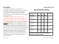
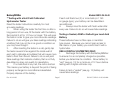
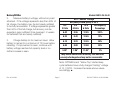
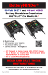
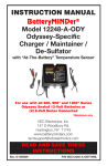
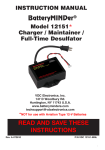
BatteryMINDer INSTRUCTIONS Models OBD12-24-36-48 BatteryMINDer® Models OBD-12, -24, -36 & -48 OnBoard Battery Restorer-Conditioners With Battery and Charging System Indicator VDC Electronics, Inc. 147D Woodbury Rd. Huntington, NY 11743 www.batteryminders.com [email protected] READ AND SAVE THESE INSTRUCTIONS Rev. H-041409 Rev. H-041409 Page 1 ` P/N VDC OBD12-24-36-48-MNL P/N VDC OBD12-24-36-48-MNL Models OBD12-24-36-48 BatteryMINDer Table of Contents General ..................................................................................................................................................................... 3 Qualifying Your Battery............................................................................................................................................ 4 Components & Descriptions .................................................................................................................................... 8 Auxiliary charger connector.................................................................................................................................... 9 Installing the Restorer-Conditioner ....................................................................................................................... 10 Battery Setup Configurations ................................................................................................................................. 11 Operating the Restorer-Conditioner ....................................................................................................................... 12 Troubleshooting ...................................................................................................................................................... 12 Battery and Charging System Tester ..................................................................................................................... 13 Operation .......................................................................................................................................................... 13 To Test Battery .................................................................................................................................................. 13 To Test Alternator / Charging System .............................................................................................................. 14 Spike Surge Protector ...................................................................................................................................... 14 LED Battery & Alternator Voltage Test Indications ................................................................................................ 15 Specifications ......................................................................................................................................................... 16 Our Guarantee and Warranty Conditions ............................................................................................................... 17 For Repair or Replacement..................................................................................................................................... 18 Rev. H-041409 Page 2 ` P/N VDC OBD12-24-36-48-MNL Models OBD12-24-36-48 BatteryMINDer General The BatteryMINDer® OnBoard Battery RestorerConditioners are designed to desulfate your batteries while you are operating your vehicle. The units utilize patented technology to produce a wide range of high frequency pulses known as RFP™ (Random Frequency Pulsation) designed to dissolve both old and newly formed sulfate. RFP™ technology, sweeps the entire frequency range known to cause sulfation crystals to resonate and then safely dissolve them. Sulfuric acid, the main component in the sulfate crystals, safely returns to the battery’s electrolyte. The Specific Gravity (S.G.) of the electrolyte is now higher and able to generate more electrical energy-storage capacity than the previously sulfated batteries. Additional advantages of using sulfation-free batteries include extended alternator and belt life, as the vehicle’s charging system no longer needs to work as hard trying to charge batteries that will not accept Rev. H-041409 high alternator output current due to sulfation buildup. Better fuel economy can also be expected, as much lower output current is now demanded from the alternator to keep clean, sulfate-free batteries fully charged. Lower alternator output current translates to lower engine level. Each of the BatteryMINDer On-Board RFP™ Battery Restorer-Conditioners can serve up to six batteries at a time. Thus, even large commercial vehicles, boats and commercial equipment require only one unit per system. Units are effective on all brands / types of batteries, including Maintenance-free, Gel, AGM, Deep Cycle, Sealed, and Free-electrolyte. Installation is a simple two wire hook-up to just one (1) battery or two (2) if using 6-volt batteries in series. The units stop working shortly after you turn your engine off. They do not use any power while your vehicle is turned off and very little when vehicle is running. ■ Page 3 ` P/N VDC OBD12-24-36-48-MNL Models OBD12-24-36-48 BatteryMINDer QUALIFYING YOUR BATTERY: Preliminary Requirements To confirm your battery’s condition before using your Battery Restorer-Conditioner (in order to prove the effect of the Battery Restorer-Conditioner) please take the following suggestions. The time it will take will be very worthwhile. If you experience any problems, or are not sure of how to properly use or connect your BatteryMINDer, please e-mail our technical support at: techsupport@vdcelectronics. com or call our toll-free technical support line 800379-5579 x206 (Eastern Time). Be certain to leave your phone number with the area code, time zone and the best time to call. To gain the best result from your new Battery Restorer-Conditioner and to maximize the life and performance of your batteries we strongly recommend you qualify (test) your batteries before attempting to either charge-maintain or desulfate them. Remember, even if you just purchased a “new” battery it may have been subjected to Rev. H-041409 conditions that have caused “sulfation” such as high temperature (>=80°) and/or allowed to self-discharge to 2.06 Volts/Cell or lower. NOTE: If your battery is new and you are certain it was not subject to conditions that could have caused sulfation, even before you purchased it, then you can disregard our recommendations for qualifying / testing your battery, before using the BatteryMINDer. Testing a Filler Cap or Manifold-type Lead Acid Battery 1. Carefully remove all caps or manifold-type covers from your battery. 2. Check the water-liquid electrolyte level. If the level is low or has ever been below top of plates, severe lead plate sulfation has taken place. Significant recharge/reconditioning time is needed to restore these plates to a condition where the battery can be expected to function normally. 3. Refill each cell with distilled water only to the liquid level indicator found in each cell. Page 4 ` P/N VDC OBD12-24-36-48-MNL Models OBD12-24-36-48 BatteryMINDer 4. Recharge the battery to ensure that it is completely charged as possible before you determine its condition. Allow battery to “rest”* overnight for a minimum of 12 hours before testing with a temperature compensated hydrometer and/or digital type voltmeter only. * “RESTED” = a battery that has been as fully charged as possible, using a 3 stage charger or your alternator and left disconnected from charger or any type load for a minimum of 12 hours before testing. 5. If the BatteryMINDer battery condition LED lights YELLOW (single battery) or no balls float in one or more cells, your battery may be too far gone to be fully desulfated. Use a hot/cold calibrated hydrometer tester for the most accurate results** (see next page) if you see an increase in the Specific Gravity (SG) or voltage indicating that there is an improvement in the battery’s condition, continue desulfating for an additional 72 hours and retest the battery. Continue this process until the SG or voltage readings no longer increase. Rev. H-041409 Page 5 OCV = Open Circuit No Load Voltage Temp. Compensated Hydrometer - meter or 4 ball type 6-V 3 cells 8-V 4 cells 12-V 6 cells Full Capacity Percentage 1.270 (4 Balls floating) 6.3V 8.4V 12.6V 100% 1.250 (3 Balls floating) 6.18 8.26 12.4 75% 1.190 (2 Balls floating) 6.09 8.13 12.2 50% 1.150 (1 Balls floating) 6.0 8.0 12.0 25% 1.120 (0 Balls floating) 5.881 7.841 11.81 0% May denote shorted cell or battery that has been severely discharged and may not be recoverable 1 ` P/N VDC OBD12-24-36-48-MNL Models OBD12-24-36-48 BatteryMINDer **Testing with a Hot/Cold Calibrated Hydrometer Tester Read the tester instructions carefully for most accurate readings. 1. When using the tester the first time or after a long period of non-use, fill the tester with the battery fluid and let it sit for 1/2 hour or longer. This will soak the balls in order to give you more accurate readings. Failure to do so will give you false readings indicating a battery that may not be in as good a condition as you may have thought. 2. After inserting the tester in a cell, gently tap the tester several times against the inside wall of each cell to dislodge air bubbles that will cause more balls to float than should. Failure to do so will yield false readings that indicate a battery that is not fully desulfated or does not qualify for desulfation. 3. If no balls float in any cell, the cell is shorted. This means your battery is beyond the point of being properly recharged or reconditioned-desulfated. Properly dispose of the battery. Rev. H-041409 If each cell floats two (2) or more balls (or 1190 on gauge-type), your battery can be desulfatedreconditioned. 4. Always rinse the tester with fresh water after every use. Failure to do so will cause false readings. Testing a Sealed, AGM or Gelled-type Lead Acid Battery These batteries have no filler caps or manifoldtype covers. Because you cannot gain access to the interior of your battery you cannot test it with a hydrometer. USE A DIGITAL VOLTMETER ONLY: 1. Recharge the battery with the BatteryMINDer to ensure it is as completely charged as possible, before you determine its condition. Allow battery to “rest” (see pg. 13) for a minimum of 12 hours before testing with a digital voltmeter only. Failure to test a “rested” (see pg. 13) battery will cause false readings. Page 6 ` P/N VDC OBD12-24-36-48-MNL Models OBD12-24-36-48 BatteryMINDer 2. Measure battery’s voltage, without any load attached. If the voltage represents less than 50% of full charge, the battery may be too heavily sulfated to be fully recoverable. If voltage represents greater than 50% of the full charge, full recovery can be expected, given sufficient time (average 1-2 weeks for batteries that are heavily sulfated). 6-V 3 Cells 3. Charge battery to its maximum level. Allow battery to remain for a minimum of 72 hours before retesting. If improvement is seen, continue until battery voltage reaches full capacity level or no further increase is seen. OCV -“Rested” Voltage Gel (volts) & AGM (volts) @ 26°C 8-V 12-V Full Capacity 4 Cells 6 Cells Percentage 6.42 8.56 12.85 100% 6.33 8.43 12.65 75% 6.18 8.23 12.35 50% 6.00 8.00 12.00 25% 5.90* 7.86* 11.80* 0% *May denote shorted cell or battery that has been severely discharged and may not be recoverable Note: OPTIMA brand “Yellow Top” starter/deep cycle batteries have a fully charged “resting” voltage of 13.1 (OCV). Increase-Decrease above values accordingly. ■ Rev. H-041409 Page 7 ` P/N VDC OBD12-24-36-48-MNL Models OBD12-24-36-48 BatteryMINDer 9 1 (back) 6 6 2 3 5 4 7 Components & Descriptions 8 Rev. H-041409 Page 8 ` P/N VDC OBD12-24-36-48-MNL Models OBD12-24-36-48 BatteryMINDer 1. 2. 3. 4. 5. LED (Light Emitting Diodes) Indicators (pgs. 11 - 13) Push To Test Button (pg. 12) Positive Lead w/Ring Terminal (pg. 10, 11) Negative Lead w/Ring Terminal (pg. 10, 11) Replaceable Fuse (10 Amps) (pg. 10) 6. 7. 8. 9. Mounting Tabs (2) (pg. 10) Auxiliary Charger Input Cord & Plug (pg. 9, 10) Plug Cover (pg. 9, 10) Velcro loop-lock adhesives (pg. 10) Auxiliary charger connector All OBD Model units are equipped with an auxiliary connector plug (charger input cord and plug) designed to allow a battery charger/maintainer to easily be attached to each unit, providing the voltage, polarity and plug type of the particular charger is the same*. It must never be used for any other purpose as the polarity of the connector may be different from the product you are plugging in. This could cause a short circuit or damage the unit, voiding the guarantee and warranty. Note: RED LED Fault Indicator will light if a device with incorrect polarity or fault is plugged into the Auxiliary charger connector. *Model OBD-12 is designed to be attached to one of VDC Electronics’ maintenance type chargers, such as the BatteryKeeper model 12612 or BatteryMINDer Models 12248, 12112, 12117. Model OBD-24 is also designed to be attached to a VDC Electronics’ maintenance type charger, namely the BatteryMINDer Model 24041. ■ Rev. H-041409 Page 9 ` P/N VDC OBD12-24-36-48-MNL Models OBD12-24-36-48 BatteryMINDer Installing the Battery Restorer-Conditioner Before you install the OnBoard Battery RestorerConditioner, turn the engine off. Mount the unit in a convenient place close to or directly on the battery. You can either mount the unit using screws (not supplied) or the Velcro loop-lock adhesives (supplied). Do not use screws of any kind if mounting Note: Your OBD is equipped with a replaceable Ten (10) Amp flat type automotive fuse. Never replace with a higher rated fuse or a hazardous condition may exist. ■ the unit directly on the battery. When using screws to mount unit on other surfaces be very careful of the length of the screws to avoid puncturing hidden wires or other sensitive components. 1. Find a safe and convenient place to attach the unit. Drill the holes for the screws (not supplied) or clean surface for Velcro fasteners. 2. Attach ring terminal on RED wire to the positive (+) clamp, threaded studs or side posts of your battery (depending on type of battery). 3. Attach the ring terminal on the black wire to the negative (-) clamp, threaded studs or side posts depending on your battery type. Rev. H-041409 Page 10 ` P/N VDC OBD12-24-36-48-MNL Models OBD12-24-36-48 BatteryMINDer MODEL OBD-12 12-V MODEL OBD-24 24-V MODEL OBD-36 36-V Rev. H-041409 MODEL OBD-48 48-V Page 11 ` P/N VDC OBD12-24-36-48-MNL Models OBD12-24-36-48 BatteryMINDer Operating the Battery Restorer-Conditioner After you have installed the Battery RestorerConditioner start your vehicle and allow it to idle for 2-3 minutes. The GREEN LED marked DESULFATING (blinking) will then begin blinking. Your battery is now being desulfated continuously, as long as your engine is running and your alternator is putting current into your battery. When you shut off your engine, the unit continues operating until your battery’s voltage returns to standard voltage levels. It will then shut off with no LED Indicators remaining on. Troubleshooting If the GREEN LED Indicator does not start blinking within 2 minutes of turning the engine on, check the polarity of the wires. The RED wire connects to the positive clamp on the battery and the black wire to the negative clamp. ■ Rev. H-041409 Page 12 ` P/N VDC OBD12-24-36-48-MNL Models OBD12-24-36-48 BatteryMINDer Battery and Charging System Tester Although very simple, this tester can accurately detect the condition of your battery as well as indicating whether your alternator or charging system is functioning sufficiently to recharge your battery. However, you must adhere to the instructions below to ensure you will get accurate readings. ■ Operation Note: For the most accurate readings always allow your battery to “Rest”* for a minimum of 12 hours, i.e. without charging or discharging or running your engine. Further test battery only with engine and all accessories and lights turned off. Test alternator / charging system only when engine is running and without lighting/accessories turned on. *”RESTED” = a battery that has been as fully charged as possible, using your vehicle’s alternator or a 3-stage charger. When using a charger be sure to disconnect unit from the charger and any type load for a minimum of 12 hours before testing. Rev. H-041409 To Test Battery (Engine and ALL power using lighting or accessories must be off for accurate readings • Press the PUSH to TEST button and hold down while viewing the LED indicators NO LEDs are lit = Battery has LESS THAN VOLTAGE (may be dead, shorted or severely discharged) Have battery load tested or recharge and retest. RED LED lit = POOR = Volts = Battery may be, shorted, or deeply discharged. If in doubt replace. YELLOW = FAIR = Volts (Both RED & YELLOW LED’s will light) = Battery may be shorted or discharged and unable to start your vehicle. Also check charging system GREEN = GOOD = Volts (All 3 LED’s will light) = Battery is “healthy” Represents Voltage specific to your OBD model. See Table for each model on page 15. ■ Page 13 ` P/N VDC OBD12-24-36-48-MNL Models OBD12-24-36-48 BatteryMINDer To Test Alternator / Charging System (Engine MUST be Running): • Press the PUSH to TEST button and hold down while viewing the LED indicators • GREEN LED marked Alternator should be lit. ALL four LEDs should light. If it does not show GREEN, Alternator / charging system is faulty and must be checked / repaired. Note: All four (4) test LED Indicators will light if Alternator is OK. ■ etc., from momentary voltage surges during “jump starting” or external battery charging. As there are many different component, accessories and systems and the amount of voltage surges cannot be fully determined, we cannot guarantee total 100% protection in all installations. Therefore, always be very careful to follow the jumper cable manufacturer’s safety and installation – connection instructions. ■ Spike Surge Protector Many times when using battery “Jumper Cables” a voltage surge (spike) is created when attaching the cables to your battery or the second battery system involved. Your OBD unit is equipped with a voltage spike protector designed to shield sensitive engine computer system components from the harmful affects of these surges. In addition, it will also protect plug-in 12-volt accessories such as your radar detector, cellular phone, personal computer, Rev. H-041409 Page 14 ` P/N VDC OBD12-24-36-48-MNL Models OBD12-24-36-48 BatteryMINDer LED Battery & Alternator Voltage Test Indications POOR FAIR GOOD GOOD-ALTc LED COLORS VOLTAGE OBD-12 11.2 – 12.3 11.8 – 12.3 12.3 – 12.8 13.2 – 14.2 <11.2* OBD-24 22.4 – 23.6 23.6 – 24.6 24.6 – 25.6 26.4 – 28.4 <22.4** OBD-36 33.6 – 36.9 35.4 – 36.9 36.9 – 38.4 36.6 – 42.6 <33.6*** OBD-48 44.8 – 49.2 47.2 – 49.2 49.2 – 51.2 52.8 – 56.8 <44.8**** *NO LEDs are lit = Battery has LESS THAN 11.2 VOLTS (see page 13) **NO LEDs are lit = Battery has LESS THAN 22.4 VOLTS (see page 13) ***NO LEDs are lit = Battery has LESS THAN 33.6 VOLTS (see page 13) ****NO LEDs are lit = Battery has LESS THAN 44.8 VOLTS (see page 13) cAll (4) LEDs are lit, if alternator output is high enough to charge battery, when required. Rev. H-041409 Page 15 ` P/N VDC OBD12-24-36-48-MNL Models OBD12-24-36-48 BatteryMINDer Meets watertight specifications JIS IP66 Weight : 8 oz. Size: 5.7” L x 2.25” W x 1.25“ H ■ AMPLITUDE Specifications For 12-V, 24-V, 36-V & 48-V (depending on model) battery systems only. Draws no current when engine-system is shut off. FREQUENCY Desulfation Waveform (typical) Full Time Desulfation output pulse peak current control lp-p....8 ±3 Adc Full Time Desulfation output PWM frequency...........................50 ±5 Hz Full Time Desulfation duty........................................................0.2% Rev. H-041409 Page 16 ` P/N VDC OBD12-24-36-48-MNL Models OBD12-24-36-48 BatteryMINDer Our Guarantee and Warranty Conditions ONE (1) YEAR 100% UNCONDITIONAL MONEY BACK GUARANTEE: BatteryMINDer OnBoard Battery RestorerConditioners are guaranteed to perform as claimed, or we will refund your full purchase price including all taxes, shipping or handling cost applicable to the purchase. Unit must be returned with Proof of Purchase directly to VDC Electronics, Inc., not to the dealer from which it was purchased. Physical damage to the unit will limit this guarantee. 5-YEAR LIMITED WARRANTY VDC Electronics, Inc. warrantees this product for FIVE (5) years from date of purchase at retail against defective materials or workmanship. It will be repaired or replaced at no charge providing it is returned to VDC Electronics, Inc., freight prepaid together with Proof of Purchase. We make no warranty other than this limited warranty and expressly exclude any implied warranty including any warranty for consequential damages. (This limited warranty is not transferable.) Return unit to: VDC Electronics, Inc., 147 D Woodbury Road Huntington, NY 11743 Allow up to ten (10) business days for repair or replacement plus shipping time. ■ Rev. H-041409 Page 17 ` P/N VDC OBD12-24-36-48-MNL Models OBD12-24-36-48 BatteryMINDer For Repair or Replacement In the event that you believe your product may be defective, you MUST speak to a VDC Electronics technician at 1-800-379-5579 x206 (ET) before proceeding further. If after speaking with our tech support personnel it is necessary to return the unit, you MUST request an RMA number. VDC Electronics, Inc. Returns Department Attn: RMA # (Enter Your RMA# Here) 147D Woodbury Rd. Huntington, NY 11743 All returns must be authorized by VDC Electronics. Items must be returned within 10 days after receiving your Return Merchandise Authorization number and must be packed in the original packaging with manual and all connectors included. Your Return Merchandise Authorization number must be shown on the return shipping label as follows: Rev. H-041409 Page 18 ` P/N VDC OBD12-24-36-48-MNL Models OBD12-24-36-48 BatteryMINDer Rev. H-041409 Page 19 ` P/N VDC OBD12-24-36-48-MNL Models OBD12-24-36-48 BatteryMINDer Rev. H-041409 Page 20 ` P/N VDC OBD12-24-36-48-MNL