1
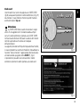
Libretto uso e manutenzione
Owner's manual
Manuel d'utilisation et entretien
Anleitungs-und Instandhaltungsheft
DUCATIMONSTER
S4Rs
Libretto uso e manutenzione
I
DUCATIMONSTERS4Rs
1
I
2
Siamo lieti di darti il benvenuto tra i Ducatisti e ci
complimentiamo con Te per l’ottima scelta effettuata.
Crediamo che oltre ad usufruire della tua nuova Ducati
come mezzo di normale spostamento, la utilizzerai per
effettuare viaggi anche lunghi, che la Ducati Motor Holding
S.p.A. Ti augura siano sempre piacevoli e divertenti.
Nel continuo sforzo di fornire un’assistenza sempre
migliore, la Ducati Motor Holding S.p.A. Ti consiglia di
seguire attentamente le semplici norme qui riportate,
in particolare per quanto concerne il rodaggio. Avrai così la
certezza che la tua Ducati sia sempre in grado di regalarti
grandi emozioni.
Per riparazioni o semplici consigli, rivolgiti ai nostri centri di
assistenza autorizzata.
Inoltre abbiamo predisposto un servizio informazioni per
i ducatisti e gli appassionati, a tua disposizione per
suggerimenti e consigli utili.
Note
La Ducati Motor Holding S.p.A. declina qualsiasi
responsabilità per eventuali errori in cui può essere
incorsa nella compilazione del presente libretto. Tutte le
informazioni riportate si intendono aggiornate alla data di
stampa. La Ducati Motor Holding S.p.A. si riserva il diritto
di apportare qualsiasi modifica richiesta dallo sviluppo
evolutivo dei suddetti prodotti.
DUCATI LINEA DIRETTA
Attenzione
Questo libretto è parte integrante del motociclo e,
in caso di passaggio di proprietà deve essere consegnato
al nuovo acquirente.
Numero Verde
Per la sicurezza, la garanzia, l’affidabilità ed il valore del
motociclo Ducati usa solo ricambi originali Ducati.
800-553066
Buon divertimento!
3
I
I
SOMMARIO
Manopola girevole comando acceleratore 20
Leva comando freno anteriore 21
Pedale comando freno posteriore 22
Pedale comando cambio 22
Registrazione posizione pedale comando cambio 23
Registrazione posizione pedale comando freno
posteriore 24
Indicazioni generali 6
Garanzia 6
Simboli 6
Informazioni utili per viaggiare in sicurezza 7
Guida a pieno carico 8
Dati per l’identificazione 9
Elementi e dispositivi principali 25
Posizione sul motociclo 25
Tappo serbatoio carburante 26
Serratura sella e portacasco 27
Cavalletto laterale 28
Registri di regolazione ammortizzatore posteriore 29
Registri di regolazione forcella anteriore 30
Variazione assetto motociclo 32
Comandi per la guida 10
Posizione dei comandi per la guida del motociclo 10
Cruscotto 11
Il sistema immobilizer 14
Chiavi 14
Code card 15
Procedura di sblocco immobilizer tramite manopola acceleratore 16
Duplicazione delle chiavi 17
Interruttore d’accensione e bloccasterzo 18
Commutatore sinistro 19
Leva comando frizione 19
Commutatore destro 20
4
Norme d’uso 34
Precauzioni per il primo periodo d’uso del motociclo 34
Controlli prima dell’avviamento 36
Avviamento motore 37
Avviamento e marcia del motociclo 40
Frenata 40
Arresto del motociclo 41
Rifornimento carburante 41
Parcheggio 42
Accessori in dotazione 43
Operazioni d’uso e Manutenzione principali
Rimozione della vestizione 44
Sollevamento serbatoio carburante 45
Sostituzione del filtro aria 46
Controllo livello liquido di raffreddamento 47
Controllo livello fluido freni e frizione 48
Verifica usura pastiglie freno 49
Regolazione del cavo comando acceleratore 49
Lubrificazione delle articolazioni 50
Carica della batteria 51
Controllo tensione catena trasmissione 52
Lubrificazione della catena trasmissione 52
Sostituzione delle lampadine 53
Orientamento del proiettore 56
Pneumatici 58
Controllo livello olio motore 60
Pulizia e sostituzione candele 61
Pulizia generale 62
Lunga inattività 63
Avvertenze importanti 63
Caratteristiche tecniche
Ingombri (mm) 64
Pesi 64
Rifornimenti 65
Motore 66
Distribuzione 66
Prestazioni 67
Candele d’accensione 67
Alimentazione 67
44
Freni 67
Trasmissione 68
Telaio 68
Ruote 69
Pneumatici 69
Sospensioni 69
Impianto di scarico 70
Colori disponibili 70
Impianto elettrico 70
Promemoria manutenzioni periodiche
I
74
64
5
I
INDICAZIONI GENERALI
Garanzia
Nel Tuo interesse, a garanzia ed affidabilità del prodotto,
Ti consigliamo vivamente di rivolgerti ad un Concessionario
o ad un’Officina Autorizzata per qualsiasi operazione che
richieda particolare competenza tecnica.
Il nostro personale, altamente qualificato, dispone di
adeguate attrezzature per eseguire qualsiasi intervento a
regola d’arte utilizzando esclusivamente ricambi originali
Ducati che garantiscono la perfetta intercambiabilità,
buon funzionamento e lunga durata.
Tutti i motocicli Ducati sono corredati di Libretto di
Garanzia. La garanzia non verrà riconosciuta ai motocicli
impiegati in gare sportive. Durante il periodo di garanzia
nessun componente può essere manomesso, modificato
oppure sostituito con altro non originale, pena l’immediata
decadenza del diritto di garanzia.
6
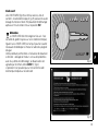
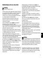
Simboli
La Ducati Motor Holding S.p.A. Ti invita a leggere
attentamente il seguente libretto al fine di imparare a
conoscere il Tuo motociclo. In caso di dubbi rivolgersi ad
un Concessionario o ad un’Officina Autorizzata. Le nozioni
che apprenderai si riveleranno utili durante i viaggi che
la Ducati Motor Holding S.p.A. Ti augura siano sereni e
divertenti e Ti permetteranno di mantenere inalterate
per lungo tempo le prestazioni del motociclo.
In questo libretto sono state riportate note informative con
significati particolari:
Attenzione
La non osservanza delle istruzioni riportate può
creare una situazione di pericolo e causare gravi lesioni
personali e anche la morte.
Importante
Esiste la possibilità di arrecare danno al motociclo
e/o ai suoi componenti.
Note
Ulteriori notizie inerenti l’operazione in corso.
Tutte le indicazioni relative a destro o sinistro si
riferiscono al senso di marcia del motociclo.
Informazioni utili per viaggiare in sicurezza
Attenzione
Leggere prima di usare la moto.
Molti incidenti sono spesso dovuti all’inesperienza nella
guida del motociclo. Non guidare mai senza patente;
per utilizzare il motociclo è necessario essere titolari di
regolare patente di guida.
Non prestare il motociclo a piloti inesperti o sprovvisti di
regolare patente di guida.
Il pilota e il passeggero devono indossare sempre un
abbigliamento adeguato e casco protettivo.
Non portare abiti o accessori svolazzanti che possono
impigliarsi nei comandi o limitare la visibilità.
Non avviare mai il motore in un ambiente chiuso. I fumi
di scarico sono velenosi e possono provocare perdita di
conoscenza o addirittura la morte in tempi brevi.
Il pilota e il passeggero devono appoggiare i piedi sulle
pedane ogni volta che il motociclo è in movimento.
Per essere pronto ad ogni cambiamento di direzione o ad
ogni variazione del fondo stradale, il pilota deve tenere
sempre le mani sul manubrio, mentre il passeggero deve
tenersi sempre con entrambe le mani nelle apposite
maniglie del telaio sotto la sella.
Attenersi alla legislazione e alle regole nazionali e locali.
Rispettare sempre i limiti di velocità dove indicati e
comunque non superare mai la velocità che le condizioni
di visibilità, di fondo stradale e di traffico consentono.
Segnalare sempre e con sufficiente anticipo, utilizzando gli
appositi indicatori di direzione, ogni svolta o cambiamento
di corsia.
Rendersi ben visibili evitando di viaggiare nelle
“aree cieche” dei veicoli che precedono.
Fare molta attenzione negli incroci, in corrispondenza
delle uscite da aree private o da parcheggi e nelle corsie
d’ingresso in autostrada.
Spegnere sempre il motore quando si fa rifornimento e
fare attenzione a non far cadere del carburante sul motore
o sul tubo di scarico.
Non fumare mai durante il rifornimento.
Durante il rifornimento si possono inalare vapori di
carburante nocivi alla salute. Se qualche goccia di
carburante dovesse cadere sulla pelle o sugli abiti, lavarsi
immediatamente con acqua e sapone e cambiare gli abiti.
Togliere sempre la chiave quando si lascia il motociclo
incustodito.
Il motore, i tubi di scarico e i silenziatori restano caldi a
lungo.
Attenzione
L’impianto di scarico può essere caldo, anche dopo lo
spegnimento del motore; prestare molta attenzione a non
toccare con nessuna parte del corpo l’impianto di scarico e
a non parcheggiare il veicolo in prossimità di materiali
infiammabili (compreso legno, foglie, ecc.).
Parcheggiare il motociclo in modo che non possa essere
urtato e utilizzando il cavalletto laterale.
Non parcheggiare mai su un terreno sconnesso o morbido,
in quanto il motociclo potrebbe cadere.
7
I
I
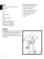
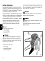
Guida a pieno carico
Questo motociclo è stato progettato per percorrere lunghi
tratti a pieno carico in assoluta sicurezza.
La sistemazione dei pesi sul motociclo è molto importante
per mantenere inalterati gli standard di sicurezza ed evitare
di trovarsi in difficoltà in caso di manovre repentine o
in tratti di strada sconnessa.
Informazioni sul carico trasportabile
Il peso complessivo del motociclo in ordine di marcia con
conducente, passeggero, bagaglio e accessori addizionali
non deve superare i:
390 Kg.
Cercare di disporre il bagaglio o gli accessori più pesanti in
posizione quanto più bassa possibile e possibilmente al
centro del motociclo.
Fissare saldamente il bagaglio alle strutture del motociclo;
un bagaglio non fissato correttamente può renderlo
instabile.
Non fissare elementi voluminosi e pesanti sulla testa di
sterzo o sul parafango anteriore in quanto causerebbero
una pericolosa instabilità del motociclo.
Non inserire parti da trasportare negli interstizi del telaio in
quanto potrebbero interferire con le parti in movimento del
motociclo.
Verificare che i pneumatici siano gonfiati alla pressione
indicata a pag. 58 e che risultino in buone condizioni.
8
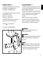
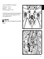
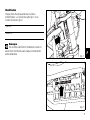
Dati per l’identificazione
Ogni motociclo Ducati è contraddistinto da due numeri di
d’identificazione, rispettivamente per il telaio (fig. 1) e per
il motore (fig. 2).
I
Telaio N.
Motore N.
Note
Questi numeri identificano il modello del motociclo e
sono da citare per la richiesta di parti di ricambio.
fig. 1
fig. 2
9
I
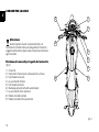
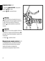
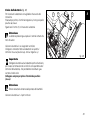
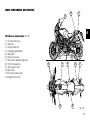
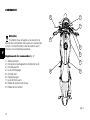
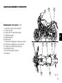
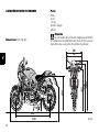
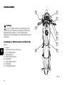
COMANDI PER LA GUIDA
4
1
7
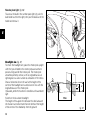
Attenzione
Questo capitolo illustra il posizionamento e la
funzione dei comandi necessari alla guida del motociclo.
Leggere attentamente quanto descritto prima di utilizzare
ogni comando.
3
6
5
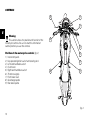
Posizione dei comandi per la guida del motociclo
(fig. 3)
1)
2)
3)
4)
5)
6)
7)
8)
9)
Cruscotto.
Interruttore d’accensione e bloccasterzo a chiave.
Commutatore sinistro.
Leva comando frizione.
Commutatore destro.
Manopola girevole comando acceleratore.
Leva comando freno anteriore.
Pedale comando cambio.
Pedale comando freno posteriore.
2
8
9
fig. 3
10
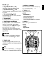
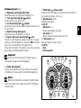
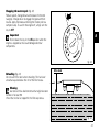
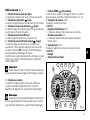
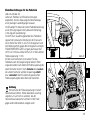
Cruscotto (fig. 4)
1) Spia proiettore abbagliante
(blu).
Si accende per indicare la luce abbagliante accesa.
2) Spia indicatori di direzione
(verde).
Si accende e lampeggia quando un indicatore di direzione
è in funzione.
3) Spia riserva carburante
(gialla).
Si accende quando il serbatoio è in riserva, sono rimasti
circa 3,5 litri di carburante.
4) Spia folle N (verde).
Si accende quando il cambio è in posizione di folle.
5) Spia pressione olio motore
(rossa).
Si accende per indicare una pressione dell’olio motore
insufficiente. Deve accendersi quando si sposta
l’interruttore d’accensione su ON, ma deve spegnersi
alcuni secondi dopo l’avvio del motore.
Può succedere che si accenda brevemente in caso di
motore molto caldo, dovrebbe spegnersi quando i numeri
di giri aumentano.
Importante
Non utilizzare il motociclo quando la spia rimane
accesa in quanto si potrebbe danneggiare il motore.
7) Spia EOBD
(giallo ambra).
Indica il blocco motore accendendosi. Si spegne dopo
alcuni secondi (normalmente 1,8 - 2 sec.).
8) Tachimetro (km/h).
Indica la velocità di marcia.
a) LCD (1):
- Contachilometri (km).
Indica la distanza totale percorsa.
- Contachilometri parziale (km).
Indica la distanza percorsa dall’ultimo azzeramento.
9) Contagiri (min-1).
Indica il numero di giri al minuto del motore.
b) LCD (2):
- Orologio
- Temperatura olio
1
4
5
3
9
8
6) Spia giallo ambra
Si accende e lampeggia quando il motociclo è in sosta
(Immobilizer attivo), viene anche utilizzata come diagnostica
dell’immobilizer.
Note
Una volta attivato l’immobilizer, la spia lampeggia per
24 ore dopo di che si spegne, lasciandolo comunque attivo.
2
I
7
a
6
b
fig. 4
11
I
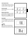
Funzioni delle unità LCD
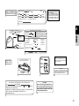
All'accensione (chiave da OFF a ON) il cruscotto esegue
un Check di tutta la strumentazione (lancette, display, spie)
(fig. 5 e fig. 6).
OFF
Funzioni dell’unita LCD (1)
Premendo il pulsante (B, fig. 6) con chiave ON si alterna
la visualizzazione del contachilometri parziale e di quello
totale.
Azzeramento contachilometri parziale
Tenendo premuto il pulsante (B, fig. 6) per più di 2 secondi
quando è nella funzione TRIP (contachilometri parziale),
si otterrà l'azzeramento nel display (LCD 1).
fig. 5
Funzioni dell’unita LCD (2)
Premendo il pulsante (A, fig. 6) con chiave ON si visualizza
l'orologio e la temperatura dell’acqua.
Regolazione orologio
Premere il pulsante (B, fig. 6) per almeno 2 secondi.
Regolare AM/PM premendo il pulsante (A, fig. 6).
Premere il pulsante (B) per passare alla regolazione
dell’ora. Premere (A) ripetutamente per modificare
l'indicazione dell'ora. Premere il pulsante (B, fig. 6)
per passare alla regolazione dei minuti.
Premere il pulsante (A) per avanzare i minuti; tenendo
premuto per più di 5 secondi l'indicazione cambia più
velocemente. Premere il pulsante (B) per uscire dal modo
di regolazione.
12
CHECK
1
A
B
2
fig. 6
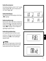
Funzione temperatura acqua
Quando la temperatura dell'acqua va sotto i 40 °C /104 °F
viene indicata sul display la scritta “LO” e sopra 120 °C/
248 °F “HI”.
I
Funzione spia livello carburante
Quando si accende la spia della riserva viene indicato sul
Display la scritta “FUEL”.
Funzione indicatore manutenzione
Dopo i primi 1000 Km / 621 mi e successivamente ogni
10.000 Km / 6210 mi ad ogni chiave ON per un tempo
uguale a 5 secondi viene visualizzata nel display la scritta
“MAInt” che sta ad indicare la scadenza del tagliando di
manutenzione periodica.
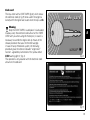
Funzione retroilluminazione
Se si preme il tasto (B, fig. 6) entro 5 secondi con la chiave
in posizione ON, ad ogni pressione sul detto pulsante si
avrà una variazione dell'intensità luminosa del cruscotto.
Attenzione
Intervenire sul cruscotto esclusivamente a veicolo
fermo. Non intervenire per nessun motivo sul cruscotto
mentre si è alla guida del veicolo.
13
I
Il sistema immobilizer
Per aumentare la protezione contro il furto, il motociclo
è dotato di un sistema elettronico di blocco del motore
(IMMOBILIZER) che si attiva automaticamente ogni volta
che si spegne il quadro.
Ogni chiave racchiude infatti nell’impugnatura, un
dispositivo elettronico che ha la funzione di modulare il
segnale emesso all’atto dell’avviamento da una speciale
antenna incorporata nel commutatore. Il segnale modulato
costituisce la “parola d’ordine”, sempre diversa ad ogni
avviamento, con cui la centralina riconosce la chiave e solo
a questa condizione, consente l’avviamento del motore.
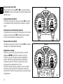
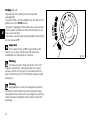
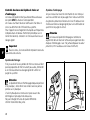
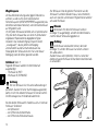
Chiavi (fig. 7)
Con il motociclo vengono consegnate:
- n°1 chiave A (ROSSA)
- n°2 chiavi B (NERE)
La chiave A svolge le stesse funzioni delle chiavi B, in più
permette di cancellare e riprogrammare, in caso di
necessità, altre chiavi nere.
Note
Con le tre chiavi viene consegnata anche una
piastrina (1) con il numero di identificazione delle chiavi.
Attenzione
Separare le chiavi e conservare la piastrina (1), e
la chiave A, in un luogo sicuro.
Inoltre è consigliabile utilizzare una sola delle due chiavi
nere per l’avviamento del motociclo.
B
Attenzione
La chiave rossa A è ricoperta da un cappuccio di
gomma per essere conservata in perfette condizioni,
evitando il contatto con altre chiavi. Non rimuovere questa
protezione se non in caso di necessità.
A
Le chiavi B, sono quelle di normale uso e servono per:
- l’avviamento.
- il tappo del serbatoio carburante.
- la serratura della sella.
1
14
fig. 7
Code card
Insieme alle chiavi viene consegnata una CODE CARD
(fig. 8) sulla quale è riportato: il codice elettronico (A, fig. 9),
da utilizzare in caso di blocco motore e quindi mancata
accensione dopo il key-on.
I
Attenzione
La CODE CARD deve essere conservata in luogo
sicuro. È consigliabile che l’utilizzatore abbia sempre
con sé il codice elettronico riportato sulla CODE CARD,
nell’eventualità di dover effettuare lo sblocco del motore
tramite la procedura che utilizza la manopola
dell’acceleratore.
La seguente procedura offre quindi la possibilità all’utente,
in caso di problemi al sistema immobilizer, di disabilitare la
funzione “blocco motore” rappresentata dall’accensione
simultanea della spia giallo ambra EOBD (7, fig. 4).
L’operazione è possibile solo conoscendo il codice
elettronico (electronic code) riportato sulla code card.
fig. 8
A
B
fig. 9
15
I
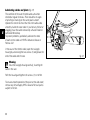
Procedura di sblocco immobilizer tramite
manopola acceleratore
1) Portare la chiave su ON e ruotare completamente la
manopola acceleratore mantenendola ruotata.
La spia EOBD (7, fig. 4) si spegne dopo un tempo
prestabilito di 8 secondi.
2) Allo spegnimento della spia EOBD rilasciare la
manopola.
3) La spia EOBD si riaccenderà lampeggiando. Occorre ora
inserire il codice elettronico di sblocco riportato sulla
CODE CARD consegnata al cliente all'atto della consegna
della moto da parte del concessionario.
4) Contare un numero di lampeggi della spia EOBD pari alla
prima cifra del codice segreto.
Portare la manopola acceleratore in posizione tutta aperta
per 2 secondi, quindi rilasciare. Viene così riconosciuta
l'immissione di una cifra e la spia EOBD si accende e
rimane in questo stato per un tempo prestabilito di
4 secondi. Ripetere l'operazione fino all'introduzione
dell'ultima cifra.
Nel caso in cui non si compia nessuna operazione con
l'acceleratore, la spia EOBD pulserà per 20 volte, poi si
accenderà in modo fisso e la procedura dovrà essere
ripetuta dal punto (1).
5) Al rilascio della manopola acceleratore, in caso di codice
correttamente introdotto, la spia EOBD si accende in
modo lampeggiante per indicare l'avvenuto sblocco.
La spia ritorna in condizioni normali (spenta) dopo
4 secondi.
16
6) Se il codice NON è stato introdotto correttamente
la spia EOBD rimane accesa ed è possibile ripetere le
operazioni riportando la chiave su OFF e ripartendo dal
punto (1) per un numero illimitato di volte.
Note
Nel caso la manopola venga rilasciata prima del tempo
prestabilito, la spia si riaccende ed è necessario riportare
la chiave su OFF e ripetere la sequenza dal punto (1).
Funzionamento
Ogni volta che si ruota la chiave del commutatore da ON a
OFF, il sistema di protezione attiva il blocco motore.
All’avviamento del motore, ruotando la chiave da OFF
a ON:
1) se il codice viene riconosciuto, la spia (6, fig. 4), posta sul
quadro strumenti, emette un breve lampeggio; il sistema
di protezione ha riconosciuto il codice della chiave e
disattiva il blocco motore. Premendo il pulsante START
(2, fig. 12), il motore si avvia;
2) se la spia (6, fig. 4) o la spia EOBD (7, fig. 4) rimangono
accese, il codice non è stato riconosciuto. In questo caso
si consiglia di riportare la chiave in posizione OFF e poi di
nuovo in ON, se il blocco persiste, riprovare con l’altra
chiave in dotazione di colore nero. Se ancora non si riesce
ad avviare il motore, rivolgersi alla rete assistenziale
DUCATI.
3) Se la spia (6, fig. 4) rimane lampeggiante significa
che una segnalazione del sistema immobilizer è stata
ripristinata (ad esempio con la procedura di sblocco tramite
manopola). Ruotando la chiave in posizione OFF e
nuovamente su ON la spia immobilizer dovrebbe
riprendere il suo normale funzionamento (vedi punto 1).
Duplicazione delle chiavi
Quando il cliente necessita di chiavi supplementari, deve
rivolgersi alla rete assistenziale DUCATI e portare con sé
tutte le chiavi ancora a sua disposizione e la CODE CARD.
La rete assistenziale DUCATI, effettuerà la memorizzazione
(fino ad un massimo di 8 chiavi) di tutte le chiavi nuove e di
quelle già in possesso.
La rete assistenziale DUCATI, potrà richiedere al cliente
di dimostrare di essere il proprietario del motociclo.
I codici delle chiavi non presentate durante la procedura
di memorizzazione, vengono cancellati dalla memoria,
a garanzia che le chiavi eventualmente smarrite non siano
più in grado di avviare il motore.
Note
In caso di cambio di proprietario del motociclo,
è indispensabile che il nuovo proprietario entri in possesso
di tutte le chiavi e della CODE CARD.
Attenzione
Urti violenti potrebbero danneggiare i componenti
elettronici contenuti nella chiave.
Durante la procedura utilizzare sempre la stessa chiave.
L’utilizzo di chiavi diverse potrebbe impedire al sistema di
riconoscere il codice della chiave inserita.
17
I
Interruttore d’accensione e bloccasterzo (fig. 10)
È sistemato davanti al serbatoio ed è a quattro posizioni:
Note
Per portare la chiave in queste ultime due posizioni è
necessario spingerla e quindi ruotarla. Nelle posizioni (B),
(C) e (D) la chiave può essere estratta.
O
FF
ON
C
N
P
O
K
ON: abilita il funzionamento di luci e motore;
OFF: disabilita il funzionamento di luci e motore;
LOCK: lo sterzo è bloccato;
P: luce di posizione e bloccasterzo.
LO C
A)
B)
C)
D)
A
B
PU SH
I
I G NI
TI
D
fig. 10
18
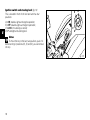
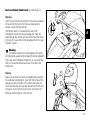
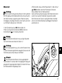
Commutatore sinistro (fig. 11)
1) Deviatore, comando selezione luce, a due posizioni:
posizione
= luce anabbagliante accesa;
posizione
= luce abbagliante accesa.
2) Pulsante
= indicatore di direzione a tre posizioni:
posizione centrale = spento;
posizione
= svolta a sinistra;
posizione
= svolta a destra.
Per disattivare l’indicatore, premere sulla levetta di
comando una volta che è ritornata al centro.
3) Pulsante
= avvisatore acustico.
4) Pulsante
= lampeggio abbagliante.
5
4
Leva comando frizione (fig. 11)
La leva (5) che aziona il disinnesto della frizione, è dotata
di un pomello (6) per la regolazione della distanza tra la leva
stessa e la manopola, sul manubrio.
La distanza della leva è regolata da 10 scatti del pomello (6).
Ruotando in senso orario la leva si allontana dalla manopola.
Viceversa, ruotando il pomello in senso antiorario,
si avvicina.
Quando la leva (5) viene azionata si interrompe la
trasmissione dal motore al cambio e quindi alla ruota
motrice. Il suo utilizzo è molto importante in tutte le fasi
di guida del motociclo, specialmente nelle partenze.
Attenzione
La regolazione della leva frizione e freno, va
effettuata a motociclo fermo.
6
Importante
Un corretto utilizzo di questo dispositivo prolungherà
la vita del motore evitando danni a tutti gli organi di
trasmissione.
Note
È possibile avviare il motore con il cavalletto aperto
ed il cambio in posizione di folle, oppure con la marcia
del cambio inserita, tenendo tirata la leva della frizione
(in questo caso il cavalletto deve essere chiuso).
1
3
2
fig. 11
19
I
I
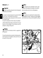
Commutatore destro (fig. 12)
1) Interruttore ARRESTO MOTORE, a due posizioni:
posizione
(RUN) = marcia;
posizione
(OFF) = arresto del motore.
Attenzione
Questo interruttore serve soprattutto nei casi di
emergenza quando è necessario spegnere velocemente
il motore. Dopo l’arresto riportare l’interruttore in
posizione
per poter procedere all’avviamento del
motociclo.
Importante
Viaggiare con la luce accesa, spegnere il motore con
l’interruttore (1) e lasciare la chiave d’accensione su ON
può causare l’esaurimento della batteria, in quanto la luce
rimane accesa.
2) Pulsante
= avviamento motore.
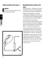
Manopola girevole comando acceleratore (fig. 12)
La manopola girevole (3), sul lato destro del manubrio,
comanda l’apertura delle farfalle del corpo farfallato.
Quando viene rilasciata, la manopola torna
automaticamente alla posizione iniziale di minimo.
20
1
2
3
fig. 12
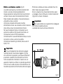
Leva comando freno anteriore (fig. 13)
Tirando verso la manopola girevole la leva (4) si aziona il
freno anteriore. È sufficiente un minimo sforzo della mano
per azionare questo dispositivo in quanto il funzionamento
è idraulico.
La leva di comando è dotata di un pomello (5) per la
regolazione della distanza della leva dalla manopola
sul semimanubrio.
La distanza della leva è regolata da 10 scatti del pomello (5).
Ruotando in senso orario la leva si allontana dalla manopola
acceleratore. Viceversa, ruotando il pomello in senso
antiorario, si avvicina.
Attenzione
Prima di utilizzare questi comandi leggere le istruzioni
riportate a pag. 40.
5
I
4
fig. 13
21
I
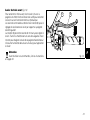
Pedale comando freno posteriore (fig. 14)
Per azionare il freno posteriore, premere il pedale (1)
verso il basso con il piede.
Il sistema di comando è di tipo idraulico.
1
Pedale comando cambio (fig. 15)
Il pedale comando cambio ha una posizione di riposo
centrale N con ritorno automatico e due movimenti:
in basso = spingere il pedale verso il basso per innestare la
1a marcia e per scalare a una marcia inferiore. Con questa
manovra la spia N sul cruscotto si spegne;
in alto = sollevare il pedale per innestare la 2a marcia e
successivamente la 3a, 4a, 5a e 6a marcia.
Ad ogni spostamento del pedale corrisponde solo un
cambio marcia.
fig. 14
6
5
4
3
2
N
1
22
fig. 15
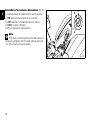
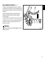
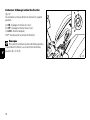
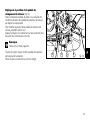
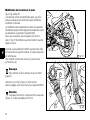
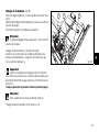
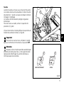
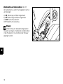
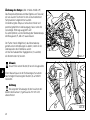
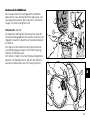
Registrazione posizione pedale comando cambio
(fig. 16)
Per assecondare le esigenze di guida di ogni pilota è
possibile modificare la posizione della leva comando
cambio rispetto all’appoggiapiedi.
Per modificare la posizione della leva comando cambio
agire nel modo seguente:
Bloccare l’asta (1) utilizzando la presa chiave (2) e allentare
i controdadi (3) e (4).
I
Note
Il dado (3) ha un filetto sinistrorso.
Ruotare l’asta (1) facendo assumere al pedale cambio la
posizione desiderata.
Serrare contro l’asta entrambi i controdadi.
3
1
2
4
fig. 16
23
I
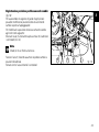
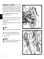
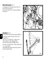
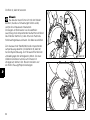
Registrazione posizione pedale comando freno
posteriore (fig. 17)
Per assecondare le esigenze di guida di ogni pilota è
possibile modificare la posizione della leva comando freno
posteriore rispetto all’appoggiapiedi.
Per modificare la posizione della leva comando freno
posteriore agire nel modo seguente:
Allentare il controdado (5).
Ruotare la vite (6) di registro corsa pedale fino a stabilire
la posizione desiderata.
Serrare il controdado (5).
Verificare, agendo a mano sul pedale, che questo presenti
un gioco di circa 1,5÷2 mm prima di iniziare l’azione
frenante.
Se così non risulta occorre modificare la lunghezza
dell’astina di comando della pompa nel modo seguente:
Allentare il controdado (7) sull’astina della pompa.
Avvitare l’astina (8) sulla forcella (9) per aumentare il gioco
o svitarla per diminuirlo.
Serrare il controdado (7) e verificare nuovamente il gioco.
24
9
7
8
6
5
fig. 17
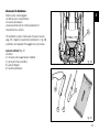
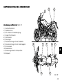
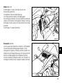
ELEMENTI E DISPOSITIVI PRINCIPALI
10
I
4
6
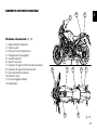
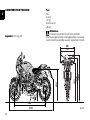
Posizione sul motociclo (fig. 18)
1) Tappo serbatoio carburante.
2) Serratura sella.
3) Perno per il cavetto portacasco.
4) Impugnatura per passeggero.
5) Cavalletto laterale.
6) Specchi retrovisori.
7) Dispositivi di registro ammortizzatore posteriore.
8) Dispositivi di registro forcella anteriore.
9) Asta sollevamento serbatoio.
10)Coperchio sella.
11)Leva ancoraggio serbatoio.
12)Catalizzatore.
5
12
1
8
11
7
2
9
3
fig. 18
25
I
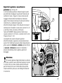
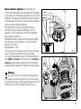
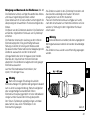
Tappo serbatoio carburante (fig. 19)
1/4
Apertura
Sollevare il coperchietto (1) di protezione ed inserire la
chiave nella serratura. Ruotare di 1/4 di giro la chiave
in senso orario per sbloccare la serratura.
Sollevare il tappo.
OPEN
0
1
Chiusura
Richiudere il tappo con la chiave inserita e premerlo
nella sede. Ruotare la chiave in senso antiorario fino
alla posizione originale ed estrarla.
Richiudere il coperchietto (1) di protezione serratura.
Note
È possibile chiudere il tappo solo con la chiave
inserita.
Attenzione
Dopo ogni rifornimento (vedi pag. 41) accertarsi
sempre che il tappo sia perfettamente posizionato e
chiuso.
26
fig. 19
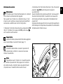
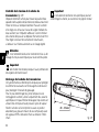
Serratura sella e portacasco (fig. 20 e fig. 21)
Apertura
Introdurre la chiave nella serratura, ruotarla in senso orario
per ottenere lo sganciamento della sella dal telaio.
Sfilare la sella dai fermi anteriori tirandola all’indietro.
Nella parte posteriore del vano sotto la sella si trova il
cavetto portacasco (1) (vedi pag. 43). Far passare il cavetto
nel casco ed inserire nel perno (2) l’estremità del cavetto.
Lasciare appeso il casco e rimontare la sella per fissarlo.
I
0
1
Attenzione
Questo dispositivo serve per la sicurezza del casco
quando il motociclo è parcheggiato. Non lasciare il casco
attaccato quando si viaggia; potrebbe interferire con le
operazioni di guida e causare la perdita di controllo del
motociclo.
Chiusura
Assicurarsi che tutti gli elementi siano correttamente
disposti e fissati nel vano sotto la sella. Inserire le estremità
anteriori del fondo sella sotto al cavallotto del telaio quindi
spingere sull’estremità posteriore della sella fino ad udire
lo scatto del chiavistello della serratura. Assicurarsi che la
sella sia saldamente fissata al telaio e rimuovere la chiave
dalla serratura.
fig. 20
1
2
fig. 21
27
I
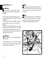
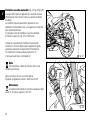
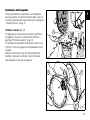
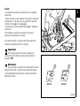
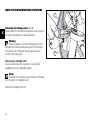
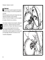
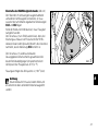
Cavalletto laterale (fig. 22)
Importante
Prima d’azionare il cavalletto laterale, accertarsi
dell’adeguata consistenza e planarità della superficie
d’appoggio.
Terreni molli, ghiaia, asfalto ammorbidito dal sole, ecc.,
possono infatti determinare rovinose cadute del motociclo
parcheggiato.
In caso di pendenza del suolo, parcheggiare sempre con
la ruota posteriore rivolta verso il lato in discesa della
pendenza.
Per impiegare il cavalletto laterale, premere con il piede
(tenendo il motociclo con entrambe le mani sul manubrio)
sulla stampella (1) accompagnandola fino al punto di
massima estensione. Inclinare il motociclo fino a portare
in appoggio il cavalletto al suolo.
Note
È consigliabile verificare periodicamente il corretto
funzionamento del sistema di trattenuta (costituito da due
molle a trazione una all’interno dell’altra) e del sensore di
sicurezza (2).
Note
È possibile avviare il motore con il cavalletto aperto
ed il cambio in posizione di folle, oppure con la marcia
del cambio inserita, tenendo tirata la leva della frizione
(in questo caso il cavalletto deve essere chiuso).
Attenzione
Non sostare seduti sul motociclo parcheggiato col
cavalletto laterale.
Per posizionare il cavalletto a “riposo” (posizione orizzontale),
inclinare il motociclo verso destra e contemporaneamente
sollevare con il piede la stampella (1).
2
1
fig. 22
28
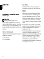
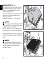
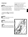
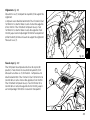
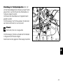
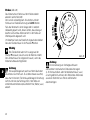
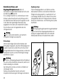
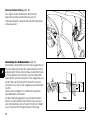
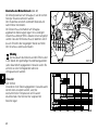
Registri di regolazione ammortizzatore
posteriore (fig. 23 e fig. 24)
L’ammortizzatore posteriore è dotato di registri esterni
per permettere di adeguare l’assetto del motociclo alle
condizioni di carico. Il registro (1) posto nella zona del
fissaggio inferiore dell’ammortizzatore al forcellone,
regola il freno idraulico nella fase di estensione (ritorno).
Il pomello (2) sul serbatoio d’espansione
dell’ammortizzatore regola il freno idraulico nella fase di
compressione. Ruotando in senso orario i pomelli (1 e 2)
si aumenta il freno, viceversa si diminuisce.
Taratura STANDARD: dalla posizione di tutto chiuso
ruotare il pomello (1) di 10 click e il pomello (2) di 12 click.
Precarico molla: 11 mm.
Le due ghiere (3), poste nella parte superiore
dell’ammortizzatore, registrano il precarico della molla
esterna. Per modificare il precarico della molla allentare la
ghiera superiore. Avvitando o svitando la ghiera inferiore
si aumenta o diminuisce il precarico. Impostato il
precarico desiderato serrare la ghiera superiore di
bloccaggio.
I
1
H
S
fig. 23
2
3
Attenzione
Per ruotare la ghiera di registro del precarico utilizzare
una chiave a settore. Usare particolare cautela per evitare
il rischio di ferirsi la mano urtando violentemente altre
parti del motociclo in caso il dente della chiave perda
improvvisamente la presa sul vano della ghiera durante
il movimento.
fig. 24
29
I
Attenzione
L’ammortizzatore contiene gas ad alta pressione e
potrebbe causare seri danni se smontato da persone
inesperte.
Se si intende trasportare passeggero e bagaglio,
precaricare al massimo la molla dell’ammortizzatore
posteriore per migliorare il comportamento dinamico
del motociclo ed evitare possibili interferenze col suolo.
Ciò può richiedere l’adeguamento della regolazione del
freno idraulico in estensione.
30
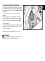
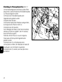
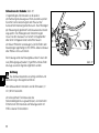
Registri di regolazione forcella anteriore
(fig. 25 - fig. 26)
La forcella del motociclo è regolabile sia nella fase di
estensione (ritorno) sia nella compressione degli steli.
La regolazione avviene per mezzo dei registri esterni a vite:
1) (fig. 25) per modificare il freno idraulico in estensione;
2) (fig. 25) per modificare il precarico delle molle interne;
3) (fig. 26) per modificare il freno idraulico in
compressione.
Ruotare con una chiave a brugola di 3 mm il registro (1),
posto sulla sommità di ogni stelo forcella, per intervenire
sul freno idraulico in estensione.
Per agire sul registro (3, fig. 26) introdurre una chiave
a brugola di 3 mm attraverso il foro come indicato in
figura 27. Ruotando le viti (1 e 3) di regolazione si avvertono
degli scatti, ognuno dei quali corrisponde ad una regolazione
dello smorzamento. Avvitando completamente la vite fino a
bloccarla si ottiene la posizione “0”, che corrisponde alla
massima frenatura.
A partire da questa posizione, ruotando in senso antiorario,
si possono contare i vari scatti che corrisponderanno alle
posizioni “1”,”2”, ecc.
Le posizioni STANDARD sono le seguenti:
compressione: 12 click;
estensione:
10 click.
Precarico molla (fig. 25): 19 mm.
I
1
Per modificare il precarico della molla interna ad ogni stelo
ruotate il registro ad estremità esagonale (2) con una
chiave esagonale di 22 mm.
Importante
Regolare i registri di entrambi gli steli sulle medesime
posizioni.
2
fig. 25
fig. 26
3
31
I
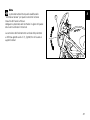
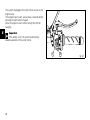
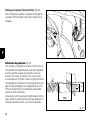
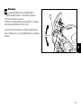
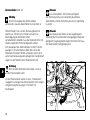
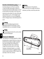
Variazione assetto motociclo (fig. 27-fig. 28-fig. 29)
L’assetto del motociclo rappresenta il risultato di prove
effettuate dai nostri tecnici nelle più svariate condizioni
di utilizzo.
La modifica di questo parametro rappresenta una
operazione molto delicata che, se eseguita con imperizia,
può risultare pericolosa.
Si consiglia, prima di modificare l’assetto standard,
di rilevare la quota (H, fig. 27) di riferimento.
Il pilota ha la possibilità di modificare l’assetto del
motociclo in funzione delle proprie esigenze di guida,
variando la posizione di lavoro dell’ammortizzatore.
Per modificare l’interasse degli snodi sferici (1)
è necessario allentare i controdadi (3).
H
fig. 27
Note
Fare attenzione al dado (3) inferiore che ha una
filettatura sinistrorsa.
2
1
Agire sul tirante (2) con una chiave aperta.
Eseguita la regolazione serrare i dadi (3) a 25 Nm.
Attenzione
La lunghezza del tirante (2), compresa tra gli assi degli
snodi (1), non deve superare i 272 mm.
1
3
3
2
32
fig. 28
La quota massima sfilamento dell’UNIBALL della testa (A)
snodata è 5 filetti pari a 7,5 mm (B).
I
B
A
fig. 29
33
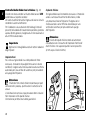
I
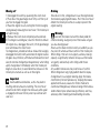
NORME D’USO
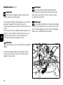
Precauzioni per il primo periodo d’uso del
motociclo (fig. 30)
Importante
Durante il periodo di rodaggio osservare
scrupolosamente il programma di manutenzione ed i
tagliandi consigliati nel libretto di garanzia. L’inosservanza
di tali norme esonera la Ducati Motor Holding S.p.A. da
qualsiasi responsabilità su eventuali danni al motore e sulla
sua durata.
Velocità di rotazione massima
Velocità di marcia o di rotazione da rispettare nel periodo di
rodaggio e nel normale uso:
1) Fino a 1000 km;
2) Da 1000 a 2500 km.
34
Fino a 1000 km
Durante i primi 1000 km di marcia fare attenzione al
contachilometri o contagiri, non si deve assolutamente
superare i:
6.000 min-1.
Nelle prime ore di marcia del motociclo è consigliabile
variare continuamente il carico ed il regime di giri del
motore, pur rimanendo sempre entro il limite indicato.
A questo scopo risultano adattissime le strade ricche di
curve e magari i tratti di strada collinari, dove il motore,
i freni e le sospensioni vengono sottoposti ad un rodaggio
efficace.
Per i primi 100 km agire con cautela sui freni evitando
brusche e prolungate frenate, questo per consentire un
corretto assestamento del materiale d’attrito delle
pastiglie sui dischi freno.
Per consentire un adattamento reciproco di tutte le parti
meccaniche in movimento ed in particolare per non
pregiudicare il duraturo funzionamento degli organi principali
del motore, si consiglia di non effettuare accelerazioni
troppo brusche e di non tenere a lungo il motore ad un
numero di giri elevato, particolarmente in salita.
Si consiglia inoltre di controllare spesso la catena, avendo
cura di lubrificarla, se necessario.
Da 1000 a 2500 km
Si può pretendere dal motore maggiori prestazioni, ma non
si deve mai superare i:
7.500 min-1.
0 ÷ 1000 Km
I
1000 ÷ 2500 Km
Attenendosi alle raccomandazioni si favorisce una maggiore
durata del motore, riducendo la necessità di revisioni o
di messe a punto.
fig. 30
35
I
Controlli prima dell’avviamento
Attenzione
La mancata esecuzione delle ispezioni prima della
partenza può causare danni al veicolo e procurare lesioni
gravi al conducente e al passeggero.
Prima di mettersi in viaggio controllare i seguenti punti:
Carburante nel serbatoio
Controllare il livello del carburante nel serbatoio.
Eventualmente fare rifornimento (pag. 41).
Livello olio nel motore
Controllare il livello nella coppa attraverso l’oblò d’ispezione.
Eventualmente rabboccare l’olio (pag. 60).
Liquido freni e frizione
Verificare sui rispettivi serbatoi il livello del liquido.
Liquido di raffreddamento
Controllare il livello del liquido nel serbatoio di espansione;
eventualmente rabboccare (pag. 47).
Condizione pneumatici
Controllare la pressione e lo stato di usura dei pneumatici
(pag. 58).
Funzionalità dei comandi
Azionare le leve e i pedali di comando freni, frizione,
acceleratore, cambio e controllare il funzionamento.
36
Luci e segnalazioni
Verificare l’integrità delle lampade d’illuminazione, di
segnalazione e il funzionamento del claxon. In caso di
lampade bruciate procedere alla sostituzione (pag. 53).
Serraggi a chiave
Controllare il bloccaggio del tappo serbatoio e della sella.
Cavalletto
Verificare la funzionalità e il corretto posizionamento del
cavalletto laterale (pag. 28).
Attenzione
In caso di anomalie rinunciare alla partenza e rivolgersi
ad un Concessionario o ad un’Officina Autorizzata.
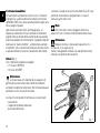
Attenzione
Prima di avviare il motore familiarizzare con i comandi
che si devono utilizzare durante la guida.
Non avviare mai il motore in un ambiente chiuso. I fumi
di scarico sono velenosi e possono provocare perdita di
conoscenza o addirittura la morte in tempi brevi.
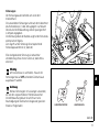
1) Spostare l'interruttore d'accensione sulla posizione ON
(fig. 31). Verificare che la spia verde N e quella rossa
sul cruscotto risultino accese.
2) Accertarsi che l’interruttore d’arresto (1, fig. 32) sia nella
posizione
(RUN), premere quindi il pulsante
avviamento (2).
Questo modello è provvisto di avviamento “servoassistito”.
Questa funzione permette l’avviamento servoassistito
del motore premendo e rilasciando immediatamente il
pulsante (2).
Alla pressione del pulsante (2) si ha l’avviamento automatico
del motore per un tempo massimo variabile in funzione della
temperatura del motore stesso.
Importante
La spia che indica la pressione dell’olio deve spegnersi
alcuni secondi dopo l’avvio del motore (pag. 11).
ON
N
K
Note
È possibile avviare il motore con il cavalletto aperto
ed il cambio in posizione di folle, oppure con la marcia
del cambio inserita, tenendo tirata la leva della frizione
(in questo caso il cavalletto deve essere chiuso).
ON
PU SH
O
FF
LO C
Attenzione
Il cavalletto laterale deve risultare in posizione di
riposo (orizzontale), altrimenti il sensore di sicurezza
inibisce l’avviamento.
P
O
Avviamento motore
I G NI
TI
fig. 31
37
I
I
A motore avviato il sistema inibisce il trascinamento del
motorino d’avviamento.
In caso di mancata accensione del motore è necessario
aspettare almeno 2 sec. prima di premere nuovamente
il pulsante di avviamento (2).
Lasciare che il motociclo si avvii spontaneamente,
senza azionare il comando dell’acceleratore.
Importante
In caso di batteria scarica il sistema inibisce
automaticamente il trascinamento del motorino
d’avviamento.
1
38
2
fig. 32
Importante
Non far funzionare il motore ad un elevato numero di
giri quando è freddo. Aspettare il riscaldamento dell’olio
e la sua circolazione in tutti i punti che necessitano di
lubrificazione.
I
Note
Il veicolo è dotato di uno starter automatico (Stepper
Motor),collocato sul gruppo farfallato.Tale dispositivo
permette il facile avviamento del motore, in condizioni di
temperatura ambiente diverse.
39
I
Avviamento e marcia del motociclo
1) Disinserire la frizione agendo sulla leva comando.
2) Con la punta del piede abbassare con decisione la leva
selezione marce in modo da innestare la prima marcia.
3) Accelerare il motore, agire sulla manopola comando
acceleratore, rilasciare contemporaneamente e lentamente
la leva della frizione; il veicolo inizierà a spostarsi.
4) Rilasciare completamente la leva frizione e accelerare.
5) Per passare alla marcia superiore chiudere l’acceleratore
per ridurre i giri del motore, disinserire la frizione, sollevare
la leva selezione marce e rilasciare la leva comando
frizione.
Il passaggio dalle marce superiori a quelle inferiori avviene
nel modo seguente: rilasciare l’acceleratore, disinserire
la frizione, accelerare un attimo il motore, per permettere
la sincronizzazione degli ingranaggi da innestare, scalare
quindi la marcia inferiore e rilasciare la frizione.
L’uso dei comandi deve avvenire con intelligenza e
tempestività: in salita quando il motociclo accenna a
diminuire la velocità passare immediatamente alla marcia
inferiore, si evitano cosi sollecitazioni anormali a tutta la
struttura del motociclo e non solo al motore.
Importante
Evitare accelerazioni brusche che possono provocare
ingolfamenti e strappi agli organi di trasmissione. Evitare di
tenere la frizione disinserita durante la marcia, ciò provoca
un riscaldamento ed un’usura anormale degli organi
d’attrito.
40
Frenata
Rallentare per tempo, scalare per utilizzare il freno motore
e poi frenare agendo su entrambi i freni. Prima che il
motociclo si arresti disinserire la frizione per evitare che
il motore si spenga improvvisamente.
Attenzione
L’utilizzo indipendente di uno dei due comandi freno
riduce l’efficacia frenante del motociclo.
Non azionare bruscamente e con forza eccessiva i
comandi dei freni; si può causare il bloccaggio delle ruote
con conseguente perdita di controllo del motociclo.
In caso di pioggia o quando si viaggia su superfici con poco
aderenza l’azione frenante del motociclo è notevolmente
ridotta. In queste situazioni azionare i comandi freni con
molta dolcezza ed attenzione.
Manovre improvvise possono causare la perdita del
controllo del motociclo.
Quando si affrontano lunghe discese con forte pendenza,
utilizzare la capacità frenante del motore scalando
di marcia, azionare i freni alternativamente e solo per
brevi tratti: un utilizzo continuo causa un riscaldamento
eccessivo del materiale d’attrito con una drastica riduzione
dell’efficacia frenante.
I pneumatici gonfiati ad una pressione inferiore a
quella prescritta diminuiscono l’efficienza della frenata e
compromettono la precisione di guida e la tenuta in curva.
Arresto del motociclo (fig. 33)
Ridurre la velocità, scalare di marcia e rilasciare la
manopola dell’acceleratore. Scalare fino ad inserire la
prima e successivamente la folle. Frenare ed arrestare il
motociclo. Spegnere il motore spostando la chiave nella
posizione OFF.
I
Importante
Non lasciare la chiave su ON a motore spento onde
evitare danni ai componenti elettrici.
fig. 33
Rifornimento carburante (fig. 34)
Durante il rifornimento non riempire eccessivamente il
serbatoio. Il livello del carburante deve rimanere al di sotto
del foro d’immissione nel pozzetto del tappo.
Max level
Attenzione
Usare un carburante con bassi contenuti di piombo,
con un numero di ottani, all’origine, di almeno 95.
Nel pozzetto del tappo non deve rimanere carburante.
fig. 34
41
I
Parcheggio (fig. 35)
Parcheggiare il motociclo fermo sul cavalletto laterale
(vedi pag. 28).
Ruotare il manubrio completamente a sinistra e portare
la chiave nella posizione LOCK per prevenire i furti.
Se si parcheggia in un garage o in altre strutture, fare
attenzione che sia ben ventilato e che il motociclo non
risulti vicino a fonti di calore.
In caso di necessità si può lasciare accesa la luce di
posizione, ruotando la chiave nella posizione P.
Importante
Non lasciare la chiave su P per tempi lunghi, la
batteria si potrebbe scaricare. Non lasciare mai la chiave
inserita quando il motociclo è incustodito.
Attenzione
L’impianto di scarico può essere caldo, anche dopo lo
spegnimento del motore; prestare molta attenzione a non
toccare con nessuna parte del corpo l’impianto di scarico e
a non parcheggiare il veicolo in prossimità di materiali
infiammabili (compreso legno, foglie, ecc.).
Attenzione
L’utilizzo di lucchetti o blocchi che impediscono
l’avanzamento del motociclo (es. bloccadisco,
bloccacorona, ecc.) è molto pericoloso e può
compromettere il funzionamento del motociclo e
la sicurezza di pilota e passeggero.
42
fig. 35
Accessori in dotazione
Sotto la sella, sono alloggiati:
un libretto uso e manutenzione;
un cavetto portacasco;
una busta attrezzi per le normali operazioni di
manutenzione e verifica.
I
1
Per accedere al vano è necessario rimuovere la sella
(pag. 27) e togliere il coperchio di protezione (1, fig. 36)
svitando la vite speciale di fissaggio con una moneta.
La busta attrezzi (fig. 37)
Contiene:
3) chiave a tubo esagonale per candele;
4) perno per chiave candela;
5) giravite doppio;
6) cavetto portacasco.
fig. 36
5
4
2
3
fig. 37
43
I
OPERAZIONI D’USO E MANUTENZIONE
PRINCIPALI
1
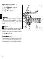
Rimozione della vestizione (fig. 38)
Per poter effettuare alcuni interventi di manutenzione o
riparazione è necessario rimuovere alcune parti della
vestizione del motociclo.
Attenzione
Il mancato o non corretto rimontaggio di una delle
parti rimosse può causarne l’improvviso distacco durante
la marcia con la conseguente perdita di controllo del
motociclo.
Rimozione cupolino
Svitare e rimuovere le due viti di fissaggio (1) all’archetto
reggifaro.
Note
Attenzione a non perdere i dadi di bloccaggio delle
viti (1) posti all’interno del cupolino.
Rimuovere il cupolino (2).
44
2
fig. 38
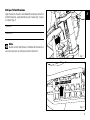
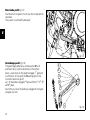
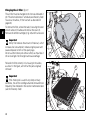
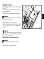
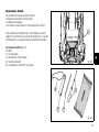
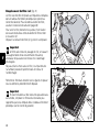
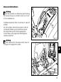
Sollevamento serbatoio carburante
I
Attenzione
Per evitare fuoriuscite di carburante dallo sfiato del
tappo carburante, il contenuto di carburante deve essere
minore di 5 litri.
Rimuovere la sella (pag. 27), sollevare il gancio (1, fig. 39).
Sollevare il serbatoio e sganciare l’astina (2, fig. 40)
di servizio dalla propria sede, sotto alla sella.
Appoggiare il serbatoio sull’astina di servizio.
Per rimontarlo eseguire le operazioni descritte in ordine
inverso
1
Attenzione
Quando si abbassa il serbatoio fare attenzione che
le tubazioni siano correttamente posizionate in modo da
evitare che si schiaccino.
fig. 39
2
fig. 40
45
I
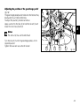
Sostituzione del filtro aria (fig. 41)
Il filtro aria deve essere sostituito agli intervalli prescritti
nella tabella di manutenzione periodica (vedi Libretto
Garanzia). Per accedere alla scatola filtro sollevare il
serbatoio carburante (pag. 45).
Per rimuovere il filtro, sganciare le linguette (1) di fissaggio
del coperchio su entrambi i lati della scatola filtro e
rimuovere il coperchio (2).
Rimuovere la cartuccia filtro (3, fig. 42) e sostituirla.
Importante
Un filtro sporco riduce l’entrata dell’aria aumentando
il consumo di carburante, riducendo la potenza del motore
e provocando incrostazioni sulle candele.
Non usare il motociclo senza filtro; le impurità presenti
nell’aria potrebbero entrare nel motore danneggiandolo.
Reinstallare correttamente il filtro, come indicato in figura,
nella sede della scatola filtro e rimontare tutti gli elementi
rimossi.
2
1
fig. 41
3
Importante
In caso d’impiego su strade polverose o umide
provvedere alla sostituzione più frequentemente di quanto
prescritto nella tabella di manutenzione periodica
(vedi Libretto Garanzia).
fig. 42
46
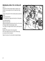
Controllo livello liquido di raffreddamento (fig. 43)
Controllare il livello del liquido di raffreddamento contenuto
nel serbatoio d’espansione, sul lato destro del motociclo;
deve risultare compreso tra i riferimenti di MAX e di MIN
del serbatoio.
Se il livello risulta basso, è necessario provvedere al
rabbocco.
Svitare il tappo di carico (1) e aggiungere una miscela
d’acqua e antigelo SHELL Advance Coolant o Glycoshell
(35÷40% del volume) fino a raggiungere il livello MAX.
Riavvitare il tappo (1).
Se si utilizza questo tipo di miscela si ottengono le migliori
condizioni d’esercizio (corrispondenti a -20 °C/-4 °F inizio
congelamento liquido).
I
1
fig. 43
Capacità del circuito di raffreddamento: 2,7 dm3 (litri).
Attenzione
Questa operazione deve essere eseguita a motore
freddo e con il motociclo perfettamente in piano.
47
I
Controllo livello fluido freni e frizione (fig. 44)
Il livello non deve scendere al di sotto della tacca di MIN
evidenziata sui rispettivi serbatoi.
Un livello insufficiente facilita l’ingresso di aria nel circuito
rendendo il sistema inefficiente.
Per il rabbocco o la sostituzione del fluido agli intervalli
prescritti nella tabella di manutenzione periodica, riportata
sopra al libretto garanzia, rivolgersi ad un Concessionario o
ad un’Officina Autorizzata.
Importante
Ogni 4 anni è consigliabile sostituire tutte le tubazioni
degli impianti.
Impianto frizione
Se il gioco della leva di comando è eccessivo e il motociclo
salta o si arresta all’inserimento della marcia, indica
una presenza d’aria nell’impianto. Rivolgersi ad un
Concessionario o ad un’Officina Autorizzata per una
verifica del sistema e per provvedere allo spurgo
dell’impianto.
Attenzione
Il livello del liquido frizione tende ad aumentare
nel serbatoio con il consumo del materiale d’attrito dei
dischi frizione: non superare quindi il valore prescritto
(3 mm sopra il livello minimo).
Impianto freni
Se si rileva un gioco della leva o del pedale del freno
eccessivo, nonostante le pastiglie freno siano in buone
condizioni, rivolgersi ad un concessionario o ad una officina
autorizzata per una verifica del sistema e per provvedere
allo spurgo dell’impianto.
Attenzione
Il fluido dei freni e della frizione è dannoso per parti
verniciate ed in plastica, quindi evitare il contatto con le
stesse.
L’olio idraulico è corrosivo e può provocare danni e lesioni.
Non mescolare olii di qualità diverse.
Controllare la perfetta tenuta delle guarnizioni.
fig. 44
48
Verifica usura pastiglie freno (fig. 45)
MIN
I
Freno anteriore
Per facilitare il controllo delle pastiglie dei freni, senza
doverle rimuovere dalla pinza, ogni pastiglia riporta un
indicatore di consumo. Sulla pastiglia in buone condizioni
debbono essere ben visibili le scanalature praticate sul
materiale d’attrito.
Freno posteriore
Su ogni pastiglia lo spessore del materiale d’attrito deve
essere almeno 1 mm.
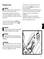
Regolazione del cavo comando acceleratore
La manopola di comando acceleratore in tutte le posizioni
di sterzata deve avere una corsa a vuoto, misurata sulla
periferia del bordino della manopola, di 2÷4 mm.
Se necessario regolarla agendo sull’apposito registro
(1, fig. 46) situato in corrispondenza del comando stesso.
fig. 45
1
1 mm
➤
➤
Importante
Per la sostituzione delle pastiglie freno rivolgersi ad
un Concessionario o ad un’Officina Autorizzata.
fig. 46
49
I
Lubrificazione delle articolazioni (fig. 47)
Periodicamente è necessario controllare le condizioni
delle guaine esterne dei cavi di comando acceleratore.
Non devono presentare schiacciamenti o screpolature nel
rivestimento plastico esterno. Verificare il funzionamento
scorrevole del cavo interno agendo sul comando: se si
manifestano attriti o impuntamenti farlo sostituire da un
concessionario o una officina autorizzata.
Per evitare questi inconvenienti lubrificare periodicamente
l’estremità dei cavi di ogni trasmissione flessibile con
grasso SHELL Advance Grease o Retinax LX2.
Nel caso della trasmissione acceleratore si consiglia di
aprire il comando, svitando le due viti di fissaggio (1),
quindi ingrassare l’estremità del cavo e la carrucola.
Attenzione
Richiudere con molta attenzione il comando
inserendo il cavo nella carrucola.
Rimontare il coperchio e serrare le viti (1) alla coppia di
1,8 Nm.
Per garantire un funzionamento ottimale dell’articolazione
del cavalletto laterale è necessario, dopo aver eliminato
ogni traccia di sporco, lubrificare con grasso SHELL
Alvania R3 tutti i punti soggetti ad attrito.
50
1
fig. 47
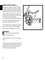
Carica della batteria (fig. 48)
Per ricaricare la batteria è consigliabile rimuoverla dal
motociclo.
Staccare per primo, il terminale negativo (-) nero, poi quello
positivo (+) rosso.
Sganciare il fermo (1) e rimuovere la batteria.
-
1
I
+
Attenzione
La batteria produce gas esplosivi: tenerla lontano da
fonti di calore.
Caricare la batteria in un luogo ben ventilato.
Collegare i conduttori del caricabatterie ai rispettivi
terminali: rosso al positivo (+), nero al negativo (-).
Importante
Collegare la batteria al caricabatteria prima di attivarlo,
per evitare la formazione di scintille in corrispondenza dei
terminali della batteria, che potrebbero incendiare i gas
contenuti nelle celle.
Collegare sempre per primo il terminale positivo
(rosso).
fig. 48
Attenzione
Tenere la batteria lontano dalla portata dei bambini.
Caricare la batteria a 1 A per 5÷10 ore.
51
I
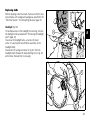
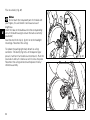
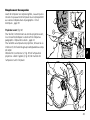
Controllo tensione catena trasmissione (fig. 49)
Spostare lentamente il motociclo per trovare la posizione
in cui il ramo superiore della catena risulta più tesa.
Posizionare il motociclo sul cavalletto laterale. Spingere la
catena con un dito verso l'alto in corrispondenza della
mezzeria del forcellone (vedi targhetta adesiva). Il ramo
inferiore della catena deve poter compiere una escursione
di circa 30÷32 mm.
In caso contrario rivolgersi ad un Concessionario o ad
un’Officina Autorizzata per eseguire il tensionamento della
catena.
Importante
L’utilizzo di lubrificanti non specifici potrebbe
danneggiare la catena, la corona e il pignone motore.
Attenzione
Il corretto serraggio delle viti di bloccaggio del mozzo
eccentrico è fondamentale per la sicurezza del pilota.
Importante
Una catena non correttamente tensionata è causa di
rapida usura degli organi di trasmissione.
Lubrificazione della catena trasmissione
Questo tipo di catena è provvista di anelli o-ring per
proteggere gli elementi di scorrimento dagli agenti esterni
e mantenere più a lungo la lubrificazione.
Per non danneggiare queste guarnizioni durante la pulizia,
utilizzare solventi specifici e non effettuare un lavaggio
troppo violento con idropulitrici a vapore. Asciugare la
catena con aria compressa o con materiale assorbente e
lubrificatela, in ogni suo elemento, con SHELL Advance
Chain o Advance Teflon Chain.
52
=
30 ÷ 32 mm
=
fig. 49
Sostituzione delle lampadine
Prima di procedere alla sostituzione di una lampadina
bruciata accertarsi che quella di ricambio abbia i valori di
tensione e potenza uguali a quelli specificati nel paragrafo
“Impianto Elettrico” a pag. 70.
I
Proiettore anteriore (fig. 50)
Per agevolare la manutenzione al proiettore anteriore è
consigliabile rimuovere il cupolino come indicato al
parafrago “Rimozione cupolino” (pag. 44).
Per accedere alle lampadine del proiettore svitare la vite
inferiore (1) che fissa il gruppo cornice/parabola al corpo
lampada.
Staccare il connettore (2, fig. 51) dalla lampadina del
proiettore. Sganciare la molletta (3, fig. 51) di tenuta
della lampada e rimuoverla dal supporto.
1
fig. 50
3
2
fig. 51
53
I
Sostituire la lampada (4, fig. 52).
Note
La parte trasparente della lampadina nuova non deve
essere toccata con le mani, ne provocherebbe
l’annerimento riducendone la luminosità.
Inserire le linguette della base lampadina, nelle sedi
corrispondenti per ottenere l’esatto orientamento;
agganciare l’estremità della molletta (3, fig. 51) ai supporti
del corpo proiettore. Ricollegare i cavi.
4
Per sostituire la lampadina della luce di posizione, staccare
il relativo connettore. La lampadina (5, fig. 53) ha un
innesto a baionetta, per estrarla occorre premere e ruotarla
in senso antiorario. Sostituire la lampadina e inserirla
premendo e ruotandola in senso orario fino allo scatto nella
sede. Rimontare il connettore e fissare il complessivo
cornice/parabola.
fig. 52
5
fig. 53
54
Indicatori di direzione (fig. 54)
Svitare la vite (1) e separare la coppetta (2) dal supporto
indicatore.
La lampadina ha un innesto a baionetta, per estrarla
occorre premere e ruotarla in senso antiorario. Sostituire la
lampadina e reinserirla premendo e ruotando in senso
orario fino allo scatto nella sede. Rimontare la coppetta
inserendo il dentino (A) nell’apposita fessura del supporto
indicatore.
Riavvitare la vite (1).
I
A
2
1
fig. 54
Luce arresto (fig. 55)
Per la sostituzione della lampada luce arresto e
posizione è necessario svitare le due viti (1) che fissano
il trasparente (2) e rimuoverlo. La lampadina ha un innesto
a baionetta, per estrarla occorre premere e ruotarla in
senso antiorario. Sostituire la lampadina e reinserirla
premendo e ruotando in senso orario fino allo scatto
nella sede. Rimontare il trasparente.
1
2
fig. 55
55
I
Luce targa (fig. 56)
Per accedere alla lampadina della luce targa (3), sfilare
il portalampada dall’interno, quindi sfilare la lampada e
sostituirla.
3
fig. 56
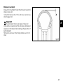
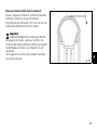
Orientamento del proiettore (fig. 57)
Controllare se il proiettore è correttamente orientato
mettendo il motociclo, con i pneumatici gonfiati alla giusta
pressione e con una persona seduta in sella, perfettamente
perpendicolare con il suo asse longitudinale di fronte ad una
parete o ad uno schermo, distante da esso 10 metri.
Tracciare una linea orizzontale corrispondente all’altezza
del centro del proiettore e una verticale in linea con l’asse
longitudinale del motociclo.
Effettuare il controllo possibilmente nella penombra.
Accendere la luce anabbagliante:
il limite superiore di demarcazione tra la zona oscura e la
zona illuminata deve risultare ad una altezza non superiore
a 9/10 dell’altezza da terra del centro del proiettore.
56
9 x
10
x
10 m
fig. 57
Note
La procedura descritta è quella stabilita dalla
“Normativa Italiana” per quanto concerne l’altezza
massima del fascio luminoso.
Adeguare la procedura alle normative in vigore nel paese
dove viene utilizzato il motociclo.
I
1
La correzione dell’orientamento verticale del proiettore
si effettua agendo sulle viti (1, fig. 58) che lo fissano ai
supporti laterali.
fig. 58
57
I
Pneumatici
Pressione anteriore:
2,1 bar - 2,3 Kg/cm2
Pressione posteriore:
2,2 bar - 2,4 Kg/cm2
La pressione dei pneumatici è soggetta a variazioni dovute
alla temperatura esterna e all’altitudine; controllarla e
adeguarla ogni volta che si viaggia in zone con ampie
escursioni termiche o in alta quota.
Importante
La pressione dei pneumatici, deve essere controllata
e regolata a “gomma fredda”.
Per salvaguardare la rotondità del cerchio anteriore, se si
percorrono strade molto sconnesse, aumentare la
pressione nel pneumatico di 0,2÷0,3 bar.
Riparazione o sostituzione pneumatici
I pneumatici senza camera d’aria in presenza di forature di
lieve entità, impiegano molto tempo a sgonfiarsi in quanto
hanno un certo grado d’autotenuta. Se un pneumatico
risulta leggermente sgonfio controllare attentamente che
non ci siano perdite.
Attenzione
In caso di foratura sostituire il pneumatico.
Sostituire i pneumatici utilizzando la marca e il tipo di primo
equipaggiamento.
Assicurarsi di aver avvitato i cappucci di protezione delle
valvole per evitare perdite di pressione durante la marcia.
Non usate mai un pneumatico con camera d’aria;
la mancata osservanza di questa norma può causare
lo scoppio improvviso del pneumatico, con gravi
conseguenze per pilota e passeggero.
Dopo la sostituzione di un pneumatico è necessario
provvedere all’equilibratura della ruota.
Importante
Non rimuovere o spostare i contrappesi per
l’equilibratura delle ruote.
Note
Per la sostituzione dei pneumatici rivolgersi ad un
Concessionario o ad un’Officina Autorizzata per avere la
garanzia sul corretto smontaggio e rimontaggio delle ruote.
58
Spessore minimo del battistrada
Misurare lo spessore minimo (S, fig. 59) del battistrada nel
punto di massimo consumo:
non deve essere inferiore a 2 mm e comunque non
inferiore a quanto prescritto dalla legislazione locale.
I
Importante
Controllare periodicamente i pneumatici per
individuare eventuali crepe o tagli, soprattutto nelle pareti
laterali, rigonfiamenti o macchie estese ed evidenti che
indicano danni interni; sostituirli in caso di danno grave.
Togliere dal battistrada sassolini o altri corpi estranei
rimasti incastrati nella scolpitura della gomma.
fig. 59
59
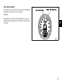
Controllo livello olio motore (fig. 60)
Il livello dell’olio nel motore è visibile attraverso l’oblò di
ispezione (1) posto sul lato destro della coppa dell’olio.
Controllare il livello con il motociclo in posizione
perfettamente verticale e con motore freddo.
Il livello deve mantenersi tra le tacche in corrispondenza
dell’oblò stesso. Se il livello risulta scarso è necessario
procedere al rabbocco con l’olio motore SHELL Advance
Ultra 4. Rimuovere il tappo di carico (2) e aggiungere olio
fino a raggiungere il livello stabilito. Rimontare il tappo.
1
2
Importante
Per la sostituzione dell’olio motore e dei filtri olio agli
intervalli prescritti nella tabella di manutenzione periodica
(vedi Libretto Garanzia), rivolgersi ad un Concessionario o
ad un’Officina Autorizzata.
Viscosità
SAE 10W-40
Le altre viscosità indicate in tabella possono essere usate
se la temperatura media della zona d’uso del motociclo si
trova nei limiti della gamma indicata.
fig. 60
10W
Multigrade Unigrade
I
20W
20
30
40
20W–40 20W–50
15W–40 15W–50
10W–40
10W–30
–10
60
0
10
20
30
40 C
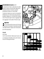
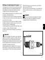
Pulizia e sostituzione candele (fig. 61)
Le candele costituiscono un elemento importante del
motore e sono da controllare periodicamente.
Questa operazione è relativamente facile e permette di
verificare il buono stato di funzionamento del motore.
Sfilare le bobine dalle candele e rimuoverle dalla testa
utilizzando la chiave a corredo.
Verificare la colorazione dell’isolante ceramico
dell’elettrodo centrale: una colorazione uniforme marrone
chiaro indica un buon funzionamento del motore.
Nel caso di colorazioni diverse o incrostazioni scure,
sostituire la candela e riferire quanto riscontrato a un
Concessionario o ad un’Officina Autorizzata.
Controllare anche l’usura dell’elettrodo centrale; se risulta
consumato o vetroso, sostituire la candela.
Controllare la distanza fra gli elettrodi, deve essere di:
0,6÷0,7 mm.
Rimontare la candela sulla testa avvitandola fino a fine
filetto. Serrare alla coppia di 20 Nm.
Se non si dispone di una chiave dinamometrica, dopo
un serraggio a mano, effettuare un’ulteriore rotazione di
1/2 giro con la chiave in dotazione.
Importante
Non usare candele con un grado termico inadeguato
o con filetto di lunghezza diversa.
La candela deve essere serrata correttamente.
Importante
In caso di regolazione fare attenzione a piegare
l’elettrodo laterale. Una distanza maggiore o minore,
oltre a diminuire le prestazioni, può causare difficoltà di
avviamento o problemi di funzionamento al minimo.
Pulire accuratamente l’elettrodo e l’isolante con uno
spazzolino metallico e verificare lo stato della guarnizione.
Pulire con cura la sede sulla testa e fare attenzione a non
far cadere corpi estranei all’interno della camera di scoppio.
fig. 61
61
I
I
Pulizia generale
Per mantenere nel tempo la brillantezza originale delle
superfici metalliche e di quelle verniciate, il motociclo deve
essere lavato e pulito periodicamente a seconda del
servizio e dello stato delle strade che si percorrono.
Utilizzare a tal fine prodotti specifici, possibilmente
biodegradabili, evitando detergenti o solventi troppo
aggressivi.
Importante
Non lavare il motociclo immediatamente dopo l’uso
per evitare la formazione di aloni prodotti dall’evaporazione
dell’acqua sulle superfici ancora calde.
Non indirizzare verso il motociclo getti di acqua calda o ad
alta pressione. L’uso di idropulitrici potrebbe comportare
grippaggi o gravi anomalie a forcelle, perni ruota, impianto
elettrico, guarnizioni di tenuta della forcella, prese d’aria e
silenziatori di scarico, con conseguente perdita dei requisiti
di sicurezza del mezzo.
Se alcune parti del motore risultano particolarmente
sporche o unte, utilizzare uno sgrassante per la pulizia
evitando che questo vada a contatto con gli organi
della trasmissione (catena, pignone, corona, ecc.).
Sciacquare il motociclo con acqua tiepida e asciugare
tutte le superfici con una pelle scamosciata.
62
Attenzione
I freni talvolta possono non rispondere dopo il
lavaggio del motociclo. Non ingrassare o lubrificare i dischi
freno, si perderebbe l’efficacia frenante del motociclo.
Pulite i dischi con un solvente non grasso.
Lunga inattività
Se il motociclo non viene usato per un lungo periodo
è consigliabile eseguire le seguenti operazioni:
pulizia generale;
vuotare il serbatoio carburante;
introdurre dalle sedi delle candele un po’ d’olio motore nei
cilindri e far compiere, a mano, qualche giro al motore per
distribuire un velo protettivo sulle pareti interne;
utilizzare il cavalletto di servizio per sostenere il motociclo;
scollegare e rimuovere la batteria. Qualora il motociclo sia
rimasto inattivo per un periodo superiore ad un mese,
controllare ed eventualmente ricaricare la batteria.
Ricoprire il motociclo con un telo coprimoto che non
danneggia la vernice e non trattiene la condensa.
Il telo coprimoto è disponibile presso Ducati Performance.
Avvertenze importanti
In alcune nazioni (Francia, Germania, Gran Bretagna,
Svizzera, ecc.) la legislazione locale richiede il rispetto di
norme anti-inquinamento ed anti-rumore.
Effettuare le eventuali verifiche periodiche previste e
sostituire quanto necessario con ricambi originali Ducati
specifici e conformi alle norme dei vari paesi.
63
I
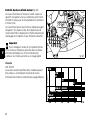
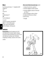
CARATTERISTICHE TECNICHE
Pesi
Pesi
A secco:
177 kg.
A pieno carico:
390 kg.
Attenzione
Il mancato rispetto dei limiti di carico potrebbe
influenzare negativamente la maneggevolezza e la resa del
vostro motociclo e potrebbe causarne la perdita di controllo.
Ingombri (mm) (fig. 62)
128
985
1060
1222
496
806
885
790
355
I
1440
2121
64
fig. 62
Rifornimenti
Tipo
dm3 (litri)
Serbatoio carburante, compresa una riserva
di 3,5 dm3 (litri)
Benzina verde con un numerodi ottani
all’origine di almeno 95
15
Circuito di lubrificazione
SHELL Advance Ultra 4
3,4
Circuito freni ant./post. e frizione
SHELL Advance Brake DOT 4
—
Protettivo per contatti elettrici
SHELL Advance Contact Cleaner
—
Forcella anteriore
SHELL Advance Fork 7.5 o Donax TA
0,492 (per stelo)
Circuito di raffreddamento
Liquido antigelo SHELL Advance Coolant o
GLYCO SHELL 35÷40 % + acqua
2,7
I
Importante
Non è ammesso l’uso di additivi nel carburante o nei lubrificanti.
65
I
Motore
Bicilindrico a 4 tempi a “L” longitudinale di 90°.
Alesaggio mm:
100.
Corsa mm:
63,5.
Cilindrata totale cm3:
998.
Rapporto di compressione:
11,4±0,5:1.
Potenza max. all’albero (95/1/CE):
88,8 kW - 119 CV a 9.250 giri/min.
Coppia massima all'albero (95/1/CE):
96,9 Nm (9,9 Kgm) a 7.500 giri/min.
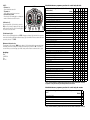
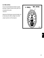
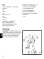
Schema distribuzione desmodromica (fig. 63)
1) Bilanciere di apertura (o superiore);
2) registro bilanciere superiore;
3) registro bilanciere di chiusura (o inferiore);
4) molla richiamo bilanciere inferiore;
5) bilanciere di chiusura (o inferiore);
6) albero distribuzione;
7) valvola.
Distribuzione
Desmodromica a quattro valvole per cilindro comandate
da otto bilancieri (quattro di apertura e quattro di chiusura)
e da due alberi distribuzione in testa. È comandata
dall’albero motore mediante ingranaggi cilindrici, pulegge
e cinghie dentate.
6
1
2
3
7
66
5
4
fig. 63
Prestazioni
La velocità massima nelle singole marce è ottenibile
solo osservando scrupolosamente le norme di rodaggio
prescritte ed eseguendo periodicamente le manutenzioni
stabilite.
Importante
L’inosservanza di tali norme esonera la Ducati Motor
Holding S.p.A. da qualsiasi responsabilità su eventuali
danni al motore e sulla sua durata.
Candele d’accensione
Marca: CHAMPION
Tipo: RA 4 HC
Alimentazione
Iniezione elettronica indiretta MARELLI.
Diametro corpo farfallato:
50 mm
Iniettori per cilindro: 1
Fori per iniettori: 1
Alimentazione benzina: 95-98 RON.
Freni
Anteriore
Tipo:
a disco forato in acciaio.
n° 2 dischi.
Materiale pista frenante:
acciaio.
Materiale campana:
alluminio.
Diametro disco: 320 mm.
Comando idraulico mediante leva sul lato destro del
manubrio.
Superficie frenante, cm2: 52,52.
Pinze freno ad attacco radiale.
Marca e tipo: BREMBO P4.34B.
Materiale attrito: Toshciba TT2172.
Tipo pompa: PR18/19.
I
Posteriore
Tipo:
a disco fisso forato, in acciaio.
Diametro disco: 245 mm.
Comando idraulico mediante pedale sul lato destro.
Superficie frenante: 25 cm2.
Pinza freno: Ø cilindro 32 mm.
Marca e tipo: BREMBO P32F.
Materiale attrito: FERIT I/D 450 FF.
Tipo pompa: PS 11B.
Attenzione
Il liquido impiegato nell’impianto frenante è corrosivo.
Nel caso di un accidentale contatto con gli occhi o la pelle
lavare abbondantemente con acqua corrente la parte
interessata.
67
I
Trasmissione
Frizione:
multidisco a secco;
comandata mediante leva sul lato sinistro del manubrio.
Trasmissione fra motore ed albero primario del cambio ad
ingranaggi a denti diritti.
Rapporto:
32/59.
Cambio a:
a 6 rapporti;
con ingranaggi sempre in presa, pedale comando a
sinistra.
Rapporto pignone/corona:
15/43.
Rapporti totali:
1a 15/37.
2a 17/30.
3a 20/27.
4a 22/24.
5a 24/23.
6a 28/24.
Trasmissione fra il cambio e la ruota posteriore mediante
una catena:
Marca: DID
Tipo: 525 HV
Dimensioni: 5/8 x 5/16”
N° maglie: 106.
68
Importante
I rapporti indicati sono quelli omologati e non
possono essere cambiati.
Se si desidera adattare il motociclo a percorsi speciali o
gare, la Ducati Motor Holding S.p.A. è a disposizione per
indicare dei rapporti diversi da quelli di serie; rivolgersi ad
un Concessionario o un’Officina Autorizzata.
Attenzione
Dovendo sostituire la corona posteriore, rivolgersi
ad un Concessionario o un’Officina Autorizzata.
Una sostituzione imperfetta di questo componente può
compromettere gravemente la tua sicurezza e quella del
passeggero e provocare danni irreparabili al motociclo.
Telaio
Tubolare a traliccio a gabbia superiore in tubi d’acciaio ad
altoresistenziale.
Angolo di sterzata (per lato): 27°
Avancorsa mm: 96
Inclinazione cannotto: 24°.
Ruote
Cerchi in lega leggera a cinque razze a “Y”.
Corsa sull’asse steli:
130 mm.
Anteriore
Dimensioni: MT3.50x17".
Posteriore
Ad azionamento progressivo ottenuto con l’interposizione
di un bilanciere tra telaio e fulcro superiore
dell’ammortizzatore. L’ammortizzatore regolabile in
estensione, compressione e nel precarico della molla.
È infulcrato nella parte inferiore ad un forcellone oscillante
in alluminio.
Il forcellone ruota intorno al perno fulcro passante per il
motore. Questo sistema conferisce al mezzo eccezionali
doti di stabilità.
Corsa ammortizzatore:
65 mm.
Escursione ruota posteriore:
148 mm.
Posteriore
Dimensioni: MT5.50x17".
Entrambe le ruote sono a perno sfilabile.
Pneumatici
Anteriore
Radiale tipo “tubeless”.
Dimensione: 120/70-ZR17.
Posteriore
Radiale tipo “tubeless”.
Dimensione: 180/55-ZR17.
Sospensioni
I
Note
Non effettuare interventi sul motociclo che possono
modificare le caratteristiche tecniche in base alle quali è
stata ottenuta l’omologazione.
Anteriore
A forcella oleodinamica a steli rovesciati.
La forcella è dotata di sistema di regolazione esterna
del freno idraulico in estensione, compressione e del
precarico delle molle interne agli steli.
Diametro tubi portanti mm:
43.
69
I
Impianto di scarico
Catalizzato in conformità alle normative antinquinamento
Euro 2.
Versione U.S.A.: non catalizzata.
Colori disponibili
Rosso cod. PPG 473101, trasparente cod. PPG 228880,
con banda bianca.
Telaio rosso e ruote nere.
Nero cod. PPG 248514, trasparente cod. PPG 228880,
con banda grigia.
Telaio nero opaco e ruote nere.
Perla cod. PPG*0040, fondo cod. PPG 490019,
trasparente cod. PPG 228880, con banda rossa.
Telaio rosso e ruote bianche.
Impianto elettrico
Formato dai seguenti particolari principali:
Proiettore anteriore:
lampada tipo: H4 (12 V-55/60 W).
luce di posizione:
lampada tipo: T4W (12 V-4 W).
Comandi elettrici sui semimanubri:
Indicatori direzione:
lampade tipo: R10W (12 V-10 W).
Avvisatore acustico.
Interruttori luci arresto.
Batteria, 12 V-10 Ah.
Alternatore 12 V-520 W.
Regolatore elettronico, protetto con fusibile da 40 A
posto a lato della batteria.
Motorino avviamento, 12 V-0,7 kW.
Fanale posteriore e segnalazione arresto:
lampada tipo: P21/5W (12 V-5/21 W).
Illuminazione targa:
lampada tipo: W5W (12 V-5 W).
Note
Per la sostituzione delle lampadine vedi al paragrafo
“Sostituzione delle lampadine” alla pag. 53.
70
Fusibili
La scatola porta fusibili è posizionata sotto il serbatoio
carburante.
I fusibili utilizzati sono accessibili rimuovendo il coperchio
di protezione (1, fig. 64) sulla cui superficie è riportato
l’ordine di montaggio e l’amperaggio.
Il fusibile posto vicino alla batteria protegge il regolatore
elettronico.
Per accedere al fusibile è necessario rimuovere il
cappuccio di protezione (2, fig. 64).
I
2
1
Un fusibile bruciato si riconosce dall’interruzione del
filamento conduttore interno (3, fig. 65).
fig. 64
Importante
Per evitare possibili corto circuiti eseguire la
sostituzione del fusibile con chiave d’accensione in
posizione OFF.
Attenzione
Non usare mai un fusibile con caratteristiche diverse
da quelle prescritte. La mancata osservanza di questa
norma potrebbe provocare danni al sistema elettrico o
addirittura incendi.
3
3
INTEGRO
BRUCIATO
fig. 65
71
I
Legenda schema impianto elettrico/iniezione
1) Commutatore destro.
2) Antenna Transponder.
3) Commutatore chiave.
4) Relè Ventole.
5) Relè Principale.
6) Scatola fusibili.
7) Ventola Sx.
8) Ventola Dx.
9) Motorino avviamento.
10)Teleruttore avviamento.
11)Diodo”Antirimbalzo”.
12)Batteria
13)Fusibile Master.
14)Regolatore.
15)Alternatore.
16)Indicatore direzione posteriore destro.
17)Fanale posteriore.
18)Illuminazione targa.
19)Indicatore direzione posteriore sinistro.
20)Serbatoio carburante.
21)Relè iniezione.
22)Connessione autodiagnosi.
23)Sensore velocità.
24)Interruttore stampella laterale.
25)Sonda Lambda.
26)Bobina cilindro orizzontale.
27)Bobina cilindro verticale.
28)ICandela cilindro orizzontale.
29)Candela cilindro verticale.
72
30)Iniettore cil. orizzontale.
31)Iniettore cil. verticale.
32)Potenziometro farfalla.
33)Sensore giri/fase.
34)Sensore temperatura acqua centralina.
35)Stepper Motor.
36)Centralina 5AM.
37)Interruttore folle.
38)Interruttore pressione olio.
39)Interruttore stop posteriore.
40)Interruttore stop anteriore.
41)Interruttore frizione.
42)Commutatore SX.
43)Sensore temperatura acqua strumento.
44)Sensore temperatura/pressione aria.
45)Strumentazione cruscotto.
46)Freccia anteriore SX.
47)Claxon.
48)Proiettore.
49)Freccia anteriore DX.
Legenda colore cavi
B Blu
W Bianco
V Viola
Bk Nero
Y Giallo
R Rosso
Lb Azzurro
G Verde
Bn Marrone
O Arancio
P Rosa
Gr Grigio
Legenda scatola fusibili (5)
Pos.
Utilizzatori
1
N.C
2
KEY-ON CENTRALINA, CRUSCOTTO,
TELERUTTORE LAMBDA E STOP
10 A
3
LUCE POSIZIONE,
LUCE ABBAGLIANTE E
ANABBAGLIANTE
15 A
4
PASSING, CLAXON E
LUCE STOP
15 A
5
INIEZIONE
(POMPA INIETTORE BOBINA)
20 A
6
CENTRALINA
CONTROLLO MOTORE
5A
7
CRUSCOTTO
5A
I
Val.
Note
Lo schema dell’impianto elettrico si trova alla fine
del libretto.
73
I
PROMEMORIA MANUTENZIONI PERIODICHE
Km
1000
10000
20000
30000
40000
50000
74
Nome
Ducati Service
Chilometraggio
Data
Use and maintenance manual
E
DUCATIMONSTERS4Rs
1
E
2
First of all, we bid you welcome to the world of Ducati
enthusiasts and congratulate you on your excellent choice
of motorcycle. We are sure that you will use your Ducati
for longer journeys as well as short daily trips, but however
you use your motorcycle, Ducati Motor Holding s.p.a
wishes you an enjoyable ride.
As part of our continuous effort to improve our service, we
advise you to strictly follow the indications given in this
manual, especially as regards running-in. In this way, you
can be sure your Ducati motorcycle will continue to be a
pleasure to ride.
For repairs or advice, please contact one of our authorized
service centres.
We also provide an information service for all Ducati
owners and enthusiasts for any advice and suggestions
you might need.
Notes
Ducati Motor Holding S.p.A. cannot accept any liability
for errors that may have occurred in the preparation of this
manual. All information in the manual is valid at the time of
going to print. Ducati Motor Holding S.p.A. reserves the
right to make any modifications required due to the ongoing
development of their products.
Enjoy the ride!
Warning
This manual is an integral part of the product and,
if ownership is transferred to a third party, must always be
passed to the new owner.
For safety and reliability, to avoid invalidating the warranty
and to maintain the value of your motorcycle, use only
original Ducati spare parts.
3
E
TABLE OF CONTENTS
E
Right-hand handlebar switch 20
Throttle twistgrip 20
Front brake lever 21
Rear brake pedal 22
Gearchange pedal 22
Adjusting the position of the gearchange pedal 23
Adjusting the position of the rear brake pedal 24
General indications 6
Warranty 6
Symbols 6
Useful road safety information 7
Riding with a full load 8
Identification data 9
Main components and devices
Position on motorcycle 25
Fuel tank filler cap 26
Seat and helmet holder lock 27
Sidestand 28
Shock absorber adjusters 29
Front fork adjusters 30
Adjusting the rear ride height 32
Controls 10
Position of the motorcycle controls 10
Instrument panel 11
The immobilizer system 14
Keys 14
Code card 15
Procedure to override the immobilizer using the throttle
twistgrip 16
Duplicate keys 17
Ignition switch and steering lock 18
Left-hand handlebar switch 19
Clutch lever 19
Riding the motorcycle 34
Running-in precautions 34
Pre-ride checks 36
Starting the engine 37
Moving off 40
Braking 40
Stopping the motorcycle 41
Refuelling 41
Parking 42
Toolkit and accessories 43
4
25
Main Use and Maintenance Operations
Removing the fairing panels 44
Lifting the fuel tank 45
Changing the air filter 46
Checking coolant level 47
Checking the brake and clutch fluid levels 48
Checking the brake pads for wear 49
Adjusting the throttle cable 49
Lubricating cables and joints 50
Charging the battery 51
Checking the chain tension 52
Lubrication of the drive chain 52
Replacing bulbs 53
Headlight aim 56
Tyres 58
Checking the engine oil level 60
Cleaning and renewing the spark plugs 61
General cleaning 62
Storing the motorcycle 63
Important notes 63
Technical data 64
Overall dimensions (mm) 64
Weights 64
Fuel, lubricants and other fluids 65
Engine 66
Timing system 66
Performance data 67
Spark plugs 67
Fuel system 67
44
Brakes 67
Transmission 68
Frame 68
Wheels 69
Tyres 69
Suspension 69
Exhaust system 70
Available colours 70
Electrical system 70
Routine maintenance record
E
74
For United States of America version Only 75
Reporting of safety defects 75
Safety warnings 75
Noise emission warranty 75
Noise and exhaust emission control system
information 76
Tampering warning 77
Riding safety 78
Protective apparel 79
Vehicle identification number (VIN) 79
Label location 80
California evaporation emission system 82
Ducati limited warranty on emission control system 82
Routine maintenance record
85
5
GENERAL INDICATIONS
E
Warranty
For your own safety, to ensure the continuing reliability of
your motorcycle and to avoid the risk of invalidating the
warranty,
we strongly recommend that you contact a Ducati Dealer
or Authorized Service Centre for any operations that
require professional servicing expertise.
Our highly qualified staff have access to the specialised
tools required to perform any servicing job to the highest
professional standards, using only Ducati original spare
parts as the best guarantee for perfect interchangeability,
smooth running and long life.
All Ducati motorcycles come with a Warranty Booklet.
However, the warranty does not apply to motorcycles
used in competitions. If any motorcycle part is tampered
with, modified, or replaced with parts other than original
Ducati spare parts during the warranty period, the
warranty is automatically invalidated.
6
Symbols
Ducati Motor Holding S.p.A. advises you to read this
manual carefully so as to become familiar with your
motorcycle. If in doubt, please contact a Ducati Dealer or
Authorized Workshop. The information in this manual will
help ensure that your riding experience is trouble-free and
enjoyable, and it will help you obtain top performance from
your motorcycle for a long time.
This booklet uses a set of symbols with special meanings:
Warning
Failure to comply with these instructions may put you
at risk, and lead to severe injury or even death.
Important
Possibility of causing damage to the motorcycle
and/or its components.
Notes
Additional information about the current operation.
References to the right or left side of the motorcycle
assume you are sitting on the seat, facing forward.
Useful road safety information
Warning
Read this section before riding your motorcycle.
Many accidents are the result of the inexperience of the
rider. Always make sure you have your licence with you;
you need a valid licence that entitles you to ride a
motorcycle.
Do not lend your motorcycle to persons who are
inexperienced or do not hold a valid licence.
Riders and passengers must always wear appropriate
clothing and a safety helmet.
Do not wear loose clothes or accessories that could
become tangled in the controls or limit your field of vision.
Never start or run the engine in enclosed space.
Exhaust gases are poisonous and may lead to loss of
consciousness or even death within a short time.
The rider should keep his/her feet on the footrests when
the motorcycle is in motion.
Always hold the handlebars firmly with both hands so you
will be ready for sudden changes in direction or in the road
surface. The pillion passenger should always hold on to
the grabhandles under the seat with both hands.
Obey the legal requirements and observe national and
local regulations.
Always respect speed limits where these are indicated.
However, always adapt your speed to suit the current
visibility, road and traffic conditions.
Always signal your intention to turn or change lane in good
time, using the appropriate turn signal indicators.
Be sure you are clearly visible and avoid riding within the
blind spot of a vehicle in front of you.
Be extra careful at road junctions, near exits from private
areas, car parks and on motorway slip roads.
Always turn off the engine when refuelling. Be extremely
careful not to spill fuel on the engine or on the exhaust
pipe when refuelling.
Do not smoke when refuelling.
While refuelling, it is possible to inhale noxious fuel
vapours. Should any fuel drops be spilled on your skin or
clothing, immediately wash with soap and water and
change your clothing.
Always remove the key if leaving your motorcycle
unattended.
The engine, exhaust pipes, and silencers remain hot
for a long time.
Warning
The exhaust system might still be hot even if
the engine is switched off; take special care not to
touch exhaust system with any part of your body and
do not park the motorcycle next to inflammable material
(wood, leaves, etc.).
Park your motorcycle where no one is likely to knock
against it, and use the side stand.
Never park on uneven ground or soft terrain or the
motorcycle may fall over.
7
E
Riding with a full load
Your motorcycle is designed for travelling over long
distances with a full load in complete safety.
Even weight distribution is critical for maintaining safety
standards, and to avoid getting into difficulties when
making sudden manoeuvres or riding on bumpy roads.
E
Information on load capacity
The total weight of the motorcycle in running order with
rider, luggage and additional accessories should not
exceed 390 kg.
Arrange your luggage or heavy accessories in the lowest
possible position and as close to centre of the motorcycle
as possible.
Secure the luggage firmly to the motorcycle structure.
Luggage incorrectly secured may cause the motorcycle to
become unstable.
Never fix bulky or heavy objects to the top yoke or front
mudguard, as this would cause dangerous instability.
Do not insert objects into gaps in the frame, where they
could interfere with moving parts.
Check that the tyres are inflated to the pressure indicated
on page 58 and that they are in good condition.
8
Identification data
All Ducati motorcycles have two identification numbers,
one for the frame (fig. 1) and one for the engine (fig. 2).
Frame number
Engine number
E
Notes
These numbers indicate the motorcycle model and
should be quoted when ordering spare parts.
fig. 1
fig. 2
9
CONTROLS
4
1
7
E
Warning
This section shows the position and function of the
motorcycle controls. Be sure to read this information
carefully before you use the controls.
3
6
Position of the motorcycle controls (fig. 3)
1)
2)
3)
4)
5)
6)
7)
8)
9)
Instrument panel.
Key-operated ignition switch and steering lock.
Left-hand handlebar switch.
Clutch lever.
Right-hand handlebar switch.
Throttle twistgrip.
Front brake lever.
Gearchange pedal.
Rear brake pedal.
5
2
8
9
fig. 3
10
Instrument panel (fig. 4)
1) High beam warning light
(blue).
Illuminates when the high beam headlight is on.
2) Turn signal warning light
(green).
Flashes when a turn signal is on.
3) Low fuel warning light
(yellow).
Illuminates when there are approximately 3.5 litres of fuel
left in the tank.
4) Neutral warning light (green).
Illuminates when the gearbox is in neutral.
5) Engine oil pressure warning light
(red).
Comes on when engine oil pressure is too low. This light
comes on when the ignition is switched to ON and should
go out a few seconds after the engine starts.
It may come on briefly if the engine is very hot, but should
go out again as engine speed increases.
Important
Do not use the motorcycle if this light stays on,
otherwise the engine could be damaged.
7) EOBD light
(yellow amber).
Comes on when the engine is locked. Switches off after a
few seconds (normally 1.8 - 2 sec.).
8) Speedometer (km/h).
Indicates road speed.
a) LCD (1):
- Odometer (km).
Shows total distance travelled.
- Trip meter (km).
Shows distance travelled since last reset.
9) Tachometer (rpm).
Indicates engine revs per minute.
b) LCD (2):
- Clock
- Oil temperature
1
4
2
5
3
8
9
6) Amber warning light
Comes on and flashes when the motorcycle is parked
(immobilizer on); also used for immobilizer diagnostics.
Notes
When the immobilizer is activated, the light flashes
for 24 hours after which it goes off, but the immobilizer
remains active.
7
a
6
b
fig. 4
11
E
LCD functions
When the key is turned from OFF to ON, the instrument
panel runs a check on all instruments (pointers, display,
lights) (fig. 5 and fig. 6).
E
OFF:
LCD functions (1)
Press the button (B, fig. 6) with the key turned to ON to
switch between display of the trip meter and the odometer.
Resetting the trip meter
Hold down button (B, fig. 6) for more than 2 seconds in
TRIP mode to reset the display (LCD 1).
LCD functions (2)
Press button (A, fig. 6) with the key turned to ON to
display the clock and coolant temperature.
fig. 5
CHECK
Setting the clock
Press button (B, fig. 6) for at least 2 seconds.
To select AM/PM, press button (B, fig. 6). Press button (B)
to select the hour setting function. Press (A) repeatedly to
change the hour indication. Press button (B, fig. 6) to enter
the minutes setting mode.
Press button (A) to increase the minutes; hold the button
pressed for more than 5 seconds to increase the rate of
change. Press button (B) to exit the clock setting function.
1
12
A
B
2
fig. 6
Coolant temperature function
If the coolant temperature falls below 40 °C /104 °F the
word “LO” will be displayed, whereas if the temperature
rises above 120 °C/248 °F, the word“HI” will appear.
Fuel level warning light
When the low fuel level light comes on, the word "FUEL"
appears on the display.
E
Maintenance indicator function
After the first 1000 Km / 621 miles and every 10,000 Km /
6210 miles thereafter, each time the key is switched to
ON, the display shows the word "MAInt" for five seconds,
to indicate that the scheduled periodic service is due.
Display backlight
Press button (B, fig. 6) within 5 seconds after the ignition
key is turned to the ON position to adjust the brightness of
the backlight. The brightness changes at each press of the
button.
Warning
Any adjustments to the instrument panel must
only be carried out when the motorcycle is stationary.
Never operate the instrument panel controls while riding.
13
E
The immobilizer system
For additional anti-theft protection, the motorcycle is
equipped with an IMMOBILIZER, an electronic system
that locks the engine automatically whenever the ignition
switch is turned off.
The handgrip of each ignition key contains an electronic
device that modulates the output signal from a special
antenna in the switch when the ignition is switched On.
The modulated signal represents the “password”
(which is changed at each start-up) by which the ECU
recognizes the ignition key. The ECU will only allow the
engine to start if it recognises this password.
Keys (fig. 7)
The Owner receives a set of keys, comprising:
- 1 key A (RED)
- 2 keys B (BLACK)
The A key performs all the same functions as the B keys
and can also be used to reset and re-program other black
keys if necessary.
Notes
The three keys have a small tag (1) attached, which
shows their identification number.
Warning
Keep the keys separate, and store the tag (1) and
key A in a safe place.
It is also advisable to use only one of the black keys to start
the motorcycle.
B
Warning
The red key (A) has a rubber sleeve to keep it in
perfect condition, and prevent contact with other keys.
Never remove this protection unless absolutely necessary.
A
The B keys are the ignition keys for normal use, and are
used to:
- start the engine
- open the lock on the fuel tank filler cap
- open the seat lock.
1
14
fig. 7
Code card
The keys come with a CODE CARD (fig. 8), which shows:
the electronic code (A, fig. 9) to be used if the engine is
locked, and if the engine fails to start when the key is at On.
Warning
Keep the CODE CARD in a safe place. It is advisable
to always carry the electronic code shown on the CODE
CARD with you when using the motorcycle, in case it is
necessary to override the engine lock by means of the
release procedure that uses the throttle twistgrip.
In case of faulty immobilizer system, the following
procedure gives the chance to disable “engine lock”
function - signalled by illumination of the yellow amber
EOBD warning light (7, fig. 4).
This operation is only possible with the electronic code
shown on the code card.
E
fig. 8
A
B
fig. 9
15
E
Procedure to override the immobilizer using the
throttle twistgrip
1) Turn the key to ON, fully open the throttle and hold it
open.
The EOBD light (7, fig. 4) turns off after 8 seconds.
2) Release the throttle twistgrip as soon as the EOBD light
goes off.
3) The EOBD light flashes. Now enter the electronic
release code shown on the CODE CARD given to the
customer when the motorcycle was handed over by the
dealer.
4) Count a number of flashes of the EOBD light equal to
the first number of the secret code.
Open the throttle twistgrip, hold fully open for 2 seconds,
then release it. The digit entered is acknowledged, and the
EOBD light comes on and stays on for the pre-set time of
4 seconds. Repeat the operation until you have entered
the final digit.
If no operation is performed with the throttle twistgrip, the
EOBD light will flash 20 times and then illuminate steadily.
In this case, repeat the procedure from step (1).
5) When you release the throttle, if the code was entered
correctly, the EOBD light flashes to indicate that the
engine is unlocked. The EOBD light returns to its normal
state (off) after 4 seconds.
16
6) If the code has NOT be entered correctly, the EOBD
light remains lit and the procedure can be repeated as
many times as necessary by turning the key to OFF,
then re-starting from step (1).
Notes
If you release the twistgrip too soon, the light comes
on again. Return the ignition key to OFF and repeat the
procedure from step 1.
Operation
When the ignition key is turned from ON to OFF, the
immobilizer system activates the engine lock. When the
ignition key is turned back to ON to start the engine, the
following happens:
1) if the code is recognised, the light (6, fig. 4) on the
instrument panel will flash briefly. This means that the
immobilizer system has recognised the key code and
enabled engine ignition. When you press the START
(2, fig. 12) button, the engine starts up.
2) if light (6, fig. 4) or EOBD light (7, fig. 4) stay on, the code
has not been recognised. In this case, it is advisable to turn
the ignition key back to OFF and then to ON again. If the
engine still does not start, try using another black key.
If the engine still does not start, contact the DUCATI
Service network.
3) If the light (6, fig. 4) is still flashing, it means that an
immobilizer system fault was reset (e.g. using the throttle
twistgrip override procedure). Turn the key to OFF and
back to ON; the immobilizer light should return to normal
state (see step 1).
Duplicate keys
If you need additional keys, contact the DUCATI Service
network with all the keys you have left and your CODE
CARD.
DUCATI Service will program new keys and re-program
your original keys, up to a maximum of 8 keys.
DUCATI Service may ask for proof that you are the
legitimate owner of the motorcycle.
The codes for any keys not present during the memory
programming procedure are cancelled, to ensure that any
keys that may have been lost can no longer be used to
start the engine.
Notes
If you sell your motorcycle, it is essential to transfer
all keys and the CODE CARD to the new owner.
Warning
Sharp knocks can damage the electronic components
inside the key.
Always use the same key during the procedure. The use
of different keys could prevent the system from
recognizing the code in the inserted key.
17
E
Ignition switch and steering lock (fig. 10)
This is located in front of the fuel tank and has four
positions:
FF
ON
PU SH
C
N
P
O
K
ON: enables lights and engine operation;
OFF: disables lights and engine operation;
LOCK: the steering is locked;
P: sidelight and steering lock.
O
LO C
E
A)
B)
C)
D)
A
B
I G NI
TI
D
Notes
To move the key to the last two positions, push it in
before turning. In positions (B), (C) and (D), you can remove
the key.
fig. 10
18
Left-hand handlebar switch (fig. 11)
1) Dip switch, two-position light selector switch:
position
= low beam headlight on;
position
= high beam headlight on.
2) Button
= three-position turn signal:
centre position = off;
position
= left turn;
position
= right turn.
To reset turn indicators, switch returns to central position,
push in.
3) Button
= horn.
4) Button
= high beam flasher.
5
4
Clutch lever (fig. 11)
Lever (5) disengages the clutch. It features an adjuster
knob (6) to alter the distance of the lever from the twistgrip
on handlebar.
Lever distance is adjusted by 10 clicks of the knob (6).
Turn the knob clockwise to move the lever away from
twistgrip, or counter clockwise to move it closer.
When the lever (5) is operated, drive from the engine to
the gearbox and the rear wheel is disengaged. Correct use
of the clutch lever is very important in all riding situations,
especially when moving off.
Warning
Adjustment of clutch and brake lever must be carried
out when motorcycle is stopped.
6
Important
Using the clutch properly will prolong the life of the
engine and prevent any damage to components in the
transmission.
Notes
The engine can be started with the side stand down
and the gearbox in neutral. If starting with a gear engaged,
pull the clutch lever (in this case the side stand must
be up).
1
3
2
fig. 11
19
E
Right-hand handlebar switch (fig. 12)
1) Switch for ENGINE STOP, two positions:
position
(RUN) = run;
position
(OFF) = stop engine.
E
Warning
This switch is mainly intended for use in emergencies
when you need to stop the engine quickly. After stopping
the engine, return the switch to the
position to enable
starting.
Important
Travelling with the headlight, switching off the engine
with switch (1) and leaving the ignition key in the ON
position can drain the battery, as the headlight remains on.
2) Button
= engine start.
Throttle twistgrip (fig. 12)
The twistgrip (3) on the right handlebar opens the butterfly
valves in the throttle body. When released, the twistgrip
returns automatically to the initial position (idling speed).
20
1
2
3
fig. 12
Front brake lever (fig. 13)
Pull in the lever (4) towards the twistgrip to operate the
front brake. The system is hydraulically assisted and you
only need to pull the lever gently.
The brake lever has a knob (5) for adjusting the distance
between lever and twistgrip on the handlebar.
Lever distance is adjusted by 10 clicks of the knob (5).
Turn the knob clockwise to move the lever away from
twistgrip, or counter clockwise to move it closer.
5
4
E
Warning
Before using these controls, read the instructions on
page 40.
fig. 13
21
Rear brake pedal (fig. 14)
Push down on the pedal (1) with your foot to operate the
rear brake.
The system is controlled hydraulically.
E
1
Gearchange pedal (fig. 15)
The gearchange pedal has a central position N, with
automatic return, and two directions of movement:
down = push down on the pedal to engage 1st gear and
to shift down. At this point the N warning light on the
instrument panel will go off;
up = lift the pedal to engage 2nd gear and then 3rd, 4th, 5th
and 6th gears.
Each time you move the pedal you engage the next gear,
one gear at a time.
fig. 14
6
5
4
3
2
N
1
22
fig. 15
Adjusting the position of the gearchange pedal
(fig. 16)
The gear change pedal position relative to the footrest may
be adjusted to suit rider preferences.
To adjust the position, proceed as follows:
Apply a wrench to the flats (2) to hold the tie-rod (1) and
loosen the lock nuts (3) and (4).
E
Notes
The locknut (3) has a left-hand thread.
Turn the tie-rod (1) until the gearchange pedal is in the
required position.
Tighten the two lock nuts onto the tie-rod.
3
1
2
4
fig. 16
23
E
Adjusting the position of the rear brake pedal
(fig. 17)
The position of the rear brake pedal in relation to the
footrests can be adjusted to suit the preferred riding
position.
To adjust the position of the rear brake pedal, proceed as
follows:
Loosen the locknut (5).
Turn the pedal travel adjustment bolt (6) until the pedal is
in the desired position.
Tighten the locknut (5).
Operate the pedal by hand to check that it has 1.5 to 2 mm
of freeplay before the brake begins to bite.
If not, adjust the length of brake master cylinder pushrod
as follows:
Slacken off the locknut (7) on the pushrod.
Screw the rod (8) into the clevis (9) to increase play,
or unscrew the rod to reduce it.
Tighten the locknut (7) and recheck the pedal freeplay.
24
9
7
8
6
5
fig. 17
MAIN COMPONENTS AND DEVICES
10
4
6
E
Position on motorcycle (fig. 18)
1) Fuel tank filler cap.
2) Seat lock.
3) Helmet cable pin.
4) Passenger grabhandle.
5) Sidestand.
6) Rearview mirrors.
7) Rear shock absorber adjusters.
8) Front fork adjusters.
9) Tank support strut.
10)Seat cover.
11)Fuel tank release lever.
12)Catalytic converter.
5
12
1
8
11
7
2
9
3
fig. 18
25
Fuel tank filler cap (fig. 19)
1/4
Opening
Raise the cover (1) and insert the key into the lock.
Give the key a 1/4 turn clockwise to unlock.
Lift the cap.
E
Closing
Close the tap with the key inserted and push it into its
seat. Turn the key anticlockwise to the initial position and
remove it.
Replace the lock cover (1).
Notes
The cap can only be closed with the key inserted.
Warning
Always make sure you have properly closed the fuel
filler cap after refuelling (see page 41).
26
OPEN
0
1
fig. 19
Seat and helmet holder lock (fig. 20 and fig. 21)
Opening
Insert the key into the lock and turn it clockwise to release
the seat from the frame. Pull the seat backwards to
release it from the front catches.
The helmet cable (1) is located at the rear of the
compartment under the seat (see page 43). Pass the
cable through the helmet and insert the end of the cable
in the pin (2). Leave the helmet hanging and refit the seat
to hold it in place.
0
1
E
Warning
This device protects the helmet against theft when
the motorcycle is parked. Do not leave the helmet attached
in this way when riding the motorcycle, as it can interfere
with your movements and cause loss of control of the
motorcycle.
Closing
Make sure all parts are correctly arranged and secured in
the underseat compartment. Insert the front ends of the
seat base under the U bolt in the frame, then push the
rear end of the seat until you hear the latch in the lock click
into place. Check that the seat is firmly secured to the
frame and remove the key from the lock.
fig. 20
1
2
fig. 21
27
Sidestand (fig. 22)
Important
Before lowering the sidestand, check that the ground
is sufficiently even and hard.
E
Do not park on soft ground, gravel or on asphalt softened
by the sun etc. or the motorcycle may fall over.
When parking on a slope, always park with the rear wheel
on the downhill side.
To lower the sidestand, hold the motorcycle handlebars
with both hands and push down on the stand (1) with your
foot until it is fully extended. Tilt the motorcycle until the
sidestand is resting on the ground.
Notes
It is advisable to check periodically that the stand
mechanism (consisting of two springs, one inside the
other) and safety sensor (2) are working properly.
Notes
The engine can be started with the sidestand down
and the gearbox in neutral. If starting with a gear engaged,
pull the clutch lever (in this case the sidestand must be up).
Warning
Do not sit on the motorcycle when it is supported on
the sidestand.
To raise the side stand to rest position (horizontal position),
tilt the motorcycle to the right and, at the same time, raise
the stand (1) with your foot.
2
1
fig. 22
28
Shock absorber adjusters (fig. 23 and fig. 24)
The rear shock absorber has external adjusters that enable
you to adjust your motorcycle suspension to suit the load
conditions. The adjuster (1) located on the lower end of the
shock absorber near where it is attached to the swingarm
serves to adjuster rebound damping.
The adjuster (2) on the shock absorber expansion
reservoir controls compression damping. Turn the
adjusters (1 and 2) clockwise to stiffen the damping or
anti-clockwise to soften it.
STANDARD setting: starting with the adjusters rotated
fully clockwise, turn the adjuster (1) 10 clicks and the
adjuster (2) 12 clicks.
Spring preload: 11 mm.
The two nuts (3) on the upper part of the shock absorber
serve to adjust the preload on the external spring.
To change spring preload, slacken off the upper ring nut.
Then tighten or loosen the lower ring nut to increase or
decrease spring preload as required. Once the desired
spring preload has been set, re-tighten the upper ring nut.
Warning
Use a pin wrench to turn the preload adjusting nut.
Take special care when turning the nut, to avoid injuring
your hand by striking it violently against other parts of the
motorcycle if the wrench suddenly slips off the nut.
1
E
H
S
fig. 23
2
3
fig. 24
29
Warning
The shock absorber is filled with gas under pressure
and may cause severe injury if dismantled by untrained
persons.
E
If you plan to carry a passenger and luggage, adjust the
rear shock absorber spring load to the maximum setting to
improve the handling characteristics of the motorcycle and
to avoid the possibility of ground contact. It may also be
necessary to adjust the rebound damping accordingly.
30
Front fork adjusters (fig. 25 - fig. 26)
The front forks can be adjusted for both rebound damping
and compression damping.
The settings are adjusted by way of external adjuster
screws:
1) (fig. 25) to adjust rebound damping;
2) (fig. 25) to adjust spring preload;
3) (fig. 26) to adjust compression damping.
Turn the adjuster (1) at the top of each fork leg with a
3 mm Allen wrench to adjust the rebound damping.
To turn the adjuster (3, fig. 26) insert a 3 mm Allen key
through the hole as shown in figure 27. Turn the adjuster
screws (1 and 3) while counting the number of clicks;
each click corresponds top a damping setting. The stiffest
damping setting is obtained with the adjuster turned fully
clockwise fully to the “0” position.
Start from this position and turn the adjuster anti-clockwise
while counting the number of clicks, which correspond to
position 1, 2 and so forth.
Standard settings:
compression: 12 clicks;
rebound:
10 clicks.
Spring preload (fig. 25): 19 mm
1
To adjust the preload of the spring inside each fork leg, turn
the hexagonal adjuster nut (2) with a 22 mm hex wrench.
E
Important
Adjust both fork legs to same setting.
2
fig. 25
fig. 26
3
31
E
Adjusting the rear ride height (fig. 27-fig. 28-fig. 29)
The standard ride height setting is the result of tests carried
out in a wide variety of conditions by our technical staff.
Modifying the rear ride height is a very critical operation,
and can be dangerous if carried out by untrained persons.
Before changing the standard setting, measure the
reference value (H, fig. 27).
The rider can adjust the rear ride height to suit his/her
needs by changing the working position of the rear
shock absorber.
To alter the eye to eye length of the tie-rod (1), slacken the
locknuts (3).
H
fig. 27
Notes
Note that the lower nut (3) has a left-hand thread.
Rotate the tie-rod (2) with an open-ended wrench.
Once the tie-rod length is adjusted correctly, tighten
the nuts (3) to 25 Nm.
2
1
Warning
The length of the tie-rod (2) between the centres
of the two eyes (1) should not exceed 272 mm.
1
3
3
2
32
fig. 28
The maximum distance that the UNIBALL end fitting (A)
can be unthreaded from the tie-rod body is 5 threads,
or 7.5 mm (B).
B
E
A
fig. 29
33
RIDING THE MOTORCYCLE
Running-in precautions (fig. 30)
E
Important
Throughout the running-in period, be careful to stick
to the recommended maintenance schedule and periodic
service intervals indicated in the warranty booklet.
Failure to follow these instructions will release Ducati
Motor Holding S.p.A. from any liability for any engine
damage or shortened engine life.
Max. engine speed
Rpm limits to be observed during the running-in period and
in normal use:
1) up to 1000 km;
2) from 1000 to 2500 km.
34
Up to 1000 km
During the first 1000 km, keep an eye on the tachometer.
The revs should never exceed:
6000 rpm.
During the first hours of riding, it is advisable to continuously
vary the load on the engine and the rpm, though still keeping
within the above limits.
For this reason, roads with numerous bends and hilly areas
are ideal for running in the engine, brakes and suspension.
For the first 100 km use the brakes gently. Avoid sudden
or prolonged braking. This will allow the friction material on
the brake pads to bed in against the brake discs.
To allow all the mechanical moving parts in the motorcycle
to adapt to one another, and to avoid shortening the life
of the main engine components, it is advisable to avoid
sudden acceleration and running the engine at high rpm for
too long, especially uphill.
It is also advisable to check the drive chain frequently and
ensure that it is lubricated as required.
From 1000 to 2500 km
At this point, you can ask for more power from the engine,
being careful, however, never to exceed:
7500 rpm.
0 TO 1000 Km
1000 TO 2500 Km
Keeping to the running-in recommendations will ensure
longer engine life and reduce the need for overhauls and
re-tuning.
E
fig. 30
35
Pre-ride checks
Warning
Failure to carry out these checks before starting may
result in damage to the motorcycle and injury to rider.
E
Before starting, check the following points:
Fuel level in the tank
Check the fuel level in the tank. Re-fuel if necessary
(page 41).
Engine oil level
Check the oil level in the sump through the sight glass.
Top up with recommended oil if needed (page 60).
Brake and clutch fluid
Check the fluid levels in the respective reservoirs.
Coolant
Check coolant level in the expansion reservoir. Top up if
necessary (page 47).
Tyre condition
Check the pressure and condition of the tyres (page 58).
Controls
Operate the brake, clutch, throttle and gearchange
controls (levers, pedals and twistgrip) and check that they
function correctly.
36
Lights and indicators
Check that lights, indicators and horn are working properly.
Replace any burnt-out bulbs (page 53).
Key locks
Check that the fuel filler cap and the seat are locked.
Sidestand
Make sure the sidestand operates smoothly and is in the
correct position (page 28).
Warning
If there are any faults or malfunctions, do not start the
motorcycle and contact a DUCATI Dealer or Authorized
Workshop.
Starting the engine
Warning
Before starting the engine, familiarise yourself with
the controls you will need to use when riding.
Never start or run the engine in enclosed space.
Exhaust gases are toxic and may lead to loss of
consciousness or even death within a short time.
2) Check that the stop switch (1, fig. 32) is positioned
to
(RUN), then press the starter button (2).
This model features servo-assisted starting.
Press and immediately release the start button (2) to use
the servo-assisted engine starting function.
When you press button (2) the starter motor runs
automatically for a period of time that varies according
to the engine temperature.
1) Turn the ignition key to ON (fig. 31). Check that both the
green N light and the red light
on the instrument panel
come on.
Important
The oil pressure light should go out a few seconds
after the engine has started (page 11).
O
ON
P
O
K
N
LO C
Notes
The engine can be started with the sidestand down
and the gearbox in neutral. If starting with a gear engaged,
pull the clutch lever (in this case the sidestand must be up).
ON
FF
PU SH
Warning
The sidestand should be in rest position (horizontal),
otherwise the safety sensor prevents the engine starting.
I G NI
TI
fig. 31
37
E
The system disengages the starter motor as soon as the
engine starts.
If the engine fails to start, wait at least 2 seconds before
pressing the start button (2) again.
Allow the engine to start without turning the throttle
twistgrip.
E
Important
If the battery is flat, the system automatically
disables operation of the starter motor.
1
38
2
fig. 32
Important
Do not rev the engine when cold. Allow some time for
the oil to warm up and reach all points that need lubricating.
Notes
The motorcycle is equipped with an automatic starter
(stepper motor), located on the throttle assembly.
This device makes it easy to start the engine in a wide
range of ambient temperatures.
E
39
E
Moving off
1) Disengage the clutch by squeezing the clutch lever.
2) Push down the gearchange lever firmly with the tip of
your foot to engage first gear.
3) Raise the engine revs by turning the throttle twistgrip
while gradually releasing the clutch lever. The motorcycle
will start moving.
4) Release the clutch lever completely and accelerate.
5) To change to second gear, close the throttle to reduce
the engine revs, disengage the clutch, lift the gearchange
lever and release the clutch lever.
To change down, proceed as follows: release the twistgrip,
disengage the clutch, briefly accelerate the engine to allow
the gears to synchronize, shift down and release the clutch.
Use the controls intelligently and opportunely: when riding
uphill, change down immediately when the motorcycle
begins to slow down, to avoid abnormal stresses on the
motorcycle structure as well as on the engine.
Important
Avoid sudden accelerations, as this may lead to
misfiring and transmission snatching. The clutch lever
should not be held in longer than necessary after a gear
is engaged, otherwise friction parts may overheat and
wear out.
40
Braking
Slow down in time, change down to use the engine brake,
then brake by applying both brakes. Pull in the clutch lever
before the motorcycle comes to a stop to prevent the
engine stalling.
Warning
Use both the brake lever and the brake pedal for
effective braking. Using only one of the brakes will give
you less braking power.
Never use the brake controls harshly or suddenly as you
may lock the wheels and lose control of the motorcycle.
When riding in the rain or on slippery surfaces, braking
capacity is significantly reduced. Always use the brakes
very gently and carefully when riding under these
conditions.
Any sudden manoeuvres may lead to loss of control.
When riding down long, high-gradient downhill slopes,
change down to use engine braking. Apply the brakes
intermittently for brief periods only. Keeping the brakes
applied continuously causes the friction material to
overheat and dangerously reduces braking effectiveness.
Under-inflated tyres reduce braking efficiency and may
adversely affect handling and road-holding on bends.
Stopping the motorcycle (fig. 33)
Reduce speed, change down and release the throttle
twistgrip. Change down to engage first gear and then
neutral. Apply the brakes and bring the motorcycle to a
complete stop. To switch the engine off, simply turn the
key to OFF.
Important
Do not leave the key in the ON position when the
engine is stopped as this could damage electrical
components.
E
fig. 33
Refuelling (fig. 34)
Do not overfill the tank when refuelling. The fuel level
should always be below the rim of the filler recess.
Max level
Warning
Use fuel with low lead content and an original octane
number of at least 95.
Check that no fuel is trapped in the filler cap recess.
fig. 34
41
E
Parking (fig. 35)
Stop and park the motorcycle on the side stand
(see page 28).
To prevent theft, turn the handlebar fully left and turn the
ignition key to the LOCK position.
If you park in a garage or other indoor area, make sure that
there is proper ventilation and that the motorcycle is not
near a source of heat.
If necessary, you can leave the parking lights on by turning
the key to position P.
Important
Do not leave the key at P for long periods or the
battery will run down. Never leave the motorcycle
unattended with the ignition key inserted.
Warning
The exhaust system might still be hot even if the
engine is switched off; take special care not to touch
exhaust system with any part of your body and do not
park the motorcycle next to inflammable material (wood,
leaves, etc.).
Warning
Using padlocks or other locks designed to prevent
movement of the motorcycle (such as brake disc locks,
rear sprocket locks, and so on) is very dangerous, and may
impair motorcycle operation and the safety of rider and
passenger.
42
fig. 35
Toolkit and accessories
The following accessories are stowed under the seat:
use and maintenance manual;
helmet fastening cable;
toolkit for routine maintenance operations and checks.
1
To acces rthe compartment, you need to remove the seat
(page 27) and remove the cover (1, fig. 36) usncrewing the
special screw with a coin.
E
The toolkit (fig. 37)
Contains:
3) spark plug wrench;
4) tommy bar for spark plug wrench;
5) double-ended screwdriver;
6) helmet fastening cable.
fig. 36
5
4
2
3
fig. 37
43
MAIN USE AND MAINTENANCE OPERATIONS
1
E
Removing the fairing panels (fig. 38)
Some parts of the motorcycle fairing have to be removed
for certain maintenance or repair operations.
Warning
Failure to replace or incorrect refitting of any of the
components removed could cause parts of the fairing to
come loose when riding and the consequent loss of
control of the motorcycle.
Removing the headlight shell
Unscrew and remove the two bolts (1) securing the
headlight shell to the headlight support.
Notes
Be careful not to lose the nuts for the bolts (1) located
on the inside of the headlight shell.
Remove the headlight shell (2).
44
2
fig. 38
Lifting the fuel tank
Warning
To prevent fuel from spilling out through the filler cap
breather hole, the quantity of fuel in the tank should be
less than 5 litres.
E
Remove the seat (page 27), release the catch (1, fig. 39).
Lift the tank and release the support strut (2, fig. 40) from
its holder under the seat.
Rest the tank on the support strut.
To replace the tank, perform the above operations in the
reverse order.
1
Warning
When lowering the fuel tank, take care to position
the hoses correctly so they are not pinched or crushed.
fig. 39
2
fig. 40
45
E
Changing the air filter (fig. 41)
The air filter must be changed at the intervals indicated in
the “Routine maintenance” schedule (see Warranty Card).
To access the airbox, lift the fuel tank as described in
(page 45).
To remove the filter, unhook the tabs (1) securing the cover
on both sides of the airbox and remove the cover (2).
Remove the old filter cartridge (3, fig. 42) and fit a new one.
Important
A dirty filter reduces the amount of intake air, which
increases fuel consumption, reduces engine power and
causes deposits to form on the spark plugs.
Do not use the motorcycle without a filter; as impurities in
the air could get into the engine and cause damage.
Reinstall the filter correctly in its housing in the airbox,
as shown in the figure, and refit all the parts originally
removed.
2
1
fig. 41
3
Important
If the motorcycle is used in very damp or dusty
conditions, the air filter cartridge should be renewed more
frequently than indicated in the routine maintenance table
(see the Warranty Card).
fig. 42
46
Checking coolant level (fig. 43)
Check the coolant level in the expansion tank on the righthand side of the motorcycle; it must be between the MAX
and MIN marks on the tank.
If the level is low, top it up.
Unscrew the filler cap (1) and add a mixture consisting of
water and antifreeze SHELL Advance Coolant or
Glycoshell (35-40% of the volume) up to MAX mark.
1
E
Replace the cap (1).
This type of mixture gives the best operating conditions
(the coolant starts to freeze at -20 °C/-4 °F).
Cooling circuit capacity: 2,7 dm3 (litres).
Warning
This operation must be carried out with the engine
cold and with the motorcycle perfectly level.
fig. 43
47
E
Checking the brake and clutch fluid levels (fig. 44)
The levels must not fall below the MIN marks on the
respective reservoirs.
If the level is too low it can allow air to get into the circuit,
thus impairing the efficiency of the relative system.
Brake and clutch fluid must be topped up and changed at
the intervals specified in the routine maintenance schedule
(see Warranty Card) by a Ducati Dealer or Authorized
Workshop
Important
It is recommended that all brake and clutch hoses be
renewed every four years.
Clutch system
If there is too much play at the control lever and the
motorcycle jumps or stops when a gear is engaged, this
indicates air in the system. Contact a Ducati Dealer or
Authorized Workshop to have the system inspected and
the air bled from the system.
Warning
The level of clutch fluid tends to increase in the
reservoir as the friction material on the clutch plates wears
out. Do not exceed the specified level (3 mm above the
minimum level).
Brake system
If there is excessive play at the brake lever or pedal even
though the brake pads are still in good condition, contact a
Ducati Dealer or Authorized Workshop to have the system
inspected and any air expelled from the circuit.
Warning
Brake and clutch fluid is harmful to paintwork and
plastic parts, so do not allow it to come into contact with
them.
Hydraulic oil is corrosive and can cause damage and injuries.
Never mix different quality oils.
Check that the seals are in good condition.
fig. 44
48
Checking the brake pads for wear (fig. 45)
MIN
Front brake
The brake pads are marked with wear indicators so that
they can be checked without removing them from the
calipers. If the grooves in the pad friction material are still
visible, the pad is still in good condition.
E
Rear brake
The thickness of the friction material on each pad must be
at least 1 mm.
Adjusting the throttle cable
In all handlebar positions, the throttle twistgrip should
have free play of 2 to 4 mm measured in terms of rotation
of the outer circumference of the twistgrip. If necessary,
adjust the freeplay with the adjuster (1, fig. 46) located on
the twistgrip itself.
fig. 45
1
1 mm
➤
➤
Important
Have the brake pads replaced at a Ducati Dealer or
Authorized Workshop.
fig. 46
49
E
Lubricating cables and joints (fig. 47)
The condition of the outer throttle cables should be
checked at regular intervals. There should be no signs
of pinching or cracking on the outer plastic sheath.
Operate the control to check that the inner cable slides
smoothly inside the outer cable: if you feel any friction or
snagging, have the cable renewed by a Ducati Dealer or
Authorized Workshop.
To prevent problems, periodically lubricate the ends
of each control cable with SHELL Advance Grease or
Retinax LX2.
In the case of the throttle cable, open the twistgrip
housing by unscrewing the two screws (1) and grease the
end of the cable and the race.
Warning
Close the twistgrip housing carefully, inserting the
cable in the race.
Refit the housing and tighten the screws (1) to 1.8 Nm.
To ensure smooth operation of the pivot on the side stand,
remove any dirt and apply SHELL Alvania R3 to all points
subject to friction.
50
1
fig. 47
Charging the battery (fig. 48)
Before charging the battery, it is best to remove it from the
motorcycle.
First disconnect the black negative terminal (-), then the
red positive terminal (+).
Release the retaining clamp (1) and remove the battery.
-
1
+
E
Warning
The battery produces explosive gases: keep it away
from heat sources and flames.
Charge the battery in a well-ventilated area.
Connect the battery charger leads to the battery terminals:
red to the positive terminal (+), black to the negative
terminal (-).
fig. 48
Important
Connect the battery to the charger before switching
on to prevent sparks at the battery terminals that could
ignite the gases inside the cells.
Always connect the red positive terminal first.
Warning
Keep the battery out of the reach of children.
Charge the battery at 1 A for 5-10 hours.
51
E
Checking the chain tension (fig. 49)
Move the motorcycle slowly until you find the point at
which the upper section of the chain is most taut.
Place the motorcycle on its sidestand. Push the chain
upwards with a finger in correspondence with the centre
of the swingarm (see adhesive label). The bottom run of
the chain must be able to deflect 30 to 32 mm.
If not, have the chain tensioned at a Ducati Dealer or
Authorized Workshop.
Important
Using non-specific lubricants may cause severe
damage to the chain and the front and rear sprockets.
Warning
For the safety of the rider, it is essential that the
eccentric hub clamp bolts are correctly tightened.
Important
An incorrectly tensioned chain will cause the rapid
wear of transmission parts.
Lubrication of the drive chain
The chain fitted on your motorcycle has O-rings to protect
its moving parts from dirt, and to hold the lubricant inside.
So as not to damage these seals when cleaning the chain,
use special solvents and avoid aggressive washing with
high-pressure steam cleaners. After cleaning, blow the
chain dry with compressed air or wipe with an absorbent
material, then lubricate each link with SHELL Advance
Chain or Advance Teflon Chain.
=
30 ÷ 32 mm
=
fig. 49
52
Replacing bulbs
Before replacing a burnt-out bulb, make sure that the new
one complies with voltage and wattage as specified in the
“Electrical System” for that lighting device at page 70.
Headlight (fig. 50)
To facilitate access to the headlight for servicing, remove
the headlight shell as explained in “Removing the headlight
shell” (page 44).
To access the headlight bulbs, unscrew the lower
screw (1) securing the lens/reflector assembly to the
headlight body.
Disconnect the wiring connector (2, fig. 51) from the
headlight bulb. Release the bulb retaining clip (3, fig. 51)
and remove the bulb from its housing.
1
E
fig. 50
3
2
fig. 51
53
Fit a new bulb (4, fig. 52).
E
Notes
Do not touch the transparent part of the bulb with
your fingers, this will darken it and cause a loss of
brightness.
Insert the tabs on the bulb base into the corresponding
slots in the bulb housing to ensure the bulb is correctly
positioned;
hook the end of the clip (3, fig. 51) on to the headlight
mountings. Reconnect the wiring.
4
To replace the parking light bulb, detach its wiring
connector. The bulb (5, fig. 53) is of the bayonet type:
press it in and turn it anti-clockwise to remove it. Push the
new bulb in and turn it clockwise until it clicks into place.
Reconnect the wiring connector and replace the lens/
reflector assembly.
fig. 52
5
fig. 53
54
Turn indicators (fig. 54)
Loosen the screw (1) and detach the lens (2) from the turn
indicator light.
The bulb has a bayonet-type base: to remove it, push it in
and turn it counter-clockwise. Push in the new bulb and
turn it clockwise until it clicks into place. Refit the lens by
inserting the tab (A) in the corresponding slot in the turn
indicator.
Refit and tighten the screw (1).
A
E
2
1
fig. 54
Brake light (fig. 55)
To change the brake light bulb, loosen the two screws (1)
securing the lens (2) and remove it. The bulb has a
bayonet-type base: to remove it, push it in and turn it
counter-clockwise. Push in the new bulb and turn it
clockwise until it clicks into place. Refit the lens.
1
2
fig. 55
55
Number plate light (fig. 56)
To access the bulb in the number plate light (3), pull the
bulb holder out from the light, then pull the bulb out of the
holder and renew it.
E
3
fig. 56
Headlight aim (fig. 57)
To check the headlight aim, place the motorcycle upright
with the tyres inflated to the correct pressure and one
person sitting astride the motorcycle. The motorcycle
should be perfectly vertical, with its longitudinal axis at
right angles to a wall or screen at a distance of 10 metres.
Draw a horizontal line on the wall at the height of the
centre of the headlight and a vertical one in line with the
longitudinal axis of the motorcycle.
If possible, perform this check in conditions of low ambient
light.
Switch on the low beam headlight.
The height of the upper limit between the dark area and
the lit area must not be more than nine tenths of the height
of the centre of the headlamp from the ground.
56
9 x
10
x
10 m
fig. 57
Notes
This procedure is the one specified by Italian
regulations for checking the maximum height of light
beams.
Owners in other countries should adapt this procedure to
the regulations in force in the country where the motorcycle
is used.
1
E
The vertical aim of the headlamp is adjusted by turning the
screws (1, fig. 58) that attach it to the side mountings.
fig. 58
57
E
Tyres
Front tyre pressure:
2.1 bar – 2.3 kg/cm2
Rear tyre pressure:
2.2 bar -2.4 kg/cm2
Repairing or renewing tyres
With minor punctures, tubeless tyres take a long time to
deflate, as they tend to hold the air inside. If you find that
one of the tyres is slightly deflated, check the tyre for slow
punctures.
As tyre pressures are affected by changes in temperature
and altitude, check and adjust them whenever you are
riding in areas where there are large variations in
temperature or altitude.
Warning
Punctured tyres must be renewed.
Replace with tyres of the original brand and type.
Be sure to tighten the valve dust caps securely to prevent
leaks while riding. Never use tyres with inner tubes.
Failure to heed this warning may lead to sudden tyre
bursting and serious danger to rider.
Important
Check and adjust the pressures with the tyres cold.
To prevent distortion of the front wheel rim, increase tyre
pressure by 0.2 to 0.3 bar when riding on bumpy roads.
After renewing a tyre, the wheel must be balanced.
Important
Do not remove or alter the position of the wheel
balancing weights.
Notes
If tyres need changing, contact a Ducati Dealer or
Authorized Workshop to make sure wheels are removed
and refitted correctly.
58
Minimum tread depth
Measure the tread depth (S, fig. 59) at the point where the
tread is most worn.
It should not be less than 2 mm, and in any case not less
than the legal limit.
Important
Visually inspect the tyres at regular intervals for
cracks and cuts, especially on the side walls, and bulges or
large stains that indicate internal damage. Replace them if
badly damaged.
Remove any stones or other foreign bodies stuck in the
tread.
E
fig. 59
59
1
2
Important
Engine oil and oil filters must be changed by a
Ducati Dealer or Authorized Workshop at regular intervals,
as specified in the routine maintenance schedule
(see Warranty Card).
Oil viscosity
SAE 10W-40
The other viscosity values shown in the table can be used if
the local average temperature is within the limits specified
for that oil viscosity.
fig. 60
10W
Multigrade Unigrade
E
Checking the engine oil level (fig. 60)
Check the engine oil level through the sight glass (1) on the
right-hand crankcase cover.
When checking oil level, the motorcycle should be upright
and the engine cold.
The oil level should be between the marks next to the
sight glass. Top up oil level with SHELL Advance Ultra 4,
if low. Undo the filler cap (2) and top up to correct level.
Replace the filler cap.
20W
20
30
40
20W–40 20W–50
15W–40 15W–50
10W–40
10W–30
–10
60
0
10
20
30
40 C
Cleaning and renewing the spark plugs (fig. 61)
Spark plugs are an important part of the engine and should
be checked at regular intervals.
This is a relatively simple operation and provides a good
indication of how well the engine is running.
Disconnect the HT leads from the spark plugs and remove
them from the cylinder heads with the wrench provided.
Check the colour of the ceramic insulation around the
central electrode: an even brown colour is a sign that the
engine is in good condition.
If the insulation is any other colour, or if there are dark
deposits, renew the spark plug and describe the condition
of the old plug to a Ducati dealer or authorized workshop.
Also check the central electrode; if it is worn or glazed,
renew the spark plug.
Check the electrode gap, which must be:
0.6 to 0.7 mm.
Insert the spark plug in the cylinder head and screw in fully
by hand. Tighten to a torque of 20 Nm.
If you do not have a torque wrench available, first tighten
the spark plugs by hand and then use the spark plug
wrench provided to tighten them a further half turn.
Important
Do not use spark plugs with an unsuitable heat rating
or incorrect reach.
The spark plug must be tightened correctly.
Important
Take care when bending the side electrode to adjust
the gap. A gap outside the specified limits will adversely
affect engine performance and may lead to difficult
starting or erratic idling.
Thoroughly clean the electrode and insulation using a wire
brush, and check the condition of the washer.
Clean the spark plug seat in the cylinder head, and take care
not to allow foreign objects to fall inside the combustion
chamber.
fig. 61
61
E
E
General cleaning
To preserve the original shine on metal surfaces and
paintwork, wash and clean your motorcycle at regular
intervals depending on the type of use and according to the
particular road conditions. Use specific products, where
possible biodegradable. Avoid aggressive detergents or
solvents.
Important
Do not wash your motorcycle immediately after use,
as marks can form due to evaporation of the water on hot
surfaces.
Never clean the motorcycle using hot or high-pressure
water jets. Cleaning the motorcycle with high-pressure
washers may lead to seizure or severe failure of the front
forks, wheel axles, electrical system, front fork seals, air
inlets or exhaust silencers and adversely affect the
operation of motorcycle safety features.
If parts of the engine are unusually dirty or greasy, use a
degreasing agent, avoiding contact with transmission
components (chain, front and rear sprockets, etc.).
Rinse with warm water and dry all surfaces with chamois
leather.
62
Warning
There may be loss of braking efficiency immediately
after washing the motorcycle. Never grease or lubricate
the brake discs. This will cause loss of braking efficiency.
Clean the discs with an oil-free solvent.
Storing the motorcycle
If the motorcycle is to be left unused for a long period, it is
advisable to carry out the following operations first:
clean the motorcycle;
drain the fuel from fuel tank;
pour a few drops of engine oil into the cylinders through
the spark plug bores, then crank the engine by hand a few
times to form a protective film of oil on the cylinder inner
walls;
support the motorcycle on the sidestand; disconnect and
remove the battery. If the motorcycle has been left unused
for more than a month, the battery should be checked and
re-charged if necessary.
Protect the motorcycle with a special motorcycle cover
that will not damage the paintwork or retain moisture.
This type of motorcycle cover is available from Ducati
Performance.
Important notes
The legislation in some countries (France, Germany, Great
Britain, Switzerland, etc.) sets certain noise and pollution
standards.
Periodically carry out the required checks and renew
parts as necessary, using Ducati original spare parts, in
compliance with the regulations in the country concerned.
63
E
TECHNICAL DATA
Overall dimensions (mm) (fig. 62)
128
985
1060
1222
496
806
885
790
355
E
Weights
Weights
Dry weight:
177 kg.
Fully laden:
390 kg.
Warning
Failure to observe weight limits could result in poor
handling and impair the performance of your motorcycle,
and could result in loss of control.
1440
2121
64
fig. 62
Fuel, lubricants and other fluids
Type
dm3 (litres)
Fuel tank, including a reserve of 3.5 dm3 (litres)
Unleaded fuel with at least 95 octane rating
15
Lubrication circuit
SHELL Advance Ultra 4
3.4
Front/rear brake and clutch circuits
SHELL Advance Brake DOT 4
—
Protection for electrical contacts
SHELL Advance Contact Cleaner
—
Front fork
SHELL Advance Fork 7.5 or Donax TA
0.492 (each leg)
Cooling system
Antifreeze SHELL - Advance Coolant or 35-40% +
water
2.7
E
Important
Do not use additives in fuel or lubricants.
65
E
Engine
Longitudinal 90° “L” twin cylinder, four-stroke.
Bore (mm):
100.
Stroke (mm):
63.5.
Total displacement cm3:
998.
Compression ratio:
11.4±0.5:1.
Max power at crankshaft (95/1/EC):
88.8 kW -119 CV at 9250 rpm.
Max torque at crankshaft (95/1/EC):
96.9 Nm (9.9 kgm) at 7500 rpm.
Desmodromic timing system (fig. 63)
1) Opening (or upper) rocker arm;
2) opening shim;
3) closing (or lower) shim;
4) return spring for closing rocker;
5) closing (or lower) rocker arm;
6) camshaft;
7) valve.
Timing system
Desmodromic (type) with four valves per cylinder,
operated by eight rocker arms (4 opening rockers and
4 closing rockers) and two overhead camshafts. Driven by
the crankshaft through spur gears, timing belt pulleys and
toothed timing belts.
6
1
2
3
7
66
5
4
fig. 63
Performance data
Maximum speed in any gear should be reached only after
the correct running-in period with the motorcycle properly
serviced at the recommended intervals.
Important
Failure to follow these instructions will release Ducati
Motor Holding S.p.A. from any liability for any engine
damage or shortened engine life.
Spark plugs
Make: CHAMPION
Type: RA 4 HC .
Fuel system
Indirect electronic injection (MARELLI)
Throttle body diameter:
50 mm
Injectors per cylinder: 1
Holes per injector: 1
Fuel supply: 95-98 RON.
Brakes
Front
Type:
with drilled steel disc.
2 discs.
Braking surface material:
steel.
Flange material:
aluminium.
Disc diameter: 320 mm.
Hydraulically operated by a control lever on right handlebar.
Braking surface, cm2: 52,52.
Radially mounted brake calipers.
Make and type: BREMBO P4.34B.
Friction material: Toshiba TT2172.
Master cylinder type: PR18/19.
Rear
Type:
with fixed drilled steel disc.
Disc diameter: 245 mm.
Hydraulically operated by pedal on R.H. side.
Braking surface: 25 cm2.
Brake caliper: bore. Ø 32 mm.
Make and type: BREMBO P32F.
Friction material: FERIT I/D 450 FF.
Master cylinder type: PS 11B.
Warning
The brake fluid used in the brake system is corrosive.
In the event of accidental contact with eyes or skin, wash
the affected area with copious amounts of running water.
67
E
E
Transmission
Clutch:
dry multiplate;
operated by control lever on left handlebar.
Transmission from engine to gearbox main shaft via spur
gears.
Ratio:
32/59.
Gearbox:
6 speed;
with constant mesh gears, gearchange pedal on left.
Front sprocket/clutch sprocket ratio:
15/43.
Total gear ratios:
1st 15/37
2nd 17/30
3rd 20/27
4th 22/24
5th 24/23
6th 28/24
Drive transmitted from gearbox to rear wheel via chain:
Make: DID
Type: 525 HV
Dimensions: 5/8” x 5/16”
No. of links: 106.
68
Important
The above gear ratios are approved and should not be
modified under any circumstances.
However, if you wish to tune up your motorcycle for
competitions or special tracks, Ducati Motor Holding S.p.A.
will be pleased to provide information about the special
ratios available. Please contact a Ducati Dealer or
Authorized Workshop.
Warning
To replace the rear sprocket, contact a Ducati Dealer
or Authorized Workshop.
Incorrect replacement of this component could seriously
endanger rider and passenger safety and cause irreparable
damage to the motorcycle.
Frame
High-strength tubular steel trellis.
Steering angle (on each side): 27°
Trail mm: 96
Steering head rake: 24°.
Wheels
Five Y-spokes, light-alloy rims.
Travel along leg axis
130 mm.
Front
Dimensions: MT3.50x17".
Rear
Progressive linkage with a rocker arm connecting the
frame and upper pivot point of the shock absorber.
The shock absorber can be adjusted for rebound damping,
compression damping and spring preload. It pivots at the
lower end on the aluminium swingarm.
The swingarm pivots on a shaft which passes through
the engine. This system gives the motorcycle excellent
stability.
Shock absorber travel:
65 mm.
Rear wheel travel:
148 mm.
Rear
Dimensions: MT5.50x17".
Both wheels have removable axles.
Tyres
Front
Radial tubeless tyre.
Size: 120/70-ZR17.
Rear
Radial tubeless tyre.
Size: 180/55-ZR17.
Suspension
Notes
Do not carry out any operations on the motorcycle
that could modify the technical characteristics for which
approval was obtained.
Front
Upside-down hydraulic forks.
The fork is equipped with external adjusters for rebound
damping, compression damping, and preload of the inner
springs.
Stanchion diameter mm:
43.
69
E
Exhaust system
Equipped with catalytic converter in compliance with
Euro 2 emission regulations.
USA model: w/o catalytic converter.
E
Available colours
Red code PPG 473101, transparent code PPG 228880,
with white stripe.
Red frame and black wheels.
Black code PPG 248514, transparent code PPG 228880,
with grey stripe.
Black frame and black wheels.
Pearl code PPG*0040, base code PPG 490019,
transparent code PPG 228880, with red stripe.
Red frame and white wheels.
Electrical system
The main components of the electrical system are:
Headlight:
bulb type: H4 (12 V-55/60 W).
Sidelight:
bulb type: T4W (12 V-4 W).
Electrical controls on handlebars:
Turn indicators:
bulb type: R10W (12 V-10 W).
Horn.
Brake light switches.
Battery, 12 V-10 Ah.
Alternator 12 V-520 W.
Electronic voltage regulator, protected by a 40 A fuse
near the battery.
Starter motor,12 V-0.7 kW.
Taillight and brake light:
bulb type: P21/5W (12 V-5/21 W).
Number plate light:
bulb type: W5W (12 V-5 W).
Notes
To replace the bulbs, refer to the paragraph
“Changing the bulbs” on page 53.
70
Fuses
The fuse box is located under the fuel tank.
To access the fuses, remove the cover (1, fig. 64), which
shows the positions and amp ratings of the fuses.
The fuse located nearest to the battery protects the
electronic regulator.
Remove the protective cap (2, fig. 64) to access the fuse.
2
1
E
A blown fuse can be identified by a broken filament
(3, fig. 65).
Important
To avoid possible short circuits, switch the ignition
key to OFF before renewing the fuse.
fig. 64
Warning
Never use a fuse with a rating other than that
specified. Failure to observe this rule may damage the
electric system or even cause fire.
3
3
IN GOOD CONDITION
BLOWN
fig. 65
71
Key to the electrical system / injection system diagram
E
1) RH handlebar switch.
2) Transponder antenna.
3) Key switch.
4) Fan relay.
5) Main relay.
6) Fusebox.
7) Lh Fan.
8) Rh Fan.
9) Starter motor.
10)Starter contactor.
11)“Antibounce” diode.
12)Battery.
13)Master fuse.
14)Regulator.
15)Alternator.
16)RH rear turn indicator.
17)Tail light.
18)Number plate light.
19)LH rear turn indicator.
20)Fuel tank.
21)Injection relay.
22)Self-diagnosis connection.
23)Speed sensor.
24)Sidestand switch.
25)Lambda sensor.
26)Horizontal cylinder coil.
27)Vertical cylinder coil.
28)Horizontal cylinder spark plug.
29)Vertical cylinder spark plug.
72
30)Horizontal cylinder injector.
31)Vertical cylinder injector.
32)Throttle position sensor.
33)Rpm/timing sensor.
34)Coolant temperature sensor (control unit).
35)Stepper motor.
36)5AM control unit
37)Neutral switch.
38)Oil pressure switch.
39)Rear brake light switch.
40)Front brake light switch.
41)Clutch switch.
42)LH handlebar switch.
43)Coolant temperature sensor (instrument panel).
44)Air temperature/pressure sensor.
45)Instrumentation (instrument panel).
46)Front LH turn indicator.
47)Horn.
48)Headlight.
49)Front RH turn indicator.
Wire colour coding
B Blue
W White
V Violet
Bk Black
Y Yellow
R Red
Lb Light blue
G Green
Bn Brown
O Orange
P Pink
Gr Grey
Key to fuse box (5)
Pos.
Users
Val.
1
N.C
2
KEY-ON ECU, INSTRUMENT PANEL,
CONTACTOR, LAMBDA AND BRAKE
LIGHT
10 A
3
SIDELIGHT, HI BEAM AND LO BEAM
HEADLIGHT
15 A
4
PASSING, HORN AND BRAKE LIGHT
15 A
5
INJECTION
(PUMP INJECTOR COIL)
20 A
6
ENGINE
ECU
5A
7
INSTRUMENT PANEL
5A
E
Notes
The system wiring diagram is at the end of this
manual.
73
ROUTINE MAINTENANCE RECORD
km
1000
E
10000
20000
30000
40000
50000
74
Name of
Ducati Service
Mileage
Date
FOR UNITED STATES OF AMERICA VERSION
ONLY
Safety warnings
Traffic Rules vary from jurisdiction to jurisdiction. Know the
regulations in your jurisdiction before riding this motorcycle.
Warning
This motorcycle is designed and intended for use on
streets and other smooth, paved areas only. Do not use
this motorcycle on unpaved surfaces. Such use could lead
to upset or other accident.
75
USA
Reporting of safety defects
If you believe that your vehicle has a defect which could
cause a crash or could cause injury or death, you should
immediately inform the National Highway Traffic Safety
Administration (NHTSA) in addition to notifying Ducati North
America. If NHTSA receives similar complaints, it may open
an investigation, and if it finds that a safety defect exists in
a group of vehicles, it may order a recall and remedy
campaign. However, NHTSA cannot become involved
in individual problems between you, your dealer, or
Ducati North America. To contact NHTSA, you may either
call the Auto Safety Hotline toll-free at 1-800-424-9393
(or 366-0123 in Washington, D.C. area) or write to: NHTSA,
U.S. Department of Transportation, Washington, D.C.
20590. You can also obtain other information about
motor vehicle safety from the Hotline.
Noise emission warranty
Ducati Motor S.p.A. warrants that this exhaust system,
at the time of sale, meets all applicable U.S. EPA Federal
noise standards. This warranty extends to the first person
who buys this exhaust system for purposes other than
resale, and to all subsequent buyers. Warranty claims
should be directed to: Ducati North America, Inc.,
10443 Bandley Drive, Cupertino, California, 95014
Tel: 001.408.253.0499 - Fax: 001.408.253.4099
E
Noise and exhaust emission control system
information
USA
E
Source of Emissions
The combustion process produces carbon monoxide and
hydrocarbons. Control of hydrocarbons is very important
because under certain conditions, they react to form
photochemical smog when subjected to sunlight.
Carbon monoxide does not react in the same way, but
is toxic. Ducati utilizes lean carburetor settings and other
systems to reduce carbon monoxide and hydrocarbons.
Exhaust Emission Control System
The Exhaust Emission Control System is composed of
lean carburetor settings, and no adjustments should be
made except idle speed adjustments with the throttle stop
screw. The Exhaust Emission Control System is separate
from the crankcase emission control system.
76
Crankcase Emission Control System
The engine is equipped with a closed crankcase system
to prevent discharging crankcase emissions into the
atmosphere. Blow-by gas is returned to the combustion
chamber through the air cleaner and the throttle body.
Evaporative Emission Control System
California motorcycles are equipped with an evaporative
emission control system which consists of a charcoal
canister and associated piping. This system prevents the
escape of fuel vapors from the throttle body and fuel tank.
Problems that may affect motorcycle emissions
If you are aware of any of the following symptoms,
have the vehicle inspected and repaired by your local
Ducati dealer.
Symptoms:
Hard starting or stalling after starting.
Rough idle.
Misfiring or backfiring during acceleration.
After-burning (backfiring).
Poor performance (driveability) and poor economy.
E
USA
Tampering warning
Tampering with Noise Control System Prohibited. Federal
Law prohibits the following acts or causing thereof:
(1) the removal or rendering inoperative by any person,
other than for purposes of maintenance, repair, or
replacement, of any device or element of design
incorporated into any new vehicle for the purpose of
noise control prior to its sale or delivery to the ultimate
purchaser or while it is in use; or
(2) the use of the vehicle after such device or element
of design has been removed or rendered inoperative by
any person.
Among those acts presumed to constitute tampering
are the acts listed below:
(1) Removal of, or puncturing the muffler, baffles, header
pipes or any other component which conducts exhaust
gases.
(2) Removal or puncturing of any part of the intake system.
(3) Lack of proper maintenance.
(4) Replacing any moving part of the vehicle, or parts of the
exhaust or intake system, with parts other than those
specified by the manufacturer.
This product should be checked for repair or replacement
if the motorcycle noise has increased significantly through
use. Otherwise, the owner may become subject to
penalties under state and local ordinances.
77
USA
E
Riding safety
The points given below are applicable for every day
motorcycle use and shoud be carefully observed for safe
and effective vehicle operation.
A motorcycle does not provide the impact protection of an
automobile, so defensive riding in addition to wearing
protective apparel is extremely important.
Do not let protective apparel give you a false sense of
security.
Before changing lanes, look over your shoulder to make
sure the way is clear. Do not rely solely on the rear view
mirror; you may misjudge a vehicle’s distance and speed,
or you may not see it at all.
When going up steep slopes, shift to a lower gear so that
there is plenty of power to spare rather than overloading
the engine.
When applying the brakes, use both the front and rear
brakes. Applying only one brake for sudden braking may
cause the motorcycle to skid and lose control.
When going down long slopes, control vehicle speed by
closing the throttle. Use the front and rear brakes for
auxiliary braking.
Riding at the proper rate of speed and avoiding
unnecessarily fast acceleration are important not only for
safety and low fuel consumption but also for long vehicle
life and quieter operation.
When riding in wet conditions or on loose roadway
surfaces, the ability to maneuver will be reduced. All of
your actions should be smooth under these conditions.
Sudden acceleration, braking or turning may cause loss of
control.
78
When the roadway is wet, rely more on the throttle to
control vehicle speed and less on the front and rear brakes.
The throttle should also be used judiciously to avoid
skidding the rear wheel from too rapid acceleration or
deceleration.
On rough roads, exercise caution, slow down, and grip the
fuel tank with your knees for better stability.
When quick acceleration is necessary as in passing, shift
to a lower gear to obtain the necessary power.
Do not down shift at too high an r.p.m. to avoid damage to
the engine from overreving.
Avoiding unnecessary weaving is important to the safety
of both the rider and other motorists.
Do not exceed the legal speed limit or drive too fast for
existing conditions. High speed increases the influence of
any condition affecting stability and the loss of control.
Operate motorcycle only at moderate speed and out of
traffic until you have become thoroughly familiar with its
operation and handling characteristics under all conditions.
This is a very high performance motorcycle, designed and
intended for use by experienced careful riders only!
A new motorcycle must be operated according to a special
break-in procedure (see Running in recommendations).
Warning
Before starting engine, check for proper operation of
brake, clutch, shifter, throttle controls, correct fuel and oil
supply.
Warning
Do not ride the motorcycle with helmets attached
to the hook; the helmets could cause an accident by
distracting the operator or interfering with normal vehicle
operation.
For safety eye protection, gloves, and high top, sturdy
boots should also be worn.
The exhaust system becomes very hot during operation,
never touch the exhaust system. Wear clothing that fully
covers your legs. Do not wear loose clothing which could
catch on the control levers, footrests, wheels, or chain.
Any amount of alcohol will significantly interfere with your
ability to safely operate your motorcycle. Don’t drink and
ride.
Vehicle identification number (VIN)
Every Ducati motorcycle is identified by two identification
numbers (see page 9). Figure A specifically shows the
frame identification numbers.
DUCATI
TYPE OF
MOTORCYCLE
MODEL
YEAR
SEQUENTIAL
NUMBER
{
{
{
Protective apparel
Always wear a helmet. Most motorcycle accident fatalities
are due to head injuries.
PLANT OF
MANUFACTURE
ZDM 1R B 5 T ★ 5 B 0 0 0 0 0 0
★ Varies-can be thru 9 or X (Check digit)
fig. A
79
E
USA
Gasoline is extremely flammable and is explosive under
certain conditions. Refuell in a well ventilated area with the
engine stopped. Do not smoke or allow open flames or
sparks when refuelling or servicing the fuel system.
Always close the fuel petcock when the engine is not
running to prevent flooding of the throttle body. Do not
overfill fuel tank (see instructions page 41).
Motorcycle exhaust contains poisonous carbon monoxide
gas. Do not inhale exhaust gases and never run the engine
in a closed garage or confined area.
Use only Ducati approved parts and accessories.
This motorcycle was not intended to be equipped with a
sidecar or to be used to tow any trailer or other vehicle.
Ducati does not manufacture sidecars or trailers and
cannot predict the effects of such accessories on handling
or stability, but can only warn that the effects will be
adverse and any damage to motorcycle components
caused by the use of such accessories will not be
remedied under warranty.
Label location (fig. B)
1
10
2
3
4
11
5
6
12
USA
E
9
8
7
fig. B
80
OBJECT IN MIRROR ARE
CLOSER THAN THEY APPEAR
Cod. 433 1 166 1A
1
Manufactured by
DATE:
HOLDING
07/97
GVWR: 925.9 Lbs (420 kg)
GAWR front: 319.7 Lbs (145 kg) with 120/70ZR17 tire, MT 3.50x17 RIM at 32.7 PSI cold.
GAWR rear: 606.2 Lbs (275 kg) with 170/60ZR17 tire, MT 5.50x17 RIM at 36.9 PSI cold.
This vehicle conforms to all applicable Federal Motor Vehicle Safety standards in effect on the date
of manufacture shown above.
Type classification: Motorcycle
WARNING YOUR DUCATI MOTORCYCLE IS EQUIPPED WITH A WARNING LIGHT FLASHING WHEN THE
SIDE STAND IS LOWERED (ON)
HEWEVER, IT IS THE RIDER'S RESPONSIBILITY TO
INSURE THAT THE SIDE STAND IS STOWED COMPLETELY BEFORE STARTING OUT. FAILURE TO
OBSERVE THIS WARNING COULD RESULT IN AN
UPSED AND CONSEQUENT SERIOUS BODILY
3
Vehicle I.D. No.: ZDM1TB9PXWB000001
Cod. 432 1 234 1A
2
VEHICLE EMISSION CONTROL LABEL
THIS VEHICLE CONFORMS TO U.S. EPA AND
CALIFORNIA REGULATIONS APPLICABLE TO 1998
MODEL YEAR NEW MOTORCYCLES AND IS
CERTIFIED TO 1.4 HC G/KM ENGINE FAMILY
EXHAUST EMISSION STANDARD IN CALIFORNIA
ENGINE TUNE-UP SPECIFICATIONS
ITEM
IGNITION TIMING:
IDLE SPEED (RPM):
IDLE MIXTURE:
SPECIFICATIONS
2¡ bTDC at idle speed
1200 – 0.12 mm
USA
CANISTER
Engine displacement: 944 cc
Engine family: WDUCC0944ST2
Engine exhaust control system: MFI
Evap family:
HOLDING
Via A.C.Ducati,3
40132 BOLOGNA
ITALY
HOT AIR INLET
E
VEHICLE EMISSION CONTROL INFORMATION
Engine displacement : 944 cc. Engine family :
This vehicle conforms to U.S. EPA and California regulations
Applicable to 1998 model year new motorcycles.
Evap family :
INSTRUCTIONS
No adjustment
No adjustment
No adjustment
Opening 0.05 – 0.12 mm
See Service Manual
Closing 0.03 – 0.12 mm
SPARK PLUG: CHAMPION RA4HC
OIL: SAE 20W50
SPARK PLUG GAP (mm): 0.5 0.6
FUEL: Unleaded gasoline
TO HORIZONTAL MANIFOLD
VALVE CLEARANCE (in & ex):
TO VERTICAL MANIFOLD
4
HOLDING
- BOLOGNA - ITALY
5
ATTENZIONE! Per evitare perdite di carburante dal tubo di sfiato,
evitate di sollevare il serbatoio quando questo pieno oltre la metˆ.
MANDATA
DELIVERY
Tensione catena (sul cavalletto laterale)
Chain Tension Adjustment (on side stand)
HELMET HOLDER
UNDER THE SEAT
ATTENTION! To avoid fuel leaks from the breather pipe, do not lift
the tank when it is more than half luk.
RITORNO
BACKFLOW
6
DRENAGGIO
DRAIN
SFIATO
BLEED
11
WARNING
=
DO NOT ATTEMPT TO LOOK THROUGH THIS FAIRING. THIS IS NOT
A WINDSHIELD, BUT AN AERODYNAMIC FAIRING ONLY; FAILURE
TO OBSERVE THIS WARNING COULD RESULT IN A COLLISION OR
UPSET AND CONSEQUENT SERIOUS BODILY INJURY.
Cod. 433 1 165 1A
=
20 ÷ 25 mm
8
7
12
MOTORCYCLE NOISE EMISSION CONTROL INFORMATION
CAUTION
THIS 1998 DUC46P0944 MOTORCYCLE, ZDM1TB9PXWB000001
MEETS EPA NOISE EMISSION REQUIREMENTS OF 80 dBA AT 4675 RPM BY
THE FEDERAL TEST PROCEDURE.
MODIFICATIONS WHICH CAUSE THIS MOTORCYCLE TO EXCEED FEDERAL
NOISE STANDARDS ARE PROHIBITED BY FEDERAL LAW.
SEE OWNER’S MANUAL.
NEVER FILL TANK SO FUEL LEVEL RISES INTO FILLER
NECK. IF TANK IS OVERFILLED, HEAT MAY CAUSE
FUEL TO EXPAND AND FLOW INTO EVAPORATIVE
EMISSION CONTROL SYSTEM RESULTING IN HARD
STARTING AND ENGINE HESITATION.
Cod. 432 1 233 1A
10
9
81
California evaporation emission system (fig. C)
Important
In the event of fuel system malfunction, contact
Ducati’s authorized Service Centres.
CANISTER
USA
E
fig. C
82
Ducati limited warranty on emission control
system
Ducati North America, Inc., 10443 Bandley Drive Cupertino,
California, 95014 warrants that each new 1998 and later
Ducati motorcycle, that includes as standard equipment a
headlight, tail-light and stoplight, and is street legal:
A) is designed, built and equipped so as to conform at the
time of initial retail purchase with all applicable regulations
of the United States Environmental Protection Agency,
and the California Air Resources Board; and
B) is free from defects in material and workmanship which
cause such motorcycle to fail to conform with applicable
regulations of the United States Environmental Protection
Agency or the California Air Resources Board for a
period of use, depending on the engine displacement,
of 12,000 kilometers (7,456 miles), if the motorcycle’s
engine displacement is less than 170 cubic centimeters;
of 18,000 kilometers (11,185 miles), if the motorcycle’s
engine displacement is equal to or greater than 170 cubic
centimeters but less than 280 cubic centimeters; or of
30,000 kilometers (18,641 miles), if the motorcycle’s
engine displacement is 280 cubic centimeters or greater;
or 5 (five) years from the date of initial retail delivery,
whichever first occurs.
be used in an emergency repair. Ducati will reimburse
the owner for the expenses, including diagnosis, not to
exceed Ducati’s suggested retail price for all warranted
parts replaced and labor charges based on Ducati’s
recommended time allowance for the warranty repair
and the geographically appropriate hourly labor rate.
The owner may be required to keep receipts and failed
parts in order to receive compensation.
E
II. Limitations
This Emission Control System Warranty shall not cover
any of the following:
A. Repair or replacement required as a result of
(1) accident,
(2) misuse,
(3) repairs improperly performed or replacements
improperly installed,
(4) use of replacement parts or accessories not
conforming to Ducati specifications which adversely affect
performance and/or
(5) use in competitive racing or related events.
B. Inspections, replacement of parts and other services
and adjustments required for routine maintenance.
C. Any motorcycle on which odometer mileage has been
changed so that actual mileage cannot be readily
determined.
83
USA
I. Coverage
Warranty defects shall be remedied during customary
business hours at any authorized Ducati motorcycle dealer
located within the United States of America in compliance
with the Clean Air Act and applicable regulations of the
United States Environmental Protection Agency and the
California Air Resources Board. Any part or parts replaced
under this warranty shall become the property of Ducati.
In the state of California only, emissions related warranted
parts are specifically defined by that state’s Emissions
Warranty Parts List. These warranted parts are: carburetor
and internal parts; intake manifold; fuel tank, fuel injection
system; spark advance mechanism; crankcase breather;
air cutoff valves; fuel tank cap for evaporative emission
controlled vehicles; oil filler cap; pressure control valve;
fuel/vapor separator; canister; igniters; breaker governors;
ignition coils; ignition wires; ignition points, condensers,
and spark plugs if failure occors prior to the first scheduled
replacement, and hoses, clamps, fittings and tubing used
directly in these parts. Since emission related parts may
vary from model to model, certain models may not contain
all of these parts and certain models may contain
functionally equivalent parts.
In the state of California only, Emission Control System
emergency repairs, as provided for in the California
Administrative Code, may be performed by other than an
authorized Ducati dealer. An emergency situation occurs
when an authorized Ducati dealer is not reasonably
available, a part is not available within 30 days, or a repair
is not complete within 30 days. Any replacement part can
USA
E
III. Limited liability
A. The liability of Ducati under this Emission Control
Systems Warranty is limited solely to the remedying of
defects in material or workmanship by an authorized
Ducati motorcycle dealer at its place of business during
customary business hours. This warranty does not cover
inconvenience or loss of use of the motorcycle or
transportation of the motorcycle to or from the Ducati
dealer. Ducati shall not be liable for any other expenses,
loss or damage, whether direct, incidental, consequential
or exemplary arising in connection with the sale or use of
or inability to use the Ducati motorcycle for any purpose.
Some states do not allow the exclusion or limitation of any
incidental or consequential damages, so the above
limitations may not apply to you.
B. No express emission control system warranty is given by
Ducati except as specifically set forth herein. Any emission
control system warranty implied by law, including any
warranty of merchantability or fitness for a particular
purpose, is limited to the express emission control systems
warranty terms stated in this warranty. The foregoing
statements of warranty are exclusive and in lieu of all
other remedies. Some states do not allow limitations
on how long an implied warranty lasts so the above
limitation may not apply to you.
C. No dealer is authorized to modify this Ducati Limited
Emission Control Systems Warranty.
IV. Legal rights
This warranty gives you specific legal rights, and you may
also have other rights which vary from state to state.
84
V. This warranty is in addition to the Ducati limited
motorcycle warranty.
VI. Additional information
Any replacement part that is equivalent in performance
and durability may be used in the performance of any
maintenance or repairs. However, Ducati is not liable for
these parts. The owner is responsible for the performance
of all required maintenance. Such maintenance may be
performed at a service establishment or by any individual.
The warranty period begins on the date the motorcycle is
delivered to an ultimate purchaser.
Ducati North America, Inc..
10443 Bandley Drive
Cupertino, California, 95014
Tel: 001.408.253.0499
Fax: 001.408.253.4099
E-mail: [email protected]
Web site: www.ducatiusa.com
ERRATA CORRIGE
MS4RS MY 06
LCD (1):
- Odometer (km).
Shows total distance travelled.
- Trip meter (km).
Shows distance travelled since last reset.
- Fuel reserve trip counter.
When the fuel level warning light is on, displays the
number of kilometres travelled in reserve.
LCD functions (1)
By pressing button (A, fig. 6) with the key turned to
ON, you can cycle between display of the trip counter
and the odometer and, if the fuel level warning light is
on, the fuel reserve trip counter.
Scheduled maintenance programme: operations to be carried out by the dealer
CHECK
List of operations with type of intervention (time limit
or mileage limit *)
1
A
B
2
fig. 6
Fuel level warning light
When the fuel level warning light the word “FUEL”will appear on display (2, fig. 6) and the fuel reserve trip
counter function will be activated and indicate on display (1, fig. 6) the number of kilometres travelled in reserve
preceded by the letter “F” (FUEL).
Maintenance indicator function
The appearance of the message “MAInt” on the display (1, fig. 6) indicates that the recommended service
interval has expired: this message will be displayed each time the key is turned to “ON” for a period of 5
seconds. When you see this message, you should contact your Ducati dealer or authorised service centre.
Spark plugs
Make:
CHAMPION
Type:
RA 4 HC.
km x1000
1
12
24
36
48
60
Months
6
12
24
36
48
60
•
•
•
•
•
•
•
•
•
•
•
•
•
Renew engine oil
Renew engine oil filter
Clean engine oil pick-upfilter
Check engine oil pressure
Check and/or adjust valve clearance (1)
Check timing belt tension (1)
Renew timing belts
Check and clean spark plugs. Renew if necessary
Check and clean air filter (1)
Renew airfilter
Check timing and idling of throttle body (1)
Check brake and clutch fluid levels
Renew brake and clutch fluid
Check and adjust brake and clutch controls
Check/lubricate throttle twistgrip / starter control
Check tyre wear and pressure
Check steering bearings
Check chain tension, alignment and lubrication
Check clutch plate pack. Renew if necessary (1)
Check coolant level
Renew coolant
Check operation of electric fans and sealing of coolant circuit
Check the flexible coupling of the rear wheel
Check wheel hub bearings
Check indicators and lighting devices
Check tightness of engine/frame locknuts
Check sidestand
Check tightness of front wheel nut
Check tightness of rear wheel nut
Check external fuel hoses
Renew front fork oil
Check fork and rear shock absorber for oil leaks
Check front sprocket fixing
General lubrication and greasing
Check and charge battery
Carry out road-test of motorcycle
Carry out general cleaning
•
•
•
•
•
•
•
•
•
•
•
•
•
•
•
•
•
•
•
•
•
•
•
•
•
•
•
•
•
•
•
•
•
•
•
•
•
•
•
•
•
•
•
•
•
•
•
•
•
•
•
•
•
•
•
•
•
•
•
•
•
•
•
•
•
•
•
•
•
•
•
•
•
•
•
•
•
•
•
•
•
•
•
•
•
•
•
•
•
•
•
•
•
•
•
•
•
•
•
•
•
•
•
•
•
•
•
•
•
•
•
•
•
•
•
•
•
Scheduled maintenance programme: operations to be carried out by the customer
Check engine oil level
Check brake and clutch fluid levels
Check tyre wear and pressure
Check chain tension and lubrication
Check brake pads. If necessary, have renewed by dealer
km x1000
1
Months
6
•
•
•
•
•
•
•
•
•
* Carry out the maintenance operation when the first of the two limits is reached (km or months)
(1) Operation to be performed only if the mileage limit has been reached
List of operations with type of intervention (time limit or mileage
limit *)
•
•
•
•
•
•
•
* Carry out the maintenance operation when the first of the two limits is reached (km or months)
•
•
•
•
•
•
•
•
•
USA
E
86
Manuel d’utilisation et d’entretien
F
DUCATIMONSTERS4Rs
1
F
2
Nous sommes heureux de vous accueillir parmi les
Ducatistes et nous vous félicitons de l’excellent choix que
vous venez de faire. Nous pensons que vous utiliserez votre
nouvelle Ducati non seulement pour vos déplacements
quotidiens, mais également pour vos voyages que Ducati
Motor Holding S.p.A. vous souhaite toujours agréables et
ludiques.
Dans un souci permanent d’amélioration de son assistance,
Ducati Motor Holding S.p.A. vous conseille de suivre
attentivement les quelques règles suivantes, notamment
pendant la période de rodage. Vous aurez ainsi la certitude
de toujours vivre de grandes émotions avec votre Ducati.
Pour des réparations ou de simples conseils, n’hésitez pas
à appeler nos centres de service agréés.
De plus, notre service d’informations est à la disposition
des Ducatistes et de tous les passionnés de moto, pour
tous conseils utiles ou suggestions.
Amusez-vous bien !
Remarque
Ducati Motor Holding S.p.A. décline toute
responsabilité pour les erreurs qui se seraient glissées
dans le texte au cours de la rédaction de ce manuel.
Toutes les informations contenues dans ce manuel
s’entendent mises à jour à la date d’impression.
Ducati Motor Holding S.p.A. se réserve le droit d’apporter
à tout moment les modifications qu’elle jugera utiles pour
l’amélioration de ses produits.
F
Pour la sécurité, la garantie, la fiabilité et la valeur de
votre moto Ducati, n’utiliser que des pièces de rechange
d’origine Ducati.
Attention
Ce manuel fait partie intégrante de la moto et, en cas
de changement de propriété, il doit toujours être remis au
nouveau propriétaire.
3
F
SOMMAIRE
Poignée des gaz 20
Levier de frein avant 21
Pédale de frein arrière 22
Pédale de sélecteur de vitesse 22
Réglage de la position de la pédale de changement de
vitesse 23
Réglage de la position de la pédale de frein arrière 24
Informations générales 6
Garantie 6
Symboles 6
Renseignements utiles pour rouler en sécurité 7
Conduite en pleine charge 8
Identification 9
Principaux éléments et dispositifs 25
Emplacement sur la moto 25
Bouchon du réservoir de carburant 26
Serrure de selle et porte-casque 27
Béquille latérale 28
Dispositifs de réglage de l’amortisseur arrière 29
Éléments de réglage de la fourche avant 30
Modification de l’assiette de la moto 32
Commandes 10
Emplacement des commandes 10
Tableau de bord 11
Système anti-démarrage 14
Clés 14
Code card 15
Déverrouillage du système anti-démarrage à l’aide de la
poignée des gaz 16
Double des clés 17
Contacteur d’allumage/antivol de direction 18
Comodo gauche 19
Levier de commande d’embrayage 19
Comodo droit 20
4
Règles d’utilisation 34
Précautions pendant la période de rodage de la moto 34
Contrôles avant la mise en route 36
Démarrage du moteur 37
Démarrage et marche du motocycle 40
Freinage 40
Arrêt de la moto 41
Ravitaillement en carburant 41
Stationnement 42
Accessoires fournis 43
Principales opérations d’utilisation et
d’entretien 44
Dépose de l'habillage 44
Soulèvement du réservoir de carburant 45
Remplacement du filtre à air 46
Contrôle du niveau de liquide refroidissement 47
Contrôle du niveau de liquide de freins et d’embrayage 48
Contrôler l’usure des plaquettes de frein 49
Réglage du câble des gaz 49
Lubrification des articulations 50
Charge de la batterie 51
Contrôle de la tension de la chaîne de transmission 52
Graissage de la chaîne de transmission 52
Remplacement des ampoules 53
Orientation du projecteur 56
Pneus 58
Contrôle du niveau d’huile moteur 60
Nettoyage et remplacement des bougies 61
Nettoyage général 62
Inactivité prolongée 63
Remarques importantes 63
Caractéristiques techniques
Dimensions (mm) 64
Poids 64
Ravitaillements 65
Moteur 66
Distribution 66
Performances 67
Bougies d’allumage 67
Alimentation 67
Freins 67
Transmission 68
Cadre 68
Roues 69
Pneus 69
Suspensions 69
Système d'échappement 70
Coloris disponibles 70
Circuit électrique 70
Aide-mémoire pour l’entretien périodique
74
F
64
5
INFORMATIONS GÉNÉRALES
F
Garantie
Dans votre intérêt et pour garantir au produit une
excellente fiabilité, nous vous conseillons vivement
d’avoir recours à un Concessionnaire ou Atelier Agréé
pour toute intervention exigeant une expérience technique
particulière.
Notre personnel, hautement qualifié, dispose de l’outillage
nécessaire pour exécuter toute intervention dans les règles
de l’art, en n’utilisant que des pièces d’origine Ducati :
c’est là une garantie de parfaite interchangeabilité, de bon
fonctionnement et de longévité.
Toutes les motos Ducati sont livrées avec leur Carnet de
Garantie. Cette garantie ne couvre pas les motos utilisées
dans des compétitions sportives. Pendant la période de
garantie, aucune pièce de la moto ne devra être altérée,
modifiée ou remplacée par une autre pièce non d’origine,
sous peine d’annulation immédiate de la garantie.
Symboles
Ducati Motor Holding S.p.A. vous invite à lire très
attentivement ce manuel de façon à bien vous familiariser
avec votre nouvelle moto. Si vous avez un doute,
adressez-vous à un Concessionnaire ou Atelier Agréé.
Les notions que vous apprendrez se révéleront utiles au
cours de vos voyages, que Ducati Motor Holding S.p.A.
vous souhaite agréables et ludiques ; elles vous
permettront aussi de bénéficier longtemps des
performances de votre moto.
Ce livret contient des remarques ou notes ayant une
signification particulière :
Attention
Ce symbole signale un risque d’accidents graves,
voire mortels, si les instructions qui lui sont associées ne
sont pas respectées.
Important
Des dommages pourraient être causés à la moto et/ou
à ses components.
Remarque
Informations complémentaires concernant
l’opération en cours.
Les termes droite et gauche se rapportent au sens de
marche de la moto.
6
Renseignements utiles pour rouler en sécurité
Attention
À lire avant d’utiliser la moto.
Beaucoup d’accidents sont dus au manque d’expérience
dans la conduite de la moto. Ne jamais conduire sans
permis ; pour utiliser la moto, il est indispensable d’être
titulaire d’un permis moto.
Ne jamais prêter la moto à des pilotes inexpérimentés ou
dépourvus d’un permis moto.
Le pilote et le passager doivent toujours porter des
vêtements appropriés et un casque homologué.
Ne jamais porter de vêtements ou accessoires flottants,
pouvant se prendre dans les commandes ou limiter la
visibilité.
Ne jamais démarrer le moteur dans un local fermé.
Les fumées d’échappement sont toxiques et peuvent
causer une perte de conscience ou même la mort en peu
de temps.
Le pilote et le passager doivent poser leurs pieds sur les
repose-pieds lorsque la moto roule.
Pour être prêt à chaque changement de direction ou à
chaque variation des conditions de la chaussée, le pilote
doit toujours tenir les mains sur le guidon, tandis que le
passager doit toujours se tenir des deux mains aux
poignées sous la selle.
Respecter la législation et les règles nationales et locales.
Toujours respecter les limitations de vitesse et ne jamais
rouler à des vitesses excessives compte tenu de la visibilité,
des conditions de la chaussée ainsi que de la circulation.
Signaler toujours et suffisamment à l’avance, avec les
clignotants, tout changement de direction ou de voie.
Rester bien visible en évitant de rouler dans « l’angle mort »
des véhicules qui précèdent.
Faire très attention aux croisements, à la sortie des
propriétés privées ou des parkings et sur les bretelles
d’accès aux autoroutes.
Toujours éteindre le moteur pour prendre de l’essence et
veiller à ce qu’aucune goutte de carburant ne tombe sur le
moteur ou sur le tuyau d’échappement.
Ne jamais fumer pendant le ravitaillement en essence.
Lorsqu’on prend de l’essence, on peut respirer des
vapeurs nuisibles pour votre santé. Si des gouttes de
carburant devaient entrer en contact avec la peau ou les
vêtements, laver immédiatement à l’eau et au savon et
changer de vêtements.
Ne jamais oublier de retirer la clé avant de laisser la moto
sans surveillance.
Le moteur, les tuyaux d’échappement et les silencieux
restent chauds pendant longtemps.
Attention
Le système d'échappement peut être chaud, même
après l’arrêt du moteur. Faire attention à ne pas toucher le
système l'échappement avec une partie quelconque du
corps et à ne pas garer le véhicule à proximité de produits
inflammables (y compris du bois, des feuilles, etc.).
Garer la moto sur la béquille latérale dans un lieu à l’abri
des chocs.
Ne jamais garer la moto sur un sol accidenté ou instable,
car elle pourrait tomber.
7
F
Conduite en pleine charge
Cette moto a été conçue pour parcourir de longues
distances en pleine charge, en toute sécurité.
La répartition des poids sur la moto est très importante
afin de ne pas compromettre la sécurité et d’éviter de se
trouver en difficulté lors de manoeuvres rapides et
soudaines ou sur des chaussées déformées.
F
Renseignements sur la charge transportable
Le poids total de la moto en ordre de marche, conducteur,
passager, bagages et accessoires compris, ne doit pas
dépasser :
390 kg
Essayer de placer les bagages ou les accessoires les plus
lourds le plus bas possible et le plus près possible du
centre de la moto.
Fixer solidement les bagages aux structures de la moto :
un bagage mal fixé peut rendre la moto instable.
Ne pas fixer d’objets volumineux et lourds sur le guidon ou
sur le garde-boue avant, car ils causeraient une instabilité
dangereuse de la moto.
Ne pas coincer d’objets à transporter dans les interstices du
cadre, car ils pourraient gêner les organes en mouvement
de la moto.
Veiller à ce que les pneus soient gonflés à la pression
indiquée page 58 et en bon état.
8
Identification
Chaque moto Ducati possède deux numéros
d’identification : un numéro de cadre (fig. 1) et un
numéro de moteur (fig. 2).
Cadre N°
Moteur N°
Remarque
Ces numéros identifient le modèle de la moto et
doivent être mentionnés dans chaque commande de
pièces détachées.
F
fig. 1
fig. 2
9
COMMANDES
4
1
7
F
Attention
Ce chapitre nous renseigne sur la position et la
fonction des commandes nécessaires à la conduite de
la moto. Lire attentivement cette description avant
d’utiliser une commande quelconque.
3
6
5
Emplacement des commandes (fig. 3)
1)
2)
3)
4)
5)
6)
7)
8)
9)
Tableau de bord.
Contacteur d'allumage/antivol de direction à clé.
Comodo gauche.
Levier d’embrayage.
Comodo droit.
Poignée des gaz.
Levier de frein avant.
Pédale de sélecteur de vitesse.
Pédale de frein arrière.
2
8
9
fig. 3
10
Tableau de bord (fig. 4)
1) Témoin de feu de route
(bleu).
Il s’allume pour indiquer que le feu de route est allumé.
2) Témoin des clignotants
(vert).
Il s’allume et clignote lorsqu’un clignotant est en fonction.
3) Témoin de réserve de carburant
(jaune).
Il s’allume lorsqu’il ne reste plus que 3,5 litres de carburant
environ dans le réservoir (réserve).
4) Témoin de point mort N (vert).
Il s’allume quand le sélecteur est au point mort.
5) Témoin de pression d’huile moteur
(rouge).
Il s’allume lorsque la pression de l’huile moteur est
insuffisante. Il doit s’allumer quand on tourne la clé de
contact en position ON, mais doit s’éteindre quelques
secondes après le démarrage du moteur.
Ce témoin peut s’allumer brièvement si le moteur est très
chaud, mais il devrait s’éteindre lorsque le régime de
rotation augmente.
Important
Ne pas utiliser la moto si le témoin reste allumé pour
ne pas risquer de causer de graves dommages au moteur.
7) Témoin EOBD
(jaune ambre).
Il s’allume pour signaler le blocage du moteur. Il s’éteint
après quelques secondes (normalement après 1,8 - 2 s).
8) Compteur de vitesse (km/h).
Il indique la vitesse de la moto
a) LCD (1) :
- Compteur kilométrique (km).
Il indique la distance totale parcourue par la moto.
- Totaliseur journalier (km).
Il indique la distance parcourue depuis la dernière
remise à zéro.
9) Compte-tours (min-1).
Il indique le régime du moteur en tours par minute.
b) LCD (2) :
- Horloge
- Température de l'huile
1
4
5
3
9
6) Témoin jaune ambre
Il s’allume et clignote quand la moto est stationnée
(système d’anti-démarrage enclenché) ; il permet
également le diagnostic du système d’anti-démarrage.
Remarque
Quand le système d’anti-démarrage est enclenché, le
témoin clignote pendant 24 heures, après quoi il s’éteint
(sans toutefois désactiver le système d’anti-démarrage).
2
8
7
a
6
b
fig. 4
11
F
Fonctions des écrans LCD
À l'allumage (en tournant la clé de contact de la position OFF
à la position ON), le tableau de bord effectue le diagnostic
de toute l'instrumentation (indicateurs à cadran, afficheurs,
témoins) (fig. 5 et fig. 6).
OFF
Fonctions des écrans LCD (1)
Appuyer sur la touche (B, fig. 6) clé sur ON pour basculer
entre le totaliseur journalier et le compteur kilométrique.
F
Remise à zéro du totalisateur journalier
Pour mettre le totaliseur journalier à zéro, appuyer sur
la touche (B, fig. 6) pendant plus de 2 secondes quand
TRIP est affiché (LCD 1).
fig. 5
Fonctions des écrans LCD (2)
Appuyer sur la touche (A, fig. 6) clé sur ON pour afficher
l’horloge et la température de l’eau.
Réglage de l’horloge
Appuyer sur la touche (B, fig. 6) pendant au moins
2 secondes.
Sélectionner AM/PM en appuyant sur la touche (A, fig. 6).
Appuyer sur la touche (B) pour régler les heures.
Appuyer plusieurs fois sur la touche (A) pour modifier
l’heure. Appuyer sur la touche (B, fig. 6) pour régler les
minutes.
Appuyer sur la touche (A) pour faire avancer les minutes ;
en appuyant pendant plus de 5 secondes, les minutes
défileront plus rapidement. Appuyer sur la touche (B) pour
sortir du mode de réglage.
12
CHECK
1
A
B
2
fig. 6
Indicateur de température de l’eau
L’indicateur affiche « LO » quand la température de l’eau
descend au-dessous de 40 °C /104 °F et « HI » quand la
température de l’eau est supérieure à 120 °C/248 °F
Témoin de niveau de carburant
Quand le témoin de la réserve s’allume, l’indicateur affiche
« FUEL ».
Indicateur d’entretien
Après les 1000 premiers kilomètres puis tous les
10 000 kilomètres, chaque fois qu’on laisse la clé sur la
position ON pendant 5 secondes, l’écran affiche « MAInt »
pour indiquer qu’une révision est nécessaire dans le cadre
de l’entretien périodique.
F
Rétro-éclairage
En appuyant sur la touche (B, fig. 6) dans les 5 secondes
suivant la rotation de la clé sur la position ON, chaque
pression de cette touche déterminera une variation de
l’intensité lumineuse du tableau de bord.
Attention
N’intervenir sur le tableau de bord que si la moto est
arrêtée. Ne jamais tenter d’intervenir sur le tableau de bord
pendant la conduite de la moto.
13
Système anti-démarrage
Pour augmenter la protection contre le vol, la moto est
équipée d'un système électronique de blocage du moteur
(IMMOBILIZER), s'activant automatiquement chaque fois
que le tableau de bord est mis hors service.
Chaque clé renferme un dispositif électronique qui a pour
fonction de moduler le signal émis lors du démarrage par
une antenne spéciale incorporée dans le commutateur.
Le signal modulé constitue le « mot de passe », toujours
différent à chaque démarrage, par lequel le boîtier
électronique reconnaît la clé et ce n'est qu'à cette
condition qu'elle autorise le démarrage du moteur.
F
Clés (fig. 7)
La moto neuve est remise avec :
- 1 clé A (ROUGE)
- 2 clés B (NOIRES)
La clé A remplit les mêmes fonctions que les clés B, mais
elle est utilisée également pour effacer et reprogrammer
d'autres clés noires, si nécessaire.
Remarque
Les trois clés sont remises avec une plaquette (1)
portant leur code d'identification.
Attention
Séparer les clés et conserver la plaquette (1), et la
clé A, en lieu sûr.
Il est conseillé d'employer une seule clé noire pour
démarrer la moto.
B
Attention
La clé rouge A est protégée par un capuchon en
caoutchouc qui permet de la conserver en parfait état
en évitant le contact avec d’autres clés. Ne retirer cette
protection qu’en cas de besoin.
A
Les clés B sont utilisées pour :
- le démarrage ;
- le bouchon du réservoir ;
- la serrure de la selle.
1
14
fig. 7
Code card
Une CODE CARD (fig. 8) est remise avec les clés et
contient : le code électronique (A, fig. 9) à utiliser en cas de
blocage du moteur et donc d’impossibilité de démarrage
après avoir mis le contact clé sur la position ON.
Attention
La CODE CARD doit être rangée en lieu sûr. Il est
conseillé de garder toujours sur soi le code électronique,
figurant sur la CODE CARD, du fait qu’il pourrait s’avérer
nécessaire de débloquer le moteur à l’aide de la poignée
des gaz.
Cette procédure permet donc à l’utilisateur de désactiver
la fonction « blocage du moteur » en cas de problèmes
avec le système anti-démarrage ; la désactivation est
signalée par le témoin ambre EOBD (7, fig. 4).
L’opération n’est possible que si l’on connaît le code
électronique indiqué sur la code card.
fig. 8
A
B
fig. 9
15
F
F
Déverrouillage du système anti-démarrage
à l’aide de la poignée des gaz
1) Tourner la clé de contact sur ON, puis ouvrir
complètement la poignée des gaz et la tenir dans cette
position.
Le témoin EOBD (7, fig. 4) s’éteint après 8 secondes.
2) Lorsque le témoin EOBD s’éteint, relâcher la poignée.
3) Le témoin EOBD se rallumera en clignotant. Entrer le
code électronique de déverrouillage indiqué sur la CODE
CARD remise par le concessionnaire au client à la livraison
de la moto.
4) Compter un nombre de clignotements du témoin EOBD
égal au premier chiffre du code secret.
Ouvrir complètement la poignée des gaz pendant
2 secondes, puis la fermer. Le chiffre entré est ainsi
reconnu ; le témoin EOBD s'allume et reste allumé pendant
un temps fixé de 4 secondes. Répéter l’opération jusqu’à
l’entrée du dernier chiffre du code secret.
Si les gaz n’ont pas été utilisés, le témoin EOBD clignotera
20 fois, puis restera allumé fixe ; dans ce cas, il faudra
reprendre la procédure depuis le point (1).
5) Si le code entré est incorrect, le témoin EOBD clignote
quand on relâche la poignée des gaz pour signaler que le
déverrouillage a eu lieu. Le témoin reprend son état
normal (éteint) après 4 secondes.
16
6) Si le code n’a PAS été entré correctement, le témoin
EOBD reste allumé ; il est possible de répéter un nombre
illimité de fois les opérations à partir du point 1, en
ramenant la clé sur la position OFF.
Remarque
Au cas où la poignée serait relâchée avant le temps
établi, le témoin se rallumerait et il faudrait ramener la clé
sur la position OFF puis répéter la séquence à partir du
point 1.
Fonctionnement
Chaque fois qu’on tourne la clé du contact de la position
ON à la position OFF, le système antivol active le blocage
du moteur. Lors du démarrage du moteur, en tournant la
clé de la position OFF à a position ON :
1) si le code est reconnu, le témoin (6, fig. 4) sur le tableau
de bord, émettra un bref clignotement ; le système antivol
a reconnu le code de la clé et désactive le blocage du
moteur. En appuyant sur le bouton START (2, fig. 12),
le moteur démarre ;
2) si le témoin (6, fig. 4) ou le voyant EOBD (7, fig. 4) reste
allumé, il signifie que le code n’a pas été reconnu. Dans ce
cas, il est conseillé de ramener la clé sur la position OFF,
puis de la remettre sur la position ON ; si le blocage
persiste, faites une nouvelle tentative avec l’autre clé noire
fournie. S'il est encore impossible de démarrer le moteur,
faire appel au réseau d'assistance DUCATI.
3) Si le témoin (6, fig. 4) clignote, il signifie qu'un signal
du système anti-démarrage (immobilizer) a été restauré
(par exemple, avec la procédure de déblocage à l’aide de
la poignée des gaz). En ramenant la clé sur OFF puis de
nouveau sur ON, le témoin du système anti-démarrage
devrait recommencer à fonctionner normalement
(voir point 1).
Double des clés
Lorsque le client a besoin de doubles de clés, il doit
s'adresser au réseau d'assistance DUCATI et apporter
avec lui toutes les clés encore à sa disposition, ainsi que la
CODE CARD.
Le réseau d'assistance DUCATI effectuera la mémorisation
(jusqu'à un maximum de 8 clés) de toutes les nouvelles
clés et de celles déjà en possession du client.
Le réseau d'assistance DUCATI pourra demander au client
de démontrer qu'il est bien le propriétaire de la moto.
Les codes des clés non présentées au cours de la
procédure de mémorisation seront effacés de la mémoire.
Ainsi, les clés éventuellement perdues ne pourront plus
mettre le moteur en marche.
Remarque
En cas de changement de propriétaire, il est impératif
de remettre au nouveau propriétaire toutes les clés et la
CODE CARD.
Attention
Des chocs violents pourraient endommager les
composants électroniques de la clé.
Utiliser toujours la même clé au cours de la procédure.
L’utilisation de deux clés différentes pourrait empêcher le
système de reconnaître le code de la clé insérée.
17
F
Contacteur d’allumage/antivol de direction
(fig. 10)
Ce contacteur se trouve devant le réservoir et a quatre
positions :
FF
ON
PU SH
C
N
P
O
K
F
ON : éclairage et moteur en circuit ;
OFF : éclairage et moteur hors circuit ;
LOCK : direction bloquée ;
P : feu de position et antivol de direction.
O
LO C
A)
B)
C)
D)
A
B
I G NI
TI
D
Remarque
Pour tourner la clé dans les deux dernières positions,
il faut d’abord l’enfoncer. La clé peut être retirée des
positions (B), (C) et (D).
fig. 10
18
Comodo gauche (fig. 11)
1) Commutateur d’éclairage à deux positions :
position
= feu de croisement allumé ;
position
= feu de route allumé.
2) Bouton
= clignotant à trois positions :
position centrale = éteint ;
position
= manoeuvre à gauche ;
position
= manoeuvre à droite ;
Pour désactiver le clignotant, appuyer sur le levier de
commande après l’avoir remis en position centrale.
3) Bouton
= avertisseur sonore.
4) Bouton
= appel de phares.
5
4
Levier de commande d’embrayage (fig. 11)
Le levier (5) de débrayage est équipé d’une molette (6)
de réglage de la distance entre le levier et la poignée sur le
guidon.
La molette (6) peut être tournée de 10 crans pour régler le
levier. Tourner la molette dans le sens des aiguilles d’une
montre pour éloigner le levier de la poignée. Ou tourner la
molette dans le sens inverse, pour rapprocher le levier.
L’actionnement du levier (5) désaccouple la transmission
du mouvement à la boîte de vitesses et donc à la roue
motrice. Son utilisation est très importante pendant la
conduite de la moto, notamment au démarrage.
F
Attention
Le réglage du levier d’embrayage et du frein doit être
effectué sur la moto à l’arrêt.
6
Important
Une utilisation correcte de ce dispositif prolongera
la durée de vie du moteur et évitera d’endommager les
organes de la transmission.
1
3
2
fig. 11
Remarque
Il est possible de démarrer le moteur avec la béquille
baissée et le sélecteur de vitesse au point mort, ou bien
avec un rapport engagé, en tirant le levier d'embrayage
(dans ce cas, la béquille doit être relevée).
19
Comodo droit (fig. 12)
1) Interrupteur d’ARRÊT MOTEUR, à deux positions :
position
(RUN) = marche ;
position
(OFF) = arrêt du moteur.
Attention
Ce commutateur s'utilise surtout en cas d’urgence,
s'il est nécessaire d’éteindre rapidement le moteur.
Après l’arrêt, ramener l’interrupteur sur la position
pour pouvoir remettre la moto en marche.
F
Important
Rouler feux allumés, arrêter le moteur au moyen de
l’interrupteur (1) et laisser la clé de contact sur ON peuvent
causer la décharge de la batterie.
2) Bouton
= démarrage du moteur.
Poignée des gaz (fig. 12)
La poignée des gaz (3), du côté droit du guidon,
commande l’ouverture du papillon. Une fois relâchée,
la poignée revient automatiquement à sa position initiale
de ralenti.
20
1
2
3
fig. 12
Levier de frein avant (fig. 13)
Pour actionner le frein avant, tirer le levier (4) vers la
poignée. Un effort minimum de la main suffit pour actionner
ce levier car son fonctionnement est hydraulique.
Le levier de commande est doté d'une molette (5) pour le
réglage de la distance du levier par rapport à la poignée
du demi-guidon.
La molette (5) peut être tournée de 10 crans pour régler le
levier. Tourner la molette dans le sens des aiguilles d’une
montre pour éloigner le levier de la poignée d’accélérateur.
Ou tourner la molette dans le sens inverse, pour rapprocher
le levier.
Attention
Avant d’utiliser ces commandes, lire les instructions
à la page 40.
5
4
fig. 13
21
F
Pédale de frein arrière (fig. 14)
Pour actionner le frein arrière, appuyer sur la pédale (1).
Le système de commande est de type hydraulique.
F
1
Pédale de sélecteur de vitesse (fig. 15)
La pédale de sélecteur a une position neutre centrale N
avec retour automatique et deux mouvements :
vers le bas = pousser la pédale vers le bas pour engager la
1ère et pour rétrograder. Avec cette manoeuvre, le témoin
N sur le tableau de bord s’éteint ;
vers le haut = relever la pédale pour engager la 2ème, puis
la 3ème, la 4ème, la 5ème et la 6ème.
Chaque déplacement de la pédale correspond au passage
d’une seule vitesse.
fig. 14
6
5
4
3
2
N
1
22
fig. 15
Réglage de la position de la pédale de
changement de vitesse (fig. 16)
Selon le mode de conduite du pilote, il est possible de
modifier la position de la pédale du sélecteur de vitesse
par rapport au repose-pied
Pour modifier la position de la pédale du sélecteur de
vitesse, procéder comme suit :
bloquer la tringle (1) en intervenant sur la prise de clé (2) et
desserrer les contre-écrous (3) et (4).
Remarque
L’écrou (3) est fileté à gauche.
Tourner la tringle (1) pour mettre la pédale de sélecteur
dans la position souhaitée.
Serrer les deux contre-écrous contre la tringle.
3
1
2
4
fig. 16
23
F
F
Réglage de la position de la pédale de frein
arrière (fig. 17)
Selon le mode de conduite du pilote, il est possible de
modifier la position du levier de commande du frein arrière
par rapport au repose-pied.
Pour modifier la position du levier de frein arrière, procéder
comme suit :
Desserrer le contre-écrou (5).
Tourner la vis (6) de réglage de la course de la pédale
jusqu'à la position voulue.
Serrer le contre-écrou (5).
En appuyant d’une main sur la pédale, vérifier la présence
d’un léger débattement à vide (environ 1,5÷2 mm) avant le
début de l’action freinante.
Si tel n’est pas le cas, régler la longueur de la tringle de
commande du maître-cylindre en procédant comme suit :
Desserrer le contre-écrou (7) sur la tringle du maîtrecylindre.
Visser la tringle (8) sur la fourche (9) pour augmenter le jeu
ou la dévisser pour le diminuer.
Serrer le contre-écrou (7) et vérifier de nouveau le jeu.
24
9
7
8
6
5
fig. 17
PRINCIPAUX ÉLÉMENTS ET DISPOSITIFS
10
4
6
Emplacement sur la moto (fig. 18)
1) Bouchon du réservoir de carburant.
2) Serrure de selle.
3) Goujon pour le câble porte-casque.
4) Poignée passager.
5) Béquille latérale.
6) Rétroviseurs.
7) Éléments de réglage de l’amortisseur arrière.
8) Éléments de réglage de la fourche avant.
9) Tringle de soulèvement du réservoir.
10)Couvercle de selle.
11)Levier d’ancrage du réservoir.
12)Catalyseur.
F
5
12
1
8
11
7
2
9
3
fig. 18
25
Bouchon du réservoir de carburant (fig. 19)
1/4
Ouverture
Soulever le cache (1) et insérer la clé dans la serrure.
Tourner la clé de 1/4 de tour dans le sens des aiguilles
d’une montre pour déverrouiller la serrure.
Soulever le bouchon.
OPEN
0
1
F
Fermeture
Refermer le bouchon avec la clé insérée et appuyer
dessus pour l’encastrer dans son logement. Tourner la clé
dans le sens inverse des aiguilles d’une montre jusqu’à sa
position initiale puis la retirer.
Refermer le cache (1) de la serrure.
Remarque
La fermeture du bouchon n’est possible qu’avec la
clé insérée.
Attention
Après chaque ravitallement (voir page 41), toujours
s’assurer que le bouchon est parfaitement fermé.
26
fig. 19
Serrure de selle et porte-casque (fig. 20 et fig. 21)
Ouverture
Introduire la clé dans la serrure et la tourner dans le sens
des aiguilles d’une montre pour décrocher la selle du cadre.
Dégager la selle des agrafes avant en la tirant vers l’arrière.
Le câble porte-casque (1) se trouve à l’arrière du
compartiment sous la selle (voir page 43). Faire passer le
câble dans le casque et introduire dans le goujon (2)
l’extrémité du câble. Laisser le casque suspendu et
remettre la selle en place pour le fixer.
0
1
Attention
Ce dispositif est une sécurité pour le casque lorsque
la moto est garée. Ne pas laisser le casque accroché
pendant la marche ; il pourrait gêner la conduite et
entraîner une perte de contrôle de la moto.
Fermeture
Vérifier que tous les éléments sont bien en place et fixés
dans le logement sous la selle. Introduire les extrémités
avant du fond de la selle sous le cavalier du cadre, puis
appuyer à l’arrière de la selle jusqu’à entendre le déclic du
verrou de la serrure. Vérifier que la selle est bien fixée au
cadre et retirer la clé de la serrure.
fig. 20
1
2
fig. 21
27
F
Béquille latérale (fig. 22)
Important
Avant d’utiliser la béquille latérale, vérifier que la
surface d’appui est solide et plane.
F
La moto pourrait tomber si elle est garée sur un sol meuble,
du gravier, du goudron ramolli par la chaleur, etc.
En pente, garer toujours la moto avec sa roue arrière vers
le bas.
Pour mettre la moto sur la béquille latérale, appuyer sur la
béquille (1) avec le pied en tenant les deux mains sur le
guidon de la moto. Incliner la moto jusqu’à ce que
l’extrémité de la béquille s’appuie sur le sol.
Remarque
Il est conseillé de contrôler périodiquement le
fonctionnement du système de retenue (constitué de
deux ressorts de traction, montés l’un dans l’autre) et
du capteur de sécurité (2).
Remarque
Il est possible de démarrer le moteur avec la béquille
baissée et le sélecteur de vitesse au point mort, ou bien
avec un rapport engagé, en tirant le levier d'embrayage
(dans ce cas, la béquille doit être relevée).
Attention
Ne pas rester assis sur la moto garée sur sa béquille
latérale.
Pour relever la béquille (position horizontale), incliner
la moto vers la droite et soulever en même temps la
béquille (1) avec le pied.
2
1
fig. 22
28
Dispositifs de réglage de l’amortisseur arrière
(fig. 23 et fig. 24)
L’amortisseur arrière est doté de réglages extérieurs pour
adapter l’assiette de la moto aux conditions de charge.
Le bouton de réglage (1), situé à proximité de la fixation
inférieure de l’amortisseur au bras oscillant, règle l’action
hydraulique de freinage en extension (détente).
Le bouton de réglage (2) sur le vase d’expansion de
l’amortisseur, règle l’action hydraulique de freinage en
compression. Tourner les boutons de réglage (1 et 2) dans
le sens des aiguilles d’une montre pour augmenter la
dureté du frein ou dans le sens inverse pour la réduire.
Réglage D’USINE : à partir de la position de fermeture
totale, tourner le bouton (1) de 10 crans et le bouton (2)
de 12 crans.
Précontrainte du ressort : 11 mm.
Les deux bagues (3), en haut de l’amortisseur, permettent
de régler la précontrainte du ressort extérieur. Pour modifier
la précontrainte du ressort, desserrer la bague supérieure.
En serrant ou desserrant la bague crénelée inférieure,
on augmente ou on diminue la précontrainte. Après avoir
réglé la précontrainte, serrer la bague supérieure de
blocage.
Attention
Pour tourner la bague de réglage de la précontrainte,
utiliser une clé à ergot. Utiliser la clé avec précaution pour
ne pas risquer de se blesser en heurtant violemment la
main contre la moto si la dent de la clé devait riper pendant
le réglage.
1
H
S
fig. 23
2
3
fig. 24
29
F
Attention
L’amortisseur contient du gaz sous haute pression et
pourrait provoquer de graves dommages s’il est démonté
par une personne inexpérimentée.
Pour rouler en duo avec bagages, précontraindre au
maximum le ressort de l'amortisseur arrière afin
d’améliorer le comportement dynamique de la moto et
éviter qu'il y ait trop peu de garde au sol.
L’augmentation de la précontrainte peut nécessiter le
réglage du frein hydraulique en détente.
F
30
Éléments de réglage de la fourche avant
(fig. 25 - fig. 26)
La fourche avant est réglable en extension (ou détente) et
en compression.
Des vis extérieures permettent de :
1) (fig. 25) régler le frein hydraulique en détente ;
2) (fig. 25) régler la précontrainte des ressorts intérieurs ;
3) (fig. 26) régler le frein hydraulique en compression.
À l’aide d’une clé Allen de 3 mm, tourner la vis (1),
placée en bout de chaque tube de fourche, pour régler
le mouvement de détente du frein hydraulique.
Pour tourner la vis de réglage (3, fig. 26) introduire une
clé Allen de 3 mm par le trou comme le montre la
figure 27. En tournant, les vis de réglage (1 et 3) passent
dans des crans, qui correspondent chacun à une valeur de
réglage de la force d’amortissement. Lorsque la vis est
serrée à fond (position « 0 »), elle détermine le freinage
maximum.
À partir de cette position, en tournant en sens inverse des
aiguilles d’une montre, on peut compter les différents
crans qui correspondent aux positions « 1 », « 2 », etc.
Les positions STANDARD sont les suivantes :
compression : 12 crans ;
détente :
10 crans.
Précontrainte du ressort (fig. 25) : 19 mm.
1
Pour modifier la précontrainte du ressort interne de
chaque tube de fourche, tourner la vis de réglage à
six pans (2) à l’aide d’une clé hexagonale de 22 mm.
Important
Régler de manière identique les vis de réglage des
deux tubes de fourche.
2
fig. 25
fig. 26
3
31
F
Modification de l’assiette de la moto
(fig. 27-fig. 28-fig. 29)
L’assiette de la moto est déterminée après une série
d’essais réalisés par nos techniciens dans différentes
conditions d’utilisation.
La modification de ce paramètre est donc une opération
très délicate, qui peut avoir de graves conséquences si elle
est réalisée par un personnel inexpérimenté.
Nous vous conseillons, par conséquent, de noter la
cote (H, fig. 27) de référence avant de modifier l’assiette
réglée en usine.
F
H
Le pilote a la possibilité de modifier l’assiette de la moto
en fonction de son type de conduite, en variant la position
de l’amortisseur.
Pour modifier l’entraxe des rotules (1), desserrer les
contre-écrous (3).
fig. 27
Remarque
Faire attention à l’écrou inférieur (3) qui est fileté
à gauche.
2
1
Intervenir sur le tirant (2) avec un clé à fourche.
Après le réglage, serrer les écrous (3) au couple de 25 Nm.
Attention
La longueur du tirant (2), comprise entre les axes des
rotules (1), ne doit pas dépasser 272 mm.
1
3
3
2
32
fig. 28
La cote maximale de dégagement de l’UNIBALL de la
tête (A) d’articulation est de 5 filets, ce qui correspond à
7,5 mm (B).
B
A
fig. 29
33
F
RÈGLES D’UTILISATION
Précautions pendant la période de rodage de
la moto (fig. 30)
F
Important
Pendant la période de rodage, respecter
scrupuleusement le programme d’entretien et effectuer
les révisions conseillées dans le Carnet de Garantie.
Le non-respect de ces règles dégage Ducati Motor
Holding S.p.A. de toute responsabilité pour tous les
dommages du moteur et sa durée de vie.
Régime maximum
Vitesse de la moto ou régime du moteur pendant et après
la période de rodage :
1) Jusqu’à 1000 km ;
2) De 1000 à 2500 km.
34
Jusqu’à 1000 km
Pendant les 1000 premiers kilomètres, observer
fréquemment le compte-tours qui ne doit absolument pas
dépasser :
6 000 min-1.
Pendant les premières heures d’utilisation de la moto,
il est conseillé de varier continuellement la charge et le
régime du moteur, tout en respectant la limite établie.
Pour cela, les routes sinueuses et, mieux encore, les trajets
légèrement en pente, conviennent tout particulièrement
pour un rodage efficace du moteur, des freins et des
suspensions.
Pendant les 100 premiers kilomètres, utiliser les freins avec
précaution en évitant les coups de frein brusques et les
freinages prolongés ; cette période permet aux garnitures
des plaquettes de s’adapter aux disques de frein.
Pour permettre l’adaptation réciproque de toutes les
pièces mécaniques en mouvement et surtout pour ne pas
compromettre la durée de vie des organes principaux
du moteur, il est conseillé de ne pas donner de brusques
coups d’accélérateur et de ne pas faire tourner le moteur
trop longtemps à un régime élevé surtout dans les
montées.
Nous conseillons également de contrôler fréquemment
la chaîne et de la graisser lorsque nécessaire.
De 1000 à 2500 km
Il est possible de commencer à pousser le moteur sans
toutefois dépasser :
7 500 min-1.
0 ÷ 1000 Km
1000 ÷ 2500 Km
Ces quelques précautions permettent de prolonger la
durée de vie du moteur, en réduisant les besoins de
révisions ou de mises au point.
fig. 30
35
F
Contrôles avant la mise en route
Attention
L’inexécution des vérifications avant la mise en route
peut porter préjudice au véhicule ou être la cause de lésions
graves au pilote et/ou passager.
F
Feux et indicateurs
Contrôler l’état des ampoules des feux et des indicateurs
ainsi que le fonctionnement de l’avertisseur sonore. Si des
ampoules sont grillées, les remplacer (page 53).
Avant de prendre la route, contrôler :
Serrages à l’aide de clés
Contrôler le verrouillage du bouchon de réservoir et de
la selle.
Carburant dans le réservoir
Contrôler le niveau de carburant dans le réservoir.
Si nécessaire, faire le plein (page 41).
Béquille
Contrôler le fonctionnement et la position de la béquille
latérale (page 28).
Niveau d’huile moteur
Contrôler le niveau d’huile dans le carter moteur par
le regard transparent. Si nécessaire, ajouter de l’huile
(page 60).
Attention
En cas d’anomalies, renoncer au départ et faire appel
à un Concessionnaire ou Atelier Agréé DUCATI.
Liquide de freins et embrayage
Contrôler le niveau de liquide dans les réservoirs
correspondants.
Liquide de refroidissement
Contrôler le niveau du liquide de refroidissement dans le
vase d’expansion. Si nécessaire, faire l’appoint (page 47).
Condition des pneus
Contrôler la pression et l’usure des pneus (page 58).
Fonctionnement des commandes
Actionner les leviers et pédales des freins, d’embrayage,
des gaz et de sélecteur de vitesse pour contrôler leur
fonctionnement.
36
Attention
Avant de démarrer le moteur, se familiariser avec les
commandes à utiliser pendant la conduite.
Ne jamais démarrer le moteur dans un local fermé.
Les fumées d’ échappement sont toxiques et peuvent
causer une perte de conscience ou même la mort en très
peu de temps.
1) Tourner la clé de contact sur la position ON (fig. 31).
Vérifier que le témoin vert N et le témoin rouge
sur
le tableau de bord sont allumés.
2) S’assurer que le commutateur d’arrêt (1, fig. 32) se
trouve sur la position
(RUN), puis appuyer sur le
bouton de démarrage (2).
Ce modèle est doté d’un système de démarrage assisté.
Cette fonction permet le démarrage assisté du moteur
en appuyant sur le bouton (2) et en le relâchant
immédiatement.
En appuyant sur le bouton (2) le moteur démarre
automatiquement pendant un temps MAX qui varie en
fonction de la température du moteur.
F
Important
Le témoin de pression d’huile doit s’éteindre quelques
secondes après le démarrage du moteur (page 11).
FF
ON
PU SH
O
K
N
LO C
Attention
La béquille latérale doit être relevée (position de
repos horizontale), sinon le capteur de sécurité empêche
le démarrage.
ON
P
O
Démarrage du moteur
I G NI
TI
Remarque
Il est possible de démarrer le moteur avec la béquille
baissée et le sélecteur de vitesses au point mort, ou bien
avec un rapport engagé, en tirant le levier d'embrayage
(dans ce cas, la béquille doit être relevée).
fig. 31
37
Moteur en marche, le système neutralise l’actionnement
du démarreur électrique.
Si le moteur ne démarre pas, il faut attendre au moins
2 secondes avant de ré-appuyer sur le bouton de
démarrage (2).
Laisser démarrer le moteur spontanément sans donner
de gaz.
Important
Si la batterie est à plat, le système neutralise
automatiquement l’actionnement du démarreur
électrique.
F
1
38
2
fig. 32
Important
Ne pas faire tourner le moteur froid à un régime élevé.
Attendre que l’huile soit chaude et circule dans tous les
points de lubrification.
Remarque
Cette moto est équipée d’un starter automatique
(moteur pas à pas), monté sur le groupe papillon.
Ce dispositif permet au moteur de démarrer facilement
indépendamment de la température ambiante.
F
39
F
Démarrage et marche du motocycle
1) Débrayer avec le levier de commande.
2) Avec la pointe du pied, appuyer énergiquement sur le
sélecteur de vitesses de manière à engager le premier
rapport.
3) Accélérer en ouvrant lentement la poignée des gaz et
en lâchant simultanément et graduellement le levier
d’embrayage ; la moto commencera à se déplacer.
4) Relâcher totalement le levier d'embrayage et
commencer à accélérer.
5) Pour engager le second rapport de vitesse, couper les
gaz pour diminuer le régime du moteur, débrayer, lever le
sélecteur de vitesses et relâcher le levier d’embrayage.
Pour rétrograder : relâcher l’accélérateur, débrayer,
accélérer un instant le moteur, pour synchroniser les
engrenages, rétrograder et relâcher ensuite le levier
d’embrayage.
L’utilisation des commandes doit se faire judicieusement
et avec rapidité : dans les montées, rétrograder dès que
la moto a tendance à ralentir pour éviter de forcer
anormalement le moteur et la partie cycle.
Important
Éviter les brusques accélérations qui peuvent noyer
le moteur et provoquer des à-coups violents aux organes
de la transmission. Éviter de tenir le levier d’embrayage
débrayé pendant la marche, pour ne pas risquer la
surchauffe et l’usure prématurée des garnitures.
40
Freinage
Ralentir progressivement en rétrogradant pour utiliser le
frein moteur, puis freiner en actionnant les deux freins.
Débrayer avant l’arrêt de la moto pour éviter que le moteur
ne cale brusquement.
Attention
L’utilisation indépendante de l’une des deux
commandes de frein réduit l’efficacité de freinage.
Ne pas actionner le frein trop brusquement pour ne pas
bloquer les roues en risquant de perdre le contrôle de la
moto.
Par temps pluvieux ou sur chaussées glissantes,
l’efficacité de freinage sera sensiblement réduite.
En pareilles circonstances, utiliser les freins avec douceur
et extrême prudence.
Les manoeuvres soudaines peuvent provoquer la perte de
contrôle de la moto.
Dans les longues descentes à fortes pentes, utiliser le frein
moteur en rétrogradant ; ne freiner que ponctuellement et
uniquement sur de courtes distances : une utilisation
continue provoquerait la surchauffe des garnitures de frein
avec une réduction importante de l’efficacité de freinage.
Les pneus gonflés à une pression inférieure à la pression
indiquée réduisent l’efficacité du freinage et ne garantissent
plus la précision de conduite et la stabilité nécessaires dans
les virages.
Arrêt de la moto (fig. 33)
Réduire la vitesse, rétrograder et relâcher la poignée des
gaz. Rétrograder jusqu’à l’engagement de la 1ère puis
mettre le sélecteur au point mort. Freiner et arrêter la
moto. Arrêter le moteur en amenant la clé de contact sur
la position OFF.
Important
Ne pas laisser la clé sur ON quand le moteur est
éteint pour ne pas risquer d’endommager les composants
électriques.
fig. 33
Ravitaillement en carburant (fig. 34)
Ne pas trop remplir le réservoir. Le niveau du carburant
doit rester au-dessous de l’orifice de remplissage dans
le puisard du bouchon.
Max level
Attention
Utiliser un carburant à faible teneur en plomb,
avec un nombre d'octanes à l’origine d’au moins 95.
Il ne doit pas rester de carburant dans le puisard du
bouchon.
fig. 34
41
F
Stationnement (fig. 35)
Garer la moto sur sa béquille latérale (voir page 28).
Tourner à fond le guidon vers la gauche puis mettre la clé
de contact sur la position LOCK pour éviter les vols.
Pour garer la moto dans un garage ou dans un local
quelconque, veiller à ce que le lieu soit bien aéré et qu’il
n’y ait aucune source de chaleur à proximité de la moto.
Si besoin est, on peut laisser le feu de stationnement
allumé en tournant la clé sur la position P.
F
Important
La clé de contact ne doit pas rester trop longtemps
sur la position P pour ne pas décharger la batterie.
Ne jamais laisser la clé de contact insérée si la moto
est sans surveillance.
Attention
Le système d'échappement peut être chaud, même
après l’arrêt du moteur. Faire attention à ne pas toucher le
système l'échappement avec une partie quelconque du
corps et à ne pas garer le véhicule à proximité de produits
inflammables (y compris du bois, des feuilles, etc.).
Attention
L'utilisation de cadenas et verrouillages empêchant
la moto de rouler (ex. verrouillage du disque ou de la
couronne, etc.), est très dangereuse ; ils pourraient
compromettre le fonctionnement de la moto et la sécurité
du pilote et du passager.
42
fig. 35
Accessoires fournis
Le compartiment sous la selle contient :
le manuel d’utilisation et d’entretien ;
un câble porte-casque ;
une trousse à outils pour les interventions de routine.
1
Pour accéder au compartiment, il faut déposer la selle
(page 27) et enlever le couvercle de protection (1, fig. 36)
en dévissant la vis spéciale avec une pièce de monnaie.
La trousse à outils (fig. 37)
contient :
3) clé à bougies ;
4) broche pour clé à bougie ;
5) tournevis double ;
6) un câble pour accrocher le casque.
fig. 36
5
4
2
3
fig. 37
43
F
PRINCIPALES OPÉRATIONS D’UTILISATION ET
D’ENTRETIEN
1
Dépose de l'habillage (fig. 38)
Pour effectuer certaines opérations d'entretien ou de
réparation, il est nécessaire de déposer certains éléments
de l'habillage de la moto.
F
Attention
Veiller à reposer et fixer correctement tous les
éléments précédemment déposés, afin d’éviter qu’ils ne
se détachent pendant la marche et ne causent une perte
de contrôle de la moto.
Dépose de la bulle
Dévisser et déposer les deux vis (1) de fixation au support
de phare.
Remarque
Attention à ne pas perdre les écrous de blocage des
vis (1) vissés à l’intérieur de la bulle.
Déposer la bulle (2).
44
2
fig. 38
Soulèvement du réservoir de carburant
Attention
Pour éviter les fuites de carburant par le reniflard
du bouchon, la quantité de carburant doit être inférieure à
5 litres.
Déposer la selle (page 27) et soulever le crochet (1, fig. 39).
Soulever le réservoir et décrocher la tige (2, fig. 40) de
service de son logement sous la selle.
Poser le réservoir sur la tige de service.
Pour la repose, procéder dans le sens inverse de la
dépose.
1
Attention
Avant de rabaisser le réservoir, vérifier que les
tubulures sont bien en place et ne risquent pas d’être
écrasées.
fig. 39
2
fig. 40
45
F
Remplacement du filtre à air (fig. 41)
Le filtre à air doit être remplacé aux fréquences indiquées
dans le tableau d’entretien périodique (se reporter au
Carnet de Garantie). Pour accéder au boîtier de filtre,
soulever le réservoir de carburant (page 45).
Pour sortir le filtre, décrocher les pattes (1) de fixation
du couvercle des deux côtés du boîtier de filtre et ôter
le couvercle (2).
Déposer la cartouche de filtre (3, fig. 42) et la remplacer.
F
Important
Un filtre sale entrave le passage de l’air, en causant
une augmentation de la consommation d’essence,
une baisse de puissance du moteur et le calaminage
des bougies.
Ne pas utiliser la moto sans ce filtre ; les impuretés de
l'air ambiant pourraient pénétrer dans le moteur et
l'endommager.
2
1
fig. 41
3
Remettre le filtre dans le boîtier (voir la figure) et reposer
tous les éléments précédemment déposés.
Important
En cas d'utilisation sur des routes très poussiéreuses
ou humides, remplacer le filtre à des intervalles plus
rapprochés que ceux indiqués dans le tableau d’entretien
périodique (voir le Carnet de garantie).
fig. 42
46
Contrôle du niveau de liquide refroidissement
(fig. 43)
Contrôler le niveau du liquide de refroidissement contenu
dans le vase d’expansion, sur le côté droit de la moto.
Il doit se situer entre les repères MAX et MIN :
Si le niveau est trop bas, ajouter du liquide de
refroidissement.
Dévisser le bouchon de remplissage (1) et ajouter un
mélange d'eau et de liquide antigel SHELL Advance
Coolant ou Glycoshell (35÷40 % du volume) jusqu'à
atteindre le niveau MAX.
Enlever le bouchon (1).
L'utilisation de ce type de mélange permet d'obtenir des
conditions de fonctionnement optimales (correspondant à
un début de congélation du liquide à -20 °C / -4 °F).
1
fig. 43
Capacité du circuit de refroidissement : 2,7 dm3 (litres).
Attention
Cette opération doit être effectuée moteur froid et
moto en position verticale sur une surface parfaitement
plane.
47
F
Contrôle du niveau de liquide de freins et
d’embrayage
Le niveau de liquide ne doit pas descendre au-dessous
du repère MIN du réservoir correspondant.
Un niveau insuffisant favorise l’admission d’air dans le
circuit au détriment de l’efficacité du système.
Pour l’appoint ou le changement du liquide aux fréquences
indiquées dans le tableau d’entretien périodique sur le
Carnet de Garantie, contacter un Concessionnaire ou un
Garage Agréé.
F
Important
Tous les 4 ans, il est conseillé de remplacer toutes les
tuyauteries des circuits.
Système d’embrayage
Un jeu excessif au levier de commande et une moto qui
saute ou s’arrête lors du passage d’une vitesse sont être
le signe de la présence d’air dans le circuit. S’adresser à un
Concessionnaire ou Garage Agréé pour une vérification du
système et la purge du circuit.
Attention
Le niveau du liquide d’embrayage a tendance à
augmenter dans le réservoir à mesure que la garniture des
disques d’embrayage s’use : Ne jamais dépasser la valeur
prescrite (3 mm au-dessus du niveau minimum).
Système de freinage
Si le jeu au levier ou à la pédale de frein est excessif bien
que les plaquettes de frein ne soient pas usées, demander
à un Concessionnaire ou Garage Agréé de vérifier et
purger le système.
Attention
Le liquide de freins et d’embrayage attaque la peinture
et le plastique ; éviter donc tout contact avec les parties
peintes ou en plastique.
L’huile hydraulique est corrosive et peut causer des
dommages et provoquer des blessures.
Ne pas mélanger d’huiles de qualité différente.
Vérifier l’étanchéité des joints.
fig. 44
48
Contrôler l’usure des plaquettes de frein (fig. 45)
MIN
Frein avant
Un repère d’usure est gravé sur chaque plaquette de frein
pour faciliter le contrôle, sans avoir à les déposer de l’étrier.
Une plaquette en bon état doit présenter des rainures bien
visibles sur sa garniture.
Frein arrière
L’épaisseur de la garniture de chaque plaquette doit être
d’au moins 1 mm.
Réglage du câble des gaz
La poignée des gaz dans toutes les positions doit avoir une
course à vide sur la périphérie du bord de la poignée,
de 2÷4 mm. Pour régler ce jeu, utiliser la vis de réglage
(1, fig. 46).
fig. 45
1
1 mm
➤
➤
Important
Pour le remplacement des plaquettes de frein,
s’adresser à un Concessionnaire ou Garage Agréé.
fig. 46
49
F
Lubrification des articulations (fig. 47)
Il est nécessaire de contrôler périodiquement l’état
des gaines des câbles de commande des gaz Leur
revêtement extérieur en plastique ne doit pas être écrasé
ni craquelé. Actionner les commandes pour vérifier que les
câbles coulissent librement dans leur gaine : en cas de
frottements ou de points durs, faire remplacer le câble par
un Concessionnaire ou un Garage Agréé.
Pour éviter ces inconvénients, lubrifier périodiquement
l’extrémité des câbles flexibles de commande avec de
la graisse SHELL Advance Grease ou Retinax LX2.
F
Pour la commande des gaz, il est conseillé d’ouvrir la
poignée en desserrant les deux vis de fixation (1), puis de
graisser l’extrémité du câble et la poulie.
Attention
Refermer ensuite la poignée avec précaution,
en insérant le câble dans la poulie.
Reposer le couvercle et serrer les vis (1) au couple de
1,8 Nm.
Pour garantir un fonctionnement optimal de l'articulation
de la béquille latérale, il faut lubrifier avec de la graisse
SHELL Alvania R3 toutes les positions soumises au
frottement, après avoir éliminé toute trace de crasse.
50
1
fig. 47
Charge de la batterie (fig. 48)
Pour recharger la batterie, il est conseillé de la retirer de la
moto.
Débrancher d’abord la borne négative (-) noire, puis la borne
positive (+) rouge.
Décrocher l’agrafe (1) et déposer la batterie.
-
1
+
Attention
La batterie dégage des gaz explosifs : la tenir loin de
sources de chaleur.
Charger la batterie dans un endroit bien aéré.
Brancher les conducteurs du chargeur de batterie aux
bornes correspondantes : rouge à la borne positive (+),
noir à la borne négative (-).
fig. 48
Important
Brancher la batterie au chargeur avant de l’allumer
pour éviter les étincelles sur les bornes de la batterie, qui
pourraient enflammer les gaz contenus à l’intérieur de ses
éléments.
Toujours brancher en premier la borne positive (rouge).
Attention
Tenir la batterie hors de la portée des enfants.
Charger la batterie pendant 5÷10 heures à 1 A.
51
F
Contrôle de la tension de la chaîne de
transmission (fig. 49)
Déplacer lentement la moto pour trouver la position dans
laquelle le brin supérieur de la chaîne est tendu au maximum.
Placer la moto sur la béquille latérale. Pousser la chaîne
d’un doigt vers le haut au niveau de la ligne médiane du
bras oscillant (voir l’étiquette adhésive). Le brin inférieur
de la chaîne doit pouvoir se déplacer d’environ 30÷32 mm.
Pour régler la tension de la chaîne de transmission,
s’adresser à un Concessionnaire ou un Garage Agréé.
F
Important
L’utilisation de lubrifiants non spécifiques pourrait
endommager la chaîne, la couronne et le pignon moteur.
Attention
Il est fondamental de serrer correctement les vis de
blocage du moyeu excentrique pour la sécurité du pilote.
Important
Une chaîne mal tendue provoque l’usure prématurée
des organes de transmission.
Graissage de la chaîne de transmission
Ce type de chaîne est doté de joints toriques pour protéger
les éléments coulissants contre les agents extérieurs et
pour prolonger l’intervalle de graissage.
Pour ne pas endommager les joints toriques lors du
nettoyage de la chaîne, utiliser uniquement des solvants
spécifiques et ne pas effectuer de lavages trop violents en
utilisant des nettoyeurs haute pression à jets de vapeur.
Sécher la chaîne à l’air comprimé ou avec un produit
absorbant puis graisser chacun de ses composants avec
de la graisse SHELL Advance Chain ou Advance Teflon
Chain.
52
=
30 ÷ 32 mm
=
fig. 49
Remplacement des ampoules
Avant de remplacer une ampoule grillée, s’assurer que la
tension et la puissance de l’ampoule neuve correspondent
aux valeurs indiquées dans le paragraphe « Circuit
électrique », page 70.
Projecteur avant (fig. 50)
Pour faciliter l’entretien dans la zone du projecteur avant,
il est conseillé de déposer la bulle comme indiqué au
paragraphe « Dépose de la bulle », page 44.
Pour accéder aux ampoules du projecteur, dévisser la vis
inférieure (1) de fixation du groupe cadre/parabole au corps
de lampe.
Débrancher le connecteur (2, fig. 51) de l’ampoule du
projecteur. Libérer l’agrafe (3, fig. 51) de maintien de
l’ampoule et sortir l’ampoule.
1
fig. 50
3
2
fig. 51
53
F
Remplacer l’ampoule (4, fig. 52).
Remarque
Ne pas toucher la partie transparente de l’ampoule
neuve avec les doigts, car elle noircirait et perdrait de la
luminosité.
Enfiler les languettes de la base de l’ampoule dans leurs
logements pour obtenir la juste orientation ;
accrocher l’extrémité de l’agrafe (3, fig. 51) aux supports
de l’optique. Rebrancher les connecteurs.
F
4
Pour remplacer l’ampoule du feu de position, débrancher
son connecteur. L'ampoule (5, fig. 53) a une douille
à baïonnette. Pour l’extraire, il faut l’enfoncer et la tourner
dans le sens inverse des aiguilles d’une montre.
Pour introduire l’ampoule neuve, il faut l’enfoncer et
la tourner dans le sens des aiguilles d’une montre jusqu’à
son encliquetage. Rebrancher le connecteur et fixer
l’ensemble cadre/parabole.
fig. 52
5
fig. 53
54
Clignotants (fig. 54)
Desserrer la vis (1) et séparer la coupelle (2) du support du
clignotant.
L'ampoule a une douille à baïonnette. Pour l’extraire il faut
l’enfoncer et la tourner dans le sens inverse des aiguilles
d’une montre. Pour introduire l’ampoule neuve, il faut
l’enfoncer et la tourner dans le sens des aiguilles d’une
montre jusqu’à son encliquetage. Remonter la coupelle en
enfilant la dent (A) dans la fissure du support du clignotant.
Revisser la vis (1).
A
2
1
fig. 54
Feu de stop (fig. 55)
Pour remplacer les ampoules des feux de stop et de
position, il faut enlever le couvercle transparent (2) en
dévissant ses deux vis (1) de fixation. L'ampoule a une
douille à baïonnette. Pour l’extraire il faut l’enfoncer et la
tourner dans le sens inverse des aiguilles d’une montre.
Pour introduire l’ampoule neuve, il faut l’enfoncer et la
tourner dans le sens des aiguilles d’une montre jusqu’à
son encliquetage. Remettre le couvercle transparent.
1
2
fig. 55
55
F
Éclairage de la plaque d’immatriculation (fig. 56)
Sortir la douille pour accéder à l’ampoule d’éclairage de
la plaque d’immatriculation (3) puis ôter l’ampoule et la
remplacer.
3
F
fig. 56
Orientation du projecteur (fig. 57)
Pour contrôler si le projecteur est bien orienté, mettre la
moto parfaitement perpendiculaire à son axe longitudinal,
les pneus gonflés à la pression prescrite et avec une
personne sur la selle, en face d’un mur ou d’un écran,
à une distance de 10 mètres. Tracer une ligne horizontale
correspondant à la hauteur du centre du projecteur et une
ligne verticale prolongeant l’axe longitudinal de la moto.
Effectuer de préférence le contrôle dans la pénombre.
Allumer le feu de croisement :
la hauteur de la limite supérieure de démarcation entre la
zone sombre et la zone éclairée ne doit pas dépasser les
9/10e de la distance entre le sol et le centre du phare.
9 x
10
x
10 m
fig. 57
56
Remarque
La procédure décrite est celle établie par la
« Réglementation Italienne » concernant la hauteur
maximum du faisceau lumineux.
Conformer cette procédure aux prescriptions en vigueur
dans le pays de destination de la moto.
1
La correction de l’orientation verticale du phare peut se
faire à l’aide de leurs vis (1, fig. 58) de fixation aux supports
latéraux.
fig. 58
57
F
Pneus
Pression du pneu avant :
2,1 bar - 2,3 Kg/cm2
Pression du pneu arrière :
2,2 bar -2,4 Kg/cm2
La pression des pneus peut varier selon la température
extérieure et l’altitude ; elle devrait donc être contrôlée et
adaptée à chaque voyage en haute montagne ou dans des
zones avec de fortes variations de température.
F
Important
La pression des pneus doit être contrôlée et corrigée
« à froid ».
Pour ne pas risquer d’endommager la jante avant,
augmenter la pression de gonflage du pneu de 0,2÷0,3 bar
avant de rouler sur des routes très accidentées.
Réparation ou remplacement des pneus
En cas de perforations légères, les pneus sans chambre à
air se dégonflent très lentement, puisqu’ils ont un certain
degré d’étanchéité autonome. Si un pneu est légèrement
dégonflé, contrôler avec soin la présence éventuelle de
fuites.
Attention
En cas de crevaison, remplacer le pneu.
En cas de remplacement, utiliser des pneus de même
marque et type que ceux d’origine.
Veiller à bien visser les capuchons des valves pour éviter
que les pneus ne se dégonflent en roulant. Ne jamais
utiliser un pneu avec chambre à air, car il pourrait éclater
et mettre en grave danger le pilote et le passager.
Après remplacement d’un pneu, il faut rééquilibrer la roue.
Important
Ne pas retirer et ne pas déplacer les masses
d’équilibrage des roues.
Remarque
Pour le remplacement des pneus, s’adresser à un
Concessionnaire ou Garage Agréé qui peut garantir un
démontage et remontage approprié des roues.
58
Épaisseur minimale de la bande de roulement
Mesurer l’épaisseur minimale (S, fig. 59) de la bande de
roulement à l’endroit où l’usure est maximale :
elle ne doit pas être inférieure à 2 mm et, en tout cas, non
inférieure aux dispositions de la loi en vigueur.
Important
Contrôler périodiquement les pneus pour détecter
des coupures ou fissures, surtout sur les flancs, des
hernies ou des taches évidentes et étendues qui révèlent
des dommages à l’intérieur. Les remplacer s’ils sont
très abîmés.
Ôter les graviers ou autres corps étrangers restés dans
les sculptures du pneu.
fig. 59
59
F
Contrôle du niveau d’huile moteur (fig. 60)
Le niveau d’huile dans le moteur est visible à travers le
regard (1) transparent situé sur la droite du carter d’huile.
Contrôler le niveau avec la moto parfaitement verticale et
le moteur froid.
Le niveau d’huile doit se situer entre les repères du regard
transparent. Si le niveau est bas, faire l’appoint avec de
l’huile moteur SHELL Advance Ultra 4. Retirer le bouchon de
remplissage (2) et rétablir le niveau. Remettre le bouchon.
2
Important
Pour la vidange du moteur et le remplacement des
filtres à huile aux fréquences prescrites dans le tableau
d’entretien périodique (voir le Carnet de Garantie),
s’adresser à un Concessionnaire ou un Garage Agréé.
Viscosité
SAE 10W-40
Les autres viscosités spécifiées dans le tableau peuvent
être utilisées si la température moyenne de la zone
d’utilisation de la moto est comprise dans la plage indiquée.
fig. 60
10W
Multigrade Unigrade
F
1
20W
20
30
40
20W–40 20W–50
15W–40 15W–50
10W–40
10W–30
–10
60
0
10
20
30
40 C
Nettoyage et remplacement des bougies (fig. 61)
Les bougies sont l’un des éléments essentiels du système
d’allumage et doivent être contrôlées périodiquement.
Cette opération est relativement facile et permet de
contrôler l’état de fonctionnement du moteur.
Sortir les bobines des bougies et les extraire de la culasse
à l’aide de la clé spéciale fournie.
Contrôler la couleur de l’isolant céramique de l’électrode
centrale: une couleur uniforme marron clair indique le bon
fonctionnement du moteur.
En présence d’une autre couleur ou de dépôts sombres,
remplacer la bougie et expliquer ce qui s’est passé à un
Concessionnaire ou un Garage agréé.
Contrôler également l’usure de l’électrode centrale ; si elle
est usée ou vitreuse, remplacer la bougie.
Contrôler l’écartement des électrodes, qui doit être de :
0,6÷0,7 mm.
Remonter la bougie sur la culasse en la vissant à fond.
Serrer au couple de 20 Nm.
Pour serrer sans clé dynamométrique, visser d’abord à la
main puis effectuer encore un 1/2 tour à l’aide de la clé
fournie.
Important
Utiliser exclusivement des bougies dont le degré
thermique et la longueur de filetage sont conformes.
La bougie doit être correctement serrée.
F
Important
En cas de réglage, faire attention à plier l’électrode
latérale. Un écartement supérieur ou inférieur diminue
les performances et peut entraîner des difficultés de
démarrage ou des problèmes de fonctionnement au ralenti.
Nettoyer soigneusement l’électrode avec une brosse
métallique et contrôler l’état du joint.
Nettoyer soigneusement le logement sur la culasse et
faire attention à ne pas laisser pénétrer d’impuretés ou
corps étrangers à l’intérieur de la chambre d’explosion.
fig. 61
61
Nettoyage général
Afin de maintenir longtemps l’éclat d’origine des surfaces
métalliques et des parties peintes, laver et sécher
périodiquement la moto en fonction de l’utilisation et des
conditions des routes parcourues. Pour cela, utiliser des
produits spéciaux, si possible biodégradables, et éviter les
détergents ou solvants trop agressifs.
F
Important
Ne pas laver la moto aussitôt après son utilisation,
pour éviter la formation d’auréoles dues à l’évaporation de
l’eau sur les surfaces encore chaudes.
Ne pas diriger de jets d’eau chaude ou à haute pression
vers la moto. L’utilisation de nettoyeurs haute pression
peut causer des grippages ou de graves dommages aux
fourches, arbres de roue, circuits électriques, joints spi de
la fourche, prises d’air et silencieux en compromettant
gravement la sécurité et la stabilité de la moto.
Si des parties du moteur devaient être particulièrement
sales ou encrassées, les nettoyer à l’aide d’un produit
dégraissant en évitant qu’il n’entre en contact avec les
organes de la transmission (chaîne, pignon, couronne, etc.).
Rincer la moto à l’eau tiède et essuyer toutes les surfaces
avec une peau de chamois.
62
Attention
Parfois, les freins ne répondent pas après le lavage
de la moto. Ne pas graisser ou lubrifier les disques de
frein, pour ne pas compromettre l’efficacité de freinage.
Nettoyer les disques avec un solvant non gras.
Inactivité prolongée
Si la moto doit rester inutilisée pendant une longue période,
il est conseillé d’effectuer les opérations suivantes :
nettoyage général ;
vider le réservoir de carburant ;
introduire une petite quantité d’huile moteur dans les
cylindres par le trou des bougies et faire tourner à la main
le moteur de quelques tours pour répartir une couche de
protection sur les parois internes ;
utiliser la béquille de service pour soutenir la moto ;
débrancher et déposer la batterie. Si la moto est restée
inutilisée pendant plus d’un mois, contrôler et
éventuellement recharger la batterie.
Recouvrir la moto d’une housse de protection, qui ne doit
pas abîmer la peinture ni retenir la buée.
La housse de protection est disponible auprès de Ducati
Performance.
Remarques importantes
Dans certains pays (France, Allemagne, Grande-Bretagne,
Suisse, etc.) la législation locale exige le respect de
certaines règles antipollution et antibruit.
Effectuer les contrôles périodiques prévus et remplacer
toutes les pièces défectueuses par des pièces d’origine
Ducati conformes aux réglementations de chaque pays.
F
63
CARACTÉRISTIQUES TECHNIQUES
Poids
Poids
À sec :
177 kg.
À pleine charge :
390 kg.
Attention
Le non-respect des limites de charge pourrait altérer
la maniabilité et le rendement de la moto et être la cause
d’accidents dus à une perte de contrôle du véhicule.
Dimensions (mm) (fig. 62)
128
496
355
806
F
985
1060
1222
885
790
1440
2121
64
fig. 62
Ravitaillements
Type
dm3 (litres)
Réservoir d’essence, avec réserve de 3,5 dm3
(litres)
Essence sans plomb avec indice d’octanes à
l’origine d’au moins 95
15
Circuit de graissage
SHELL - Advance Ultra 4
3,4
Circuit de freins AV/AR et embrayage
SHELL Advance Brake DOT 4
—
Protection pour contacts électriques
SHELL Advance Contact Cleaner
—
Fourche avant
SHELL Advance Fork 7.5 ou Donax TA
0,492 (par tube)
Circuit de refroidissement
Liquide antigel SHELL - Advance Coolant ou
GLYCO SHELL 35÷40 % + eau
2,7
F
Important
L’emploi d’additifs dans le carburant ou dans les lubrifiants est à proscrire.
65
F
Moteur
Bicylindre à quatre temps en “L” longitudinal de 90°.
Alésage mm :
100.
Course mm :
63,5.
Cylindrée totale cm3 :
998.
Taux de compression :
11,4±0,5:1.
Puissance maximale à l'arbre (95/1/CE) :
88,8 kW - 119 ch à 9 250 tours/min.
Couple maximal à l'arbre (95/1/CE) :
96,9 Nm (9,9 Kgm) à 7 500 tours/min.
Schéma de distribution desmodromique (fig. 63)
1) Culbuteur d’ouverture (ou supérieur)
2) Pastille de réglage du culbuteur supérieur
3) Pastille de réglage du culbuteur de fermeture
(ou inférieur)
4) Ressort de rappel du culbuteur inférieur
5) Culbuteur de fermeture (ou inférieur)
6) Arbre à cames
7) Soupape
Distribution
Desmodromique, à quatre soupapes par cylindre
commandées par huit culbuteurs (quatre culbuteurs
d'ouverture et quatre de fermeture) et par 2 ACT. Elle est
commandée par le vilebrequin par l’intermédiaire
d’engrenages cylindriques, de poulies et de courroies
crantées.
6
1
2
3
7
66
5
4
fig. 63
Performances
La vitesse maximum, à chaque changement de rapport, ne
peut être obtenue qu’en respectant les prescriptions du
rodage indiquées et en exécutant périodiquement les
opérations d’entretien préconisées.
Important
Le non-respect de ces règles dégage Ducati Motor
Holding S.p.A. de toute responsabilité pour tous les
dommages du moteur et sa durée de vie.
Bougies d’allumage
Marque : CHAMPION
Type : RA 4 HC
.
Alimentation
Injection électronique indirecte MARELLI.
Diamètre du corps de papillon :
50 mm
Injecteurs par cylindre : 1
Trous par injecteur : 1
Alimentation essence : 95-98 RON.
Freins
Avant
Type :
à disque perforé en acier.
n° 2 disques.
Piste de freinage :
acier.
Cloche :
aluminium.
Diamètre du disque : 320 mm.
Commande hydraulique par levier sur le côté droit du
guidon.
Surface de freinage, cm2: 52,52.
Étriers de frein à fixation radiale.
Marque et type : BREMBO P4.34B.
Garniture : Toshciba TT2172.
Type de maître cylindre : PR18/19.
F
Arrière
Type :
à disque fixe perforé, en acier.
Diamètre du disque : 245 mm.
Commande hydraulique par pédale sur le côté droit.
Surface de freinage : 25 cm2.
Étrier de frein : Ø cylindre 32 mm.
Marque et type : BREMBO P32F.
Garniture : FERIT I/D 450 FF.
Type de maître cylindre : PS 11B.
Attention
Le liquide utilisé dans le système de freinage est
corrosif. En cas de contact accidentel avec les yeux ou la
peau, laver abondamment à l’eau courante.
67
Transmission
Embrayage :
multidisque à sec ;
commande par levier sur le côté gauche du guidon.
Transmission primaire par pignons à denture droite.
Rapport de boîte :
32/59.
Boîte de vitesses :
6 rapports ;
avec engrenages en prise constante, pédale de sélecteur
à gauche.
F
Rapport pignon/couronne :
15/43.
Rapport totaux :
1ère 15/37.
2ème 17/30.
3ème 20/27.
4ème 22/24.
5ème 24/23.
6ème 28/24.
Transmission par chaîne entre boîte de vitesses et roue
arrière.
Marque : DID
Type : 525 HV
Dimensions : 5/8 x 5/16”
N.bre de maillons : 106.
68
Important
Les rapports indiqués ont été homologués et ne
doivent donc pas être modifiés.
Toutefois Ducati Motor Holding S.p.A. est à disposition
pour tout besoin d’adaptation de la moto à des circuits
spéciaux ou de compétition et pour indiquer des rapports
autres que ceux standard. S’adresser à un Concessionnaire
ou Atelier Agréé.
Attention
Pour remplacer la couronne arrière, faire appel à un
Concessionnaire ou Atelier Agréé.
Toute imperfection lors du remplacement de cette pièce
peut compromettre sérieusement votre sécurité et celle
du passager ou causer des dommages irréversibles à
votre moto.
Cadre
Treillis tubulaire en tubes d'acier haute résistance.
Angle de braquage (par côté) : 27°
Chasse, mm : 96
Angle de chasse : 24°.
Roues
Jantes en alliage léger à cinq branches en « Y ».
Débattement sur l’axe des tubes de fourche :
130 mm.
Avant
Dimensions : MT3.50x17".
Arrière
À commande progressive obtenue par interposition d’un
balancier entre le cadre et l’articulation supérieure de
l’amortisseur. L’amortisseur est réglable en détente,
compression et en précontrainte du ressort. Sa partie
inférieure pivote sur un bras oscillant en aluminium.
Le bras oscillant tourne autour de l’articulation qui passe
par le moteur. Cette solution technologique procure au
système une stabilité exceptionnelle.
Débattement de l’amortisseur :
65 mm.
Excursion de la roue arrière :
148 mm.
Arrière
Dimensions : MT5.50x17".
Les deux roues sont du type à axe amovible.
Pneus
Avant
Radial, type « tubeless ».
Dimensions : 120/70-ZR17.
Arrière
Radial, type « tubeless ».
Dimensions : 180/55-ZR17.
Suspensions
Remarque
Ne jamais modifier une quelconque des
caractéristiques prises en compte pour l’homologation
de la moto.
Avant
À fourche hydraulique inversée.
Fourche hydraulique inversée dotée d’un système de
réglage extérieur du frein hydraulique en extension et en
compression et de la précontrainte des ressorts.
Diamètre des tubes porteurs :
43.
69
F
Système d'échappement
Catalysé en conformité à la réglementation antipollution
Euro 2.
Version U.S.A. : sans catalyseur.
Coloris disponibles
Rouge code PPG 473101, transparent code PPG 228880,
avec bande blanche.
Cadre rouge et roues noires.
F
Noir code PPG 248514, transparent code PPG 228880,
avec bande grise.
Cadre noir opaque et roues noires.
Perle code PPG*0040, fond code PPG 490019,
transparent code PPG 228880, avec bande rouge.
Cadre rouge et roues blanches.
Circuit électrique
Il se compose des éléments principaux suivants :
Phare avant :
ampoule type : H4 (12 V-55/60 W).
feu de position :
ampoule type : T4W (12 V-4 W).
Commandes électriques sur les demi-guidons :
Clignotants :
ampoule type : R10W (12 V-10 W).
Avertisseur sonore.
Contacteurs de feux de stop.
Batterie, 12 V-10 Ah.
Alternateur 12 V-520 W.
Régulateur électronique, protégé par un fusible de 40 A
placé à côté de la batterie.
Démarreur électrique Denso, 12 V-0,7 k W.
Feu arrière et signalisation d’arrêt :
ampoule type : P21/5W (12 V-5/21 W).
Éclairage de la plaque d’immatriculation :
ampoule type : W5W (12 V-5 W).
Remarque
Pour le remplacement des ampoules, se reporter au
paragraphe « Remplacement des ampoules » page 53.
70
Fusibles
La boîte à fusibles se trouve sous le réservoir d’essence.
Les fusibles utilisés sont accessibles en retirant le cache
de protection (1, fig. 64) sur lequel est indiqué l'ordre de
montage et l'ampérage.
Le fusible à côté de la batterie protège le régulateur
électronique.
Pour avoir accès au fusible, enlever le capuchon de
protection (2, fig. 64).
2
1
On peut reconnaître un fusible grillé par la coupure de son
filament de conduction intérieur (3, fig. 65).
Important
Pour éviter les courts-circuits, remplacer le fusible
après avoir amené la clé de contact sur la position OFF.
Attention
Ne jamais utiliser un fusible ayant des caractéristiques
différentes de celles prescrites. Le non-respect de cette
règle pourrait endommager le système électrique ou
même provoquer des incendies.
fig. 64
3
3
BIEN FONCTIONNANT
FONDU
fig. 65
71
F
Légende du schéma du circuit électrique /injection
F
1) Comodo droit.
2) Antenne du transponder.
3) Contacteur à clé.
4) Relais des ventilateurs.
5) Relais principal.
6) Boîte à fusibles.
7) Ventilateur gauche.
8) Ventilateur droit.
9) Démarreur.
10)Télérupteur de démarrage.
11)Diode « anti-rebondissement ».
12)Batterie.
13)Fusible Master.
14)Régulateur.
15)Alternateur.
16)Clignotant arrière droit.
17)Feu arrière.
18)Éclairage de la plaque d’immatriculation.
19)Clignotant arrière gauche.
20)Réservoir d’essence.
21)Relais injection.
22)Connecteur pour autodiagnostic.
23)Capteur de vitesse.
24)Contacteur de la béquille latérale.
25)Sonde lambda.
26)Bobine du cylindre horizontal.
27)Bobine du cylindre vertical.
28)Bougie du cylindre horizontal.
29)Bougie du cylindre vertical.
72
30)Injecteur du cylindre horizontal.
31)Injecteur du cylindre vertical.
32)Potentiomètre du papillon.
33)Capteur de régime/phase.
34)Sonde de température de l’eau (centrale).
35)Moteur pas à pas.
36)Centrale 5AM.
37)Contacteur de point mort.
38)Contacteur de pression d’huile.
39)Contacteur du feu de stop arrière.
40)Contacteur du feu de stop avant.
41)Contacteur d’embrayage.
42)Comodo gauche.
43)Sonde de température de l’eau (instrument).
44)Capteur de température/pression de l’air.
45)Instrumentation (tableau de bord).
46)Clignotant avant gauche.
47)Avertisseur sonore.
48)Projecteur.
49)Clignotant avant droit.
Légende des couleurs des fils
B Bleu
W Blanc
V Violet
Bk Noir
Y Jaune
R Rouge
Lb Bleu ciel
G Vert
Bn Marron
O Orange
P Rose
Gr Gris
Légende de la boîte à fusibles (5)
Pos.
Utilisateurs
Val.
1
N.C
2
KEY-ON CENTRALE, TABLEAU DE BORD,
TÉLÉRUPTEUR LAMBDA ET STOP
10 A
3
FEU DE POSITION, FEUX DE ROUTE
ET DE CROISEMENT
15 A
4
APPEL DE PHARE, AVERTISSEUR
SONORE ET FEU DE STOP
15 A
5
INJECTION
(POMPE, INJECTEUR, BOBINE)
20 A
6
CENTRALE ÉLECTRONIQUE
CONTRÔLE DU MOTEUR
5A
7
TABLEAU DE BORD
5A
F
Remarque
Le schéma du circuit électrique se trouve à la fin de
ce manuel.
73
AIDE-MÉMOIRE POUR L’ENTRETIEN
PÉRIODIQUE
Km
1000
10000
20000
30000
F
40000
50000
74
Nom
Service Ducati
Kilométrage
Date
Bedienungs- und Wartungsanleitung
DUCATIMONSTERS4Rs
D
1
D
2
Wir freuen uns, Sie unter den „Ducatisti“ begrüßen
zu können und beglückwünschen Sie zu Ihrer
ausgezeichneten Wahl. Sicher werden Sie Ihre neue
Ducati nicht nur als normales Fortbewegungsmittel
verwenden, sondern auch für kurze und lange Reisen,
bei denen Ihnen Ducati Motor Holding S.p.A viel Spaß und
Vergnügen wünscht.
Da Ducati Motor Holding S.p.A. dahingehend bemüht ist,
ihren Kunden einen immer besseren Service anzubieten,
empfiehlt sie Ihnen, die einfachen Normen in dieser
Betriebsanleitung aufmerksam zu befolgen, insbesondere
was die Einfahrzeit anbelangt. So können Sie sicher sein,
dass Ihnen Ihre Ducati immer starke Emotionen schenken
wird.
Falls Reparaturen erforderlich werden sollten oder Sie
einfach nur Ratschläge benötigen, wenden Sie sich bitte
an unsere autorisierten Kundendienststellen.
Darüber hinaus haben wir einen Informationsdienst
bereitgestellt, bei dem alle Ducatisti und Motorradfans
jederzeit wertvolle Tipps erhalten können.
Viel Vergnügen!
Hinweis
Die Ducati Motor Holding S.p.A. trägt keinerlei
Verantwortung für Fehler, die bei der Erstellung
dieser Betriebsanleitung entstanden sein könnten.
Alle Informationen verstehen sich als am Tag des
Ausdrucks gültig. Die Ducati Motor Holding S.p.A. behält
sich das Recht vor, jegliche durch eine Weiterentwicklung
der genannten Produkte bedingte Änderungen vornehmen
zu können.
Verwenden Sie für Ihre Sicherheit, die Garantie, die
Zuverlässigkeit und den Wert Ihres Ducati-Motorrads
nur originale Ducati-Ersatzteile.
D
Achtung
Diese Betriebsanleitung ist Bestandteil des
Motorrads und muss bei seinem Weiterverkauf dem
neuen Besitzer ausgehändigt werden.
3
INHALTSVERZEICHNIS
Allgemeine Hinweise 6
Garantie 6
Symbole 6
Nützliche Hinweise für eine sichere Fahrt 7
Fahrten mit voller Beladung 8
Fahrzeugidentifizierung 9
D
Bedienelemente 10
Anordnung der Bedienelemente des Motorrads 10
Cockpit 11
Wegfahrsperre 14
Schlüssel 14
Code Card 15
Freigabe der Wegfahrsperre über den Gasdrehgriff 16
Ersatzschlüssel 17
Zündschalter und Lenkerschloss 18
Linke Schaltereinheit 19
Kupplungshebel 19
4
Rechte Schaltereinheit 20
Gasdrehgriff 20
Vorderradbremshebel 21
Hinterradbremspedal 22
Schalthebel 22
Einstellung der Schaltpedalposition 23
Einstellung der Bremspedalposition 24
Hauptbestandteile und -vorrichtungen 25
Anordnung am Motorrad 25
Kraftstofftankdeckel 26
Sitzbankschloss und Helmbefestigung 27
Seitenständer 28
Einstellvorrichtungen für das Federbein 29
Einstellvorrichtungen für die Vorderradgabel 30
Änderung des Setups 32
Hinweise zum Gebrauch 34
Vorsichtsmaßnahmen in der Einfahrzeit 34
Kontrollen vor dem Motorstart 36
Motorstart 37
Starten und Fahrtantritt 40
Bremsen 40
Anhalten 41
Tanken 41
Parken 42
Mitgeliefertes Zubehör 43
Hauptsächliche Betriebs- und Instandhaltungsarbeiten 44
Ausbau der Verkleidung 44
Heben des Kraftstofftanks 45
Austausch des Luftfilters 46
Kontrolle des Kühlflüssigkeitsstands 47
Kontrolle des Brems- und Kupplungsflüssigkeitsstands 48
Verschleißkontrolle der Bremsbeläge 49
Einstellung des Gasgriffspiels 49
Schmieren der Gelenke 50
Aufladen der Batterie 51
Kontrolle der Antriebskettenspannung 52
Schmieren der Antriebskette 52
Austausch der Glühbirnen 53
Ausrichten des Scheinwerfers 56
Reifen 58
Kontrolle des Motorölstands 60
Reinigung und Austausch der Zündkerzen 61
Allgemeine Reinigung 62
Längerer Stillstand 63
Wichtige Hinweise 63
Technische Daten
Maße (mm) 64
Gewichte 64
Betriebsstoffe 65
Motor 66
Ventilsteuerung 66
Leistungen 67
Zündkerzen 67
Kraftstoffsystem 67
Bremsen 67
Antrieb 68
Rahmen 68
Räder 69
Reifen 69
Aufhängungen 69
Auspuffanlage 70
Verfügbare Modellfarben 70
Elektrische Anlage 70
Merkblatt für die regelmäßigen Instandhaltungsarbeiten 74
D
64
5
ALLGEMEINE HINWEISE
D
Garantie
Hinsichtlich der Produktgarantie und -verlässlichkeit
weisen wir Sie in Ihrem eigenen Interesse eingehend
darauf hin, sich für die Durchführung jeglicher Arbeiten,
die besondere technische Fachkenntnisse erfordern,
an unser Kundendienstnetz zu wenden.
Unser hochqualifiziertes Personal verfügt über das für
die Ausführung sachgemäßer Eingriffe geeignete
Spezialwerkzeug und verwendet ausschließlich DucatiOriginalersatzteile, die eine komplette Kompatibilität,
einwandfreie Funktionstüchtigkeit und lange Lebensdauer
garantieren.
Allen Ducati-Motorrädern liegt ein Garantieheft bei.
Die Garantie erlischt jedoch, wenn die Motorräder bei
Rennwettbewerben eingesetzt werden. Während der
Garantiezeit dürfen an den Bestandteilen des Motorrads
keinerlei Handhabungen bzw. Änderungen vorgenommen
werden, noch dürfen diese durch nicht originale Teile
ausgetauscht werden. In diesem Fall entfällt jeder
Garantieanspruch.
6
Symbole
Ducati Motor Holding S.p.A. bittet Sie, die vorliegende
Betriebsanleitung aufmerksam durchzulesen, um Ihr
Motorrad gründlich kennen zu lernen. Im Zweifelsfall
bitten wir Sie, sich an einen Vertragshändler oder eine
Vertragswerkstatt zu wenden. Die Informationen, die Ihnen
in dieser Weise übermittelt werden, können Ihnen während
der Fahrten, bei denen Ihnen Ducati Motor Holding S.p.A.
viel Freude und Vergnügen wünscht, nützlich sein und
es Ihnen ermöglichen, die Leistungen Ihres Motorrads
über lange Zeit hinweg aufrecht zu erhalten.
In dieser Anleitung werden Hinweise vermittelt, die von
besonderer Wichtigkeit sind:
Achtung
Die Nichtbeachtung dieser Vorschriften kann zu
Gefahrensituationen und schweren Verletzungen oder
sogar zum Tod führen.
Wichtig
Potentielle Beschädigung des Motorrads
und/oder seiner Bestandteile.
Hinweis
Zusätzliche Hinweise zum jeweiligen Vorgang.
Alle Angaben wie rechts oder links beziehen sich auf die
Fahrtrichtung des Motorrads.
Nützliche Hinweise für eine sichere Fahrt
Achtung
Vor dem Fahrtantritt lesen!
Oftmals werden Unfälle aufgrund der geringen Erfahrung
des jeweiligen Motorradfahrers verursacht. Deshalb darf
das Motorrad niemals ohne Führerschein gefahren
werden. Nur wer im Besitz eines gültigen Führerscheins
ist, darf das Motorrad in Betrieb nehmen.
Das Motorrad niemals unerfahrenen Fahrern oder
Personen ausleihen, die nicht über einen gültigen
Führerschein verfügen.
Fahrer und Beifahrer müssen immer eine geeignete
Bekleidung und einen Schutzhelm tragen.
Keine herabhängenden Kleidungsstücke oder Accessoires
tragen, welche sich in den Bedienelementen verfangen
oder die Sicht behindern könnten.
Den Motor niemals in geschlossenen Räumen anlassen.
Die Abgase sind giftig und könnten schon nach kurzer Zeit
zur Ohnmacht oder gar zum Tod führen.
Sobald sich das Motorrad in Bewegung setzt, müssen
Fahrer und Beifahrer ihre Füße auf den Fußrasten abstützen.
Um für jede Art von Fahrtrichtungswechsel oder
Änderungen des Straßenbelags vorbereitet zu sein, muss
der Fahrer den Lenker immer fest mit beiden Händen
umgreifen, während sich der Beifahrer immer mit beiden
Händen an den Haltegriffen am Rahmen unter der
Sitzbank festhalten muss.
Die nationalen und örtlichen Gesetze und Regelungen
müssen beachtet werden.
Immer die jeweils geltenden Geschwindigkeitsbegrenzungen einhalten und niemals die den Sicht-, Fahrbahn- und
Verkehrsverhältnissen angemessene Geschwindigkeit
überschreiten.
Abbiegevorgänge und Fahrbahnwechsel immer und
rechtzeitig durch Betätigen der jeweiligen Blinker anzeigen.
Sorgen Sie dafür, dass Sie für die anderen
Verkehrsteilnehmer immer gut sichtbar sind und
vermeiden Sie es, im toten Winkel der vorausfahrenden
Fahrzeuge zu fahren.
Besonders an Kreuzungen, an Ausfahrten aus privaten
oder öffentlichen Parkplätzen und auf Autobahnauffahrten
Acht geben.
Beim Tanken den Motor stets abstellen und darauf
achten, dass kein Kraftstoff auf den Motor oder auf das
Auspuffrohr tropft.
Beim Tanken niemals rauchen.
Die Kraftstoffdämpfe, die beim Tanken entstehen und
eingeatmet werden können, sind gesundheitsschädlich.
Falls Kraftstofftropfen auf die Haut oder die Kleidung
gelangen, diese sofort mit Wasser und Seife abwaschen
und die Kleidung wechseln.
Immer den Zündschlüssel abziehen, wenn das Motorrad
unbewacht stehen gelassen wird.
Der Motor, die Auspuffrohre und die Schalldämpfer bleiben
über längere Zeit hinweg heiß.
Achtung
Die Auspuffanlage kann auch nach dem Abschalten des
Motors noch heiß sein. Es ist daher darauf zu achten, dass
man mit keinem Teil der Auspuffanlage in Berührung kommt
und man das Fahrzeug nicht in der Nähe von entflammbarem
Material (einschließlich Holz, Blätter usw.) abstellt.
Das Motorrad so abstellen, dass es nicht umgestoßen
werden kann und dazu den Seitenständer verwenden.
Das Motorrad nie auf schrägem oder weichem Gelände
abstellen, da es hier leicht umfallen kann.
7
D
Fahrten mit voller Beladung
Dieses Motorrad wurde so entworfen, dass man auch auf
langen Fahrten mit voller Beladung in absoluter Sicherheit
reisen kann.
Die korrekte Verteilung der Lasten am Motorrad ist sehr
wichtig, um diesen Sicherheitsstandard aufrecht erhalten
und Schwierigkeiten bei plötzlichen Fahrmanövern oder
beim Befahren von unebenen Straßenabschnitten
vermeiden zu können.
Information zur Zuladung
Das zulässige Gesamtgewicht des fahrbereiten Motorrads
darf mit Fahrer, Beifahrer, Gepäck und Zubehör:
390 kg nicht überschreiten.
D
Schweres Gepäck oder Zubehör so tief und zentral wie
möglich am Motorrad befestigen.
Das Gepäck gut am Motorrad verzurren: nicht richtig
befestigtes Gepäck kann die Fahrstabilität des Motorrads
beeinträchtigen.
Keine sperrigen und schweren Gepäckstücke an der oberen
Gabelbrücke oder am vorderen Kotflügel befestigen, da
dies zu einem gefährlichen Stabilitätsverlust des Motorrads
führen könnte.
Niemals Gegenstände in die Zwischenräume des
Rahmens einfügen, da sie mit den beweglichen Teilen
des Motorrads in Kontakt kommen könnten.
Überprüfen Sie, ob die Reifen den auf Seite 58
angegebenen Druck aufweisen und sich in gutem
Zustand befinden.
8
Fahrzeugidentifizierung
Jedes Ducati-Motorrad ist mit zwei Kennnummern
versehen, eine für den Rahmen (Abb. 1) und eine für den
Motor (Abb. 2).
Rahmen-Nr.
Motor-Nr.
Hinweis
Diese Nummern kennzeichnen das jeweilige
Motorradmodell und sind bei Ersatzteilbestellungen
stets anzugeben.
Abb. 1
D
Abb. 2
9
BEDIENELEMENTE
4
1
7
Achtung
In diesem Kapitel werden die Anordnung und die
Funktion der zum Betrieb des Motorrads erforderlichen
Bedienelemente erläutert. Vor der Betätigung der
Bedienelemente die folgende Beschreibung aufmerksam
durchlesen.
3
6
5
Anordnung der Bedienelemente des Motorrads
(Abb. 3)
D
1)
2)
3)
4)
5)
6)
7)
8)
9)
Cockpit
Zündschalter und Lenkerschloss
Linke Schaltereinheit
Kupplungshebel
Rechte Schaltereinheit
Gasdrehgriff
Vorderradbremshebel
Schaltpedal
Hinterradbremspedal
2
8
9
Abb. 3
10
Cockpit (Abb. 4)
1) Fernlichtanzeige
(blau).
Leuchtet bei eingeschaltetem Fernlicht auf.
2) Blinkeranzeige
(grün).
Ihr Aufblinken zeigt an, dass ein Blinker eingeschaltet ist.
3) Reserveanzeige
(gelb).
Ihr Aufleuchten zeigt an, dass der Tank in Reserve ist und
noch ca. 3,5 Liter Kraftstoff vorhanden sind.
4) Leerlaufanzeige N (grün).
Leuchtet auf, wenn sich das Getriebe im Leerlauf
befindet.
5) Öldruckanzeige
(rot).
Ihr Aufleuchten zeigt einen zu niedrigen Motoröldruck an.
Sie muss aufleuchten, wenn der Zündschalter auf ON
gestellt wird, muss einige Sekunden nach dem Anlassen
jedoch wieder erlöschen.
Bei sehr heißem Motor kann es vorkommen, dass sie kurz
aufleuchtet, sie muss in diesem Fall jedoch bei steigender
Drehzahl erlöschen.
Wichtig
Bei eingeschalteter Kontrollleuchte nicht losfahren,
da es sonst zu schweren Motorschäden kommen kann.
7) EOBD-Leuchte
(ocker).
Ihr Aufleuchten zeigt die Motorsperre an. Erlischt nach
einigen Sekunden (normalerweise ca. 1,8 - 2 Sekunden).
8) Tachometer (km/h).
Zeigt die Fahrgeschwindigkeit an.
a) LCD (1):
- Kilometerzähler (km).
Zeigt die gesamte Kilometerleistung an.
- Tageskilometerzähler (km).
Zeigt die seit der letzten Rückstellung gefahrene
Strecke an.
9) Drehzahlmesser (U/min).
Zeigt die Motordrehzahl pro Minute an.
b) LCD (2):
- Uhr
- Öltemperatur
1
4
5
3
9
6) Ockerfarbene Leuchte
Leuchtet auf, wenn das Motorrad geparkt und die
Wegfahrsperre aktiviert ist und dient außerdem als
Diagnoseanzeige für die Wegfahrsperre.
Hinweis
Nach Einschaltung der Wegfahrsperre blinkt
die Leuchte 24 Stunden lang und erlischt daraufhin.
Die Wegfahrsperre bleibt aber auf jeden Fall aktiviert.
2
8
D
7
a
6
b
Abb. 4
11
Funktionen der LCD Einheiten
Beim Einschalten (Zündschlüssel von OFF auf ON) führt
das Cockpit einen Check an allen Instrumenten (Zeiger,
Display, Kontrollleuchten), siehe (Abb. 5 und Abb. 6) durch.
OFF
Funktionen der LCD Einheit (1)
Durch Drücken der Taste (B, Abb. 6) wird bei auf ON
stehendem Zündschlüssel abwechselnd der Stand des
Tageskilometerzählers und des Kilometerzählers angezeigt.
Rückstellung des Tageskilometerzählers
Durch mindestens 2 Sekunden langes Drücken der Taste
(B, Abb. 6) in der Funktion TRIP (Tageskilometerzähler)
wird das Display (LCD 1) zurückgesetzt.
D
Abb. 5
Funktionen der LCD Einheit (2)
Durch Drücken der Taste (A, Abb. 6) werden bei auf ON
stehendem Zündschlüssel abwechselnd die Uhr und die
Wassertemperatur angezeigt.
Uhreinstellung
Die Taste (B, Abb. 6) mindestens 2 Sekunden lang drücken.
Durch Drücken der Taste (A, Abb. 6) die Angabe AM/PM
auswählen. Mit Taste (B) nun zur Einstellung der Stunden
übergehen. Durch wiederholtes Drücken der Taste (A)
wird die Stundenanzeige geändert. Mit Taste (B, Abb. 6)
nun zur Einstellung der Minuten übergehen.
Mit Taste (A) die Minuten einstellen; wird die Taste länger
als 5 Sekunden gedrückt, läuft die Zählung schneller.
Mit Taste (B) nun den Einstellmodus beenden.
12
CHECK
1
A
B
2
Abb. 6
Funktion Wassertemperatur
Sinkt die Wassertemperatur unter 40 °C /104 °F, zeigt das
Display die Angabe „LO“, bei einer Temperatur über
120 °C/248 °F dagegen „HI“.
Funktion Kraftstoffanzeige
Beim Aufleuchten der Reserveanzeige wird am Display
„FUEL“ angezeigt.
Funktion Inspektionsanzeige
Nach den ersten 1000 km (621 Meilen) und daraufhin alle
10.000 km (6210 Meilen) wird bei jedem Umstellen des
Zündschlüssels auf ON am Display 5 Sekunden lang die
Angabe „MAInt“ angezeigt, die auf die Fälligkeit der
regelmäßigen Inspektion hinweist.
Funktion Hintergrundbeleuchtung
Durch wiederholtes Drücken der Taste (B, Abb. 6)
innerhalb von 5 Sekunden nach dem Umstellen des
Zündschlüssels auf ON kann die Cockpithelligkeit
eingestellt werden.
D
Achtung
Eingriffe bzw. Regulierungen am Cockpit dürfen
nur bei stehendem Motorrad vorgenommen werden.
Niemals während der Fahrt am Cockpit hantieren.
13
Wegfahrsperre
Um das Motorrad wirkungsvoller gegen Diebstahl zu
schützen, wurde es mit einem elektronischen
Sicherheitssystem (WEGFAHRSPERRE) ausgestattet, das
den Motor automatisch blockiert, wenn der Zündschlüssel
auf Off gedreht wird.
Im Griff jeden Schlüssels befindet sich ein elektronischer
Chip, der beim Anlassen das von einer im Zündschalter
eingebauten Spezialantenne abgegebene Signal
moduliert. Das modulierte Signal entspricht einem
„Losungswort“, das bei jedem Zündvorgang
unterschiedlich ausfällt und anhand dessen das
Steuergerät den Schlüssel erkennt. Nur unter dieser
Bedingung kann der Motor gestartet werden.
D
Schlüssel (Abb. 7)
Folgende Schlüssel werden mit dem Motorrad
ausgehändigt:
- 1 Schlüssel A (ROT)
- 2 Schlüssel B (SCHWARZ).
Der Schlüssel A hat die gleichen Funktionen wie die
Schlüssel B und dient darüber hinaus, falls erforderlich,
auch zum Löschen und erneuten Programmieren anderer
schwarzer Schlüssel.
Hinweis
Gemeinsam mit den drei Schlüsseln wird ein
Anhänger (1) ausgehändigt, auf dem die Identifikationsnummer dieser Schlüssel angegeben ist.
Achtung
Die Schlüssel voneinander trennen, dann den
Anhänger (1) und den Schlüssel A an einem sicheren
Ort aufbewahren.
Darüber hinaus wird empfohlen, immer nur einen der
beiden schwarzen Schlüssel für das Starten des Motorrads
zu verwenden.
B
A
Achtung
Der rote Schlüssel A ist für seine Aufbewahrung in
perfektem Zustand mit einer Gummikappe ausgestattet,
damit er nicht mit anderen Schlüsseln in Kontakt kommt.
Die Schutzkappe nur im Bedarfsfall abnehmen.
Bei den beiden Schlüsseln B handelt es sich um normale
Schlüssel. Sie dienen:
- zum Motorstart
- zum Öffnen des Kraftstofftanks
- zum Öffnen des Sitzbankschlosses.
14
1
Abb. 7
Code Card
Gemeinsam mit den Schlüsseln wird eine CODE CARD
(Abb. 8) ausgehändigt, auf der folgende Informationen
stehen: der elektronische Code (A, Abb. 9), der im Fall
einer Motorsperre bzw. einer mangelnden Zündung nach
einem Key-ON zu verwenden ist.
Achtung
Die CODE CARD muss an einem sicheren Ort
aufbewahrt werden. Das Mitführen des elektronischen
und auf der CODE CARD angegebenen Codes ist jedoch
ratsam, falls eine Motorfreigabe anhand des Verfahrens mit
Betätigung des Gasdrehgriffs erforderlich werden sollte.
Das folgende Verfahren gibt dem Anwender die
Möglichkeit, im Fall von Störungen an der Wegfahrsperre
die Funktion der „Motorsperre“, die durch das Aufleuchten
der ockerfarbenen Kontrollleuchte EOBD (7, Abb. 4)
angezeigt wird, aufzuheben.
Dieses Verfahren kann jedoch nur mittels Eingabe des
auf der Code Card angegebenen elektronischen Codes
(eletronic code) durchgeführt werden.
Abb. 8
A
D
B
Abb. 9
15
D
Freigabe der Wegfahrsperre über den
Gasdrehgriff
1) Den Zündschlüssel auf ON stellen, dann den Gasgriff
vollkommen aufdrehen und in dieser Position halten.
Die EOBD Kontrollleuchte (7, Abb. 4) erlischt nach einer
festgelegten Zeit von 8 Sekunden.
2) Nach Erlöschen der EOBD-Kontrollleuchte den
Gasdrehgriff sofort loslassen.
3) Die EOBD-Kontrollleuchte beginnt zu blinken. Nun den
elektronischen Freigabe-Code eingeben, der auf der dem
Kunden bei der Auslieferung des Motorrads durch den
Händler ausgehändigten CODE CARD steht.
4) So viele Blinkimpulse der EOBD-Kontrollleuchte
mitzählen, wie sie der ersten Ziffer des Geheimcodes
entsprechen.
Den Gasdrehgriff 2 Sekunden ganz aufdrehen und wieder
loslassen. Auf diese Weise wird die Eingabe einer
Codeziffer erkannt, die EOBD-Kontrollleuchte leuchtet
daraufhin 4 Sekunden lang auf. Das Verfahren bis zur
Eingabe der letzten Ziffer wiederholen.
Sollte man bei der Eingabe der nächsten Codeziffer mittels
Gasdrehgriff nicht in dieser Weise verfahren, blinkt die
EOBD-Kontrollleuchte 20 Mal hintereinander, dann bleibt
sie erleuchtet und das Verfahren muss vom Punkt (1) an
wiederholt werden.
5) Nach dem Loslassen des Gasgriffs blinkt bei Eingabe
des korrekten Codes die EOBD-Kontrollleuchte auf und
zeigt dadurch das Aufheben der Motorsperre an.
Die Kontrollleuchte kehrt nach 4 Sekunden in ihren
normalen Zustand (erloschen) zurück.
16
6) Wurde der Code NICHT korrekt eingegeben, bleibt die
EOBD-Kontrollleuchte erleuchtet. Das Eingabeverfahren
kann dann durch Umstellen des Zündschlüssels auf OFF
ab Punkt 1 so oft wie erforderlich wiederholt werden.
Hinweis
Wird der Gasdrehgriff vor der festgelegten Zeit
losgelassen, leuchtet die Kontrollleuchte auf, worauf der
Zündschlüssel wieder auf OFF gedreht und die Sequenz
ab Punkt (1) wiederholt werden muss.
Funktionsweise
Jedes Mal, wenn der Zündschlüssel von ON auf OFF
gedreht wird, sorgt das Schutzsystem für die Aktivierung
der Motorsperre. Beim Anlassen des Motors bzw. Drehen
des Schlüssels von OFF auf ON hin können sich folgende
Situationen ergeben:
1) Wird der Code erkannt, blinkt die Kontrollleuchte
(6, Abb. 4) am Cockpit kurz auf. Das Schutzsystem hat in
diesem Fall den Schlüsselcode erkannt und hebt die
Motorsperre auf. Durch Drücken des STARTKNOPFS
(2, Abb. 12) kann der Motor gestartet werden.
2) Erlischt die Kontrollleuchte (6, Abb. 4) bwz. die EOBDKontrollleuchte (7, Abb. 4) nicht, bedeutet dies, dass der
Code nicht erkannt wurde. In diesem Fall wird empfohlen,
den Schlüssel in die Position OFF zu bringen und ihn darauf
wieder auf ON zu drehen. Sollte der Motor weiterhin
blockiert bleiben, sollte man es nochmals mit dem
anderen, mitgelieferten schwarzen Schlüssel versuchen.
Springt der Motor immer noch nicht an, setzen Sie sich
bitte mit dem DUCATI-Kundendienst in Verbindung.
3) Blinkt die Kontrollleuchte (6, Abb. 4) weiterhin auf,
bedeutet dies, dass eine Fehlfunktion der Wegfahrsperre
zurückgesetzt wurde (z.B. mittels Motorfreigabe über den
Gasdrehgriff). Wird der Zündschlüssel auf OFF, dann
wieder auf ON gedreht, müsste die Kontrollleuchte der
Wegfahrsperre wieder normal aufleuchten (siehe Punkt 1).
Bei diesem Verfahren immer den gleichen Schlüssel
verwenden. Der Einsatz verschiedener Schlüssel kann das
System daran hindern, den eingesteckten Schlüssel zu
erkennen.
Ersatzschlüssel
Sollte der Kunde zusätzliche Schlüssel benötigen, kann er
sich an den DUCATI-Kundendienst wenden und muss
diesem dann alle noch in seinem Besitz befindlichen
Schlüssel und die CODE CARD vorlegen.
Der DUCATI-Kundendienst wird alle neuen und die noch
vorhandenen Schlüssel abspeichern (max. 8 Schlüssel).
Der Kunde kann auch dazu aufgefordert werden, sich als
Inhaber des Motorrads auszuweisen.
Die Codenummern der zur Speicherung nicht vorgelegten
Schlüssel werden gelöscht; dadurch wird gewährleistet,
dass die eventuell verloren gegangenen Schlüssel nicht
mehr zum Anlassen des Motors verwendet werden
können.
Hinweis
Bei Übergabe des Motorrads an einen anderen
Besitzer müssen diesem alle Schlüssel und die CODE
CARD ausgehändigt werden.
Achtung
Starke Stöße können den elektronischen Chip im
Schlüssel beschädigen.
17
D
Zündschalter und Lenkerschloss (Abb. 10)
Der Zündschalter ist vor dem Tank angebracht und hat
vier Stellungen:
FF
ON
PU SH
C
N
P
O
K
ON: Beleuchtung und Motor eingeschaltet
OFF: Beleuchtung und Motor ausgeschaltet
LOCK: Lenkschloss blockiert
P: Standlicht und Lenkschloss.
O
LO C
A)
B)
C)
D)
A
B
I G NI
TI
D
Hinweis
Um den Schlüssel in die beiden letztgenannten
Positionen zu bringen, ihn eindrücken und dann drehen.
In den Positionen (B), (C) und (D) kann der Schlüssel
abgezogen werden.
Abb. 10
D
18
Linke Schaltereinheit (Abb. 11)
1) Abblendschalter mit zwei Positionen:
Position
= Abblendlicht eingeschaltet
Position
= Fernlicht eingeschaltet.
2) Schalter
= Blinkerschalter mit drei Positionen:
mittlere Position = ausgeschaltet
Position
= links abbiegen
Position
= rechts abbiegen.
Durch Drücken des in Mittelposition zurückgeführten
Schalthebels wird der Blinker ausgeschaltet.
3) Drucktaste
= Hupe
4) Drucktaste
= Lichthupe
5
4
Kupplungshebel (Abb. 11)
Dieser Hebel (5) dient dem Auskuppeln. Er ist mit einem
Rändelknopf (6) versehen, mit dem die Distanz zwischen
Hebel und Griff am Lenker eingestellt werden kann.
Der Rändelknopf (6) hat 10 Rastungen zum Verstellen des
Hebels. Durch Drehen im Uhrzeigersinn erhöht sich der
Abstand zwischen Hebel und Griff. Umgekehrt wird der
Abstand reduziert.
Durch Betätigung des Kupplungshebels (5) wird die
Kraftübertragung vom Motor zum Getriebe und damit
zum Antriebsrad unterbrochen. Die Anwendung dieses
Hebels ist in allen Fahrphasen des Motorrads von
ausschlaggebender Bedeutung, besonders aber beim
Anfahren.
Achtung
Die Einstellung des Kupplungs- und Bremshebels
muss bei stehendem Motorrad erfolgen.
6
Wichtig
Die korrekte Verwendung des Kupplungshebels
verlängert die Lebensdauer des Motors und schützt die
Antriebselemente vor Schäden.
1
3
2
Abb. 11
Hinweis
Das Anlassen des Motors ist bei ausgeklapptem
Seitenständer im Leerlauf oder mit eingelegtem Gang und
gezogenem Kupplungshebel möglich (im letzten Fall muss
der Seitenständer hochgeklappt sein).
19
D
Rechte Schaltereinheit (Abb. 12)
1) Schalter MOTORSTOP, zwei Positionen:
Position
(RUN) = Motorbetrieb
Position
(OFF) = Motorstopp.
Achtung
Dieser Schalter dient hauptsächlich in Notfällen, in
denen ein schnelles Abstellen des Motors notwendig ist.
Nach einem Motorstopp muss der Schalter in die Position
zurückgestellt werden, um das Motorrad starten zu
können.
D
Wichtig
Wenn der Motor nach Fahrten mit eingeschalteter
Beleuchtung durch Betätigen des Stopschalters (1)
abgestellt und der Zündschlüssel dabei auf ON gelassen
wird, kann sich die Batterie entladen, da in diesem Fall die
Beleuchtung eingeschaltet bleibt.
2) Drucktaste
= Motorstart.
Gasdrehgriff (Abb. 12)
Mit dem Gasdrehgriff (3) an der rechten Lenkerseite
werden die Drosselklappen geöffnet. Beim Loslassen
des Griffs kehrt dieser automatisch wieder in die
Standgasstellung zurück.
20
1
2
3
Abb. 12
Vorderradbremshebel (Abb. 13)
Durch Ziehen des Hebels (4) zum Gasdrehgriff hin wird die
Vorderradbremse betätigt. Hierzu reicht schon ein geringer
Kraftaufwand aus, da es sich um eine hydraulisch betätigte
Bremse handelt.
Der Bremshebel ist mit einem Rändelknopf (5) versehen,
mit dem die Distanz zwischen Hebel und Griff am
Lenkerstummel eingestellt werden kann.
Der Rändelknopf (5) hat 10 Rastungen zum Verstellen des
Hebels. Durch Drehen im Uhrzeigersinn erhöht sich der
Abstand zwischen Hebel und Griff. Umgekehrt wird der
Abstand reduziert.
Achtung
Vor dem Verwenden dieser Bedienelemente die
Anleitungen auf Seite 40 lesen.
5
4
Abb. 13
D
21
Hinterradbremspedal (Abb. 14)
Zur Betätigung der Hinterradbremse das Pedal (1) mit
dem Fuß nach unten drücken.
Es handelt sich hierbei um ein hydraulisch betätigtes
Bremssystem.
1
D
Schalthebel (Abb. 15)
Der Schalthebel hat eine mittlere Ruheposition N, in die
er automatisch wieder zurückkehrt, und lässt zwei
Bewegungen zu:
nach unten = zum Einlegen des 1. Gangs und zum
Herunterschalten in einen niedrigeren Gang.
Damit erlischt die Kontrollleuchte N am Cockpit
nach oben = zum Einlegen des 2. Gangs und danach des
3., 4., 5. und 6. Gangs.
Jeder Betätigung des Hebels entspricht das Schalten in
den jeweils nächsten Gang.
Abb. 14
6
5
4
3
2
N
1
22
Abb. 15
Einstellung der Schaltpedalposition (Abb. 16)
Um die Motorradergonomie individuell auf jeden Fahrer
abzustimmen, kann die Position des Schaltpedals zur
Fußraste eingestellt werden.
Die Position des Schalthebels kann folgendermaßen
geändert werden:
Die Schaltstange (1) am Schlüsselansatz (2) blockieren,
dann die Kontermuttern (3) und (4) lockern.
Hinweis
Die Mutter (3) hat ein Linksgewinde.
Die Schaltstange (1) drehen und dabei den Schalthebel
in die gewünschte Position bringen.
Beide Kontermuttern gegen die Schaltstange festziehen.
3
1
2
4
Abb. 16
D
23
D
Einstellung der Bremspedalposition (Abb. 17)
Um die Motorradergonomie individuell auf jeden Fahrer
abzustimmen, kann die Position des Hinterradbremspedals
zur Fußraste eingestellt werden.
Die Position des Hinterradbremspedals kann
folgendermaßen geändert werden:
Die Kontermutter (5) lösen.
Die Einstellschraube (6) des Pedalhubs solange drehen,
bis die gewünschte Position erreicht ist.
Die Kontermutter (5) festziehen.
Durch Betätigen des Pedals mit der Hand kontrollieren,
ob dieses ein Spiel von ungefähr 1,5÷2 mm aufweist,
bevor die Bremse anspricht.
Sollte dies nicht der Fall sein, muss die Länge des
Steuerstabs am Bremszylinder folgendermaßen
geändert werden:
Die Kontermutter (7) am Zylinderstab lockern.
Um das Spiel zu erhöhen, den Stab (8) an der Gabel (9)
einschrauben, zum Vermindern herausdrehen.
Die Kontermutter (7) anziehen, dann das Spiel erneut
kontrollieren.
24
9
7
8
6
5
Abb. 17
HAUPTBESTANDTEILE UND -VORRICHTUNGEN
10
4
6
Anordnung am Motorrad (Abb. 18)
1) Kraftstofftankdeckel
2) Sitzbankschloss
3) Stift f. Kabel zur Helmbefestigung
4) Haltegriff für Beifahrer
5) Seitenständer
6) Rückspiegel
7) Einstellvorrichtungen für das Federbein
8) Einstellvorrichtungen für die Vorderradgabel
9) Tankstützstab
10)Sitzbankdeckel
11)Verankerungshebel für Kraftstofftank
12)Katalysator
5
12
1
8
7
2
3
D
11
9
Abb. 18
25
Kraftstofftankdeckel (Abb. 19)
1/4
Öffnen
Den Schutzdeckel (1) anheben, dann den Zündschlüssel
einstecken. Um 1/4 Drehung im Uhrzeigersinn drehen und
das Schloss aufsperren.
Den Tankdeckel anheben.
OPEN
0
1
Schließen
Den Tankdeckel mit eingestecktem Schlüssel wieder
in seinen Sitz eindrücken. Den Schlüssel gegen den
Uhrzeigersinn in seine Ausgangsstellung zurückdrehen,
dann abziehen.
Den Schutzdeckel (1) des Tankschlosses wieder zuklappen.
Hinweis
Das Schließen des Tankdeckels ist nur mit
eingestecktem Schlüssel möglich.
D
Achtung
Nach jedem Tanken (siehe Seite 41) sicherstellen,
dass der Tankdeckel einwandfrei ausgerichtet und
geschlossen ist.
26
Abb. 19
Sitzbankschloss und Helmbefestigung
(Abb. 20 und Abb. 21)
Öffnen
Den Zündschlüssel in das Schloss einstecken und
im Uhrzeigersinn drehen, bis die Sitzbank aus ihrer
Verankerung am Rahmen ausrastet. Die Sitzbank nun nach
hinten ziehen und somit aus den vorderen Arretierungen
lösen.
Im hinteren Teil des Staufachs unter der Sitzbank befindet
sich das Kabel zur Helmbefestigung (1) (siehe Seite 43).
Das Kabel durch den Helm führen und die Kabelschlaufen
am Stift (2) sichern. Den Helm herunterhängen lassen und
die Sitzbank wieder montieren, um den Helm zu sichern.
Achtung
Das Helmkabel bietet einen gewissen
Diebstahlschutz, wenn das Motorrad abgestellt wird.
Den Helm niemals während der Fahrt am Helmkabel
verankert lassen, da es sonst zu Behinderungen bei der
Bedienung des Motorrads und demzufolge zum Verlust
der Motorradkontrolle kommen kann.
Schließen
Sicherstellen, dass alle Elemente wieder korrekt im
Stauraum unter der Sitzbank angeordnet und befestigt
sind. Die Vorderseiten des Sitzbankbodens unter den
Rahmenbügel einführen, daraufhin hinten auf die Sitzbank
drücken, bis der Schlossriegel hörbar einrastet. Prüfen, ob
die Sitzbank fest am Rahmen anliegt, und den Schlüssel
abziehen.
0
1
Abb. 20
D
1
2
Abb. 21
27
Seitenständer (Abb. 22)
Wichtig
Vor dem Ausklappen des Seitenständers
sicherstellen, dass die Abstellfläche fest und eben ist.
Weicher Boden, Kies, von der Sonne aufgeweichter
Asphalt u. ä. können zum Umfallen und somit zur
Beschädigung des Motorrads führen.
Auf abfallendem Gelände muss das Motorrad immer mit
talwärts zeigendem Hinterrad abgestellt werden.
Zum Ausklappen des Seitenständers mit dem Fuß den
Ausleger (1) herunterdrücken (dabei den Lenker des
Motorrads mit beiden Händen umfassen) und ihn bis in
seine maximale Ausklappstellung begleiten. Das Motorrad
neigen, bis der Ständer festen Bodenkontakt hat.
D
Hinweis
Es wird empfohlen, die Funktionstüchtigkeit
des Rückholsystems (zwei ineinander geschobene
Spannfedern) und des Sicherheitssensors (2) regelmäßig
zu prüfen.
Hinweis
Das Anlassen des Motors ist bei ausgeklapptem
Seitenständer im Leerlauf oder mit eingelegtem Gang und
gezogenem Kupplungshebel möglich (im letzten Fall muss
der Seitenständer hochgeklappt sein).
Achtung
Nicht auf dem Motorrad sitzen bleiben, wenn es
auf dem Seitenständer steht.
Um den Seitenständer wieder in seine „Ruheposition“
(waagrecht) zu bringen, das Motorrad nach rechts neigen
und gleichzeitig den Ausleger (1) mit dem Fuß
hochklappen.
2
1
Abb. 22
28
Einstellvorrichtungen für das Federbein
(Abb. 23 und Abb. 24)
Außen am Federbein sind Einstellvorrichtungen
angeordnet, die eine Anpassung des Motorradsetups
an die jeweiligen Lastbedingungen zulassen.
Die Einstellgriff (1) neben der unteren Federbeinanlenkung
an der Schwinge reguliert die hydraulische Dämpfung
in der Zugstufe (Ausfederung).
Die Griff (2) am Ausdehnungsbehälter des Federbeins
reguliert die hydraulische Dämpfung in der Druckstufe.
Durch Drehen der Griffe (1 und 2) im Uhrzeigersinn wird
die Dämpfung erhöht, gegen den Uhrzeigersinn verringert.
STANDARDEINSTELLUNG: von ganz geschlossen den
Griff (1) um 10 Klicks und den Griff (2) um 12 Klicks drehen.
Federvorspannung: 11 mm.
Mit den zwei Nutmuttern (3) am oberen Teil des
Federbeins kann die Vorspannung der äußeren Feder
eingestellt werden. Zum Ändern der Federvorspannung die
obere Nutmutter lockern. Durch Anziehen bzw. Lockern
der unteren Nutmutter wird die Vorspannung erhöht
bzw. vermindert. Nach Einstellen der gewünschten
Federvorspannung die obere Nutmutter festziehen.
1
H
S
Abb. 23
2
D
3
Achtung
Die Nutmutter der Federvorspannung mit einem
Hakenschlüssel drehen. Hierbei besonders vorsichtig
vorgehen, um sich nicht zu verletzen, falls der
Hakenschlüssel abrutschen und man mit der Hand
gegen andere Motorradteile schlagen sollte.
Abb. 24
29
Achtung
Das Federbein enthält unter hohem Druck stehendes
Gas und kann, wenn es von unerfahrenen Personen
ausgebaut wird, schwere Schäden verursachen.
Beim Fahren mit Beifahrer und Gepäck muss die Feder
des hinteren Federbeins auf die maximale Vorspannung
eingestellt werden. Somit kann das Fahrverhalten
verbessert und ein Aufsetzen des Motorrads vermieden
werden. Diese Maßnahme kann die Anpassung der
Zugstufeneinstellung erforderlich machen.
Einstellvorrichtungen für die Vorderradgabel
(Abb. 25 - Abb. 26)
Die Gabel des Motorrads ist sowohl in der Zugstufe
(Ausfederung) als auch in der Druckstufe der Holme
möglich.
Die Einstellung erfolgt über die äußeren
Einstellschrauben:
1) (Abb. 25) zur Änderung der Zugstufe
2) (Abb. 25) zur Änderung der Vorspannung der inneren
Federn
3) (Abb. 26) zur Änderung der Druckstufe.
Mit einem 3 mm-Inbusschlüssel die jeweils am Scheitel der
Gabelholme angeordnete Einstellschraube (1) verdrehen,
um die hydraulische Dämpfung in der Zugstufe zu
verstellen.
Für die Regulierung über die Einstellschraube (3, Abb. 26)
einen 3 mm Inbusschlüssel gemäß Abbildung 27 durch
die Bohrung führen. Beim Drehen der Einstellschrauben
(1 und 3) sind Klicks vernehmbar, von denen jeder einer
Dämpfposition entspricht. Der vollständige Anzug der
Schraube entspricht der Position „0“ bzw. der maximalen
Dämpfung.
Von dieser Position ausgehend und durch Drehen gegen
den Uhrzeigersinn die Klicks mitzählen, die jeweils den
Positionen „1“, „2“ usw. entsprechen.
D
30
Die STANDARDPOSITIONEN sind:
Druckstufe: 12 Klicks
Zugstufe:
10 Klicks.
Federvorspannung (Abb. 25): 19 mm.
1
Um die Vorspannung der Innenfeder jedes Holms zu
ändern, die Sechskant-Einstellschraube (2) mit einem
22 mm Inbusschlüssel verdrehen.
Wichtig
Die Einstellschrauben beider Holme müssen auf
die gleichen Positionen eingestellt werden.
2
Abb. 25
Abb. 26
D
3
31
Änderung des Setups (Abb. 27-Abb. 28-Abb. 29)
Das Setup des Motorrads stellt das Ergebnis von Tests dar,
die von unseren Technikern in den unterschiedlichsten
Fahrsituationen vorgenommen wurden.
Die Änderung des Setups ist ein äußerst heikler und
potentiell gefährlicher Arbeitsvorgang, falls er ohne die
notwendige Erfahrung ausgeführt wird.
Es wird empfohlen, vor einer Änderung des Standardsetups
den Bezugswert (H, Abb. 27) auszumessen.
Der Fahrer hat die Möglichkeit, das Motorradsetup
gemäß seinen Anforderungen zu ändern, indem er die
Arbeitsposition des Federbeins variiert.
Um den Achsabstand der Kugelgelenke (1) zu ändern,
die Kontermuttern (3) lockern.
H
Abb. 27
Hinweis
Vorsicht! Die untere Mutter (3) hat ein Linksgewinde.
D
2
Einen Maulschlüssel an der Schubstange (2) ansetzen.
Nach erfolgter Einstellung die Muttern (3) auf 25 Nm
festziehen.
Achtung
Die Länge der Schubstange (2) darf zwischen den
beiden Gelenkachsen (1) gemessene 272 mm nicht
überschreiten.
1
1
3
3
2
32
Abb. 28
Beim UNIBALL-Element des Kugelgelenks (A) dürfen max.
5 Gewindegänge bzw. 7,5 mm Gewinde sichtbar sein (B).
B
A
Abb. 29
D
33
HINWEISE ZUM GEBRAUCH
Vorsichtsmaßnahmen in der Einfahrzeit (Abb. 30)
Wichtig
Während der Einfahrzeit müssen das
Instandhaltungsprogramm und die im Garantieheft durch
die Inspektionscoupons vorgegebenen Kontrollen am
Motorrad strikt eingehalten bzw. vorgenommen werden.
Die Nichtbeachtung dieser Vorschriften entbindet
Ducati Motor Holding S.p.A. jeglicher Verantwortung für
Motorschäden oder eine verminderte Lebensdauer des
Motors.
D
Max. Drehzahlbereich
Während der Einfahrzeit und des normalen Gebrauchs
einzuhaltende Drehzahlen:
1) Bis 1000 km
2) Von 1000 bis 2500 km.
34
Bis 1000 km
Während der ersten 1000 km muss der Drehzahlmesser
besonders aufmerksam beobachtet werden. Folgende
Drehzahlen dürfen nicht überschritten werden:
6.000 U/min.
Während der ersten Betriebsstunden des Motorrads die
Belastung und den Drehzahlbereich des Motors ständig
variieren, dabei jedoch immer unter der vorgeschriebenen
Drehzahlgrenze bleiben.
Hierzu eignen sich besonders kurvenreiche Strecken und
auch Straßen in hügeligem Gelände, wo Motor, Bremse
und Fahrwerk wirksam eingefahren werden können.
Auf den ersten 100 km müssen die Bremsen behutsam
betätigt und plötzliche oder längere Bremsvorgänge
vermieden werden. Dies ermöglicht ein korrektes
Einschleifen des Reibmaterials der Bremsbeläge.
Um ein einwandfreies, gegenseitiges Anpassen aller
mechanischen und beweglichen Teile zu ermöglichen und
insbesondere um die Funktionsdauer der wichtigsten
Motorteile nicht vorzeitig zu beeinträchtigen, wird
empfohlen, nicht zu abrupt zu beschleunigen und den
Motor nicht zu lange bei erhöhter Drehzahl, besonders
nicht an Steigungen, zu betreiben.
Darüber hinaus wird empfohlen, die Antriebskette öfters
zu kontrollieren und sie ggf. zu schmieren.
Von 1000 bis 2500 km
Nun kann man dem Motor bereits höhere Leistungen
abverlangen. Folgende Drehzahlen dürfen jedoch noch
nicht überschritten werden:
7.500 U/min.
0 ÷ 1000 Km
1000 ÷ 2500 Km
Werden diese Empfehlungen entsprechend befolgt, wird
die Lebensdauer des Motors verlängert und es fallen
weniger Inspektionen und Einstellungen an.
Abb. 30
D
35
Kontrollen vor dem Motorstart
Achtung
Das Unterlassen der vor dem Losfahren erforderlichen
Kontrollen kann Schäden am Motorrad und schwere
Verletzungen des Fahrers und Beifahrers zur Folge haben.
Vor dem Losfahren ist folgendes zu kontrollieren:
Kraftstoff im Tank
Den Kraftstoffstand im Tank kontrollieren. Bei Bedarf
nachtanken (Seite 41).
Motorölstand
Den Ölstand am Schauglas der Ölwanne kontrollieren.
Ggf. Öl nachfüllen (Seite 60).
D
Brems- und Kupplungsflüssigkeit
In den jeweiligen Behältern den Flüssigkeitsstand
überprüfen.
Kühlflüssigkeit
Den Stand der Kühlflüssigkeit im Ausgleichsbehälter
kontrollieren; ggf. nachfüllen. (Seite 47).
Reifenzustand
Den Druck und den Verschleißzustand der Reifen
kontrollieren (Seite 58).
Funktionalität der Bedienelemente
Bremshebel und -pedal, Kupplungshebel, Gasdrehgriff und
Schalthebel betätigen und ihre Funktionsweise kontrollieren.
36
Lichter und Anzeigen
Die Funktionstüchtigkeit der Glühbirnen der
Beleuchtungsanlage, der Anzeigeleuchten und die Funktion
der Hupe überprüfen. Durchgebrannte Glühbirnen ersetzen
(Seite 53).
Schlösser
Den korrekten Sitz des Tankverschlusses und der Sitzbank
kontrollieren.
Seitenständer
Die Funktionstüchtigkeit und die korrekte Position des
Seitenständers prüfen (Seite 28).
Achtung
Im Fall von Funktionsstörungen oder Defekten auf
den Gebrauch des Motorrads verzichten und sich an einen
Vertragshändler oder eine Vertragswerkstatt wenden.
Motorstart
Achtung
Sich vor dem Anlassen des Motors mit den während
der Fahrt gebrauchten Bedienelementen vertraut machen.
Den Motor niemals in geschlossenen Räumen starten.
Die Abgase sind giftig und können schon nach kurzer Zeit
zur Ohnmacht oder gar zum Tod führen.
2) Sicherstellen, dass sich der Stopschalter (1, Abb. 32) auf
(RUN) befindet, dann den Startknopf (2) drücken.
Dieses Modell hat eine Startautomatik.
Dank einer Servounterstützung kann der Motor durch einen
kurzen Druck auf den Startknopf (2) gestartet werden.
Beim Drücken der Taste (2) springt der Motor innerhalb
einer von der Motortemperatur abhängigen Maximalzeit
automatisch an.
1) Den Zündschlüssel auf ON drehen (Abb. 31).
Prüfen, ob die grüne Kontrollleuchte N und die rote
Kontrollleuchte
am Cockpit aufleuchten.
Wichtig
Die Öldruckkontrollleuchte muss einige Sekunden
nach dem Motorstart erlöschen (Seite 11).
ON
ON
D
N
P
O
K
Hinweis
Das Anlassen des Motors ist bei ausgeklapptem
Seitenständer im Leerlauf oder mit eingelegtem Gang und
gezogenem Kupplungshebel möglich (im letzten Fall muss
der Seitenständer hochgeklappt sein).
FF
PU SH
O
LO C
Achtung
Der Seitenständer muss sich vor dem Starten immer
in seiner Ruhestellung befinden (waagrecht), da sonst der
Sicherheitssensor das Anlassen verhindert.
I G NI
TI
Abb. 31
37
Der Anlassermotor wird nach dem Motorstart automatisch
ausgerückt.
Sollte der Motor nicht anspringen, mindestens 2 Sek.
warten, dann den Startknopf (2) erneut drücken.
Den Motor anspringen lassen, ohne dabei Gas zu geben.
Wichtig
Bei entladener Batterie wird das Mitschleifen des
Anlassermotors nach dem Motorstart automatisch
verhindert.
1
D
38
2
Abb. 32
Wichtig
Den kalten Motor niemals mit erhöhter
Drehzahl betreiben. Erst abwarten, dass das Öl auf
Betriebstemperatur kommt, damit es alle Schmierstellen
erreichen kann.
Hinweis
Das Motorrad ist mit automatischem Starter
(Stepper Motor) an der Drosselklappeneinheit
ausgerüstet, der als Starthilfe bei unterschiedlicher
Umgebungstemperatur dient.
D
39
D
Starten und Fahrtantritt
1) Die Kupplung durch Ziehen des Kupplungshebels
auskuppeln.
2) Den Schalthebel kräftig mit der Fußspitze
herunterdrücken und den ersten Gang einlegen.
3) Durch Drehen am Gasgriff den Motor leicht
beschleunigen und dabei den Kupplungshebel langsam
und gleichmäßig loslassen. Das Motorrad fährt an.
4) Den Kupplungshebel nun vollkommen loslassen und
beschleunigen.
5) Um in einen höheren Gang zu schalten, das Gas
schließen und so die Motordrehzahl reduzieren, dann
sofort auskuppeln, den Schalthebel anheben, daraufhin
den Kupplungshebel wieder loslassen.
Das Zurückschalten von einem höheren in einen
niedrigeren Gang erfolgt folgendermaßen: Den Gasgriff
schließen, den Kupplungshebel ziehen, den Motor kurz
beschleunigen, wodurch die Synchronisierung des
jeweiligen Zahnradpaars ermöglicht wird, dann den nächst
niedrigeren Gang einlegen und den Kupplungshebel
wieder loslassen.
Die Steuerungen überlegt und rechtzeitig verwenden:
an Steigungen, wenn das Motorrad an Geschwindigkeit
bzw. der Motor an Drehzahl verliert, sofort in den nächst
niedrigeren Gang zurückschalten. So werden übermäßige
Beanspruchungen nicht nur des Motors, sondern auch der
gesamten Motorradstruktur vermieden.
Wichtig
Abrupte Beschleunigungen sind zu vermeiden, da sie
zur Einspritzung von übermäßigen Kraftstoffmengen und
zu starken Ruckbelastungen an den Antriebsorganen
40
führen können. Während der Fahrt sollte die Kupplung
nicht gezogen werden, da dies zu übermäßiger Erwärmung
und starkem Verschleiß des Reibmaterials führen kann.
Bremsen
Die Geschwindigkeit rechtzeitig herabsetzen, um die
Bremswirkung des Motors zu nutzen und erst dann mit
beiden Bremsen abbremsen. Bevor das Motorrad zum
Stehen kommt, die Kupplung ziehen, um den Motor nicht
abzuwürgen.
Achtung
Das Bremsen mit nur einer Bremse hat eine stark
verringerte Bremswirkung zur Folge.
Die Bremsen niemals zu abrupt und zu kräftig betätigen,
da es sonst zu einer Blockierung der Räder und zum
Verlust der Motorradkontrolle kommen kann.
Bei Regen oder beim Befahren von Straßenbelägen mit
geringer Haftung reduziert sich die Bremswirkung
erheblich. In solchen Situationen müssen die Bremsen
gefühlvoll und besonders vorsichtig betätigt werden.
Abrupte Fahrmanöver können zum Verlust der
Motorradkontrolle führen.
Beim Befahren von langen und stark abschüssigen Strecken
die Bremskraft des Motors durch Herunterschalten nutzen
und die Bremsen abwechselnd und nur für kurze Abschnitte
benutzen, da ein lang andauernder Einsatz der Bremsen
eine Überhitzung der Bremsbeläge zur Folge haben kann,
was die Bremswirkung drastisch vermindert.
Ungenügend oder zu stark aufgepumpte Reifen mindern
die Bremswirkung und beeinflussen die Fahrpräzision und
die Haftung in Kurven.
Anhalten (Abb. 33)
Die Geschwindigkeit herabsetzen, herunterschalten und
das Gas schließen. Bis in den ersten Gang herunter- und
dann in den Leerlauf schalten. Bremsen und Anhalten.
Den Zündschlüssel auf OFF drehen und somit den Motor
abstellen.
Wichtig
Den Zündschlüssel nach Abstellen des Motors
nicht auf ON lassen, um die elektrische Anlage nicht zu
beschädigen.
Abb. 33
Tanken (Abb. 34)
Den Tank niemals bis zum Rand füllen. Der Kraftstoffstand
muss unterhalb der Einfüllöffnung unter dem Tankdeckel
bleiben.
Max level
D
Achtung
Bleifreien Kraftstoff mit einer Oktanzahl von
mindestens 95 tanken.
In der Tankdeckelmulde darf kein Kraftstoff vorhanden sein.
Abb. 34
41
Parken (Abb. 35)
Das Motorrad zum Parken auf dem Seitenständer
abstellen (siehe Seite 28).
Den Lenker vollständig nach links drehen und den
Schlüssel zur Diebstahlsicherung auf LOCK drehen.
Falls das Motorrad in einer Garage oder in anderen
Gebäuden geparkt wird, darauf achten, dass diese gut
belüftet sind und das Motorrad nicht in der Nähe von
Wärmequellen abgestellt wird.
Im Bedarfsfall kann das Standlicht eingeschaltet bleiben.
Dazu den Zündschlüssel in die Position P drehen.
Wichtig
Den Zündschalter aber nicht zu lange auf der
Position P belassen, da sich sonst die Batterie entlädt.
Den Zündschlüssel nie eingesteckt lassen, wenn das
Motorrad unbeaufsichtigt bleibt.
D
Achtung
Die Auspuffanlage kann auch nach dem Abschalten
des Motors noch heiß sein. Es ist daher darauf zu achten,
dass man mit keinem Teil der Auspuffanlage in Berührung
kommt und man das Fahrzeug nicht in der Nähe von
entflammbarem Material (einschließlich Holz, Blätter, usw.)
abstellt.
42
Abb. 35
Achtung
Die Verwendung von Vorhängeschlössern
oder anderen mechanischen Diebstahlsicherungen
(z. B. Bremsscheiben- oder Kettenblattschlösser, usw.)
ist sehr gefährlich und kann den Betrieb des Motorrads
sowie die Sicherheit von Fahrer und Beifahrer
beeinträchtigen.
Mitgeliefertes Zubehör
Unter der Sitzbank befinden sich:
Bedienungs- und Wartungsanleitung
Kabel zur Helmbefestigung
eine Werkzeugtasche mit Werkzeug für die häufigsten
Wartungseingriffe und Kontrollen.
1
Zum Zugriff auf den Stauraum die Sitzbank aufklappen
(Seite 27) und den Schutzdeckel (1, Abb. 36) abnehmen,
hierzu die Spezialschraube mit einer Münze aufdrehen.
Die Werkzeugtasche (Abb. 37)
enthält:
3) Sechskant-Steckschlüssel für Zündkerzen
4) Stift für Zündkerzenschlüssel
5) Zweifach-Schraubendreher
6) Kabel zur Helmbefestigung.
Abb. 36
D
5
4
2
3
Abb. 37
43
HAUPTSÄCHLICHE BETRIEBS- UND
INSTANDHALTUNGSARBEITEN
1
Ausbau der Verkleidung (Abb. 38)
Um bestimmte Reparatur- oder Wartungseingriffe
vornehmen zu können, ist zuvor der Ausbau einiger
Teile der Motorradverkleidung erforderlich.
Achtung
Unvollständig oder nicht richtig wieder angebrachte
Teile können sich während der Fahrt plötzlich ablösen
und damit zum Verlust der Fahrzeugkontrolle führen.
D
Ausbau der Cockpitverkleidung
Die beiden Befestigungsschrauben (1) am Bügel des
Scheinwerferhalters lösen.
Hinweis
Die in der Cockpitverkleidung angebrachten Muttern
der Schrauben (1) nicht verlieren.
Die Cockpitverkleidung (2) abnehmen.
44
2
Abb. 38
Heben des Kraftstofftanks
Achtung
Um das Ausfließen von Kraftstoff aus der Entlüftung
des Tankverschlusses zu verhindern, sollten max. 5 Liter
im Tank verblieben sein.
Die Sitzbank abnehmen (Seite 27), den Haken (1, Abb. 39)
anheben.
Den Tank anheben, dann den Servicestab (2, Abb. 40)
unterhalb der Sitzbank aus der Aufnahme ausrasten.
Den Kraftstofftank auf dem Servicestab abstellen.
Für den Einbau ist die umgekehrte Reihenfolge des
Ausbaus zu beachten.
1
Abb. 39
Achtung
Beim Absenken des Tanks darauf achten, dass die
Leitungen nicht eingeklemmt werden.
D
2
Abb. 40
45
Austausch des Luftfilters (Abb. 41)
Der Luftfilter muss in den von der Tabelle für die
regelmäßigen Instandhaltungsarbeiten (siehe Garantieheft)
vorgeschriebenen Intervallen ausgetauscht werden.
Zum Zugriff auf den Filterkasten den Kraftstofftank
anheben (Seite 45).
Die Befestigungsklammern (1) des Deckels an beiden
Seiten des Filterkastens aushaken, dann den Deckel (2)
abnehmen.
Den Filtereinsatz (3, Abb. 42) entfernen und austauschen.
D
Wichtig
Ein verstopfter Filter verringert die zugeführte
Luftmenge und demzufolge die Motorleistung bei
erhöhtem Kraftstoffverbrauch, wodurch es zu
Verkrustungen an den Zündkerzen kommen kann.
Das Motorrad niemals ohne Filter betreiben, da
Verunreinigungen der Luft in den Motor gelangen und
diesen beschädigen können.
2
1
Abb. 41
3
Den Filtereinsatz gemäß Abbildung wieder in seinen
Sitz im Filterkasten einbauen, dann alle abgenommenen
Elemente erneut montieren.
Wichtig
Wird das Motorrad auf besonders staubigen oder
feuchten Straßen gefahren, sollte der Luftfilter in kürzeren
Abständen als zu den in der Instandhaltungstabelle
(siehe Garantieheft) angegebenen Intervallen
ausgewechselt werden.
46
Abb. 42
Kontrolle des Kühlflüssigkeitsstands (Abb. 43)
Den Stand der im rechtsseitigen Ausgleichsbehälter
vorhandenen Kühlflüssigkeit kontrollieren; er muss
zwischen den am Behälter angebrachten Markierungen
MAX und MIN liegen.
Sollte der Stand unter MIN absinken, muss Flüssigkeit
nachgefüllt werden.
Den Verschluss (1) am Einfüllstutzen lösen, dann eine
Mischung aus Wasser und Frostschutzmittel SHELL
Advance Coolant oder Glycoshell (35÷40% des Volumens)
nachfüllen, bis die Markierung MAX erreicht ist.
Den Verschluss (1) wieder aufschrauben.
Das angegebene Mischverhältnis gewährleistet die
besten Betriebsbedingungen (entsprechend einem
Gefrierpunkt der Flüssigkeit ab -20 °C/-4 °F).
1
Abb. 43
Fassungsvermögen des Kühlsystems: 2,7 dm3 (Liter).
D
Achtung
Dieser Arbeitsschritt muss bei kaltem Motor und
an vollkommen eben stehendem Motorrad ausgeführt
werden.
47
Kontrolle des Brems- und
Kupplungsflüssigkeitsstands (Abb. 44)
Der Stand der entsprechenden Behälter darf nicht unter
die Markierung MIN absinken.
Ein zu niedriger Stand führt zu Lufteinschlüssen in den
Kreislauf, wodurch das System seine Wirkung verliert.
Zum Nachfüllen oder Wechseln der Flüssigkeiten zu den
in der Tabelle der regelmäßigen Routinewartung
angegebenen Intervallen (siehe Garantieheft) wenden
Sie sich bitte an einen Vertragshändler oder eine
Vertragswerkstatt.
Wichtig
Alle 4 Jahre wird empfohlen, auch sämtliche
Leitungen der Anlagen auszutauschen.
D
Kupplungsanlage
Falls der Betätigungshebel zu viel Spiel hat und das
Motorrad beim Anfahren ruckelt oder der Motor beim
Einlegen eines Gangs abstirbt, ist wahrscheinlich Luft
in der Anlage. Wenden Sie sich in diesem Fall an einen
Vertragshändler oder eine Vertragswerkstatt und lassen
Sie dort eine Kontrolle bzw. eine Entlüftung des Systems
durchführen.
Achtung
Der Kupplungsflüssigkeitsstand im Ausgleichsbehälter
neigt bei Verschleiß der Kupplungsreibscheiben zum
Anstieg: der vorgeschriebene Wert (3 mm über dem
Mindeststand) darf also nicht überschritten werden.
Bremsanlage
Wird ein übermäßiges Spiel des Bremshebels oder
Bremspedals festgestellt, obwohl die Bremsbeläge noch
in gutem Zustand sind, wenden Sie sich bitte an einen
Vertragshändler oder eine Vertragswerkstatt, um dort eine
Kontrolle des Systems und eine Entlüftung der Anlage
durchführen zu lassen.
Achtung
Brems- und Kupplungsflüssigkeit können Schäden an
lackierten und Kunststoffteilen verursachen, daher ist ein
Kontakt unbedingt zu vermeiden.
Das Hydrauliköl ist korrosiv und kann zu Schäden und
Verletzungen führen.
Niemals unterschiedliche Ölsorten vermischen.
Die perfekte Dichtwirkung der Dichtungen kontrollieren.
48
Abb. 44
Verschleißkontrolle der Bremsbeläge (Abb. 45)
MIN
Vorderradbremse
Zur Erleichterung der Bremsbelagkontrolle haben
die Beläge Verschleißmarken, so dass die Bremssättel
hierzu nicht abgenommen werden müssen. Auf einem
Bremsbelag, der sich in gutem Zustand befindet, müssen
diese am Reibmaterial angebrachten Verschleißmarken
noch gut erkennbar sein.
Hinterradbremse
Das Reibmaterial auf jedem Bremsbelag muss mindestens
1 mm betragen.
Einstellung des Gasgriffspiels
Der Gasgriff muss, an der Außenseite des Griffrands
gemessen, in allen Lenkpositionen einen Leerhub
von 2÷4 mm aufweisen. Dieser Hub kann ggf. am
entsprechenden Einsteller (1, Abb. 46) neben dem
Gasgriff reguliert werden.
Abb. 45
1
1 mm
➤
➤
Wichtig
Die Bremsbeläge bei einem Vertragshändler oder
einer Vertragswerkstatt austauschen lassen.
D
Abb. 46
49
Schmieren der Gelenke (Abb. 47)
In regelmäßigen Zeitintervallen ist die äußere
Ummantelung des Gaszugs auf ihren Zustand zu prüfen.
Es dürfen keine Quetschungen oder Risse an der
Kunststoffummantelung erkennbar sein. Durch Betätigen
der Steuerung die gleitende Funktionsweise des inneren
Zugs prüfen. Bei Reibungen oder Verklemmungen
muss man den Austausch von einem Vertragshändler
oder einer Vertragswerkstatt vornehmen lassen.
Um diesen Probleme vorzubeugen, sind die Enden aller
Bowdenzüge regelmäßig mit Fett SHELL Advance Grease
oder Retinax LX2 zu schmieren.
Beim Gaszug sollte das Steuergehäuse durch Lösen der
zwei Befestigungsschrauben (1) geöffnet und das Ende
des Zugs sowie die Zugrolle eingefettet werden.
D
Achtung
Das Gehäuse besonders vorsichtig schließen und
dabei den Zug in die Zugrolle einführen.
Den Gehäusedeckel montieren und die Schrauben (1)
mit 1,8 Nm festziehen.
Um eine optimale Funktionsweise des
Seitenständergelenks zu gewährleisten, sind nach dem
Entfernen der Schmutzreste alle Reibungsstellen mit
SHELL Alvania R3 einzufetten.
50
1
Abb. 47
Aufladen der Batterie (Abb. 48)
Die Batterie sollte zum Aufladen vom Motorrad
abgenommen werden.
Zuerst den negativen schwarzen (-), dann den roten
positiven (+) Anschluss abziehen.
Die Klammer (1) lösen und die Batterie abnehmen.
-
1
+
Achtung
Die Batterie produziert explosive Gase, fern
Wärmequellen gehalten werden.
Die Batterie immer an einem gut belüfteten Ort aufladen.
Die Leiter des Ladegeräts an die jeweiligen Anschlüsse
anschließen: rot an den Pluspol (+), schwarz an den
Minuspol (-).
Abb. 48
Wichtig
Die Batterie an das Batterieladegerät anschließen,
bevor dieses eingeschaltet wird. Dadurch wird verhindert,
dass ggf. an den Batterieanschlüssen auftretende Funken
das in den Zellen enthaltene Gas entzünden.
Immer erst den positiven, roten Anschluss
anschließen.
D
Achtung
Die Batterie außerhalb der Reichweite von Kindern
aufbewahren.
Die Batterie 5÷10 Stunden mit 1 A aufladen.
51
Kontrolle der Antriebskettenspannung (Abb. 49)
Das Motorrad langsam in die Position verschieben,
in welcher der obere Kettenstrang am straffsten ist.
Das Motorrad auf den Seitenständer abstellen. Die Kette
auf der Mittellinie der Schwinge mit einem Finger nach
oben drücken (siehe Aufkleber). Der untere Kettenzweig
sollte sich dabei um ca. 30 ÷ 32 mm bewegen lassen.
Andernfalls wenden Sie sich an einen Vertragshändler
oder eine Vertragswerkstatt, um dort die Kette spannen zu
lassen.
Wichtig
Die Verwendung von nicht spezifischen
Schmiermitteln kann zum vorzeitigen Verschleiß des
Kettenblatts, des Ritzels und der Kette selbst führen.
Achtung
Das vorschriftsmäßige Anzugsmoment der
Befestigungsschrauben der Exzenternabe ist für die
Sicherheit des Fahrers von entscheidender Wichtigkeit.
D
Wichtig
Eine falsch gespannte Kette führt zu einem schnellen
Verschleiß der Antriebsorgane.
Schmieren der Antriebskette
Dieser Kettentyp ist mit O-Ringen ausgestattet, um dadurch
die Gleitelemente vor äußeren Einflüssen zu schützen und
die Schmierwirkung solange wie möglich zu gewähren.
Damit diese Dichtungen bei der Reinigung nicht
beschädigt werden, dürfen hierzu nur spezifische
Lösungsmittel verwendet werden; eine zu heftige
Reinigung mit Dampfstrahlreinigern ist zu vermeiden.
Die Kette mit Druckluft oder mit saugfähigem Material
trocknen und dann alle Glieder mit SHELL Advance Chain
oder Advance Teflon Chain schmieren.
52
=
30 ÷ 32 mm
=
Abb. 49
Austausch der Glühbirnen
Beim Austauschen einer durchgebrannten Glühbirne
darauf achten, dass die Ersatzbirne die Spannungs- und
Leistungswerte aufweist, die im Abschnitt „Elektrische
Anlage“ auf Seite 70 aufgeführt sind.
Scheinwerfer (Abb. 50)
Zur bequemen Wartung des Schweinwerfers sollte die
Cockpitverkleidung abgenommen werden, siehe hierzu die
Angaben in Abschnitt „Abnahme der Cockpitverkleidung“
auf Seite 44.
Zum Zugriff auf die Glühbirnen des Scheinwerfers die
untere Befestigungsschraube (1) der Einheit Fassung/
Projektor am Gehäuse lösen.
Den Stecker (2, Abb. 51) von der Scheinwerferglühbirne
abziehen. Die Halteklammer (3, Abb. 51) der Glühbirne
aushaken und diese dann aus ihrer Fassung nehmen.
1
Abb. 50
3
D
2
Abb. 51
53
Die Birne (4, Abb. 52) ersetzen.
Hinweis
Das Glas der neuen Birne nicht mit den Händen
berühren, da dies zu Schwärzungen führen würde,
welche die Lichtausbeute herabsetzen.
Die Zungen am Birnensockel zur einwandfreien
Ausrichtung in die entsprechenden Aufnahmen einführen.
Das Ende der Klammer (3, Abb. 51) an die Halter des
Scheinwerfergehäuses einhaken. Die Kabel anschließen.
4
Zum Austausch der Standlichtbirne die entsprechende
Lampenfassung abziehen. Die Glühbirne (5, Abb. 53)
hat eine Bajonettfassung. Zum Herausnehmen drücken
und dabei gegen den Uhrzeigersinn drehen. Die neue
Glühbirne eindrücken und bis zum Einrasten im
Uhrzeigersinn drehen. Den Stecker montieren und
die Einheit Fassung/Projektor befestigen.
Abb. 52
D
5
Abb. 53
54
Blinker (Abb. 54)
Die Schrauben (1) lösen, dann das Glas (2) vom
Blinkerhalter abnehmen.
Die Glühbirne hat eine Bajonettfassung.
Zum Herausnehmen drücken und dabei gegen
den Uhrzeigersinn drehen. Die neue Glühbirne eindrücken
und bis zum Einrasten im Uhrzeigersinn drehen. Dann das
Blinkerglas mit der Lasche (A) in die Aufnahme am Halter
einsetzen.
Die Schraube (1) wieder festziehen.
A
2
1
Abb. 54
Bremslicht (Abb. 55)
Zum Austausch der Glühbirnen von Brems- und Standlicht
müssen die beiden Befestigungsschrauben (1) des
Transparents (2) gelöst und dieses entfernt werden. Die
Glühbirne hat eine Bajonettfassung. Zum Herausnehmen
drücken und dabei gegen den Uhrzeigersinn drehen.
Die neue Glühbirne eindrücken und bis zum Einrasten im
Uhrzeigersinn drehen. Das Transparent wieder montieren.
1
2
D
Abb. 55
55
Kennzeichenbeleuchtung (Abb. 56)
Zum Zugriff auf die Glühbirne der Kennzeichenbeleuchtung (3) die Lampenhalterung von der
Innenseite abziehen, daraufhin die Glühbirne abnehmen
und austauschen.
3
Abb. 56
D
Ausrichten des Scheinwerfers (Abb. 57)
Kontrollieren, ob der Scheinwerfer korrekt ausgerichtet ist.
Dazu das Motorrad mit auf den vorgeschriebenen Druck
aufgepumpten Reifen und einer darauf sitzenden Person
in einem Abstand von 10 Metern vor einer Wand oder
einem Schirm senkrecht aufstellen. Eine waagrechte Linie
auf der Höhe der Scheinwerfermitte ziehen und eine
senkrechte Linie, die mit der Längsachse des Motorrads
fluchtet.
Diese Kontrolle möglichst im Halbdunkeln ausführen.
Das Abblendlicht einschalten:
die obere Markierungsgrenze zwischen dem dunklen
Bereich und dem beleuchteten Bereich muss sich auf
einer Höhe befinden, die nicht über 9/10 der vom Boden
bis zur Scheinwerfermitte gemessenen Höhe liegt.
56
9 x
10
x
10 m
Abb. 57
Hinweis
Diese Vorgehensweise entspricht hinsichtlich
der maximal zulässigen Höhe des Lichtbündels den
„Italienischen Richtlinien“.
Die Lichtbündelhöhe also den im jeweiligen Land gültigen
Vorschriften anpassen.
1
Eine Korrektur der senkrechten Ausrichtung des
Scheinwerfers ist durch die Befestigungsschrauben
(1, Abb. 58) an den seitlichen Haltern möglich.
Abb. 58
D
57
Reifen
Reifendruck vorne:
2,1 bar - 2,3 kg/cm2
Reifendruck hinten:
2,2 bar - 2,4 kg/cm2
Der Reifendruck unterliegt durch Außentemperatur
und Höhenlage bedingten Abweichungen. Für Fahrten
im Gebirge bzw. in Gebieten mit starken
Temperaturschwankungen sollte der Reifendruck jedes
Mal kontrolliert und entsprechend angepasst werden.
Wichtig
Den Reifendruck immer im kalten Zustand messen
und anpassen.
D
Um die Rundheit der vorderen Felge auch beim Befahren
von besonders unebenen Straßen zu gewährleisten, den
Druck im Vorderreifen um 0,2÷0,3 bar erhöhen.
Reparatur oder Austauschen der Reifen
Tubeless-Reifen, die kleine Löcher aufweisen, brauchen
recht viel Zeit bis sie Luftverluste zeigen, da sie über einen
gewissen Grad an Eigenabdichtung verfügen. Sollte ein
Reifen einen leichten Druckverlust aufweisen, muss er
genau auf etwaige Undichtheiten kontrolliert werden.
Achtung
Reifen mit Löchern müssen ausgewechselt werden.
Beim Wechsel Reifen und Reifentyp des Erstausrüsters
verwenden.
Um Druckverluste während der Fahrt zu vermeiden, den
Sitz der Schutzkappen auf den Ventilen prüfen. Niemals
Reifen mit Schlauch verwenden. Die Nichtbeachtung
dieser Vorschrift kann zum plötzlichen Platzen des
Reifens führen, was schwerwiegende Folgen für Fahrer
und Beifahrer haben kann.
Nach einem erfolgten Reifenwechsel ist das Auswuchten
des jeweiligen Rads erforderlich.
Wichtig
Die für das Auswuchten der Reifen bestimmten
Gegengewichte weder entfernen noch verschieben.
Hinweis
Für den Reifenwechsel wenden Sie sich bitte an
einen Vertragshändler oder eine Vertragswerkstatt,
um sicher zu sein, dass Aus- und Einbau der Räder
vorschriftsmäßig erfolgen.
58
Mindestprofiltiefe der Lauffläche
Die Profiltiefe (S, Abb. 59) an der am stärksten
abgefahrenen Stelle des Reifens messen.
die gemessene Profiltiefe darf 2 mm bzw. den gesetzlich
vorgeschriebenen Wert niemals unterschreiten.
Wichtig
Die Reifen regelmäßig auf Risse oder Schnitte
kontrollieren, besonders an den Seitenwänden.
Ausblähungen oder breite und gut sichtbare Flecken
weisen auf innere Schäden hin. Solche Reifen müssen
unbedingt ausgewechselt werden.
Ggf. im Laufflächenprofil steckende Steinchen oder
sonstige Fremdkörper entfernen.
Abb. 59
D
59
Kontrolle des Motorölstands (Abb. 60)
Der Motorölstand kann am Schauglas (1) auf der rechten
Seite der Ölwanne kontrolliert werden.
Den Ölstand bei senkrecht stehendem Motorrad und
kaltem Motor kontrollieren.
Der Ölstand muss innerhalb der am Schauglas
angebrachten Markierungen liegen. Bei zu niedrigem
Ölstand muss Motoröl SHELL Advance Ultra 4 nachgefüllt
werden. Dazu den Einfüllverschluss (2) abdrehen und Öl
bis zum Erreichen des festgelegten Stands nachfüllen.
Den Verschluss wieder aufschrauben.
1
2
Wichtig
Zum Austausch des Motoröls und der Ölfilter zu den
in der Tabelle der regelmäßigen Instandhaltungsarbeiten
(siehe Garantieheft) angegebenen Intervallen sollten Sie
sich bitte an einen Vertragshändler oder eine
Vertragswerkstatt wenden.
10W
Viskosität
SAE 10W-40
Die anderen in der Tabelle angegebenen Viskositätswerte
können dann verwendet werden, wenn die
durchschnittlichen Temperaturen am Einsatzort
des Motorrads in den Grenzen der vorgenannten
Bereiche liegen.
Multigrade Unigrade
D
Abb. 60
20W
20
30
40
20W–40 20W–50
15W–40 15W–50
10W–40
10W–30
–10
60
0
10
20
30
40 C
Reinigung und Austausch der Zündkerzen (Abb. 61)
Die Zündkerzen sind ein wichtiger Bestandteil des Motors
und müssen regelmäßig kontrolliert werden.
Dieser Arbeitsschritt ist relativ einfach und ermöglicht die
Überprüfung der einwandfreien Funktionstüchtigkeit des
Motors.
Die Spulen von den Zündkerzen abziehen. Die Zündkerzen
anhand des mitgelieferten Schlüssels vom Zylinderkopf
entfernen.
Die Farbe der keramischen Isolierung an der mittleren
Elektrode überprüfen: Eine gleichmäßig hellbraune
Färbung ist Zeichen für einen guten Motorzustand.
Bei abweichenden Farben oder dunklen Ablagerungen die
Zündkerze austauschen und den Vorfall einem
Vertragshändler oder einer Vertragswerkstatt melden.
Ebenfalls den Verschleiß der mittleren Elektrode
überprüfen. Die Zündkerze bei abgenutzter oder glasiger
Elektrode austauschen.
Auch den Elektrodenabstand kontrollieren, der
0,6÷0,7 mm betragen muss.
Wichtig
Nach einer etwaigen Einstellung die seitliche
Elektrode umbiegen. Ein größerer oder geringerer Abstand
kann zu einer Leistungsminderung, Startschwierigkeiten
oder unregelmäßiger Leerlaufdrehzahl führen.
Elektrode und Isolierung gründlich mit einer Metallbürste
reinigen und den Zustand der Dichtung überprüfen.
Den Sitz am Zylinderkopf sorgfältig reinigen und dabei
darauf achten, dass keine Fremdkörper in die
Brennkammer gelangen.
Die Zündkerze wieder in den Zylinderkopf montieren und
das Gewinde vollständig einschrauben. Mit einem
Anzugsmoment von 20 Nm festziehen.
Falls kein Drehmomentschlüssel verfügbar sein sollte,
nach dem Anschrauben von Hand die Zündkerze um eine
weitere 1/2 Drehung mit dem mitgeliferten Schlüssel
einschrauben.
Wichtig
Keine Zündkerzen verwenden, die einen ungeeigneten
Wärmegrad aufweisen oder die eine andere Gewindelänge
haben.
Die Zündkerze muss wieder vorschriftsmäßig angezogen
werden.
D
Abb. 61
61
Allgemeine Reinigung
Um den ursprünglichen Glanz der Metallflächen und der
lackierten Teile auf Dauer zu erhalten, muss das Motorrad
je nach Einsatz und Straßenzustand regelmäßig gereinigt
werden. Hierzu müssen spezielle, möglichst biologisch
abbaubare Produkte verwendet werden. Der Gebrauch
von aggressiven Reinigungsmitteln oder Lösungen ist
zu vermeiden.
D
Wichtig
Das Motorrad nicht sofort nach seinem Einsatz
waschen, da es in diesem Fall durch das Verdampfen
des Wassers auf den noch heißen Oberflächen zu
Schlierenbildung kommen kann.
Das Motorrad nicht mit Heißwasser- oder
Hochdruckstrahlern reinigen. Der Einsatz von
Dampfstrahlreinigern könnte zu schweren
Funktionsstörungen an Gabel, Radnaben, elektrischer
Anlage, Gabeldichtungen, Lufteinlassöffnungen und
Schalldämpfern führen und damit die Sicherheit des
Motorrads beeinträchtigen.
Sollten sich bestimmte Motorteile als besonders
verschmutzt oder schmierig erweisen, kann man für ihre
Reinigung ein fettlösendes Mittel verwenden. Dabei ist
jedoch zu vermeiden, dass es mit den Antriebsorganen
(Kette, Ritzel, Kettenblatt, usw.) in Kontakt kommt.
Das Motorrad mit lauwarmem Wasser abspülen und
mit einem Wildledertuch nachtrocknen.
62
Achtung
Es kann vorkommen, dass die Bremsen nach
der Motorradwäsche zunächst nicht gut ansprechen.
Die Bremsscheiben niemals schmieren oder einfetten,
da dies zum Verlust der Bremswirkung führen würde.
Die Bremsscheiben mit einem fettfreien Lösungsmittel
reinigen.
Längerer Stillstand
Sollte das Motorrad für längere Zeit nicht benutzt werden,
folgende Arbeiten durchführen:
Motorrad reinigen
Kraftstofftank leeren
durch die Zündkerzenlöcher etwas Öl in die Zylinder geben
und den Motor von Hand durchkurbeln, damit sich das Öl
auf die Innenflächen verteilen kann
das Motorrad mit einem Werkstattheber anheben.
Die Batterie abklemmen und ausbauen. Dauert die
Stillstandzeit länger als einen Monat, die Ladung
der Batterie kontrollieren und ggf. nachladen oder die
Batterie austauschen.
Das Motorrad mit einem Tuch abdecken, das den Lack
nicht beschädigt und das Kondenswasser nicht zurückhält.
Das Motorradabdecktuch ist bei Ducati Performance
erhältlich.
Wichtige Hinweise
In einigen Ländern (Frankreich, Deutschland,
Großbritannien, Schweiz usw.) sind die Umwelt- und
Lärmschutznormen gemäß der jeweils geltenden
Gesetzgebung zu beachten.
Die vorgesehenen Überwachungsintervalle einhalten und
nur Ducati-Originalersatzteile in Übereinstimmung mit den
jeweiligen Normen verwenden.
D
63
TECHNISCHE DATEN
Gewichte
Gewichte
Trockengewicht:
177 kg.
Voll beladen:
390 kg.
Achtung
Eine Überladung kann Handling und Leistung des
Motorrads negativ beeinflussen und zum Verlust der
Motorradkontrolle führen.
Maße (mm) (Abb. 62)
885
790
128
985
1060
1222
496
355
806
D
1440
2121
64
Abb. 62
Betriebsstoffe
Typ
dm 3 (Liter)
Kraftstofftank, einschließlich 3,5 dm3 (Liter)
Reserve
Bleifreies Benzin mit einer ursprünglichen
Oktanzahl von mindestens 95
15
Schmiersystem
SHELL Advance Ultra 4
3,4
Vorderes/hinteres Brems- und Kupplungssystem
SHELL – Advance Brake DOT 4
—
Schutzmittel für elektrische Kontakte
SHELL Advance Contact Cleaner
—
Vorderradgabel
SHELL Advance Fork 7.5 oder Donax TA
0,492 (pro Holm)
Kühlsystem
Frostschutzmittel SHELL Advance Coolant
oder GLYCO SHELL 35÷40% + Wasser
2,7
Wichtig
Die Verwendung von Zusätzen im Kraftstoff oder in den Schmiermitteln ist nicht zulässig.
D
65
Motor
Zweizylinder-Viertaktmotor, in V-90°-Anordnung.
Bohrung mm:
100.
Hub mm:
63,5.
Gesamthubraum cm3:
998.
Verdichtung:
11,4±0,5:1.
Höchstleistung an der Welle (95/1/EG):
88,8 kW -119 PS bei 9.250 U/min.
Max. Drehmoment an der Welle (95/1/EG):
96,9 Nm (9,9 kgm) bei 7.500 U/min.
D
Desmodromische Ventilsteuerung (Abb. 63)
1) Öffner-Hebel (oder oberer Kipphebel)
2) Öffner-Einstellplättchen (oben)
3) Schließer-Einstellhülse (unten)
4) Rückholfeder des Schließer-Hebels
5) Schließer-Hebel (oder unterer Kipphebel)
6) Nockenwelle
7) Ventil.
Ventilsteuerung
Desmodromisch mit vier Ventilen pro Zylinder, über acht
Schlepp- und Kipphebel gesteuert (vier für Öffnung und vier
für Schließung) und zwei obenliegende Nockenwellen.
Die Steuerung erfolgt durch die Kurbelwelle über
Stirnzahnräder, Riemenscheiben und Zahnriemen.
6
1
2
3
7
66
5
4
Abb. 63
Leistungen
Das Erreichen der Höchstgeschwindigkeit in den
einzelnen Gängen ist nur möglich, wenn die
Einfahrvorschriften strikt eingehalten und die
vorgeschriebenen Instandhaltungsarbeiten in
regelmäßigen Abständen durchgeführt worden sind.
Wichtig
Die Nichtbeachtung dieser Vorschriften entbindet
Ducati Motor Holding S.p.A. jeglicher Verantwortung für
Motorschäden oder eine verminderte Lebensdauer des
Motors.
Zündkerzen
Marke: CHAMPION
Typ: RA 4 HC .
Kraftstoffsystem
Indirekte elektronische MARELLI-Einspritzung.
Drosselklappendurchmesser:
50 mm
Einspritzventile pro Zylinder: 1
Düsen pro Einspritzventil: 1
Kraftstoffversorgung: 95-98 ROZ.
Bremsen
Vorderrad
Typ:
Mit Stahl-Lochscheibe.
2 Bremsscheiben.
Bremsscheibenmaterial:
Stahl.
Material des Bremskorbs:
Aluminium.
Scheibendurchmesser: 320 mm.
Hydraulische Betätigung über Bremshebel an der rechten
Lenkerhälfte.
Bremsfläche, cm2: 52,52.
Bremssättel mit radialer Befestigung.
Fabrikat und Typ: BREMBO P4.34B.
Bremsbeläge: Toshiba TT2172.
Bremszylindertyp: PR 18/19.
Hinterrad
Typ:
feste Lochbremsscheibe aus Stahl
Scheibendurchmesser: 245 mm.
Hydraulische Betätigung über Pedal auf der rechten Seite.
Bremsfläche: 25 cm2.
Bremssattel: Ø Zylinder 32 mm.
Fabrikat und Typ: BREMBO P32F.
Bremsbeläge: FERIT I/D 450 FF.
Bremszylindertyp: PS 11B.
Achtung
Die in der Bremsanlage verwendete Flüssigkeit ist
korrosiv. Falls es zu einer Berührung mit Augen oder Haut
kommen sollte, den betreffenden Körperteil unter reichlich
fließendem Wasser abwaschen.
67
D
Antrieb
Kupplung:
Mehrscheiben-Trockenkupplung
Hydraulische Betätigung über Kupplungshebel an der
linken Lenkerseite
Kraftübertragung vom Motor auf die Hauptwelle des
Schaltgetriebes über Zahnräder mit gerader Verzahnung
Übersetzung:
32/59.
Getriebe:
6 Gänge
mit ständig ineinander greifenden Zahnrädern, Schaltpedal
auf der linken Seite.
D
Zähnezahl Ritzel/Kettenblatt:
15/43.
Gesamtübersetzung:
1. Gang 15/37
2. Gang 17/30
3. Gang 20/27
4. Gang 22/24
5. Gang 24/23
6. Gang 28/24
Kraftübertragung zwischen Schaltgetriebe und Hinterrad
über Kette:
Marke: DID
Typ: 525 HV
Abmessungen: 5/8” x 5/16”
Anzahl Glieder: 106.
68
Wichtig
Die angegebenen Übersetzungen entsprechen
denen der Zulassung und dürfen deshalb nicht geändert
werden.
Falls Sie das Motorrad an besondere Strecken anpassen
oder für Rennen vorbereiten wollen, ist Ducati Motor
Holding S.p.A. gerne bereit, von der Serienproduktion
abweichende Übersetzungen zu empfehlen. Wenden Sie
sich diesbezüglich an einen Vertragshändler oder eine
Vertragswerkstatt.
Achtung
Zum Austausch des Kettenblatts wenden Sie sich
bitte an einen Vertragshändler oder eine Vertragswerkstatt,
da ein unsachgemäß durchgeführter Austausch dieses
Teils Ihre Sicherheit akut gefährden und unweigerliche
Schäden am Motorrad verursachen kann.
Rahmen
Gitterrohrrahmen mit oberem Käfig aus
hochwiderstandsfähigen Stahlrohren.
Lenkwinkel (pro Seite): 27°
Nachlauf mm: 96
Lenkkopfwinkel: 24°.
Räder
5 Y-Speichen aus Leichtmetall.
Hub auf Holmachse:
130 mm.
Vorderrad
Abmessungen: MT3.50x17".
Hinterrad
Mit progressiver Betätigung über eine Schubstange
zwischen Rahmen und oberer Federbeinanlenkung.
Das Federbein ist in Zugstufe, Druckstufe und
Federvorspannung einstellbar. Es ist unten an eine
Aluminiumschwinge angelenkt.
Die Schwinge dreht sich um die durch den Motor und den
Rahmen verlaufende Schwingenachse. Dieses System
verleiht dem Motorrad hervorragende
Stabilitätseigenschaften.
Federweg des Federbeins:
65 mm.
Radfederweg:
148 mm.
Hinterrad
Abmessungen: MT5.50x17".
Die Räder verfügen über eine ausziehbare Radachse.
Reifen
Vorderrad
Radial, Typ „Tubeless“ (schlauchlos).
Reifengröße: 120/70-ZR17.
Hinterrad
Radial, Typ „Tubeless“ (schlauchlos).
Reifengröße: 180/55-ZR17.
Aufhängungen
Hinweis
Keine Eingriffe am Motorrad vornehmen, die zur
Änderung der für die Zulassung ausschlaggebenden
technischen Daten führen können.
D
Vorderrad
Öldynamische Upside-down-Gabel
Die Gabel verfügt über ein außen liegendes Einstellsystem
zur hydraulischen Zug- und Druckstufendämpfung und
Vorspannung der in den Holmen liegenden Federn.
Tauchrohrdurchmesser mm:
43.
69
Auspuffanlage
Gemäß den Umweltschutznorm Euro 2 mit Katalysator
ausgestattet.
US-Version: ohne Katalysator.
Verfügbare Modellfarben
Rot Art.-Nr. PPG 473101, transparent Art.-Nr. PPG 228880
mit weißem Streifen.
Rahmen in Rot und Räder in Schwarz.
Schwarz Art.-Nr. PPG 248514, transparent Art.-Nr. PPG
228880 mit grauem Streifen.
Rahmen in mattem Schwarz und Räder in Schwarz.
Perlfarben Art.-Nr. PPG* 0040, Grund Art-Nr. PPG
490019, transparent Art.-Nr. PPG 228880 mit rotem
Streifen.
Rahmen in Rot und Räder in Weiß.
D
Elektrische Anlage
Sie besteht aus folgenden Hauptbestandteilen:
Scheinwerfer:
Lampentyp: H4 (12 V-55/60 W).
Standlicht:
Lampentyp: T4W (12 V-4 W).
Schalter an den Lenkerstummeln:
Blinker:
Lampentyp: R10W (12 V-10 W).
Hupe.
Bremslichtschalter.
Batterie: 12 V-10 Ah.
Lichtmaschine 12 V-520 W.
Elektronischer Spannungsregler geschützt durch
40 A-Sicherung auf Batterieseite
Anlassermotor, 12 V-0,7 kW.
Rücklicht und Bremslicht:
Lampentyp: P21/5W (12 V-5/21 W).
Kennzeichenbeleuchtung:
Lampentyp: W5W (12 V-5 W).
Hinweis
Zum Austauschen der Glühbirnen verweisen wir auf
den Abschnitt „Austausch der Glühbirnen“ auf Seite 53.
70
Sicherungen
Der Sicherungskasten befindet sich unter dem
Kraftstofftank.
Die verwendeten Sicherungen sind nach dem Abnehmen
des Schutzdeckels (1, Abb. 64) zugänglich. Auf diesem
Deckel sind die Einbauordnung und der jeweilige Wert
in Ampere angegeben.
Die Sicherung neben der Batterie sorgt für den Schutz des
elektronischen Reglers.
Zum Zugriff auf die Sicherung die entsprechende
Schutzkappe abnehmen (2, Abb. 64).
2
1
Eine durchgebrannte Sicherung ist anhand der
Unterbrechung ihres inneren Leiters (3, Abb. 65) zu
erkennen.
Abb. 64
Wichtig
Um Kurzschlüsse zu vermeiden, müssen die
Sicherungen bei auf OFF stehendem Zündschlüssel
ausgetauscht werden.
Achtung
Niemals Sicherungen mit Leistungen verwenden,
die von den vorgeschriebenen Werten abweichen.
Die Nichtbeachtung dieser Vorschrift kann eine
Beschädigung der elektrischen Anlage oder gar einen
Brand zur Folge haben.
FUNKTIONSTÜCHTIG
D
3
3
GESCHMOLZEN
Abb. 65
71
Legende des Schaltplans - elektrische Anlage/
Einspritzsystem
D
1) Rechte Schaltereinheit
2) Transponderantenne
3) Zündschloss
4) Relais Elektrolüfter
5) Hauptrelais
6) Sicherungskasten
7) Elektrolüfter links
8) Elektrolüfter rechts
9) Anlassermotor
10)Fernanlassschalter
11)Schwingschutzdiode
12)Batterie
13)Master Sicherung
14)Spannungsregler
15)Lichtmaschine
16)Blinker hinten rechts
17)Rücklicht
18)Kennzeichenbeleuchtung
19)Blinker hinten links
20)Kraftstofftank
21)Einspritzrelais
22)Eigendiagnoseanschluss
23)Tachometersensor
24)Seitenständerschalter
25)Lambda-Sonde
26)Spule waagrechter Zylinder
27)Spule senkrechter Zylinder
28)Zündkerze waagrechter Zylinder
72
29)Zündkerze senkrechter Zylinder
30)Einspritzdüse waagrechter Zylinder
31)Einspritzdüse senkrechter Zylinder
32)Drosselklappenpotentiometer
33)Drehzahl-/Steuerzeitensensor
34)Wassertemperatursensor Steuergerät
35)Schrittmotor (Stepper)
36)Steuergerät 5AM
37)Leerlaufschalter
38)Öldruckschalter
39)Hinterer Bremslichtschalter
40)Vorderer Bremslichtschalter
41)Kupplungsschalter
42)Linke Schaltereinheit
43)Wassertemperatursensor Instrument
44)Lufttemperatur-/Luftdrucksensor
45)Cockpitinstrumente
46)Blinker vorn links
47)Hupe
48)Scheinwerfer
49)Blinker vorn rechts
Kabelfarben
B Blau
W Weiß
V Violett
Bk Schwarz
Y Gelb
R Rot
Lb Hellblau
G Grün
Bn Braun
O Orange
P Rosa
Gr Grau
Legende des Sicherungskastens (5)
Pos.
Verbraucher
Wert
1
N.C
2
KEY-ON STEUERGERÄT, COCKPIT,
FERNANLASSSCHALTER LAMBDA
UND BREMSLICHT
10 A
3
STANDLICHT, FERN- UND
ABBLENDLICHT
15 A
4
LICHTHUPE, HUPE UND BREMSLICHT
15 A
5
EINSPRITZSYSTEM
(PUMPE, EINSPRITZVENTIL, SPULE)
20 A
6
STEUERGERÄT
MOTOR
5A
7
COCKPIT
5A
D
Hinweis
Der Schaltplan der elektrischen Anlage ist am Ende
dieser Bedienungsanleitung eingefügt.
73
MERKBLATT FÜR DIE REGELMÄßIGEN
INSTANDHALTUNGSARBEITEN
km
1000
10000
20000
30000
40000
50000
D
74
Name
Ducati-Service
Kilometerstand
Datum
DUCATIMOTORHOLDING S.p.A.
Via Cavalieri Ducati, 3
40132 Bologna, Italia
Tel. 0039/0516413111
Fax 0039/051406580
www.ducati.com
913.7.111.1A
Stampato 01/2006
DUCATIMOTORHOLDING S.p.A.
Via Cavalieri Ducati, 3
40132 Bologna, Italia
Tel. 0039/0516413111
Fax 0039/051406580
www.ducati.com
ON
FREE
OFF
PUSH
RUN
05
04
03
LOCK
R/G
Y/B
V
Bn
PARK
ON
V
R/W
B/R
2
Y/R
O
49
BK
R/O
10 W
09
Bk
W/G
Y
OFF
Y/B
1
1 4
B/Bk
R/Y
W/B
3
R/W
R
R/W
R/B
O
2
1
2
R
R/G
1
B/R
Y
11
K
B/R
Bk
R
14
15
R
R/G
6 2 5
12
10
M
R/G
W/G
08
07
06
R
Lb WR R GBk GR
RW RBk
R/Bk
R
Y Y
13
A
1N4007
Bk
+
02
BW Bk
B BBk
1 2 3 4 5 6 7
RY
-
01
STARTER ENGINE STOP
LIGHTING
Bk
R
Bk
R
Bk
Y
W/Gr
Bk
Bk
R
30A
Gr/R
O/G
Y
4
2
5
P/Bk
Bk
1
3
5/21 W
Bk
5W
H4
12 V.-55/60 W.
48
Y/Bk
W
Bk
Y
Y/Bk
W
Bk
12 V.- T 4 W.
Y
3
10 W
W/Bk
18
19
Bk
Y
Bk
Bn
Bk
20
+
V/Bk
-
21
46
10 W
17
W
4
1
Bk
W/Bk
Y/Bk
2
Bn
47
16
10 W
Bk
Bk
Bn/W
Bn/Bk
4
B/G
B/Bk
B/Y
Bn/R
O/Bk
B/G G/Bk
2
2
3
V/Bk
Y/R
Bk
Y/Bk
W
BODY 33
BODY 38
Y/B
1
4
f
1
V
Bk
f
+
f
f
AIR/PRESS
HO
B/V
2
Bk
N
HI
PUSH
OFF
L
LO
OFF
BkWBkY
W
Bk/V
1
2
44
f
f
R
PUSH
43
HORN
G
O
TURN
Gr
Y/G
V
Gr/R W/Y
Bk
RBk BY RY
RBk Br
DIMMER
PASSING
42
V
Gr/R
Bk
41
40 39 38
37
ENGINE 13
ENGINE 14
ENGINE 23
ENGINE 22
ENGINE 38
ENGINE 10
ENGINE 28
ENGINE 37
ENGINE 32
ENGINE 3
ENGINE 20
ENGINE 25
ENGINE 35
ENGINE 34
ENGINE 29
ENGINE 5
ENGINE 18
ENGINE 9
ENGINE 19
ENGINE 17
R/O
G/B
B/V
W/Bk
Gr/Bk
Gr/R
Y/G
Bn/R
Gr/B
Gr/G
P/Y
G/Y
W/Bk
Bn/G
Gr/G
O
Bk
Bk/G
CAVO SCHERM.
CAVO SCHERM.
CALZA CAVO SCHERM.
Bk/V
W
Gr
W
V
Lb
R/B
3 2
Bk
Bn/W
W
Bk/G
3
G/Y
2
1
A C
B
2
Bn/W
Gr/B Lb
1 2 3
1
G/B
2
Bk/B
R/G
3
Bn/W
1
3
Bn/W
2
HALL
4
P/Y
1
+ -
+ -
S
S
2
1
D
f
C
Bn/G
O
SC
2
1
B
Gr/G
24
f
f
f
f
f
Bn/W 1
P/Y 2
f
f
f
32
Bk/G
Bn/G
O
A
B
C
33
31 30
O
V
26 25
27
A B C
CALZA C. SCHERM.
CAVO SCHERM.
CAVO SCHERM.
3 2 1
V
O
Bn/W 1
G/Y 2
f
f
f
POT
f
34
SMOT
f
W 1
Bk/V 2
f
f
H 2O
35
1
SSS
Bk
1 2 3
Bk/V
A
MONSTER S4Rs
Bk
AMP
Gr/R
Gr/Bk
Bk/V
R/G
Gr/G
W/B
f
R/G
W/G
Lb
f
O/G
25
26
Bk/B
O/W
f
R/G
W/G
G
B/Y
Bk
Bk
O/B
N.C.
R/G
Bn/Bk
W/Bk
n.c.
B/W
AMP
R/B
1
24
O/W
Bk/V
R/Bk
2
G
19
23
BODY 1
BODY 4
BODY 6
BODY 7
BODY 9
BODY 11
BODY 13
BODY 14
BODY 16
BODY 17
BODY 22
BODY 24
BODY 27
BODY 28
BODY 32
3
n.c.
O/B
n.c.
Gr/G
17
22
36
O/Bk
R/B
16
21
Y/G
W/Y
VELOCITA'
G/Bk
15
18
Bk
IAW5AM
P/Bk
14
20
Bn/W
R/Y
12
13
1 2
B/W
W/Bk
10
11
3
Bk
Y
Y/Bk
f
45
1
2
3
4
5
6
7
8
9
29
28
23
22