1
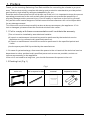
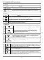
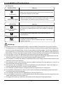
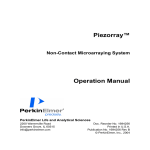
SOLACE SERIES
SWIMMING POOL DEHUMIDIFIER
Installation & Operation Manual
CONTENT
1. Preface
1
2. Safety Precautions
2
2.1 Marks
2
2.2 Icons
2
2.3 Warnings
2
2.4 Attention
3
3. Specifications
4
3.1 Parameters
3.2 Performance Curve
4
5
3.3 Dimensions
6
3.4 Working Principle
6
3.5 Product Features
7
3.6 Hygrostat Control
4. Installation
7
8
4.1 Installation Precautions
8
4.2 Positioning
8
4.3 Minimum Installation Distances
8
4.4 Drainage
5.Usage
5.1 Instruction for Operation Panel
5.2 Operation Instruction
6.Maintenance
9
10
10
11
13
6.1 Maintenance
13
6.2 Troubleshootings
15
7.Appendix
16
7.1 PCB I/O Port
16
7.2 Wiring Diagram
17
1. Preface
Thank you for choosing Swimming Pool Dehumidifier for controlling the climate in you pool
area. This product strictly complies with design and production standards to provide perfect
performance, high reliability and good adaptability for you.
Read the entire manual before the initial start-up of the unit. It is important to know the correct
operating procedures for the unit and all safety precautions to prevent the possibility of
property damage and/or personal injury. Do not modify or intervene on the unit by yourself
only as this could create dangerous situations and the manufacturer will not be responsible
for any damage caused.
This instruction must be kept carefully and must always accompany the appliance. If it is
lost or damaged, please contact the local technical service center.
1.1 Fail to comply with these recommendations will invalidate the warranty.
¡This unit must be installed by an authorized installer.
¡All repair or maintenance interventions must be performed by the technical service
department or by professionally qualified personnel.
¡All repair or maintenance interventions must be performed in the specified period and
times.
¡Use the spare parts ONLY provided by the manufacturer.
1.2 In case of system leakage, disconnect the power to the unit and call the technical service
department or other professionally qualified personnel as soon as possible, and do not
intervene personally on the appliance.
If the unit is not used for a long time, you should disconnect the power to the unit.
1.3 Packing List (Fig.1)
Fig.1
main unit
manual
wall suspension bar
1
expansion bolts
2. Installation Precautions
2.1 Marks
Meaning
Mark
A wrong operation may lead to death or heavy injury on people.
WARNING
ATTENTION
A wrong operation may lead to harm to people or loss of property.
2.2 Icons
Icon
Meaning
Prohibition. What is prohibited will be nearby this icon.
Compulsory implement. The listed actions need to be taken.
Attention(include warnings)
Please pay attention to what is indicated.
MOVE AND REPAIR
OPERATION
INSTALLATION
2.3 War n ings
PROFESSIONAL
INSTALLER IS REQUIRED
EARTHING
IS REQUIRED
SHUT OFF
THE POWER
PROHIBIT
ENTRUST
Confirm whether wether the unit is with correct earthing. Wrong
connection may cause personnel shock.
Do not put fingers or others into the fan or evaporator of the unit,
otherwise harm may be occurred.
PROHIBITION
ENTRUST
Entrust a specialized personnel for installation. Wrong installation
may cause leakage, personnel electric shock or fires.
When there is something wrong or strange smell from the unit, please cut
off the power to the unit immediately.
When the unit needs to be moved or installed again, please entrust
dealer or qualified person to carry it out. Improper installation may lead to
water leakage, electrical shock, injury or fire.
It is prohibited to repair the unit by the user himself, otherwise electrical
shock or fire may occur.
When the unit needs to be repaired, please entrust dealer or qualified
person to carry it out. Improper movement or repair on the unit may lead to
water leakage, electrical shock, injury or fire.
2
2. Installation Precautions
2.4 Attention
Meaning
INSTALLATION
Fix the unit
Need circuit breaker
Make sure that the basement of the unit is strong enough
to avoid any decline or fall down.
Make sure that there is circuit breaker for the unit. Lack of
circuit breaker can lead to electrical shock or fire.
OPERATION
Ö Ì µ ° ×
Check the installation
basement
Meaning
Please check the installation basement regularly to avoid
any decline or damage which may hurt people or damage
the unit.
Please disconnect the power to the unit for clean or
maintenance.
Disconnect the power
Prohibit
Please use the suitable fuse.
If copper or icon is used to replace the fuse, it will cause
failure, even fire.
Warinng:
Remember that some fundamental safety rules should be followed when using this product:
1. This appliance is not intended for use by persons(including children) with reduced physical,
sensory or mental capabilities, or lack of experience and knowledge, unless they have been
given supervision or instruction concerning use of the appliance by a person responsible for
their safety. Children should be supervised to ensure that they do not play with the appliance.
2. It is forbidden to touch the appliance with wet hands or body when barefoot.
3. It is forbidden to carry out any cleaning before having disconnected the appliances from the
electricity mains supply by turning the system master switch to OFF.
4. It is forbidden to modify the safety or adjustment devices or adjust without authorization and
indication of the manufacturer.
5. It is forbidden to pull, cut or knot the electrical cables coming out of the appliance, even if it is
disconnected from the mains supply.
6. If the supply cord is damaged, it must be replaced by the manufacturer, its service agent or
similarly qualified persons in order to avoid a hazard.
7. It is forbidden to poke objects or anything else through the inlet or outlet grills.
8. It is forbidden to dispose of or leave in the reach of children the packaging materials which
could become a source of danger.
9. It is forbidden to climb onto the appliance or rest any object on it.
10. It is forbidden to touch the unit with hands directly as the external parts of the appliance can
reach temperatures of more than 70→.
11. The appliance shall be installed in accordance with national wiring regulations.
3
3. Specifications
3.1 Parameters
Swimming Pool Dehumidifier
Model
Unit
Rated Capaclty
L/h
1.25
1.75
2.5
m 3 /h
400
500
750
dB(A)
44
46
47
Air Volume
Nolse Level
Solace 1.25 Solace 1.75 Solace 2.5
Rated Voltage/Freq
/
Rated Power Input
kW
0.78
1.08
1.55
A
3.3
4.7
6.7
kW
1.1
1.4
2.1
A
4.9
6.1
9.1
%RH
40~100
40~100
40 ~ 100
Rated Running Current
Max Power Input
Max Running Current
Relative Humidity
Temperature
Dimensions(L/W/H)
Net Weight
Refrigerant/Volume
Operation Pressure ( High Side)
Operation Pressure( Low Side)
Condensation Pipe Diameter
220-240V~/50Hz
10 ~ 36
¡
See 3.3
mm
See nameplate/ package label
kg
R410A/600g
/
R410A/800g R410A/1050g
4.4
4.4
4.4
Mpa
2.1
2.1
2.1
mm
16
16
16
MPa
Relative humidity: 60%.
Test condition: Ambient temperature: 27→,
4
3. Specifications
3.2 Performance Curve
C
40%RH
0
0.5
0
60%RH
80%RH
40
35
30
25
20
15
10
5
l/h
2.5
0
0
1.0
1.5
Solace 1.25
40%RH
C
2.0
60%RH
80%RH
40
35
30
25
20
15
10
5
0
0
0.5
1.0
1.5
2.0
2.5
3.0
l/h
3.5
Solace 1.75
0
40%RH
C
60%RH
80%RH
40
35
30
25
20
15
10
5
0
0
0.5
1
1.5
2
2.5
Solace 2.5
5
3
3.5
l/h
4
3. Specifications
3.3 Dimensions
3.3.1 Model: Solace 1.25/1.75/2.5
Fig.2
Model
Solace 1.25
Solace 1.75
Solace 2.5
Length: A
1300
1500
1500
3.4 Working Principle:
The unit works by drawing moist air over a refrigerated coil with a small fan. The cold coil of
the refrigeration device condenses the water, which is removed, then the air is reheated by the
hot coil. This process works most effectively with higher ambient temperatures with a high
dew point temperature(Fig.3).
Warmer & dehumidified air
Fig.3
Warm damp air
6
3. Specifications
3.5 Product Features
3.5.1 Ultra-low noise
With the advanced air ducting technology and the super quiet cross-flow fan, the unit can
operate with ultra-low noise.
3.5.2 Ultra-thin casing
With the ultra-thin casing of 200mm, which is the result of compact design, the unit can
save more space for you when it is compared with the common dehumidifierswith the
thickness of 400mm.
3.5.3 Fashionable appearance
With noble &fashion arc frame and elegant & graceful snow white color, the unit will be
perfectly combined with your pool house.
3.5.4 Newly design controller.
With simple operating display, the newly developed controller makes the unit operation
easier and more user-friendly.
3.6 Hygrostat Control
3.6.1 The dehumidifier is controlled by a built-in hygrostat set on one side of the unit and
the target RH value can be set ranges from 30% to 90%.
3.6.2 The unit will not start to dehumidify until the actual RH is beyond the setting value.
3.6.3 We recommend that an external hygrostat should be installed to ensure a constant
measure of the humidity in the pool area.
3.6.4 The location of hygrostat is as the following Fig.4:
Fig.4
Built-in hygrostat
7
4. Installation
4.1 Installation Precautions
4.1.1 To ensure that the installation is performed correctly and that the appliance will perform
perfectly, please carefully follow the instructions indicated in this manual. Fail to respect the
rules indicated not only can cause malfunctions of the appliance but also invalidate the
warranty, hence our company shall not respond for any damage to persons, animals or
property.
4.1.2 It is important that the electrical installation is made according to the laws in force,
respects the data indicated in the technical sheet and the unit is correctly earthed.
4.1.3 The appliance must be installed in a position that allows the routine maintenance, such
as filter cleaning.
4.2 Positioning
4.2.1 Avoid installing the unit in proximity to:
-positions subject to exposure to direct sunlight;
-sources of heat;
-in places with oil fumes
-places subject to high frequencies.
4.2.2 Make sure that:
-the wall on which the unit is to be installed is strong enough to support the weight;
-the part of the installation wall does not have pipes or electric wires passing through;
-the installation wall is perfectly flat;
-there is an area free of obstacles which could interfere with the inlet and outlet air flow;
-it is preferably that there is an outside perimeter-wall to allow the discharge of condensation
outside;
4.3 Minimum Installation Distances
4.3.1 When the unit is for wall-mounted installation, please take off the all feet for floor
standing installation.
4.3.2 Fig. 5 indicates the minimum mounting distances between the wall-mounted swimming
pool dehumidifier and furniture in the room.
0.5 m
0.5 m
0.2 m
0.2 m
Fig.5
8
4. Installation
4.3.3 Wall mounted installation
Insert 5 expansion bolts into holes which are bored by ¦ 10 drill and fix the wall suspension
bar horizontally(Fig.6).
Wall suspension bar
Expansion bolt
Wall
Fig.6
4.4 Drainage
Select a suitable size hose to connect to the built-in hose if it is needed(Fig.7).
Condensate drainage hose
Fig.7
Attention£
If the condensation water discharges directly into a container, the condensate outlet
should above the container to avoid immersing in the container.
9
5. Usage
5.1 Instruction for Operation Panel
%RH
Dehumidifying
ÖÈ
µ·
Defrosting
ÖÀ
Tips:
When the unit is switched on, "8.8" will firstly be shown on the display. Then "1.0" will be
shown which stands for the version of the program. After that, you will find actual relative
humidity of the room air on the display.
5.1.1 Buttons
ON/OFF
Press this butto n to turn the unit on/off.
UP
Press this butto n once to check the target setti ng value of relative humidity;
Press it again can increase the target setti ng value.
DOWN
Press this butto n once to check the target setti ng value of relative humidity;
Press it again can decrease the target setti ng value.
10
5. Usage
5.2 Operation Instruction
5.2.1 Unit ON/OFF
You can turn ON/OFF the unit by just pressing "
" when the unit is connected to the power.
When the unit is turned on, you can see the actual relative humidity shown on the display. At
the same time, the mode indicator and the light for the ON/OFF button will be on.
Actual relative humidity
%RH
%RH
Press "
"to turn
the unit ON/OFF
ÖÈ
µ·
ÖÀ
Ö·
µ·
µ·
ÖÀ
ÖÈ
ÖÈ
The selected mode
ÖÀ
OFF
ON
5.2.2 Set the target value of relative humidity
Actual relative humidity
of room air
Target relative humidity
%RH Press " "
%RH Press" "
µ·
ÖÈ
ÖÀ
or " "
to check the
target relative
humidity
µ·
ÖÈ
ÖÀ
or " " again
to change the
target relative
humidity
%RH
µ·
ÖÈ
ÖÀ
Tips£
1. After the target value has been changed, if there is no operation in 5s, the value will be saved
and the controller will be back to the main interface.
2. After the target value has been changed, when the unit is restarted, system will operate at
the new target value.
11
5. Usage
5.2.3 Dehumidifying mode
When the unit is in dehumidifying mode, the LED for icon"
" lights up, and£
1. If the hygrostat detects that A(actual relative humidity of room air) ¡ TRH(target
relative humidity) + 5%RH, and this condition has lasted for 30s, the unit will start to
dehumidify.
2 .If the hygrostat detects that A(actual relative humidity of room air) ¡ TRH(target relative
humidity) - 5%RH, and this condition has lasted for 3mins, the unit will halt the
dehumidifying..
5.2.4 Defrosting mode
When the ambient temperature is low, for example, 11¡, and after the unit has worked for a
period of time, possibly, the evaporator will start to ice up . So the unit will switch to defrosting
mode automatically. During defrosting, the LED for icon "
" lights up . When defrosting is
over, the unit will return to the dehumidifying mode, and operate according to the condition
mentioned above.
%RH
Ö·
µ·
µ·
ÖÀ
ÖÈ
ÖÈ
ÖÀ
5.2.5 Malfunction
Operation panel will display the failure codes when the unit gets some malfunctions. Please
refer to page15 to check the meaning of failure codes.
%RH
Ö·
µ·
µ·
ÖÀ
ÖÈ
ÖÈ
ÖÀ
12
6. Maintenance
6.1 Maintenance
To guarantee the unit reliable and security operation for a long time, it is suggested to maintain and clean
up the unit every six months.
. Please take the following steps to clean up the strainer regularly:
1)Pull out the grill(A) from the upside of it(Fig.8);
2)After that, pull out the grill(Fig.9),then lift the grill upward(Fig.10);
3)Move away the grill(Fig.11)and take out strainer(Fig.12),then wash the strainer with water ( Fig.13 ).
Fig.8
Fig.9
A
Fig.11
Fig.10
Fig.12
Fig.13
13
6. Maintenance
4)Set the filter net and the air return grille to the original place. (Fig.14)。
5)Clean up the unit outer with soft and damp rag(Fig.15). To protect the paint-coat of the
unit, please don’
t use rough sponge or corrosive detergent to do these.
Fig.15
Fig.14
Warning£Cut off power supply before cleaning or maintaining the unit.
14
6. Maintenance
6.2 Troubleshootings
Press the key of "UP" or "Down" to check that if there are more failure codes.
You can find solutions to the problems according to the codes.
Malfunction
Code
Reason
Solution
High pressure protection
has appeared 3 times in
30mins.
P1
High pressure protection
is too frequently.
High pressure protection
P2
Discharge pressure
is too high
Condenser outlet
temp. overhigh
P3
Condenser coil temp.
is too high
Evaporator outlet temp.
sensor failure
P5
This temp. sensor is
broken or in short circuit
Check or replace
this temp. sensor
Evaporator inlet temp.
sensor failure
P6
This temp. sensor is
broken or in short circuit
Check or replace
this temp. sensor
Condenser outlet temp.
sensor failure
P7
This temp. sensor is
broken or in short circuit
Check or replace
this temp. sensor
Humidity sensor failure
P8
This humidity sensor is
broken or in short circuit
Check or replace this
humidity sensor
Motor feedback
signal failure
E0
The feedback wiring is in
bad connection.
Or fan motor is damaged.
1.Check the feedback
wiring of fan motor.
2.Or replace the fan
motor.
Check the below
solutions to failure
P1/P2/P3
Solution to failure P1/P2/P3
1. If P1/P2/P3 appears together with other failures, please solve the others first.
2. If there is no other failures of P3~E0, and P1 & P2 still exist, please disconnect the power to
the unit and connect again after 1 hour.
3. If only P3 exists, please keep the fan running for 30min. If P3 still exist after the running,
please disconnect the power to the unit and connect again after 1 hour.
Note: Please contact with Technical Service Assistance when failures can not be solved.
15
7. Appendix
7.1 PCB I/O Port
NET2
CN1
TEMP1
HUMI02
HUMI01
PROG1
TEMP2
CN4
FM
NET1
CN7
EEV
L_Valve
L_Comp
L
N1
N_Comp
N_Valve
Explanation£
NO
Ports
Meaning
1
Cn1
To operation panel
CN4
2
NET1
Reserved
NET2
3
4
5
FM
To fan motor(DC)
TEMP1
To evaporator inlet/outlet temp. sensor
TEMP2
To condenser outlet temp. sensor
HUMI01
To the build-in hygrostat
6
HUMI02
To the external hygrostat (optional)
7
CN7
To high pressure protection switch
8
EEV
To electronic expansion valve
9
PROG1
Program burning port
10
L
N1
N_Comp
N_Valve
To the Live Wire of power supply
L_Comp
To the Live Wire of compressor
11
12
13
Neutral Wire
16
7. Appendix
7.2 Wiring Diagram
FM
Operation Panel
5K
EvIT
t t
14
EvOT
5K
SS
TEMP1
CN1
HUMI0 2
RHS
HUMI0 1
PACC1001
WHT
FM
BLK
EEV
t
TEMP2
BLU
YEL
5
CdOT
5K
EEV
RED
CN7
CR
CC
RED
N
L_Comp
Y/G BLU
CS
WHT
C1
HPS
BLK
N
CS
CR
COMP
BRN
L
N_Comp N1 N_Valve L
PGND
TO POWER SUPPLY
220-240V~/50Hz
CdOT£ Condenser Outlet Temperature
EvOT£ Evaporator Outlet Temperature FM£ Fan Motor(DC)
EvIT£ Evaporator Inlet Temperature
SS£ Sensitive Switch
HPS£ High Pressure Protection Switch EEV£ Electronic Expansion Valve
HUMIO 2 £Can connect to an external RHS RHS£ Sensor of Relative Humidity
CODE£ 201210220001
17
Code:20121115-0004