1
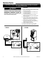
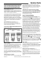
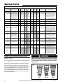
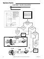
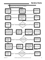
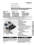
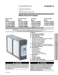
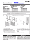
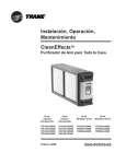
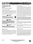
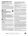
Service Facts
EAC- SF- 1 3
Whole House Electronic Air Cleaner
Upflow Furnace Models
Downflow Furnace Models
Air Handler Models
50 Hz Air Handler Models
*FD145CLFR000D
*FD175CLFR000D
*FD210CLFR000D
*FD245CLFR000D
*FD14DCLFR000D
*FD17DCLFR000D
*FD21DCLFR000D
*FD24DCLFR000D
*FD175CLAH000D
*FD215CLAH000D
*FD235CLAH000D
*FD260CLAH000D
TFD215CLAH005D
TFD235CLAH005D
TFD260CLAH005D
* May be "A" or "T"
ALL phases of this installation must comply with NATIONAL, STATE AND LOCAL CODES
IMPORTANT — This Document is customer property and is to remain with this unit.
Please return to service information pack upon completion of work.
4
1
COMPONENTS OF THE AIR CLEANER
5
9
6
3
3
8
AIR
FLOW
7
2
12 3
1
1) PRE-FILTER - traps large particles such as hair and lint before
they can enter the COLLECTION CELL section.
2) FIELD CHARGER - Charges the contaminants. Only to be
serviced by a qualified technician.
3) COLLECTION CELL (2) - removes and collects very small
impurities from the air.
4) CABINET - mounts between the furnace/air handler and return
air duct work and houses the COLLECTION CELLS, FIELD
CHARGER and PRE-FILTER.
5) POWER DOOR - the solid state power supply components
that convert the 24 Volt AC to the high-voltage, direct current
required to power the FIELD CHARGER and COLLECTION
! WARNING
▲
This information is for use by individuals having adequate
backgrounds of electrical and mechanical experience. Any
attempt to repair a central air conditioning product may result in personal injury and/or property damage. The manufacturer or seller cannot be responsible for the interpretation of this information, nor can it assume any liability in connection with its use.
© Trane 2011
6)
7)
8)
9)
CELLS. Allows access to the COLLECTION CELLS, FIELD
CHARGER and PRE-FILTER.
TRANSFORMER - supplies 24 Volts to the indoor unit and Air
Cleaner (not available with 50 Hz units)
24 VOLT POWER / CONTROL CABLE
GASKET, LITERATURE AND HARDWARE PACKET
UPFLOW AIR HANDLER BAFFLE - This baffle is only included
with Air Handler models. See note below.
NOTE: Be careful not to discard the baffle. It is located under
the collection cells in the shipping box.
! CAUTION
▲
RECONNECT ALL GROUNDING DEVICES.
All parts of this product that are capable of conducting electrical current are grounded. If grounding wires, screws,
straps, clips, nuts, or washers used to complete a path to
ground are removed for service, they must be returned to their
original position and properly fastened.
Service Facts
INTRODUCTION
The whole house air cleaner can be installed either as
part of a Communicating heating and air conditioning
system or as part of a traditional 24 volt system.
When installed as part of a Communicating System in
which the indoor unit, outdoor unit, and 900 series
comfort control are equipped with our exclusive
Communicating technology, this system performs a
continuous loop of system diagnostics and data output.
The Communicating System monitors itself and quickly
identifies any operational faults, automatically issuing a
service alert if needed.
Power Button
The whole house air cleaner can also be installed as
part of a traditional 24 volt heating and air conditioning
system.
Amber Light
MODES OF OPERATION
The whole house air cleaner can be connected in one of
two modes of operation; either a 24 V mode or a
communicating mode. To know how the whole house air
cleaner is set up, reference Figure 1a to find the amber
light.
A steady amber light indicates that the unit is wired in
the 24 V mode.
A blinking amber light indicates that the unit is wired in
the communicating mode.
No light present means that the unit is not connected.
! CAUTION
▲
SAFETY HAZARD
Sharp Edge Hazard. Be careful of sharp edges on equipment or any cuts made on sheet metal while installing or
servicing. Personal injury may result.
ELECTRICAL CONNECTIONS
The air cleaner requires 24 VAC power and indoor fan
signal to operate. A transformer adequately sized to
power both the system and air cleaner is provided with
the air cleaner. Remove the transformer in the indoor unit
and replace with the transformer provided.
NOTE: A 50 VA transformer is required for Trane/
American Standard Heating & Air Conditioning
furnace applications and 75 VA required for Trane/
American Standard Heating & Air Conditioning air
handler applications. If the indoor air handler
already has a properly sized transformer, no
replacement is required.
NOTE: Trane/American Standard Heating & Air
Conditioning dual circuited air handlers matched
with heat pumps and Trane/American Standard
Heating & Air Conditioning oil furnaces will require
an accessory Transformer KIT# BAYTRANS12024◆ to
power the air cleaner. Do NOT replace air handler
transformer with the transformer supplied with the
air cleaner.
2
Plug Power Cord
in here
1a
NOTE: When more than one whole house air cleaner
is used, the 24 volt transformer which supplies
power to the air cleaner will need to be increased by
25 VA for each additional air cleaner added.
NOTE: Provide adequate strain relief for the low
voltage cable at the indoor unit.
NOTE: Wiring penetration must be sealed.
! CAUTION
▲
DO NOT attach the power/control cable to a 120 Volt
EAC tap. The air cleaner uses 24 Volt power. Failure
to use 24 VAC results in permanent damage to the air
cleaner.
• Plug the air cleaner power/control cable into the air
cleaner door and route the cable into the indoor unit
low voltage wiring location.
• Connect the power/control wiring per Figure 2.
NOTE: For non-Trane/American Standard Heating & Air
Conditioning systems order a 120 VAC to 24 VAC
transformer, KIT# BAYTRANS12024◆ to provide 24 volt
power only to the air cleaner. Access to 120 VAC outlet
is required.
• Connect the power/control wiring per Figure 3.
NOTE: Trane/American Standard Heating & Air
Conditioning Communicating Furnaces require KIT #
BAYACCECOMM101.
NOTE: Wiring diagrams for the Communicating Air
Handler, Communicating Furnaces and Oil Furnace are
on pages 3, 4-5 and 6 respectively.
Numbers in [brackets] are for 50 Hz international systems.
EAC-SF-13
Diagram
2 Wiring
Communicating Mode
RED
RED
BLUE
Unused
GREEN
Data Line
BLACK
RED
WHITE
BLACK
WHITE
D
BLACK
NOTE: The Black wire must be
connected to chassis ground to
ensure proper operation.
BROWN
BROWN
BROWN
BROWN
BLUE
GREEN
BLUE
GREEN
GRD
WHITE
Unused
Air Handler may not have a Low Voltage Terminal board. Connect Electronic Air Cleaner wires to
the Air Handler Low Voltage Color coded wires.
Install Transformer, one is supplied with the Electronic Air Cleaner, in the Furnace or Air Handler.
BAYTRANS12024◆
◆ Transformer
• Transformer must have a grounded 120 VAC
power source. Do not defeat ground plug on the
transformer.
• Mount transformer to building structure with the
four provided wood screws.
NOTE: BAYTRANS12024C complies with the California
Code of Regulation,Title 20, Sections 1601 through
1608 dated December 2006. BAYTRANS12024A with
vendor’s manufacturing date codes after 0625 (YYWW)
cannot be installed in California because the transformer
does not satisfy the requirements set forth by California
Code of Regulations, Title 20, Sections 1601 through
1608 dated December 2006.
Furnace / Air Handler
24 V
RED
R
Common
BLUE
B
Furnace
Heating Signal
WHITE
W
Fan Signal
GREEN
G
Data Line
BROWN
D
BLUE
GREEN
BLUE
BROWN
Unused
WHITE
BLACK
RED
WHITE
Unused
GREEN
BROWN /
Dataline
Indoor Unit
24 V Terminal Strip
The ◆ represents an alpha character.
Transformer not applicable to 50 Hz units.
Wiring Diagram
3 for 24 V Mode
BLUE
GREEN
BROWN
BLACK
RED
WHITE
NOTE: The Black wire must be
connected to chassis ground to
ensure proper operation.
Air Handler may not have a Low Voltage Terminal board. Connect Electronic Air Cleaner wires to
the Air Handler Low Voltage Color coded wires.
Install Transformer, one is supplied with the Electronic Air Cleaner, in the Furnace or Air Handler.
BAYTRANS12024◆
◆ Transformer
• Transformer must have a grounded 120 VAC
power source. Do not defeat ground plug on the
transformer.
• Mount transformer to building structure with the
four provided wood screws.
NOTE: BAYTRANS12024C complies with the California
Code of Regulation,Title 20, Sections 1601 through
1608 dated December 2006. BAYTRANS12024A with
vendor’s manufacturing date codes after 0625 (YYWW)
cannot be installed in California because the transformer
does not satisfy the requirements set forth by California
Code of Regulations, Title 20, Sections 1601 through
1608 dated December 2006.
Transformer not applicable to 50 Hz units.
Furnace / Air Handler
24 V
RED
R
Common
BLUE
B
BLUE
Furnace
Heating Signal
WHITE
W
WHITE
Fan Signal
GREEN
G
GREEN
BLUE
GREEN
BROWN
BLACK
RED
WHITE
BROWN /
Dataline
Indoor Unit
24 V Terminal Strip
The ◆ represents an alpha character.
Service Facts
ELECTRICAL CONNECTIONS TO A COMMUNICATING SYSTEM AIR HANDLER
IN CONVENTIONAL 24 V MODE
! WARNING
▲
5)
6)
Replace the Communicating control box cover.
Locate the white wire coming from the
Communicating System Air Handler PCB labeled
“EAC”. The wire will have a male spade terminal
connected to it and a female spade terminal
inserted into the male terminal. Remove the
female spade terminal and crimp it to the green
wire on the air cleaner harness.
7) Connect the green wire from the air cleaner
harness to the white wire on the Communicating
Systems Air Handler.
8) Using the wire harness supplied with the air
cleaner, connect the Red and Blue wires from the
air cleaner harness to “R” and “B” on the Indoor
Unit 24V Terminal Strip respectively.
9) Connect the Black wire from the air cleaner wire
harness to earth ground by attaching the wire to a
grounded screw that is connected to the metal air
handler chassis.
10) Replace the blower access panel.
11) Reconnect electrical power to the air handler.
HAZARDOUS VOLTAGE! DISCONNECT ALL ELECTRIC
POWER, INCLUDING REMOTE DISCONNECTS BEFORE
SERVICING. FOLLOW PROPER LOCKOUT/TAGOUT
PROCEDURES TO ENSURE THE POWER CAN NOT BE
INADVERTENTLY ENERGIZED. FAILURE TO
DISCONNECT POWER BEFORE SERVICING COULD
RESULT IN DEATH OR SERIOUS INJURY.
PROCEDURE:
1)
2)
3)
4)
Remove electrical power going into the air handler.
On the communicating systems air handler, remove
the blower access panel.
Remove the communicating control box cover.
Locate the red jumper wire which is attached from
EAC to R on the Communicating Systems PCB.
Confirm it is connected. If there is not a jumper wire
installed, then one must be installed in this location
in order for the air cleaner to function properly.
Control box panel cover
(Shown removed)
Detach female spade terminal
from white EAC wire and
crimp to green wire
BEFORE
24V RED
jumper wire
from EAC to R
AFTER
EAC
WHITE
WHITE
R
GREEN
GREEN
EAC
WHITE
BK
R
O
G
Y1
Y2
D
B
W1
W2
W3
PCB Detail
GREEN
BK
R
D
O
B
G
W1
Y1
W2
Y2
W3
Indoor Unit
24V
Terminal
Strip Detail
For use with Whole House
Air Cleaner
BLACK
GRD
Power / Control
Wiring Cable and Plug
Air Cleaner
Plug
GREEN
BLUE
RED
WHITE
Unused
4
BROWN /
Future Use
Numbers in [brackets] are for 50 Hz international systems.
EAC-SF-13
Service Facts
ELECTRICAL CONNECTIONS TO A STANDARD 24 VOLT AIR HANDLER
! WARNING
▲
HAZARDOUS VOLTAGE! DISCONNECT ALL ELECTRIC
POWER, INCLUDING REMOTE DISCONNECTS BEFORE
SERVICING. FOLLOW PROPER LOCKOUT/TAGOUT
PROCEDURES TO ENSURE THE POWER CAN NOT BE
INADVERTENTLY ENERGIZED. FAILURE TO
DISCONNECT POWER BEFORE SERVICING COULD
RESULT IN DEATH OR SERIOUS INJURY.
GAM5 / A/TAM4
A/TAM7
Field wiring
W3
W2
W1
BK
G
Y2
YI (In)
O
R
B
YO (Out)
W3
W2
W1
G
YI
O
R
B
YO
For use with Whole House
Air Cleaner
BLACK
GRD
Power / Control
Wiring Cable and Plug
Power / Control
Wiring Cable and Plug
GREEN
BLUE
BLUE
RED
RED
Unused
EAC-SF-13
GRD
Air Cleaner
Plug
GREEN
WHITE
For use with Whole House
Air Cleaner
BLACK
Air Cleaner
Plug
WHITE
BROWN /
Future Use
Unused
BROWN /
Future Use
Numbers in [brackets] are for 50 Hz international systems.
5
Service Facts
ELECTRICAL CONNECTIONS TO A COMMUNICATING SYSTEMS AIR HANDLER
IN COMMUNICATING MODE
PROCEDURE:
! WARNING
▲
HAZARDOUS VOLTAGE! DISCONNECT ALL ELECTRIC
POWER, INCLUDING REMOTE DISCONNECTS BEFORE
SERVICING. FOLLOW PROPER LOCKOUT/TAGOUT
PROCEDURES TO ENSURE THE POWER CAN NOT BE
INADVERTENTLY ENERGIZED. FAILURE TO
DISCONNECT POWER BEFORE SERVICING COULD
RESULT IN DEATH OR SERIOUS INJURY.
4TEE3C
1)
2)
Remove electrical power going into the air handler.
On the communicating systems air handler, remove
the blower access panel.
3) Connect Red stripped wire to "R" terminal on the
air handler terminal strip.
4) Connect Blue stripped wire to "B" terminal on the
air handler terminal strip.
5) Connect the brown wire from the air cleaner
harness to the "D" terminal on the Communicating
Systems Air Handler.
6) Connect the Black wire from the air cleaner wire
harness to earth ground by attaching the wire to a
grounded screw that is connected to the metal air
handler chassis or control plate assembly.
7) The Green and White wires on the air cleaner
wiring harness are unused in this application and
should be insulated separately.
8) Replace the blower access panel.
9) Reconnect electrical power to the air handler.
10) Check air cleaner and air handler operation.
A/TAM8
Control box panel cover
(Shown removed)
Indoor Unit
24V Terminal
Strip Detail
BK
R
O
G
Y1
Y2
BK
R
D
D
B
W1
W2
O
B
G
W1
Y1
W2
Y2
Y1
O
R
B
D
Y2
W3
W3
BLACK
Black wire to
chassis
ground
For use with Whole House
Air Cleaner
GRD
Power / Control
Wiring Cable and Plug
BLACK
Air Cleaner
Plug
For use with Whole House
Air Cleaner
GRD
BLUE
Power / Control
Wiring Cable and Plug
RED
BROWN /
Dataline
WHITE
GREEN
Unused
Unused
Air Cleaner
Plug
BLUE
RED
BROWN /
Dataline
WHITE
GREEN
Unused
6
Numbers in [brackets] are for 50 Hz international systems.
Unused
EAC-SF-13
Service Facts
ELECTRICAL CONNECTIONS TO A COMMUNICATING FURNACE IN 24 V MODE
! WARNING
▲
9.
HAZARDOUS VOLTAGE! DISCONNECT ALL ELECTRIC
POWER, INCLUDING REMOTE DISCONNECTS BEFORE
SERVICING. FOLLOW PROPER LOCKOUT/TAGOUT
PROCEDURES TO ENSURE THE POWER CAN NOT BE
INADVERTENTLY ENERGIZED. FAILURE TO DISCONNECT
POWER BEFORE SERVICING COULD RESULT IN DEATH
OR SERIOUS INJURY.
PROCEDURE:
1.
2.
3.
4.
5.
6.
7.
8.
10.
11.
Remove electrical power going into the furnace.
Remove blower door to up-flow or down-flow furnace.
Remove the two screws that secure the IFC platform to the
underside of the blower deck on an up-flow furnace or the 3
screws that secure the IFC platform to the top panel on a
down-flow furnace.
Carefully remove the IFC platform from the furnace.
On both the up-flow and down-flow furnaces, mount the 50VA
transformer supplied in the packaging with the air cleaner
onto the bottom of the IFC platform. Screws and pilot holes
are provided. See figure.
Remove wiring from existing 35VA transformer and reconnect
to the 50VA transformer. Note the polarity of the wires and
reconnect to the appropriate terminals. See diagram
Remove the EAC-H 115VAC and EAC-N wires (white and
black) out of the junction box and pull them through the
grommet in the blower deck. Attach two supplied ¼” insulated
female quick connect terminals by stripping the wires and
crimping the terminals onto the wires. Attach these wires to
the 115V terminals of the 35VA transformer as shown in the
diagram.
Remove the wiring harness supplied with the air cleaner from
the packaging. Attach a supplied 3/16” insulated female quick
connect terminal to the blue wire and the green wire.
12.
13.
14.
15.
16.
17.
18.
19.
Attach the blue wire from the air cleaner wiring harness to the
open tab on the piggyback terminal supplied in the
BAYACCECOMM101. Attach piggyback terminal to the 35VA
transformer terminal “C” (Common).
Insert the 12” blue stripped wire under the terminal strip
screw marked “B/C” on the IFC control board. If the application also includes an outdoor unit (communicating or noncommunicating), the B/C terminal will require 3 wires
connected. For this connection, rather than connecting the
three wires to the low voltage terminal strip on the furnace
IFC, create a pigtail using a short length of thermostat wire
and a wire nut (field supplied) to attach to the B/C terminal.
Connect the green wire from the air cleaner wiring harness to
the 24V terminal on the 35VA transformer labeled “RD”. See
diagram.
Insert the red stripped wire from the air cleaner wiring
harness under the IFC control board terminal screw marked
“R”. See diagram.
Attach the black stripped wire from the air cleaner wiring
harness directly to ground with a screw on the furnace
chassis. See diagram.
Once all of the connections have been completed, remount
the IFC control platform into the furnace.
Secure any loose wiring with wire ties.
The brown and white wires from the EAC wiring harness are
unused in this application and should be insulated. See
diagram.
Replace the furnace door.
Reconnect electrical power to the furnace.
Check both furnace and air cleaner operation per the furnace
and air cleaner installer guides.
BILL OF MATERIALS:
QTY: 2
QTY: 1
QTY: 2
QTY: 2
QTY: 1
EAC-SF-13
Screw
4" Insulated Copper Wire –
Blue (18 AWG, AWM)
1/4” Insulated Female Quick
Connect Terminal
3/16" x 0.020" Insulated Female
Quick Connect Terminal
3/16" x 0.020" Receptacle & Tab
These instructions and listed parts are included in KIT# BAYACCECOMM101
Numbers in [brackets] are for 50 Hz international systems.
7
Service Facts
ELECTRICAL CONNECTIONS TO A COMMUNICATING SYSTEM FURNACE
! WARNING
▲
HAZARDOUS VOLTAGE! DISCONNECT ALL ELECTRIC
POWER, INCLUDING REMOTE DISCONNECTS BEFORE
SERVICING. FOLLOW PROPER LOCKOUT/TAGOUT
PROCEDURES TO ENSURE THE POWER CAN NOT BE
INADVERTENTLY ENERGIZED. FAILURE TO DISCONNECT
POWER BEFORE SERVICING COULD RESULT IN DEATH
OR SERIOUS INJURY.
PROCEDURE:
1.
2.
3.
4.
5.
8
Remove electrical power going into the furnace.
Open blower door to upflow or downflow furnace.
Disconnect all wires on the 35VA transformer.
Remove the 35VA transformer from the IFC platform.
Mount the 50 VA transformer supplied in the packaging with
the air cleaner onto the IFC platform where the 35VA
transformer was previously located. Use the sheet metal
screws supplied with the air cleaner to mount the 50VA
transformer. Reconnect the 115V and 24V wires that were
connected to the 35VA transformer onto the 50 VA
transformer.
6.
7.
8.
9.
10.
11.
12.
13.
Connect Red stripped wire to "R" terminal on the furnace control
board.
Connect Blue stripped wire to "B" terminal on the furnace control
board.
Connect Brown stripped wire to "D" terminal on the furnace
control board.
Attach the black stripped wire from the air cleaner wiring harness
directly to ground with a screw in the chassis.
The green and white wires on the air cleaning wiring harness are
unused in this application and should be insulated.
Replace door on furnace.
Reconnect electrical power to the furnace.
Check both furnace and air cleaner operation per the furnace and
air cleaner installer guides.
Numbers in [brackets] are for 50 Hz international systems.
EAC-SF-13
Service Facts
ELECTRICAL CONNECTIONS TO AN OIL FURNACE
! WARNING
▲
HAZARDOUS VOLTAGE! DISCONNECT ALL ELECTRIC
POWER, INCLUDING REMOTE DISCONNECTS BEFORE
SERVICING. FOLLOW PROPER LOCKOUT/TAGOUT
PROCEDURES TO ENSURE THE POWER CAN NOT BE
INADVERTENTLY ENERGIZED. FAILURE TO
DISCONNECT POWER BEFORE SERVICING COULD
RESULT IN DEATH OR SERIOUS INJURY.
Refer to the diagrams below for proper connections
to an oil furnace. Consult the oil furnace installer's
guide for additional information.
FURNACE
FAN CENTER
AIR
CLEANER
THERMOSTAT
AIR
CLEANER
R/
RC
R
R
R/
RC
R
R
RH
O
RH
Factory
Jumpered
THERMOSTAT
FURNACE
LOW VOLTAGE
TERMINAL
BLOCK
NOTE 1
VARIABLE SPEED OIL FURNACE TO AIR CLEANER
NOTE 1
SINGLE STAGE OIL FURNACE TO AIR CLEANER
Y
Y
BR
Y/
Y1
Y/
Y2
G
G
G
G
G
G
W
W
W1
W1
W
C
B
B
BCC
B
BK
Bk
W
R1
NOTE 2
R1
NOTE 2
Bk
BR
NOTE 3
NOTE 3
GND
GND
OIL BURNER PRIMARY
OIL BURNER PRIMARY
T
R1
T
R1
NOTE 2
NOTE 2
T
T
NOTE 1:
If thermostat being used has separate RC and
RH terminals, jumper RC and RH together.
NOTE 1:
If thermostat being used has separate RC and
RH terminals, jumper RC and RH together.
NOTE 2:
Oil burner primary TT contacts must be isolated
using field supplied relay (RLY00925) or equivalent.
NOTE 2:
Oil burner primary TT contacts must be isolated
using field supplied relay (RLY00925) or equivalent.
NOTE 3:
The black wire (Bk) from ACCE unit must be connected
to chassis ground to ensure proper operation.
NOTE 3:
The black wire (Bk) from ACCE unit must be connected
to chassis ground to ensure proper operation.
EAC-SF-13
Numbers in [brackets] are for 50 Hz international systems.
9
Service Facts
ELECTRICAL CONNECTIONS FOR DUAL WHOLE HOUSE AIR CLEANER
Dual Whole House Air Cleaners
In some instances, two whole house air cleaners
can be utilized to manage the overall system
operational static pressure. The figure below shows
two whole house air cleaners installed on an upflow
furnace. The 24 volt transformer which supplies
power to the air cleaner will need to be increased by
25 VA for each additional air cleaner added.
See the wiring diagrams for information on how to
attach the wires in a two whole house air cleaner
system. The figure on the top of page 10 shows the
wiring hookup for two whole house air cleaners
attached to a furnace in conventional 24 V mode.
The figure on the bottom of page 10 shows the
wiring hookup for two whole house air cleaners
attached to a furnace in communicating mode.
Refer to the wiring diagrams on pages 3 through 8
for guidance on wiring the whole house air cleaners
to the system properly. All wires will be run the
same way for each of the two whole house air
cleaners.
Airflow
Dual System on Furnace
10
Numbers in [brackets] are for 50 Hz international systems.
EAC-SF-13
Service Facts
ELECTRICAL CONNECTIONS FOR DUAL WHOLE HOUSE AIR CLEANERS
AND FURNACE IN CONVENTIONAL 24V MODE
FIELD SUPPLIED 50 VA TRANSFORMER
ELECTRICAL CONNECTIONS FOR DUAL WHOLE HOUSE AIR CLEANER AND
FURNACE IN COMMUNICATING MODE
FIELD SUPPLIED 75 VA TRANSFORMER
EAC-SF-13
Numbers in [brackets] are for 50 Hz international systems.
11
Service Facts
4
SET-UP MODE OF OPERATION
DIRTY
LEDs
CLEAN
POWER
PRE-FILTER
PRE-FILTER
RESET
RESET
LED
DISPLAY
DISPLAY FEATURES (Fig. 4)
The Air Cleaner display can be used for several functions.
• Provide the homeowner the operating status of the air
cleaner, including an indication the PRE-FILTER or
COLLECTION CELLS need cleaning.
• The installer can access the SET-UP mode to change the time
to clean settings for the PRE-FILTER and COLLECTION
CELLS as well as change the Power level setting.
• The unit will display fault codes for the homeowner indicating
there is a problem with the Air Cleaner and various fault
codes for the service technician to assist in troubleshooting
the problem.
AIR CLEANER OPERATION
Turn the Air Cleaner on by pushing and releasing the
POWER button . The backlit POWER and RESET buttons
will illuminate along with the first Green LED (G1) indicating
24 volt power is present to the Air Cleaner.
To enter the SET-UP mode press and hold both the POWER
and RESET buttons for a minimum of 5 [6] seconds. The
display will go blank and then the factory settings for each of
the settings are displayed. If this is the desired setting or at
any time you want to exit the SET-UP mode, press and hold
BOTH the POWER and filter RESET buttons for a minimum of
5 [6] seconds to exit.
To change any of the settings, press the POWER button
once.
Follow the below instructions for setting the pre-filter and
collection cell timers. For a Communicating Air Cleaner, be
sure the Comfort Control filter timer is set to “Auto Detect”
before changing the settings on the air cleaner. To determine
whether or not the unit is a communicating unit, review the
Amber light shown in Figure 1a on page 2.
PRE-FILTER SETTING (Fig.5 )
One or more of the Green LED’s will come on indicating the
PRE-FILTER cleaning time setting. Repeatedly press the
RESET button to cycle through the time options for the PREFILTER cleaning cycle until the desired setting is displayed.
Press the POWER button
once to accept that setting and
move to the COLLECTION CELLS cleaning settings.
5
NOTE: There is a 10 [12] minute delay after the indoor fan
operates, before the Air Cleaner starts to operate, each time
the power to the Air Cleaner is turned off/on. This can be
bypassed by going into and then out of the SET-UP mode
CLEAN
CLEAN
Two Months *
Three Months
[10 Weeks]
[15 Weeks]
COLLECTION CELLS CLEANING SETTING (Fig.6)
One or more of the Yellow LED’s will come on indicating the
COLLECTION CELLS cleaning time setting. Repeatedly
press the RESET button to cycle through the time options for
the COLLECTION CELLS cleaning cycle until the desired
setting is displayed. Press the POWER button
once to
accept that setting and move to the Power level settings.
6
COLLECTION CELLS CLEANING SETTING
A combination of Red, Yellow, and Green LED's are used to
indicate the following settings.
• Three Green LED's are used to indicate PRE-FILTER cleaning interval. This is measured in actual run time of the indoor
fan. The factory setting is 2 months [10 weeks]. Figure 5.
12
CLEAN
R3
R2
R1
Y4
Y3
Y2
Y1
G3
G2
G1
DIRTY
[5 Weeks]
DIRTY
• The three Red LED's indicate the power level setting. The
default setting is maximum. See Figure 7.
R3
R2
R1
Y4
Y3
Y2
Y1
G3
G2
G1
DIRTY
One Month
SET-UP MODE
• Four Yellow LED's indicate the COLLECTION CELL cleaning
interval. This is measured in actual run time of the indoor fan.
The factory setting is 6 months [31 weeks]. See Figure 6.
R3
R2
R1
Y4
Y3
Y2
Y1
G3
G2
G1
DIRTY
When the indoor fan is operating the first LED (G1) will
slowly flash. This indicates the FIELD CHARGER and
COLLECTION CELLS have power and the unit is operating
normally. There is a slight time delay between the indoor fan
starting and LED (G1) flashing. Time delay for "G" fan is 10
[12] seconds. Time delay for heating is 90 [108] seconds.
In normal operation, the Air Cleaner makes a slight sound as
the air passes through it and is cleaned. In some
applications, you may notice this sound coming from the
return air vent(s). If desired, this sound level can be
reduced with minimal impact on air cleaning efficiency by
reducing the power setting of the FIELD CHARGER in the
SET-UP mode.
GREEN LED PRE-FILTER SETTINGS
CLEAN
R3
R2
R1
Y4
Y3
Y2
Y1
G3
G2
G1
DIRTY
CLEAN
R3
R2
R1
Y4
Y3
Y2
Y1
G3
G2
G1
DIRTY
CLEAN
R3
R2
R1
Y4
Y3
Y2
Y1
G3
G2
G1
DIRTY
CLEAN
R3
R2
R1
Y4
Y3
Y2
Y1
G3
G2
G1
Two Months Four Months Six Months* Nine Months
[10 Weeks]
[20 Weeks]
[31 Weeks]
[46 Weeks]
* Factory Setting
Numbers in [brackets] are for 50 Hz international systems.
EAC-SF-13
Service Facts
NOTE: If two air cleaners are connected on the same
system, set all timers on both air cleaners to the same
settings. The comfort control will only report one air
cleaner timer and this methodology will allow the air
cleaners to remain on the same cleaning schedule.
or the COLLECTION CELLS need to be cleaned. The Air
Cleaner control has detected ten consecutive automatic High
Voltage Shut Down (HVSD) cycles. An automatic HVSD cycle is
normally activated by the control system when an internal
electrical arc occurs.
FIELD CHARGER Power Level
The Red LED lights are used to set the power level of the
FIELD CHARGER for maximum, medium, or minimum. The
number of illuminated Red LED lights indicates the current
setting. The factory setting is for maximum.
THREE RED LEDS & THE PRE-FILTER LED FLASHING
This means service is needed. For these THREE Red LEDs to
flash on and off the control must have detected the SAME FAULT
(see Fault Code Table on page 5) THREE TIMES in a row. The
PRE-FILTER will flash during the 3 flashing Yellow LEDs or 3
flashing Red LEDs lockout mode.
Lower settings will reduce the slight sound emitted by the
unit with minimal loss of air cleaning efficiency, if desired.
Lower settings will also further reduce the very low ozone
produced by the Air Cleaner. The U.S. Food and Drug
Administration recommends indoor ozone concentrations
should not exceed 50 parts per billion. The Air Cleaner will
contribute only 5 parts per billion at the factory setting and
can be reduced to .3 parts per billion at the minimum
setting.
FIELD CHARGER Power Level Setting (Fig. 7)
One or more of the Red LED lights will illuminate. To
change the power level setting, press the RESET button
until the desired setting is indicated.
To save your new settings and exit the SET-UP mode, press
and hold BOTH the POWER and filter RESET buttons for a
minimum of 5 [6] seconds.
7
RED LED POWER LEVEL SETTINGS
Minimum
Medium
Maximum**
DIRTY
CLEAN
R3
R2
R1
Y4
Y3
Y2
Y1
G3
G2
G1
DIRTY
CLEAN
R3
R2
R1
Y4
Y3
Y2
Y1
G3
G2
G1
DIRTY
CLEAN
R3
R2
R1
Y4
Y3
Y2
Y1
G3
G2
G1
**Factory Setting
FAULT CODES
The Air Cleaner LEDs will display a fault indication, three
yellow or three Red LEDs, when a fault has been detected.
A log of the last three faults is recorded and can be
accessed by going into the SET-UP mode. The unit will
repetitively check the system to determine if the fault
persists. The fault indication will be displayed as long as the
fault condition remains.
If the fault is no longer present, the system will return to
normal operation and no longer display the fault indication.
Even if the fault has been corrected, a log of the last 3 faults
is recorded.
THREE YELLOW LEDs FLASHING
These LEDs flashing on and off means that the PRE-FILTER
EAC-SF-13
FAULT CODES RETRIEVAL
To retrieve the last three faults that the Air Cleaner Control
has detected, enter the SET-UP mode of operation.
button and the RESET button
Press and hold the POWER
for a minimum of five seconds. When the control enters the
SET-UP mode of operation some of the Green, Yellow and
Red LEDs will be on. The color and number of LEDs that are
on indicates how the control is presently programmed. (See
SET-UP CHARTS on previous page). To enter the Fault
Codes section press and hold the RESET Button for ten
seconds. After ten seconds the main LED display will go out
for one second and then some of the LEDs may begin to flash
on and off. If no fault has been detected then only the first
Green LED will be flashing on and off. The flashing Green
LED or LEDs identifies the fault number being reported out.
One Green Led flashing on and off means the last fault
detected is being reported out, two Green LEDs flashing
means the second fault detected is being reported out and
three Green LEDs flashing means the last fault stored in the
control memory is being reported out. The last three faults
detected will be stored in the control’s memory and the last
fault detected will be the first fault reported out.
You are now in the Fault Log report section and the last fault
detected is now being reported out. To step through the faults,
press the POWER
button again to get the second fault and
again pressing the POWER
button will take you to the last
fault stored in the control’s memory. Push the POWER
button again and the control will display the last fault detected.
To exit the SET-UP mode, press and hold both the POWER
and Filter RESET buttons for a minimum of 5 seconds.
FAULT CODES
When a fault is being reported out check the position number
of any of the Yellow and Red LEDs flashing on and off.
Compare this combination of flashing LEDs position numbers
to the Fault Code chart to see which fault has been detected.
The number one Yellow LED will always be out in the Fault
Code report section.
Dual Air Cleaner Faults and Filter Reset:
When dual air cleaners are installed as part of a
communicating system, each whole house air cleaner will
retain its own faults.
However, in a communicating system with dual air cleaners,
the 900 series comfort control will only recognize the filter
timers for one air cleaner. Both the Pre-Filter and Collection
Cell timers for one air cleaner can be reset at the comfort
control.
Numbers in [brackets] are for 50 Hz international systems.
13
Service Facts
ifD™ DISPLAY FAULT LED CODES
COMFORT
CONTROL ERROR
CODE
FAULT DESCRIPTION
18
Internal control lockout
37
Duplicate Filter, Another filter
timer is present/ Only seen
when Air Cleaner is configured
in the communication mode
and the Comfort Control filter
times are not set to "E" autodiscover on set-up 500 and
501.
64
One or more buttons are stuck
in the ON position on the aircleaner door.
ON
ON
ON
ON
ON
OFF
Device Count
91
Communication Fault
ON
OFF
ON
OFF
OFF
ON
Device Count
No ERR Code
Communication Fault
ON
OFF
ON
OFF
OFF
ON
Fast Flash
YEL-1
YEL-2
YEL-3
YEL-4
RED-1
RED-2
RED-3
AIR-CLEANER
COM LED
SERVICE PROCEDURE
ON
ON
ON
ON
OFF
OFF
Device Count
Repower Air Cleaner - check for normal
operation. Replace door if same fault comes
Device Count
User set-ups 500 and 501 will need to be
changed back to "E" to enable the comfort
control to auto-discover the filter cleaning
timer set-up in the air-cleaner.
Not
Not
Not
Not
Not
Not reported
reported to reported to reported to reported to
reported to
to airair-cleaner air-cleaner air-cleaner air-cleaner
air-cleaner
cleaner user
user
user
user
user
user
interface
interface
interface
interface
interface
interface
No ERR Code
Communication Fault
ON
OFF
ON
OFF
OFF
ON
Device Count
Like the furnace and air-handler's users
interfaces the air-cleaner stores fault codes.
Check air-cleaner COM LED for device count
(one blink for each communicating device on
the COM BUS) If device count is present
ensure air-cleaner green LED #1 blinks slow
with indoor blower operation. Clear fault log
107
Repetitive Arcing
ON
ON
ON
OFF
OFF
OFF
Device Count
Clean Collection Cells and Field Charger - If
they are clean, check for arcing through the
plastic frame.
108
HV off when it should be on /
This can be caused by a
grounded field charger or
shorted cells which causes an
air-cleaner shuts down before
the power output reaches 5
KV.
ON
OFF
OFF
ON
OFF
OFF
Device Count
Check for arcing through the Collection Cells
and Field Charger cases. Check door
operation by referring to Testing the Power
Door on page 17 of the air-cleaner's Service
Facts
108
HV too LOW
ON
OFF
OFF
ON
ON
OFF
Device Count
108
HV too HIGH
ON
OFF
OFF
ON
ON
ON
Device Count
109
Input Current too LOW
ON
ON
OFF
ON
ON
OFF
Device Count
109
Input Current too HIGH
ON
ON
OFF
ON
ON
ON
Device Count
125
Input A/C Voltage too LOW
OFF
OFF
OFF
NOTE: If more that one whole house air cleaner is
installed, each unit will retain its own fault codes.
Examples: see Fig. 8
Ex. #1: The most recent fault condition was a High Voltage “HV
was Low”
Ex. #2: The second fault condition was “Internal Control Lockout”
Ex. #3: The third fault condition was “Input Current too High”
ON
OFF
Remove power door and recheck high
voltage-if still low replace power door, If
voltage is correct, check cells and Field
Charger.
Check for arcing through the Collection Cells
and Field Charger cases. Check door
operation by referring to Testing the Power
Door on page 17 of the air-cleaner's Service
Facts
Check Collection Cells and Field Charger
connector pins.
Clean Collection Cells and Field Charger.
Check for arcing through the Collection Cells
and Field Charger cases.
Check 24 volt supply to the air-cleaner. The
supply voltage should not drop below 22 volts
under full load. Ensure Transformer is rated
for at least 50VA for furnaces and 75 for airhandlers. If two or more air-cleaners are
connected on a system, ensure the
transformer ratting is increased 25 VA for
each additional air-cleaner
OFF
! WARNING
▲
High Voltage is present within the Air Cleaner for operation.
Before removing the Power Door, turn the power off and wait
at least 15 seconds to allow voltage to discharge. Failure to
disconnect power before servicing could result in death or
serious injury.
8
DIRTY
To clear all three faults codes from the control’s memory, press
and hold the RESET button for 2-4 seconds when the fault
codes are displayed. When the fault memory is cleared, the
Yellow and Red LEDs will go out for all three fault locations. The
Green LED or LEDs will remain on to mark the fault number,
first, second or third fault.
CLEAN
R3
R2
R1
Y4
Y3
Y2
Y1
G3
G2
G1
Ex 1
14
Check to see if buttons operate smoothly and
are not obstructed. If unable to free button
replace air-cleaner door
Air-cleaner can not generate a ERROR
CODE 91 on the comfort control, fault is with
other unit.
Active communicating fault. Check for 12-13
voltage DC between Brown and Blue wires at
the air-cleaner connection plug.
Numbers in [brackets] are for 50 Hz international systems.
DIRTY
CLEAN
R3
R2
R1
Y4
Y3
Y2
Y1
G3
G2
G1
Ex. 2
DIRTY
CLEAN
R3
R2
R1
Y4
Y3
Y2
Y1
G3
G2
G1
Ex. 3
EAC-SF-13
Service Facts
Do not remove the door until all of the lights are off.
! WARNING
▲
RISK OF ELECTRIC SHOCK: These servicing instructions
are for use by qualified personnel only. To reduce the risk
of electric shock, do not perform any servicing other than
that contained in the Service Facts unless you are
qualified to do so. Failure to follow all electrical safety
precautions could result in death or serious injury.
SYSTEM INFORMATION
! CAUTION
▲
Before cleaning the coil or ducts in the air handler or
furnace, remove the COLLECTION CELLS, FIELD
CHARGER, and PRE-FILTER from the Air Cleaner.
Chemicals used during the cleaning of the air handler,
furnace, or ductwork can damage the Air Cleaner
components and degrade the performance of the Air
Cleaner.
3.
Disconnect the power /control cable.
4.
Rotate the two latches and remove the door as shown in
Figure 10. Place the door in a secure location.
! CAUTION
▲
Handle the door only by using the handles on the front of
the door. Grasp the door by the handles as depicted in
Figure 10 to remove and replace the door. Do not handle
the door on the edges. Metal edges may be sharp and
could result in injury if the door is not handled properly.
0
Rotate Latches
CLEANING
NOTE: When the air cleaner is installed in 24 V mode, the
LED's on the front of the air cleaner door will indicate when it
is time to clean the filters.
When the air cleaner is installed in communicating mode,
the LED's on the front of the air cleaner will indicate when it
is time to clean the air filters. In addition, the comfort control
will also indicate when it is time to clean the filters.
9
Red light indicates that it is
time to clean the
COLLECTION CELLS
CLEAN
PRE-FILTER
RESET
5.
Remove the PRE-FILTER (Figure 11) and/or the COLLECTION CELLS (Figure 12) from the Air Cleaner.
q
Red light indicates that
it is time to clean the
PRE-FILTER
w
Cleaning Instructions:
The Air Cleaner utilizes a PRE-FILTER and COLLECTION
CELLS. The purpose of the PRE-FILTER is to capture large
particles before they enter the COLLECTION CELLS which
allows the Collection Cells to work more efficiently.
1.
Turn the air conditioning system off at the Comfort Control
(thermostat).
! WARNING
▲
High Voltage is present within the Air Cleaner for
operation. Before removing the Power Door, turn the
power off and wait at least 15 seconds to allow voltage to
discharge. Failure to follow all electrical safety
precautions could result in death or serious injury.
2.
Turn off power to the Air Cleaner by pushing and holding
the POWER button for three seconds. The LEDs will
remain on until the voltage has discharged and it is safe to
remove the door. This requires approximately 15 seconds.
EAC-SF-13
VACUUM CLEANING
Vacuuming is the preferred method to clean the PRE-FILTER
and COLLECTION CELLS. It is recommended that the PREFILTER and the COLLECTION CELLS be vacuumed outside
the home to ensure particles on the filters are not
reintroduced into the air. Persons highly sensitive to the
collected particles should wear appropriate respiratory
protection while cleaning.
PRE-FILTER –
It is time to clean the PRE-FILTER when the red “PREFILTER” light is illuminated.
Numbers in [brackets] are for 50 Hz international systems.
15
Service Facts
The Air Cleaner is factory set to notify the homeowner to
clean the PRE-FILTER every two months [10 weeks] of
actual run time of the Air Cleaner. This notification can be
changed by the installer/homeowner to 1 month [5 weeks] or
3 months [15 weeks] depending on the conditions in the
home (pets, smokers, etc.). Please see “SET-UP MODE”
(page 3) to change the factory settings.
1.
r
Using a vacuum hose, vacuum in even strokes
across the entire PRE-FILTER. Vacuum using even
strokes in one direction, then repeat the process
using even strokes in the opposite direction as
demonstrated in Figure 13 below.
e
2.
Once vacuuming is completed on one side of the COLLECTION CELLS, turn the COLLECTION CELLS over
and repeat on the other side of the COLLECTION
CELLS.
NOTE: It is normal for COLLECTION CELLS to discolor
during operation. Vacuuming will not restore the
COLLECTION CELLS to their original color. However,
vacuuming does restore the COLLECTION CELLS to a
high efficiency.
REPLACING THE PRE-FILTER AND COLLECTION
CELLS INTO THE AIR CLEANER
1. Replace the PRE-FILTER into the Air Cleaner. Ensure that
the “Air Flow indicator arrow” on the PRE-FILTER is
pointing in the same direction as the “Air Flow indicator
arrow” on the Air Cleaner cabinet.
NOTE: Do NOT replace the plastic PRE-FILTER with a
metal type PRE-FILTER. A metal PRE-FILTER will cause
reduction in efficiency and potential failure of the
electronics in the Air Cleaner.
t
COLLECTION CELLS
The clean/dirty LED light bar indicator will illuminate as the
system cleans the air. The LED lights will progress from
green to yellow and then to red. When the last red indicator
is flashing, it is time to clean the COLLECTION CELLS (see
Figure 12). The Air Cleaner is factory set to notify the
homeowner to clean the COLLECTION CELLS every six
months [31 weeks] of actual run time of the Air Cleaner. This
notification can be changed by the installer/homeowner to 2
months, 4 months, 6 months, or 9 months [10, 20, 31, or 46
weeks] depending on the conditions in the home (pets,
smokers, etc.). Please see “SET-UP MODE” (page 3) to
change the factory settings.
1. Using a vacuum hose, vacuum in even strokes across the
entire COLLECTION CELLS. Vacuum using even strokes
in one direction, then repeat the process using even
strokes in the opposite direction, as demonstrated in
Figure 14.
16
2. Reinstall the COLLECTION CELLS into the Air Cleaner.
Ensure the handles on both of the COLLECTION CELLS
are folded flat. Refer to Figure 16.
Numbers in [brackets] are for 50 Hz international systems.
EAC-SF-13
Service Facts
i
y
Handles Fold
Flat
3. Replace the power door onto the Air Cleaner.
4. Ensure the power cord is plugged into the Air Cleaner.
u
A steady amber light
indicates that the unit is
wired in the 24 V mode.
A blinking amber light
indicates that the unit is
wired in the
communicating mode.
No light present means
that the unit is not
connected.
Power Button
Carefully review BOTH of the COLLECTION CELLS for the
“200/200-1” mark. If the “200/200-1” mark is visible on
BOTH COLLECTION CELLS, they may be washed. If the
“200/200-1” mark is NOT visible, the COLLECTION CELLS
cannot be washed.
Amber Light
NOTE: The PRE-FILTER may also be washed ONLY if the
COLLECTION CELLS show a "200/200-1". Follow the
same instructions to wash the PRE-FILTER - being sure
to tap gently and wipe off any visible water droplets.
! CAUTION
▲
Plug Power Cord
in here
Washing COLLECTION CELLS that do NOT have the “200/
200-1” mark on them can result in degradation of the Air
Cleaner system. Failure to follow this instruction could
result in property damages.
5. Press the POWER
button to turn on the Air Cleaner.
NOTE: Once you press the POWER button, the first LED
will be on and it will start flashing after the first 10 [12]
minutes of indoor fan operation. This is normal
operation.
1.
If the COLLECTION CELLS do have the “200/200-1” mark
on them, they may be washed using a low pressure water
spray, such as a sink sprayer or garden hose. Residue like
tobacco smoke may require warm water to be removed.
• Do NOT use soap or detergent in cleaning the COLLECTION CELLS.
Alternate Cleaning Option For Homeowners with 200
or 200-1 COLLECTION CELLS ONLY
• Do NOT immerse the COLLECTION CELLS completely in
water.
Vacuuming the PRE-FILTER and COLLECTION CELLS
restores them to a high efficiency. However, some
environmental conditions, like tobacco smoke, cause the
COLLECTION CELLS to need to be washed with water.
Washing the COLLECTION CELLS is acceptable ONLY if the
COLLECTION CELLS have a “200/200-1” embossed or
written on the frame in the vicinity of the manufacturing part
number (Fig. 18).
• Do NOT place the COLLECTION CELLS into a dishwasher
to clean.
EAC-SF-13
• ALLOW THE COLLECTION CELLS TO DRY THOROUGHLY
BEFORE INSTALLING.
2. After washing, drain as much water as possible from the
COLLECTION CELLS.
3.
Holding the sides of the COLLECTION CELLS, gently tap
the cells on a flat surface to dislodge any water droplets
inside the COLLECTION CELLS. After tapping, wipe down
the surfaces of the COLLECTION CELLS to remove any
visible droplets of water.
Numbers in [brackets] are for 50 Hz international systems.
17
Service Facts
NOTE: Once you press the POWER button, the first LED
will be on and it will start flashing after the first 10 [12]
minutes of indoor fan operation. This is normal
operation.
o
7. On the thermostat, reset the indoor fan operation to the
desired mode. Turn the air system back on at the Comfort
Control (thermostat).
Tap
Gently
4.
NOTE: The field charger should never be subjected to
water. The field charger should only be cleaned by a
trained service professional.
When there are no visible water droplets left in the COLLECTION CELLS, reinstall them into the Air Cleaner
cabinet. Be sure to fold the COLLECTION CELLS handles
flat. Refer to Figure 20.
p
Handles Fold
Flat
NOTE: The PRE-FILTER may also be washed ONLY if the
COLLECTION CELLS show a "200/200-1". Follow the
same instructions to wash the PRE-FILTER - being sure
to tap gently and wipe off any visible water droplets.
RESET TIMERS
To reset the PRE-FILTER timer, press and hold the RESET
button until the PRE-FILTER LED turns off. (1 to 2 seconds).
To reset the Collection Cell timer, press and hold the RESET
button until the COLLECTION CELL LED’s turn off. (4 to 5
seconds).
In a communicating system, the filter reset timers can also
be reset at the communicating comfort control. If two air
cleaners are connected on the same system, reset all timers
on both air cleaners at the same time to the same settings.
The comfort control will only report one air cleaner timer and
this methodology will allow the air cleaners to remain on the
same cleaning schedule.
CLEANING THE FIELD CHARGER
5.
6.
Replace the door onto the Air Cleaner cabinet.
Ensure that the power cord is connected to the Air Cleaner
button.
and press the POWER
a
A steady amber light
indicates that the unit is
wired in the 24 V mode.
A blinking amber light
indicates that the unit is
wired in the
communicating mode.
No light present means
that the unit is not
connected.
1.
Turn off the Air Cleaner and remove the Power Door.
2.
Bend the FIELD CHARGER metal locking tabs down
against the case.
3.
Remove the FIELD CHARGER from the case. Lay the
FIELD CHARGER on a secured flat surface.
! CAUTION
▲
FIELD CHARGER PINS ARE SHARP.
DO NOT BEND FIELD CHARGER PINS. WEAR APPROPRIATE GLOVES WHEN HANDLING THE FIELD CHARGER.
FAILURE TO HANDLE FIELD CHARGER PINS PROPERLY
MAY RESULT IN MINOR TO MODERATE INJURY.
4.
Wipe down the faceplate of the FIELD CHARGER with a
dry shop towel or use a vacuum cleaner. Do not disassemble the FIELD CHARGER.
5.
Push a block of styrofoam down over the FIELD
CHARGER Pin.
Power Button
s
Amber Light
Plug Power Cord
in here
18
Numbers in [brackets] are for 50 Hz international systems.
EAC-SF-13
Service Facts
6. Rotate the styrofoam block on the FIELD CHARGER Pin.
d
4.
5.
7.
Use the styrofoam block to clean the faceplate opening
edges.
8.
Repeat steps 5, 6 and 7 for each FIELD CHARGER Pin.
9.
Put FIELD CHARGER back into the Air Cleaner frame and
bend the locking tabs back up against the FIELD
CHARGER.
TESTING THE POWER DOOR
HIGH VOLTAGE POWER SUPPLY
Tools Required:
A High voltage Probe and a compatible Volt Meter or a
Screwdriver, Jumper Wire with Alligator Clips on each end,
tape and dry paper.
TESTING WITH A HIGH VOLTAGE PROBE
1.
2.
Turn off the Air Cleaner and remove the Power Door.
Form a piece of wire that will go through the interlock switch
opening and depress the interlock switch blade. Tape it in
place.
6.
7.
8.
9.
g
! CAUTION
▲
Interlock
Switch
Access
! WARNING
▲
Do not expose the filter to UV light. UV light can cause the
plastic materials to deteriorate which may lead to filter
damage.
4.
High Voltage is present for this test.
Turn on the Air Cleaner, and then enter the SET-UP mode
by pushing and holding both the POWER
button and
the RESET button for 5 [6] seconds. The bar graph display
will show the Air Cleaners current settings ( see SET-UP
MODE instructions). The top three Red LEDs should be on
for this test. The three Red LEDs being on indicates that the
Air Cleaner Power level setting is set at the 9.6 KV position.
EAC-SF-13
Turn off the Air Cleaner by pushing the POWER
button.
Remove the wire and tape used to defeat the interlock
switch.
Replace Power Door.
TESTING WITH A SCREWDRIVER, A JUMPER WIRE AND A
DRY PIECE OF PAPER
1. Turn off the Air Cleaner and remove the Power Door.
2. Form a piece of wire that will go through the interlock switch
opening and depress the interlock switch. Tape it in place.
See Figure 24.
3. Tape a piece of paper to a screwdriver blade with ½ inch of
the paper sticking out in front of the blade. Do not put the tape
over the end of the screwdriver blade.
f
3.
If all three are NOT on, press the POWER
button three
times and then press the RESET button until you get all three
Red LEDs on. Now press and hold both the POWER
button and the RESET button for five seconds then release
these buttons to leave the SET-UP mode. The first Green
LED should be on and then start flashing after the time delay
to 'on' has expired. The Air Cleaner has to have a call for
operation for the first Green LED to flash on and off. (A call
for indoor blower or heat is a call for operation.)
When the first Green LED is flashing on and off connect the
High Voltage Probe and compatible volt/ohm meter per their
manufacturers' instructions.
Touch the tip of the High Voltage Probe to the Power Door
High Voltage terminal and read the volt meter.
If the voltage read during this test is 9.6 KV + or – 600 volts
the Power Door is working correctly. Replace Power Door
with a new Power Door if the high voltage is not correct.
Connect the jumper wire using the alligator clips to the
screwdriver and the Power Door metal frame as illustrated
in Figure 26.
! WARNING
▲
High Voltage is present for this test.
5.
Turn on the Air Cleaner, and then enter the SET-UP mode
by pushing and holding both the POWER
button and the
RESET button for 5 [6] seconds. The bar graph display will
show the Air Cleaners current settings ( see SET-UP MODE
Numbers in [brackets] are for 50 Hz international systems.
19
Service Facts
6.
7.
8.
9.
instructions). The top three Red LEDs should be on for this
test. The three Red LEDs being on indicates that the Air
Cleaner Power level setting is set at the Maximum / 9.6 KV
position. If all three are NOT on, press the POWER
button
three times and then press the RESET button until you get
all three Red LEDs on. Now press and hold both the POWER
button and the RESET button for 5 [6] seconds then
release these buttons to exit the SET-UP mode. The first
Green LED will be on and it will start flashing after the first
10 [12] minutes of indoor fan operation. The Air Cleaner has
to have a call for operation for the first Green LED to flash on
and off. (A call for indoor blower or heat is a call for operation.)
When the first Green LED is flashing on and off, take the
screwdriver by the plastic handle and move the blade end
of the screwdriver near the Power Door High Voltage terminal. When the end of the paper touches the High Voltage
terminal the High Voltage should arc across the paper.
When the arc occurs, the High Voltage Supply will shut down
and stay off for one minute.
Turn off the Air Cleaner by pushing the POWER
button.
Remove the wire and tape used to defeat the interlock switch.
If the arc occurred when the end of the paper was near or
touching the Power Door High Voltage terminal during this
test, the Power Door assembly is OK. If no arc occurred
replace Power Door with a new Power Door.
h
PRESSURE DROP
PRESSURE DROP AT SPECIFIC AIRFLOW PER MODEL
*FD145CLFR000D
*FD175CLFR000D
*FD210CLFR000D
*FD245CLFR000D
400 CFM
0.06
0.05
0.04
0.03
600 CFM
0.10
0.08
0.06
0.04
800 CFM
0.16
0.12
0.09
0.06
1000 CFM
0.23
0.17
0.12
0.09
1200 CFM
0.30
0.22
0.15
0.12
1400 CFM
1600 CFM
1800 CFM
2000 CFM
0.28
0.20
0.15
0.34
0.24
0.19
0.29
0.22
0.34
0.26
*FD14DCLFR000D
*FD17DCLFR000D
*FD21DCLFR000D
*FD24DCLFR000D
0.09
0.07
0.05
0.04
0.16
0.11
0.09
0.07
0.24
0.18
0.13
0.11
0.34
0.25
0.18
0.14
0.46
0.33
0.23
0.19
0.42
0.29
0.24
0.37
0.30
0.36
0.43
*FD175CLAH000D
*FD215CLAH000D
TFD215CLAH005D
*FD235CLAH000D
TFD235CLAH005D
*FD260CLAH000D
TFD260CLAH005D
0.07
0.11
0.18
0.25
0.33
0.04
0.08
0.12
0.17
0.24
0.06
0.09
0.13
0.18
0.23
0.29
0.35
0.04
0.07
0.10
0.14
0.18
0.23
0.28
0.34
0.39
* May be "A" or "T"
20
Numbers in [brackets] are for 50 Hz international systems.
EAC-SF-13
Service Facts
TROUBLESHOOTING
Service Indications
Indoor Blower ON/
Air Cleaner First Green LED OFF
Indoor Blower ON/
Air Cleaner First Green LED ON,
Not Flashing
Service Checks
1. Check that the Power Door is installed correctly
and the latches closed. The actuator tab must
engage the door safety switch.
2. Check the air cleaner power/control cable.
3. Push the power button once.
4. Check for 24 Volts AC at the Air Cleaner power
plug.
1. Air Cleaner is in the 10 [12] minute dry cycle.
2. No call for Air Cleaner Operation due to no
24 Volts AC call going to G / W or request through
the data line from the (Communicating System)
Furnace or Air Handler.
3. There is no High Voltage being provided to
the Field Charger or the Collection Cells. Inspect
the Field Charger assembly and Collection Cells
for any foreign material that may be lodged in them.
Clean as needed, reassemble and test.
4. If the Air Cleaner still does not work, remove
Power Door from the Air Cleaner housing.
! WARNING
▲
HIGH VOLTAGE WILL BE PRESENT FOR THE REMAINDER OF THIS TEST.
5. With the indoor blower running and the power
cord plugged into the Air Cleaner, use a tool to
activate the Power Door interlock switch. Push the
power button once. The first Green LED should
come on and after the time delay it should start to
flash.
If the first Green LED does not start to flash the fault
is with the Power Door.
Indoor Blower ON/
Three Yellow LEDs Flashing
1. Remove the Power Door, Field Charger &
Collection Cells. Inspect for foreign material,
clean if needed.
Indoor Blower ON/
Three Red LEDs Flashing
1. This indicates service is needed.
See Service Facts page 11 for fault code information.
EAC-SF-13
Numbers in [brackets] are for 50 Hz international systems.
21
Service Facts
COMPONENT FAILURE EVALUATION
Component Failure Evaluation
This whole house air cleaner can
be installed either as part of a
communicating system or as part
of a traditional 24 volt system
YES
Is the amber light
above the power
cord connection on
continuously
24VAC Mode
Intended
YES
NO
COM Mode
Intended
YES
Go to 24 Volt
troubleshooting
flow chart
NO
Is the amber light
blinking the system
device count or a fast
flash
Correct control
wire problem
NO
YES
BLUE
GREEN
BROWN
BLACK
RED
WHITE
NO
Go to
Communicating
Mode
troubleshooting
flow chart
Return
RED
RED
BLUE
Unused
GREEN
Data Line
BROWN
BROWN
BLACK
WHITE
Correct control
wire problem
BROWN
BLACK
RED
WHITE
D
BLACK
GRD
22
BLUE
GREEN
BROWN
BLUE
GREEN
WHITE
Unused
Numbers in [brackets] are for 50 Hz international systems.
EAC-SF-13
Service Facts
Component Failure Evaluation in 24 Volt Mode
Door panel has
yellow or red
flashing LEDs
Remove the
power door,
collection cells,
and field charger
Reinstall power
door to air cleaner
Power the air
cleaner with
24VAC and
establish a “G”
call from T-Stat
Bypass the 10 minute
time delay (This is
done by entering and
exiting the set-up
mode)
Wait 10 seconds
Door operates
correctly
Yes
Turn power off,
Remove the power
door, install the
collection cells, and reinstall the power door
The power door
and collection
cells operate
correctly
Power the air
cleaner with
24VAC and
establish a “G”
call from T-Stat
Yes
Turn power off,
Remove the power
door, install the field
charger, and re-install
the power door
Air cleaner is
operating
correctly
EAC-SF-13
Does Green Led #1
begin to flash slowly
Bypass the 10 minute
time delay (This is
done by entering and
exiting the set-up
mode)
Does Green Led #1
begin to flash slowly
Power the air
cleaner with
24VAC and
establish a “G”
call from T-Stat
Yes
No
Does Green Led #1
begin to flash slowly
No
Bypass the 10 minute
time delay (This is
done by entering and
exiting the set-up
mode)
No
Numbers in [brackets] are for 50 Hz international systems.
Replace the
power door
Wait 10 seconds
Replace both
collection cells
Wait 10 seconds
Replace the field
charger
23
Service Facts
Component Failure Evaluation in Communicating Mode
User interface on the door
panel is displaying a COM.
FAULT
Yellow-2, Yellow-4 and Red-3
LED flashing
Is the COM LED
flashing a device
count (one flash for
each unit on the COM
BUS)
YES
NO
YES
NO
Comfort controll is
displaying a ERROR
CODE 91
The user inferface on
the door panel has
yellow or red flashing
LEDs other then the
COM FAULT
Is the COM LED
flashing fast
YES
Active communicating fault.
Check for 12-13 voltage DC
between Brown and Blue
wires at the air-cleaner
connection plug Refer to the
Interactive Troubleshoot
Guide for Communicating
Systems to identify source of
COM Fault
NO
YES
If COM light is on
continues the unit is
wired in the 24 Volt
Mode. Rewire in
COM Mode
YES
NO
Air-cleaner can not
generate a ERROR
CODE 91 on the comfort
control, fault is with other
unit.
NO
Use 24 Volt Mode
Troubleshooting
Flow Chart
Does the G1 LED
blink slowly with a
call for indoor fan
YES
Air Cleaner
operating
correctly.
Clear fault log
NO
Replace door
Like the furnace and air-handler's
users interfaces the air-cleaner stores
fault codes. Check air-cleaner COM.
light for device count (one blink for
each communicating device on the
COM. bus) If device count is present
ensure air-cleaner green light blinks
slow with indoor blower operation.
Clear fault log
07/11
Trane
6200 Troup Highway
Tyler, TX 75707
For more information contact
your local dealer (distributor)
Since the manufacturer has a policy of continuous product and product data improvement, it reserves the right
to change design and specifications without notice.