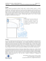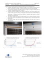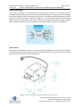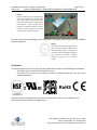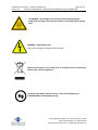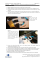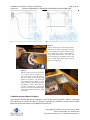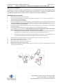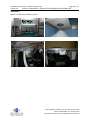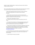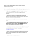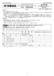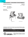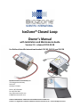
1
IceZone® Closed Loop Owner’s Manual with Installation and Maintenance Guide Version 2.0 - released 2013-03-28 For BioZone Scientific International models CLIZ-05, CLIZ-10, and CLIZ-20 BioZone Scientific International, Inc. 7751 Kingspointe Parkway Suite 124 Orlando, FL 32819 Phone: 407-876-2000 Fax: 407-876-7630 http://biozonescientific.com [email protected] STRICTLY CONFIDENTIAL- ABSOLUTELY NO REPRODUCTION IS PERMITTED IceZone® is a Registered Trademark of BioZone Scientific International, Inc. © 2013 All Rights Reserved. Installation Instructions – IceZone® Closed Loop Page 2 of 14 Version 2.0 STRICTLY CONFIDENTIAL - ABSOLUTELY NO REPRODUCTION IS PERMITTED Table of Contents Purpose ......................................................................................................................................................... 3 Concept ......................................................................................................................................................... 3 BioZone Technology ...................................................................................................................................... 5 Specifications ................................................................................................................................................ 5 Certifications ................................................................................................................................................. 6 Before Installation......................................................................................................................................... 7 Sizing- Which IceZone® Closed Loop to Use ............................................................................................. 7 Requirements ............................................................................................................................................ 7 Selecting the Installation Area .................................................................................................................. 7 Safety ........................................................................................................................................................ 8 Installation Instructions .............................................................................................................................. 10 Troubleshooting Installation Problems ....................................................................................................... 11 Maintenance Instructions ........................................................................................................................... 12 Bulb Replacement Instructions ................................................................................................................... 12 APPENDIX .................................................................................................................................................... 13 7751 Kingspointe Parkway, Suite 124 | Orlando, FL 32819 Phone: 407-876-2000 | Fax: 407-876-7630 http://biozonescientific.com | info@ biozonescientific.com Installation Instructions – IceZone® Closed Loop Page 3 of 14 Version 2.0 STRICTLY CONFIDENTIAL - ABSOLUTELY NO REPRODUCTION IS PERMITTED Purpose BioZone Scientific International’s IceZone® Closed Loop ice machine sanitation system is a device intended to be installed inside commercial ice makers and ice storage bins to keep the internal air and surfaces clean. The IceZone® Closed Loop system utilizes deep ultraviolet light to eliminate bacteria, fungus, and other microbial growth from the inside air and surfaces. The ultraviolet light operates within a reaction chamber inside the IceZone® Closed Loop system and creates Photoplasma gas which is broadcast throughout the host ice maker, inhibiting organic growth in the air and on surfaces throughout the treated area (see Figure 1). Figure 1 Example of IceZone® Closed Loop installed inside of an ice maker. Notice that the tubing is broadcasting Photoplasma throughout the production area and is collecting return air from the storage bin, thus maximizing air circulation within the ice maker. Concept The IceZone® Closed Loop system operates best when the air circulation between the outlet and return intake is maximized within the host equipment. As an example, Photoplasma is distributed to the production area and intake air should be drawn from the ice storage bin area. When correctly installed and properly used and maintained, the IceZone® Closed Loop device keeps ice makers clean, greatly enhancing their functionality and making for cleaner ice. The IceZone® Closed Loop is not intended to be a complete replacement for routine ice maker cleaning, but rather intended to keep ice makers cleaner during the interval in between cleaning cycles and perhaps even extend the cleaning intervals. It has been demonstrated that IceZone® Closed Loop is highly effective and safe to use. IceZone® Closed Loop significantly diminishes the presence of bacteria, yeast, microbes, mold spores, and other organic growths on the surfaces and in the air inside the ice maker (see Figures 2 through 5 on following page). IceZone® Closed Loop is the result of extensive research and sustained product development. Indeed, BioZone Scientific International Inc. has more than a decade of experience in designing and manufacturing products. 7751 Kingspointe Parkway, Suite 124 | Orlando, FL 32819 Phone: 407-876-2000 | Fax: 407-876-7630 http://biozonescientific.com | info@ biozonescientific.com Installation Instructions – IceZone® Closed Loop Page 4 of 14 Version 2.0 STRICTLY CONFIDENTIAL - ABSOLUTELY NO REPRODUCTION IS PERMITTED The best results will be achieved when installed and maintained in the following manner: Purification Photoplasma outlet(s) should be directed near the area where organic growth is known or expected to accumulate. For example, places where air and/or water stagnate. The return line(s) should be positioned near the bin storage area so that circulation within the ice maker is maximized (see Figures 1, 14, and 15). Installation materials included with the IceZone® Closed Loop, such as tubing, fittings, rivets, screws, brackets, clips and/or clamps, are NSF-grade materials and should be installed per NSF specifications. If additional materials are required for installation they should also be NSFapproved for the intended use. The IceZone® Closed Loop should be installed inside of the ice maker mechanical enclosure (control box), and not in the production area or ice storage bin due to unfavorable temperature and humidity. The IceZone® Closed Loop should be operated continuously, even when the ice maker is powered down. Figure 2 - Ice Maker without IceZone® Closed Loop (after 3 Months) Figure 3 - Ice Maker with IceZone® Closed Loop (after 3 Months) Figure 4 - Surface Yeast Counts (through 10 weeks) Figure 5 - Surface Bacteria Counts (through 10 weeks) 7751 Kingspointe Parkway, Suite 124 | Orlando, FL 32819 Phone: 407-876-2000 | Fax: 407-876-7630 http://biozonescientific.com | info@ biozonescientific.com Installation Instructions – IceZone® Closed Loop Page 5 of 14 Version 2.0 STRICTLY CONFIDENTIAL - ABSOLUTELY NO REPRODUCTION IS PERMITTED BioZone Technology As air enters the IceZone®, it is channeled into the air purification chamber. In the chamber, the air is sterilized by the germicidal properties of intense, deep ultraviolet light. In addition, the ultraviolet light reacts with oxygen and water naturally occurring in the air to produce purifying Photoplasma, which is broadcast out of the purification chamber (see Figure 6). The Photoplasma contains reactive oxygen species such as hydroxyl radicals and ozone, which destroy organic compounds including unwanted odors, in addition to bacteria, viruses, fungi, yeast, mold, algae, and other harmful microorganisms. Figure 6 - Deep UV Light creating Photoplasma Specifications The IceZone® Closed Loop is encased in an aluminum body with dimensions of 10.7cm X 8.3cm X 6.5cm. For accessibility to the bulb connectors, the unit should be installed in an area with minimum available dimensions of 16cm X 11.5cm X 6.8cm (see Figure 7). Figure 7 – External envelope of the IceZone® Closed Loop in mm [and inches] 7751 Kingspointe Parkway, Suite 124 | Orlando, FL 32819 Phone: 407-876-2000 | Fax: 407-876-7630 http://biozonescientific.com | info@ biozonescientific.com Installation Instructions – IceZone® Closed Loop Page 6 of 14 Version 2.0 STRICTLY CONFIDENTIAL - ABSOLUTELY NO REPRODUCTION IS PERMITTED Figure 8 IceZone® Closed Loop on its side. Notice the plastic return intake and the metallic outlet tubes. Also depicted are the 12V DC male connector assembly and the ultraviolet light bulb connector. When installing ensure that there is sufficient clearance to access the bulb connector, which will be required should the bulb need to be replaced. The unit has two tubes extending from the front face: 1) the plastic return intake; and 2) the Metallic outlet (see Figure 8). Figure 9 The intake and outlet tubes (see Figure 8) have an internal diameter of 10mm and an external diameter of 12mm. Tubing used to direct and collect Photoplasma throughout the ice maker should have a minimum diameter of 12mm so as to not restrict airflow. Certifications This device complies with Part 15 of the FCC Rules. Operation is subject to the following two conditions: - This device may not cause harmful interference; and - This device must accept any interference received, including interference that may cause undesired operation. RoHS The health aspects associated with the use of this product and its ability to aid in disinfection of environment air have not been investigated by UL. 7751 Kingspointe Parkway, Suite 124 | Orlando, FL 32819 Phone: 407-876-2000 | Fax: 407-876-7630 http://biozonescientific.com | info@ biozonescientific.com Installation Instructions – IceZone® Closed Loop Page 7 of 14 Version 2.0 STRICTLY CONFIDENTIAL - ABSOLUTELY NO REPRODUCTION IS PERMITTED Before Installation Sizing The IceZone® Closed Loop series is comprised of a number of models designed to treat commercial ice makers based on daily production capacity. IZCL-05 is designed for ice makers producing <600 pounds of ice per day. IZCL-10 is designed for ice makers producing between 600 and 1,200 pounds of ice per day. IZCL-20 is for ice makers producing >1,200 pounds of ice per day. Additionally, ice makers operating in challenging environments, such as those located in hot and humid conditions or surrounded by elevated levels of organic compounds, may benefit from a stronger unit than recommended merely by daily ice production. Requirements IceZone® Closed Loop requires a 12VDC, 2.1A power supply for operation. It is recommended that the unit be powered through 90-240VAC, 50/60Hz, available from the ice maker power supply. The unit may also be powered by the ice maker control board (see Figure 14). The unit may also be powered by a external power supply such as a 90-240VAC power wall adapter (with output of 12VDC, 2.1A as required). Tubing, fittings, screws, rivets, brackets, clips and clamps, should they be required for installation, must be NSF-grade materials and should be installed per NSF and UL specifications. Requirements Input Power Current Input Power Voltage Power Source Options Installation Area Tubing Fittings and Clamps Replacement Bulb 2.1 Amps 12VDC Dedicated Power Supply with 12VDC output 12VDC terminal on Control Board 12VDC wall adapter 16cm X 11.5cm X 6.8 cm 1/2" NSF-grade 1/2" NSF-grade IZCL-05: 10-04010 IZCL-10: 10-04050 IZCL-20: 10-04101 Selecting Installation Area This device may not be installed in the ice production area or ice bin, as those areas are classified as food zones by the Food and Drug Administration (FDA). This device may only be installed in a certified electrical enclosure. Examples of such locations are compressor areas of refrigerators, chutes for gas lines, or other electro-mechanical component cabinet or location. In general these are mechanical areas of equipment that are not subject to splash spills, or dirt and debris accumulation. The adequacy of the installation area should be assessed based on the available size, the access to a suitable power source, 7751 Kingspointe Parkway, Suite 124 | Orlando, FL 32819 Phone: 407-876-2000 | Fax: 407-876-7630 http://biozonescientific.com | info@ biozonescientific.com Installation Instructions – IceZone® Closed Loop Page 8 of 14 Version 2.0 STRICTLY CONFIDENTIAL - ABSOLUTELY NO REPRODUCTION IS PERMITTED the availability of a proper mounting location to secure the device with rivets or screws, and the ease of access to change the ultraviolet light bulb as required. The optimal installation location depends on the make and model of the ice machine. The device may be installed and operated in any orientation. It is recommended that the device be secured to the ice maker with a number of conveniently located access holes on the back and side of the device. If you determine that there is not adequate space available inside of the ice maker, please consider using BioZone Scientific’s external IceZone® unit, which can be mounted outside of most commercial ice makers. Safety Instructions WARNING: These procedures should only be performed by a qualified electrician according to national and local electrical codes. Supply power should be turned off during installation or when replacing components or checking connections. Never perform maintenance or cleaning while fixture is energized. Inspect the device for damage that may have occurred during transportation. If the unit has been damaged, do not connect it to the power supply or try to use it otherwise. In the event of damage, immediately contact BioZone Scientific at [email protected]. Check whether the manufacturer of the ice maker has verified the compatibility of the ice maker with IceZone® Closed Loop and has recommended a suitable location for installation of the unit. If so, comply fully with the manufacturer’s instructions. The installation may not be carried out in such a way that it damages electronic components, ice maker components or wiring. Furthermore, installation must not require any modification to or re-positioning of ice maker components. Before installation or maintaining, disconnect the ice maker from the power supply. This appliance is not intended for use by persons (including children) with reduced physical, sensory or mental capabilities, or lack of experience and knowledge, unless they have been given supervision or instruction concerning use of the appliance by a person responsible for their safety. Children are not allowed to use or play with this appliance and should be supervised to ensure this. Use only spare parts approved by BioZone Scientific International. 7751 Kingspointe Parkway, Suite 124 | Orlando, FL 32819 Phone: 407-876-2000 | Fax: 407-876-7630 http://biozonescientific.com | info@ biozonescientific.com Installation Instructions – IceZone® Closed Loop Page 9 of 14 Version 2.0 STRICTLY CONFIDENTIAL - ABSOLUTELY NO REPRODUCTION IS PERMITTED UV WARNING – Eye damage may result from directly viewing the light produced by the lamp in this apparatus. Always turn off lamp before opening cover. WARNING – High voltage inside. Open Circuit Voltage and Voltage to Ground: 600V Dispose of this device or any related parts in accordance with all international, federal, state, and local regulations. The bulb in this product contains mercury. Call or visit LampRecycle at +1-866-666-6859 or www.lamprecycle.org 7751 Kingspointe Parkway, Suite 124 | Orlando, FL 32819 Phone: 407-876-2000 | Fax: 407-876-7630 http://biozonescientific.com | info@ biozonescientific.com Installation Instructions – IceZone® Closed Loop Page 10 of 14 Version 2.0 STRICTLY CONFIDENTIAL - ABSOLUTELY NO REPRODUCTION IS PERMITTED Installation Instructions 1) Before installation, disconnect the ice maker from the power supply 2) Before installation, select the intended installation area and ensure that it is adequately sized 3) Connect the outlet (metallic) and return intake (plastic) tubing to the unit (see Figure 10 - tubing optional) 4) Fasten the IceZone® Closed Loop to the control box area with rivets or screws (see Figure 11 rivets and screws not provided). A mounting bracket may be used to secure the device (see Figure 15- mounting bracket optional) Figure 10 IceZone® Closed Loop with NSF grade tubing, clamps, and fittings installed on the inlet and outlet tubes. Figure 11 IceZone® Closed Loop secured to the ice maker control box with 2 rivets connecting the back of the device to the ice maker. Notice that tubing is installed with clamps and fasteners to broadcast Photoplasma to the production area and draw return air from the ice storage bin. 5) Connect the outlet tubing and route to the desired location, for example, above the evaporator(s) (See Figures 1, 10-13) 6) Secure the outlet tubing, being careful not to cause any folds or creases in the tubing 7) Connect the return intake tubing, for example, to the ice bin storage area (See Figures 1, 10-13) 8) Secure the return intake tubing, being careful not to cause any folds or creases in the tubing 9) Connect the power supply cable to the power supply (see Figure 14) 10) Reconnect the power to the ice maker and turn on 11) The sound of the fan inside the IceZone® Closed Loop will indicate that the unit is operating 7751 Kingspointe Parkway, Suite 124 | Orlando, FL 32819 Phone: 407-876-2000 | Fax: 407-876-7630 http://biozonescientific.com | info@ biozonescientific.com Installation Instructions – IceZone® Closed Loop Page 11 of 14 Version 2.0 STRICTLY CONFIDENTIAL - ABSOLUTELY NO REPRODUCTION IS PERMITTED Figure 12 - Front loaded ice bin Figure 13 - Bottom loaded ice bin Figure 14 IceZone® Closed Loop 12V DC male connector fastened to the female counterpart connector. In the installation pictured the IceZone® Closed Loop is powered by a power supply located on the ice maker control board. The device may also be powered by a dedicated power supply such as a 120V power adapter (with output of 12VDC, 2.1A as required). Figure 15 IceZone® Closed Loop may be secured to an ice maker with the assistance of a mounting bracket or similar apparatus as seen in the image to the left (mounting bracket not provided). The device has been designed to be installed in a wide range of ice maker models from all major manufacturers. Please check with your ice maker manufacturer to ensure that there are no known incompatibilities with the IceZone® Closed Loop and your model of ice maker. Troubleshooting Installation Problems Every IceZone® Closed Loop unit has undergone a strict quality control inspection. However, should the unit malfunction or should you have any questions regarding the installation process please contact BioZone Scientific International at [email protected]. 7751 Kingspointe Parkway, Suite 124 | Orlando, FL 32819 Phone: 407-876-2000 | Fax: 407-876-7630 http://biozonescientific.com | info@ biozonescientific.com Installation Instructions – IceZone® Closed Loop Page 12 of 14 Version 2.0 STRICTLY CONFIDENTIAL - ABSOLUTELY NO REPRODUCTION IS PERMITTED Maintenance Instructions If the device is located in a dusty or smoke-filled area, it is recommended that the bulb be cleaned every three months, as this will significantly extend the life of the bulb. At a minimum, the bulb must be changed every twelve months in order to ensure maximum functionality and efficiency. Bulb Replacement Instructions 1. 2. 3. 4. 5. 6. 7. Disconnect the power supply to the ice machine Access the device by removing the necessary covers and access panels on the ice machine, as instructed in ice machine owner’s manual (not supplied) Disconnect the power supply to the device Disconnect the lampholder from the bulb by gripping the plastic lampholder body and pulling away from the bulb. Do not grip the lampholder by the connecting wires under any circumstances as this is a high voltage hazard. The 4 pins on the “pin-end” of the bulb will be exposed Push the flat end bulb through the end cap of the “flat-end” until approximately 1 inch of the bulb has moved through the “pin-end” end cap Pull the remainder of the bulb from the “pin-end.” Remove either end cap if attached to the bulb Ensure that the bulb has cooled down. When handling the bulb, avoid touching the glass element with exposed fingers as oil and residues from skin can adversely affect the performance of the bulb a. Cleaning the bulb: Clean the bulb with a soft cloth and an appropriate cleansing solvent compatible with quartz glass (such as rubbing alcohol). Cleansing wipes may also be used; Reinsert the bulb b. 8. 9. 10. 11. 12. 13. Changing the bulb: Insert a new bulb (see technical specifications in this manual for correct bulb type). Use only a new BioZone Scientific International bulb (using other bulb will void the warranty) Replace the bulb by inserting the “flat-end” into the appropriate end cap. Insert the “pin-end” end cap Reconnect the lampholder to the “pin-end” of the bulb Reconnect the power supply to the device Replace any access panel removed on the ice machine Reconnect the power supply to the ice machine Dispose of any old bulbs in accordance with all regulations pertaining to hazardous waste disposal (these bulbs contain small traces of mercury) 7751 Kingspointe Parkway, Suite 124 | Orlando, FL 32819 Phone: 407-876-2000 | Fax: 407-876-7630 http://biozonescientific.com | info@ biozonescientific.com Installation Instructions – IceZone® Closed Loop Page 13 of 14 Version 2.0 STRICTLY CONFIDENTIAL - ABSOLUTELY NO REPRODUCTION IS PERMITTED APPENDIX A IceZone® Closed Loop labels: Top (not to scale) Bottom (not to scale) 7751 Kingspointe Parkway, Suite 124 | Orlando, FL 32819 Phone: 407-876-2000 | Fax: 407-876-7630 http://biozonescientific.com | info@ biozonescientific.com Installation Instructions – IceZone® Closed Loop Page 14 of 14 Version 2.0 STRICTLY CONFIDENTIAL - ABSOLUTELY NO REPRODUCTION IS PERMITTED APPENDIX B IceZone® Closed Loop installation photos: Distribution and Return of Photoplasma Slime is not unique to ice makers, as seen in this ice bin Dedicated power supply integrated into installation IceZone® Closed Loop riveted to ice maker frame 7751 Kingspointe Parkway, Suite 124 | Orlando, FL 32819 Phone: 407-876-2000 | Fax: 407-876-7630 http://biozonescientific.com | info@ biozonescientific.com