1
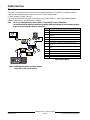
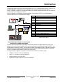
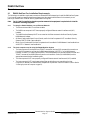
Network Communications System D6600 NetCom
System Guide
D6600 NetCom
Trademarks
Microsoft®, Windows®, Windows NT® are either registered trademarks or trademarks of Microsoft Corporation in the
United States and/or other countries.
D6600 NetCom System Guide
4998122712D
Page 2
© 2004 Bosch Security Systems
D6600 NetCom
Contents
1.0
1.1
1.2
1.3
1.3.1
1.3.2
2.0
2.1
3.0
3.1
3.1.1
3.1.2
3.2
3.3
3.3.1
3.3.2
4.0
4.1
Introduction........................................................................................................................................................................................... 5
Guide Organization ............................................................................................................................................................ 5
Other Literature Referenced ............................................................................................................................................ 5
Documentation Conventions............................................................................................................................................ 6
Type Styles Used in this Guide ....................................................................................................................................... 6
Tips, Important Notes, Cautions and Warnings........................................................................................................... 6
D6600 NetCom Overview .............................................................................................................................................................. 7
D6600 NetCom Pre-Installation Requirements ........................................................................................................ 10
Operation .............................................................................................................................................................................................11
Setting Up the Host Computer..................................................................................................................................... 11
Windows 98/98SE/Me .................................................................................................................................................. 11
Windows 2000/XP/NT................................................................................................................................................... 13
NetCom Failover Solution .............................................................................................................................................. 16
Datagram Type Differences for NetCom .................................................................................................................... 18
Datagram 02 ..................................................................................................................................................................... 18
Datagram 07 ..................................................................................................................................................................... 18
Special D6600 NetCom Applications....................................................................................................................................20
Emulating a Direct Serial Connection Over a LAN Using D6680 Network Adapters ..................................... 20
Figures
Figure 1: D6600 Communications Receiver/Gateway ............................................................................................................ 7
Figure 2: D6600 NetCom System Connection Diagram using C900TTL-E & Any Alarm Panel..................................... 8
Figure 3: D6600 NetCom System Connection Diagram using D9133TTL and Bosch Control Panels........................ 9
Figure 4: D6680 Connection........................................................................................................................................................ 17
Figure 5: Direct Serial LAN Connection Configuration .......................................................................................................... 20
Tables
Table 1: D6600 NetCom System Guide Organization.............................................................................................................. 5
Table 2: Other Literature Referenced............................................................................................................................................ 5
Table 3: Network Adapters Part Numbers.................................................................................................................................... 7
Table 4: Key to Figure 2.................................................................................................................................................................... 8
Table 5: Key to Figure 3 ................................................................................................................................................................... 9
Table 6: Key to Figure 4................................................................................................................................................................. 17
Table 7: NAT Table ......................................................................................................................................................................... 19
D6600 NetCom System Guide
© 2004 Bosch Security Systems
Page 3
4998122712D
D6600 NetCom
Contents
Notes:
D6600 NetCom System Guide
4998122712D
Page 4
© 2004 Bosch Security Systems
D6600 NetCom
Introduction
1.0
Introduction
This system guide covers the installation, operation and programming of the D6600 NetCom Network Communications
System.
References are made to the following control panels: D9412G, D7412G, D7212G, D9412, D9112, D7412, and D7212.
Throughout the remainder of this manual, these control panels will be referred to as “Bosch Control Panels.”
1.1
Guide Organization
This guide is divided into four sections. A summary of each section is detailed in the table below.
Sections
Description
1
Introduction
2
D6600 NetCom Overview – provides an overview of the NetCom system, installation
instructions for the D6600 Receiver/Gateway, optional D6672 Serial Com 1 Expansion Kit
and the host computer.
3
Operation – provides information on setting up the host computer, a solution to NetCom
Failover, and Datagram Type differences.
4
Special D6600 NetCom Applications – using a network to emulate a direct connection
between two COM ports.
Table 1: D6600 NetCom System Guide Organization
1.2
Other Literature Referenced
This manual refers to other documentation with additional information. Table 2 lists the complete part number for
ordering purposes.
Name of document
Part Number
DX4020 Installation Guide
49522
D9133TTL-E Installation Guide
4998122717
C900TTL-E Installation Guide
4998122718
D6680 Network Adapter Installation Guide
4998138732
D6200 Operation and Installation Guide
4998154991
Table 2: Other Literature Referenced
D6600 NetCom System Guide
© 2004 Bosch Security Systems
Page 5
4998122712D
D6600 NetCom
Introduction
1.3
Documentation Conventions
These conventions are intended to call out important features, items, notes, cautions, and warnings that the reader
should be aware of in reading this document.
1.3.1
Type Styles Used in this Guide
To help identify important items in the text, the following type styles are used:
Bold text
Usually indicates selections that you may use while programming your panel. May
also indicate an important fact that you should note.
Bold Italicized text
Denotes notes, cautions and/or warnings.
Italicized text
Refers you to a drawing, table, or other section of this document, or to another
document. Also used to symbolize names for records that you will create.
Courier New
Text
Indicates what may appear on the D5200 Programmer display (if used), command
center/keypad, or internal printer.
[CAPITALIZED
TEXT]
Indicates a specific key to be pressed.
File New
Used to illustrate selecting a menu and sub-menu or command
1.3.2
Tips, Important Notes, Cautions and Warnings
Helpful tips, important notes, cautions and warnings are given for the reader to keep in mind. These appear differently
from the rest of the text:
Important Notes - should be heeded for successful operation and programming. Also tips and shortcuts may be included
here.
Caution - These caution the operator that physical damage to the program and/or equipment may occur.
Warning - These warn of the possibility of physical damage to the operator, program and/or equipment.
0101
0101
0101
These cover notes and clarifications specific to programming the unit.
Programming
Note
0101
0101
0101
These are helpful shortcuts or reminders in programming the unit.
Programming
Tip
D6600 NetCom System Guide
4998122712D
Page 6
© 2004 Bosch Security Systems
D6600 NetCom
Overview
2.0
D6600 NetCom Overview
The D6600 NetCom System supports data network communications.
NetCom allows the D6600 Receiver to connect to Ethernet networks and
process messages both to and from most networks using UDP/IP protocol.
Connection to a data network can be implemented through the use of the
COM4 and/or a COM1 connection from the D6600 Receiver to the D6680
Network Adapter. Reports from alarm control panels via phone lines and/or
Ethernet data networks can be sent to the D6600 Receiver and on to the
central station automation software. Alarm control panels can be monitored
on the network for their status.
Figure 1: D6600 Communications
Receiver/Gateway
The D6600 Software can be upgraded through any network connection. The D6600 can be remotely programmed
through the D6200 Programming/Administration Software.
Bosch Security
Application description
The D6600 has two COM ports on the back
available for network communication connections Systems part
number
– COM4 and the optional COM1. The D6600
requires a separate D6680 Network Adapter for
D6680
D6600 Ethernet Network Adapter
each COM port to be used in order to interface
Table 3: Network Adapters Part Numbers
with an Ethernet network. Most applications will
not initially require that both COM ports be used.
All Alarm Panels to be used with the D6600 NetCom System (from Bosch Security Systems or other manufacturers) must
have an interface similar in function to the Bosch Security Systems D6680 Network Adapter to allow for network
reporting. One method of interfacing an Alarm Panel (Bosch Security Systems or from other manufacturers) to a
network is to use the patented Bosch Security Systems C900TTL-E Dialer Capture Module/network adapter.**
Note: For panel manufacturers other than Bosch Security Systems, refer to the specific panel installation guide for
proper wiring, mounting and installation instructions.
The C900TTL-E module will work with almost any Alarm Panel (Bosch Security Systems or other manufacturer) that
uses a standard digital dialer utilizing one of the following industry standard formats:
•
All Radionics Modem formats
•
DTMF
•
DTMF (where dialer retransmits quickly)
•
BFSK (2300 Hz ACK & 1400 Hz ACK Tone)
•
FBI Superfast DTMF (2300 Hz & 1400 Hz
ACK Tone)
•
Pulse 3/1, 3/1 Checksum (2300 Hz &
1400 Hz ACK Tone)
•
Pulse 4/2 (Long 2300 Hz & Long 1400 Hz
ACK Tone)
•
SIA Bell 103 (110/300 baud, 2016 Hz ACK
Tone)
•
ADT-SIA
•
Telim
•
Robofon
•
SIA Bell 103 (110/300 baud, 2083 Hz ACK
Tone)
•
SIA V.21 (110/300 baud)
•
Seriee DTMF
•
Seriee FSK
D6600 NetCom System Guide
© 2004 Bosch Security Systems
Page 7
4998122712D
D6600 NetCom
Overview
The C900TTL accomplishes this through dial tone and handshake simulations. The C900TTL “intercepts” the Alarm
Panel’s signals and transmits them across the network to a network-enabled D6600.
** Patent numbers 5,134,644, 5,943,394
Figure 2 shows a D6600 NetCom System using a generic control panel, C900TTL-E Dialer Capture Module/network
adapters, D6600 Receiver, and D6680 Network Adapters.
Note: For UL Fire Listed Applications, refer to C900TTL-E Compatibility List (P/N: 4998141056).
For panel manufacturers other than Bosch Security Systems, please consult the specific panel installation guide for
proper wiring, mounting and installation instructions.
1
Item
1
2
3
3
PANEL
7
1
2
3
4
5
6
7
O
F
F
2
TELCO
C
OUT4
O UT3
OUT2
OUT1
IN3
IN2
C
IN1
8
9
10
4
5
6
7
8
9
I-12 V+
8
5
10
12
13
5
4
11
9
10
11
12
13
6
Description
Any manufacturer’s control panel
C900TTL-E
Host PC - D6200 Programming Administrative
Software
Ethernet hub
D6680
D6600 Receiver
Connection - C900TTL-E Ethernet jack to control
panel
Connection - C900TTL-E Ethernet jack to Ethernet
hub
Connection - Host PC Ethernet NIC to Ethernet hub
Connection - Ethernet hub to D6680
Connection - Ethernet hub to D6680
Connection - D6680 to D6600 COM4
Connection - D6680 to D6600 COM1 (optional)
Table 4: Key to Figure 2
Figure 2: D6600 NetCom System Connection Diagram
using C900TTL-E & Any Alarm Panel
D6600 NetCom System Guide
4998122712D
Page 8
© 2004 Bosch Security Systems
D6600 NetCom
Overview
The other type of network interface for Alarm Panels is the D9133TTL-E or DX4020 Network Interface. The D9133TTL/
DX4020 is designed for use with Bosch Control Panels ONLY. No other Alarm Panel will function with the
D9133TTL/DX4020. The D9133TTL/DX4020 and the Bosch Control Panels communicate using the SDI bus rather than
the dialer capture method used by the C900TTL.
Figure 3 is a diagram of a D6600 NetCom System using Bosch Control Panels, D9133TTL-E or DX4020 Network
Interface, D6600 Receiver, and D6680 Network Adapters.
Item
1
2
3
2
1248
7
1
4
5
6
7
8
9
3
4
5
12
13
10
8
11
5
9
10
11
12
13
6
Description
Bosch Control Panels
D9133TTL-E or DX4020 Network Interface Module
Host PC - D6200 Programming Administrative
Software
Ethernet hub
D6680 Network Adapter
D6600 Receiver
Connection - control panel SDI bus to D9133TTL-E/
DX4020 SDI bus
Connection - D9133TTL/DX4020 Ethernet jack to
Ethernet hub
Connection - Ethernet hub to Host PC Ethernet NIC
Connection - Ethernet hub to D6680
Connection - Ethernet hub to D6680
Connection - D6680 to D6600 COM4
Connection - D6680 to D6600 COM1 (optional)
Table 5: Key to Figure 3
Figure 3: D6600 NetCom System Connection Diagram
using D9133TTL and Bosch Control Panels
The Bosch Security Systems D6200 Programming/ Administration Software is a D6600 programming utility that is
designed to work over a network connection. Each network interface device (D6680 Network Adapter, D9133TTL-E or
DX4020 Network Interface, or C900TTL-E Dialer Capture Module) must be added to the ARP (ARP stands for Address
Resolution Protocol and is used to temporarily associate an IP address with a hardware address) table then configured
through a Telnet session before network communications will function.
For the appropriate configuration information for each device see the following installation guides:
•
C900TTL-E Installation Guide (P/N: 4998122718)
•
D9133TTL-E Installation Guide (P/N: 4998122717)
•
DX4020 Installation Guide (P/N: 49522)
•
D6680 Network Adapter Installation Guide (P/N: 4998138732)
D6600 NetCom System Guide
© 2004 Bosch Security Systems
Page 9
4998122712D
D6600 NetCom
Overview
2.1
D6600 NetCom Pre-Installation Requirements
The following pre-installation requirements must be considered BEFORE attempting to install a D6600 NetCom System.
If you have any questions regarding these items, please contact the network administrator for the network you are
planning to interface with or a Bosch Security Systems NetCom Engineer.
Note: For UL Listed Fire Installations, shared on-premises communications equipment is required to be UL Listed for
Information Technology Equipment.
2.1.1
2.1.2
To setup the D6600 NetCom over an Ethernet Network
•
The Ethernet network MUST use Ethernet cables
•
The D6200 host computer MUST have a properly configured Ethernet network interface card (NIC)
installed
•
The D6600 Receiver/Gateway MUST be connected to the Ethernet network via a Bosch Security Systems
D6680 Network Adapter
•
All Alarm Panels, except Bosch Control Panels, used in the NetCom system MUST use a Bosch Security
Systems C900TTL Dialer Capture Module
•
Bosch Control Panels used in the NetCom system should use a Bosch DX4020 Network Interface Module or
a D9133TTL-E Network Interface Module
The host computer used to setup the D6600 NetCom System
•
The host computer will use the ARP and TELNET commands (both are DOS commands that must be run
from the DOS prompt) to configure the D6680 Network Adapter, D9133TTL-E or DX4020 Network
Interface, or C900TTL-E Dialer Capture Module. The D6200 software could be used instead of the ARP and
TELNET commands. See D6200 Software Operation and Installation Guide (P/N: 4998154991) and the
appropriate network device installation guide.
•
The host computer MUST have a properly configured Ethernet network interface card (NIC) installed
•
The host computer MUST have the appropriate Ethernet cable. Be sure to manually set the Host
Computer's IP address to an address that is acceptable to the particular class of the network (refer to Section
3.1 Setting Up the Host Computer on page 11).
D6600 NetCom System Guide
4998122712D
Page 10
© 2004 Bosch Security Systems
D6600 NetCom
Operation
3.0
Operation
3.1
Setting Up the Host Computer
If the computer you intend to use for programming the D6600, D6680, and the alarm panel network adapters is already
a functioning workstation within the network you are planning to utilize, then skip this section!
The host computer is defined as any computer or workstation that is properly configured and connected to the network
you plan on utilizing that will manage/administer the D6600 and other devices. Any existing laptop or desktop computer
on the network can be used. However, for security reasons, it is probably best the computer be set aside and not used as a
regular workstation. This computer will also be the computer on which you will install the D6200 Software. The D6200
Software is used to program and administer the D6600 Receiver and other devices. Separate sections are provided for
setting up the host computer in Windows 98/98SE/Me and in Windows NT/2000/XP
3.1.1
Windows 98/98SE/Me
If the host computer is running Windows 98/98SE/Me and is new to the network the following steps MUST be
performed:
Note: Even though the screen captures are specific to Windows 98, they are similar for Windows 98SE and Me.
1.
In Microsoft® Windows® operating system click on Start
Settings Control Panel.
2.
Once the control panel is open, find and
double-click on the “Network” icon to
launch the Network control panel.
3.
The network dialog box appears with three tabs:
Configuration, Identification and Access Control.
From the Configuration tab, scroll down the Network
components until you get to the TCP\IP protocol for
your Network Interface Card (NIC) which should look
something like this.
Note:
Most NIC cards will be displayed with the label
“Network Adapter.”
Note:
Be sure that you have selected the TCP/IP protocol
for the network adapter, not the adapter itself.
Microsoft Protocol
Icon
4.
Microsoft Adapter Icon
Highlight the protocol icon for TCP/IP bound to your NIC card and click the
"Properties…" button.
D6600 NetCom System Guide
© 2004 Bosch Security Systems
Page 11
4998122712D
D6600 NetCom
Operation
5.
Select the IP address tab, then click the "Specify an IP address" radio
button.
6.
Enter an IP address and subnet mask
for the network you will be setting
up, such as 202.96.168.1.
Note:
If you have any questions regarding the assignment of the IP
address or subnet mask, see the network administrator!
All devices that will be on this network must have the correct subnet mask and
gateway entered.
7.
Some files may have to be copied to the computer.
This may require Microsoft® Windows® operating
system disk for the appropriate version you are using.
8.
After copying the files, the PC may have to be restarted. If so, connect the Host PC's NIC card to the
network (hub) and restart the PC.
9.
After the reboot is completed, you should perform the following check to see if the previous procedures
were correctly entered.
Open a MS-DOS window by selecting Start Programs MS DOS Prompt:
10.
Once the DOS Window appears,
type the command winipcfg
[ENTER].
The IP Configuration window should appear:
Note:
Make sure that the Network Adapter is selected in
the first window, not a PPP adapter. Verify the IP
address, subnet mask, and whatever other
information is listed. (This information should
match the IP and subnet mask you assigned to this
computer in the previous steps).
D6600 NetCom System Guide
4998122712D
Page 12
© 2004 Bosch Security Systems
D6600 NetCom
Operation
If you have chosen to program the D6600’s initial NetCom parameters via the direct null modem serial connection, then
continue on with the following steps. These steps are ONLY necessary if the host computer running the D6200 Software is
connected to the D6600’s COM4 port via a direct NULL modem serial cable!
11.
In Microsoft® Windows® operating system, click on
the Start button and then go to Settings and Control
Panel.
12.
Once the control panel is open, find
and double-click on the “System” icon
to launch the System control panel.
13.
From the Device Manager tab, select Ports. Highlight
the COM port (usually COM1) used to connect the
D6200 Software to the D6600 COM4 port via a direct
connect NULL Cable.
14.
Highlight the port icon and
then click on the
"Properties…" button.
15.
Under the Port
Settings tab,
select 38400
bits per second
baud rate and
then click OK.
3.1.2
Windows 2000/XP/NT
If the host computer is running Windows 2000/XP/NT and is new to the network the following steps MUST be
performed:
Note: Even though the screen captures are specific to Windows 2000, they are similar for Windows XP and NT.
1.
Click on Start Settings Control Panel.
2.
Once the control panel is open, find and
double-click on the “Network and Dial-up
Connections” icon to launch the Network
and Dial-up Connections control panel.
3.
Find and double-click on the “Local Area Connection”
icon.
D6600 NetCom System Guide
© 2004 Bosch Security Systems
Page 13
4998122712D
D6600 NetCom
Operation
4.
Right-click on the icon and
select Properties from the
context menu that appears.
5.
Scroll down in the ”Components checked are used by
this connection:” list and highlight the “Internet Protocol
(TCP/IP)” component.
6.
Highlight the protocol icon for
TCP/IP bound to your NIC card
and click the "Properties…"
button.
7.
Once the dialog box appears, there will be only one tab called “General.”
Click on the option “Use the following IP address:” and
enter an IP address and subnet mask for the network you
will be setting up, such as 202.96.168.1.
Note:
If you have any questions regarding the assignment of
the IP address or subnet mask, see the network
administrator.
All devices that will be on this network must have the correct subnet
mask and gateway entered.
8.
Some files may have to be copied to the computer. This
may require Microsoft® Windows® operating system disk
for the appropriate version you are using.
9.
After copying the files, the PC may have to be restarted. If so, connect the Host PC's NIC card to the
network (hub) and restart the PC.
D6600 NetCom System Guide
4998122712D
Page 14
© 2004 Bosch Security Systems
D6600 NetCom
Operation
10.
After the reboot is completed, you should perform the following check to see if the previous procedures
were correctly entered.
11.
Open the Run dialog box by selecting Start Programs
Accessories Command Prompt.
A command prompt window appears.
Type ipconfig and press [ENTER].
The IP configuration for the PC is returned. The
following information is displayed:
Connection-specific DNS Suffix
IP Address
Subnet Mask
Default Gateway
12.
Note:
Verify the IP address, subnet mask, and whatever other information is listed. (This information should
match the IP and subnet mask you assigned to this computer in the previous steps).
If you have chosen to program the D6600’s initial NetCom parameters via the direct null modem serial connection, then
continue on with the following steps. These steps are ONLY necessary if the host computer running the D6200 Software is
connected to the D6600’s COM4 port via a direct NULL modem serial cable!
13.
Click Start
Settings
Control Panel
to open the
Control Panel.
14.
Once the Control Panel window opens, double-click on the
System icon.
15.
The System
Properties
window opens
to show a row
of five tabs.
16.
Click on the Hardware tab.
17.
Click the Device Manager button.
D6600 NetCom System Guide
© 2004 Bosch Security Systems
Page 15
4998122712D
D6600 NetCom
Operation
3.2
18.
A hardware tree
appears showing all
the devices connected
to the PC in the top
level.
19.
Click on the small plus sign (
reveal the individual ports
20.
Highlight the Communications Port (COM1) used to connect
the D6200 Software to the D6600 COM4 port via a direct connect
NULL Cable.
21.
Right click and select Properties from the menu that appears.
22.
The Communications Port (COM1) window appears with four
tabs across the top.
23.
Select the Port Settings tab
24.
Select 38400 bits per second
baud rate from the Bits per
second: drop down menu
and then click OK.
) next to Ports (COM & LPT) to
NetCom Failover Solution
An installed NetCom System should consist of at least 2-D6600s and 2-D6680s to allow for a redundant backup to the
first system in the event of a system #1 failure. To allow for a redundant backup of the D6680, the programmed IP
Address of D6680 #1 has to be programmed for into D6680 #2. This would allow for a change over from D6680 #1 to
D6680 #2 and only one of the D6680s connected to the network at one time. To most this would seem like a simple
solution, but it is much more complex that it appears. In a network environment the MAC address plays a crucial role in
delivery of the data to the D6680. By simply switching from D6680 #1 to D6680 #2, there would be no data delivered to
D6680 #2 immediately after switching. This section is not to explain why this happens, rather how to overcome this.
Software version 5.5C or greater must be installed in the D6680 for the Alternate MAC Address function.
In Figure 4, each of the D6680s are programmed with the same IP Address, but only one is connected to the network at
the same time by using an AB Switch as shown. This switch could also be a larger switch which also changes the phone
lines from one 6600 to the other or any other type of switch that the location may be using as long as it switched the
Network connection from one 6680 to the other.
D6600 NetCom System Guide
4998122712D
Page 16
© 2004 Bosch Security Systems
D6600 NetCom
Operation
COM1
COM4
COM1
1
COM4
2
7
7
D6680
Callout
1
2
3
4
5
6
7
D6680
4
3
A B C
Description
D6600 Receiver #1
D6600 Receiver #2
D6680 #1
D6680 #2
A/B Network switch
Network switch
Null modem cable
Table 6: Key to Figure 4
5
6
Figure 4: D6680 Connection
In Figure 4, another programming parameter that will need to be done is what we will refer to as Alternate MAC Address.
The Alternate MAC Address function will allow a switch between the D6680s to happen without the network knowing
that anything has changed. The programming of the D6680s should be as follows:
1. Program D6680 #1 as described in the D6680 Network Adapter Installation Guide (P/N: 4998138732) for all
parameters including Channel 1 using port 7700 as the default port number (this port can be different as described
in the D6680 Network Adapter Installation Guide). Program Channel 2 with the same settings that are in Channel 1
except the port number would be 7701 (or any number (2000 to 10000) that is different than Channel 1 in your
setup). If using encryption, perform the setup as in the D6680 Network Adapter Installation Guide. Save the settings
and exit.
2. Write down the MAC Address of D6680 #1. This will be needed during the setup of D6680 #2.
3. Program D6680 #2 with the same settings that you entered into D6680 #1, do not save and exit but continue to the
next step..
Both D6680s cannot be connected to the network at the same time.
4.
After completing these settings, there are two additional settings that need to be done.
•
Under Expert Settings (Menu Item 5), there is a prompt for Alternate MAC Address. At this prompt enter
the MAC Address of D6680 #1.
•
5.
6.
Under Security Settings (Menu Item 6), change the prompt for Alternate MAC to a Y so that the D6680
will use the Alternate MAC Address which was programmed in Menu Item 5. Save the settings and exit.
Connect the cabling as shown in Figure 4. Be sure that there is a switch box for the network cable connection.
In the D6200 software, two receivers will need to be added as follows:
•
Add the first receiver calling it Primary Receiver with the Receiver IP Address and Receiver Port number for
Channel 1 of the D6680s.
•
7.
Add the second receiver calling it Backup Receiver with the Receiver IP Address and Receiver Port number
for Channel 2 of the D6680s.
In the D6200 software, you would select the Primary receiver when programming changes are needed. After all
program settings have been sent to the Primary Receiver, change the receiver in the Connection settings to Backup
Receiver and send the same parameters to the backup receiver.
D6600 NetCom System Guide
© 2004 Bosch Security Systems
Page 17
4998122712D
D6600 NetCom
Operation
3.3
Datagram Type Differences for NetCom
Software version 5.5C or greater must be installed in the network device (C900TTL-E, D9133TTL-E, or D6680) for the
Datagram Type function.
Software version 1.5D or greater must be installed in the DX4020.
3.3.1
Datagram 02
This datagram is only supported on the COBOX-FL version of the D6680.
This datagram type is only used in the D6680. This datagram uses the IP Address as well as the Port Number to identify
and ACK packets from the receiver to the field devices which allows multiple devices to be installed behind a single
outgoing IP Address. This datagram type requires that CPU version 01.02.01 or higher needs to be installed and in the
receiver parameter 6.8.6 MUST be programmed for a 1.
To use this datagram type, program in the following order:
1. Be sure that D6200 version 1.20 or higher is installed.
2. Be sure that the D6600 CPU version 01.02.01 is loaded in the receiver.
3. With the D6200 software, select ‘Read/Manage Network Configuration from Receiver’.
4. Click on the ‘6.8 Global Parameters’ tab.
5. Change the selection of 6.8.6 6600 Datagram Type to a 1.
6. Send the changes to the receiver and close the window.
7. Select NetCom - Network Utilities – Network Device Setup and click on the Telnet to Device tab.
8. Type or find the IP Address of the D6680 in the list and Telnet to the D6680.
9. After establishing the Telnet session, select the channel(s) that you are using by pressing 1 or 2 and pressing Enter.
10. Press Enter until at the selection of Datagram and type 02 and press Enter. If both channels are being used, be sure
that both channels are changed.
11. Save the settings and exit the setup of the D6680.
3.3.2
Datagram 07
This datagram is only supported on the E2-RAD version of the Network Interface Modules (NIMs).
This datagram type is only used in the NIM of the network device (C900TTL-E, D9133TTL-E, or DX4020). The
datagram type allows the Source and Destination ports to be set independently. This use of a different source port allows
NAT (Network Address Translation) tables of routers or firewalls to direct packets to the correct NIM of the field device.
The way that a NAT table works is explained below:
To use this datagram type, program in the following order:
1. Telnet to the NIM of the field device as is described in the appropriate network device (C900TTL-E, D9133TTL-E, or
DX4020) installation guide.
2. Select channel 1 of the NIM.
3. At the Port Number selection, enter a source port that is not being used by another NIM on the same network (such
as 7701, 7702, 7703, etc.). Keeping a list of the NetCom modules on a particular network along with the source ports
of those modules will ensure that duplicate source ports are not used.
4. At the Datagram selection, enter 07 and press Enter.
5. At the Remote Port selection, enter the port number that is used in the D6680 for the D6600.
6. Save the settings and exit the setup of the NIM.
Outgoing packets from a network over a single IP Address go through a router or firewall software that uses NAT tables
to keep track of which packets come from which internal IP Addresses. The NAT table insures that the returning packets
for a device are forwarded back to the device that sent out the first packet. An example of this is multiple PCs on a
network connecting to the internet through a single IP Address from an ISP. By using the same idea, NetCom devices
can perform the same function.
D6600 NetCom System Guide
4998122712D
Page 18
© 2004 Bosch Security Systems
D6600 NetCom
Operation
Internal IP Address
Source Port
Table 7 shows an example of what the NAT table
remembers when packets are sent out to a destination. An 192.168.1.11
7700
outgoing packet is sent to an IP Address with both a Source
192.168.1.12
7701
and Destination port in that packet. The Destination port
192.168.1.13
7702
is the port number that the device is listening for data.
After it receives the data it will process it and send a packet
Table 7: NAT Table
back to the IP Address that sent the data using a
Destination port that is the same as the Source port that
sent the data.
When the data is returned to the router or firewall software, it directs the returning packet to the correct Internal IP
Address based on the NAT table
D6600 NetCom System Guide
© 2004 Bosch Security Systems
Page 19
4998122712D
4.0
Special D6600 NetCom Applications
The following are special applications that have been requested by Bosch Security Systems dealers. They are included here
to assist you should you have the same requirements. If you have any questions, please feel free to contact Technical
Support at (888) 886-6189.
4.1
Emulating a Direct Serial Connection Over a LAN Using D6680 Network Adapters
In some applications it may be required that a direct serial connection be emulated over the network. One application
that would require this is where the D6600 Receiver is located on another part of the network from the Automation
System. We can take the COM3 automation output from the D6600 and using two D6680’s we can pipe a direct serial
connection between the D6600 and the Automation System. This is true serial cable emulation over the network (see
Figure 5).
D6600
Receiver
COM3
D6680
#1
Ethernet
192.158.001.017
D6680
#2
RS232
Automation
System
192.168.001.016
Figure 5: Direct Serial LAN Connection Configuration
The commands necessary for this configuration to automatically establish this connection are as follows. Note the
reference to the D6680’s by their number (#1 or #2). You will also need to insure that the port parameters such as speed,
number of bits, flow control etc. are correct on the D6680 for the serial device that they are connected to.
D6680 #1:
D6680 #2:
*** basic parameters
Hardware: Ethernet TPI
IP address: 192.168.001.017, no gateway set
*** basic parameters
Hardware: Ethernet TPI
IP address: 192.168.001.016, no gateway set
******* Channel 1 *******
Baudrate 9600, I/F Mode 4C, Flow 00
Port 7700
Remote IP Adr: 192.168.001.016, Port 7700
Connect Mode: C0
******* Channel 1 *******
Baudrate 09600, I/F Mode 4C, Flow 00
Port 7700
Remote IP Adr: 192.168.001.017, Port 7700
Connect Mode: C0
For more information, refer to the D6680 Network Adapter Installation Guide (P/N: 4998138732).
© 2004 Bosch Security Systems
130 Perinton Parkway, Fairport, NY 14450-9199 USA
Customer Service: (800) 289-0096; Technical Support: (888) 886-6189
4998122712D
System Guide
6/04
D6600 NetCom
Page 20 of 20