1
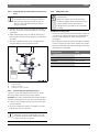
DHW, Domestic Hot Water Cylinder
BSS 2C-250-21-2 / BSS 2C-250-26-2
BSS 2C-340-21-2 / BSS 2C-340-26-2
BSS 2C-400-21-3 / BSS 2C-400-26-3
BSS 2C-250-2E / BSS 2C-340-2E
BSS 2C-400-3E
6 720 618 429 (2011/01) AU/NZ
Installation and maintenance instructions for contractors
This solar hot water system must be installed in accordance with the manufacturer's installation
instructions, AS5601, AS3500.4. AS3000 wiring regulations (in New Zealand NZBC G12) and all
Local Building, Water and Gas fitting regulations.
To be installed and serviced only by an authorised person
The “authorised installing person” is responsible for:
1. Correct commissioning of this system.
2. Ensure units performs to the specifications stated on the rating label.
3. Demonstrate operation of the system to the customer before leaving.
4. Hand these instructions to customer.
Failure to install this system in accordance with these installation instructions may void warranty.
Note: These instructions are subject to change, due to continuous product improvement.
2 | Table of Contents
AU/NZ
Table of Contents
1
1.1
1.2
Key to symbols and safety instructions
Explanation of symbols
Safety instructions
3
3
3
6.3
6.4
6.5
6.6
Adjusting the flow rate
Fitting the casing shell
After commissioning
User information from the system installer
25
25
26
26
2
2.1
2.2
2.2.1
5
5
5
7
7.1
7.2
Shutting down
Shutting down the DHW cylinder
Shutting down the DHW cylinder if there is
a risk of frost
27
27
2.3
2.4
2.5
2.6
Product information
Standard delivery
Product description
Main components of the solar circuit pump
and safety assemblies
Correct use
Tools, materials and auxiliary equipment
Dimensions and connections
Specification
8
Environmental protection/disposal
28
Regulations
10
Maintenance
Checking the magnesium anodes
Restarting the DHW cylinder after
maintenance
29
29
3
9
9.1
9.2
4
Shipping
11
Warranty details
31
5
5.1
5.1.1
5.1.2
5.2
5.3
5.3.1
5.3.2
5.3.3
Installation
Location
Requirements for installation location
Positioning the DHW cylinder
Removing the casing shell
Water connections
Connection options
Connecting the solar thermal system
Pipe Connections to Gas Booster or Electric
Booster and DHW Network
Fitting the PTR valve
Checking for leaks
Installing the temperature sensors
Installing the DHW temperature sensor
Collector temperature sensor
Electrical connections
Making the electrical connections to the
SolaStat-Eco solar controller
Connect the electric heating element
electrically (for electric boost ONLY)
Gas Booster Installation
12
12
12
12
13
14
14
14
Commissioning the system
Commissioning the DHW cylinder
Purging and filling
Purging the pipework
Carrying out pressure test with water
Replacing water with heat transfer medium
Verifying that the solar thermal system is
free of air
Determining the operating pressure
Filling with water
21
21
21
21
22
23
5.3.4
5.3.5
5.4
5.4.1
5.4.2
5.5
5.5.1
5.5.2
5.5.3
6
6.1
6.2
6.2.1
6.2.2
6.2.3
6.2.4
6.2.5
6.2.6
6 720 618 429 (2011/01)
6
7
7
8
9
16
17
17
18
18
18
19
19
19
20
24
24
24
10
27
30
AU/NZ
Key to symbols and safety instructions | 3
1
Key to symbols and safety instructions
1.1
Explanation of symbols
Warnings
1.2
Safety instructions
Installation, conversion
Warnings in this document are framed and
identified by a warning triangle printed
against a grey background.
If there is a danger due to electricity, the
exclamation mark in the warning triangle is
replaced by a lightning symbol.
Signal words at the start of a warning indicate the type
and seriousness of the ensuing risk if measures to
prevent the risk are not taken.
• NOTICE indicates that material losses may occur.
B Risk of fire from soldering and welding!
Take appropriate protective measures when soldering
and welding as the thermal insulation is flammable,
for example cover the thermal insulation.
B Ensure that the DHW cylinder is installed or converted
by an authorised contractor only.
B Use installation materials that are sufficiently heatresistant.
Function
B Observe these installation and maintenance
instructions to ensure trouble-free operation.
• CAUTION indicates that minor to medium injury may
occur.
B Never close the blow-off line of the PTR valve. During
heating, water may be ejected for safety reasons.
• WARNING indicates possible severe personal injury.
Danger from electrical currents
• DANGER indicates a risk to life.
B Ensure that any electrical work is only carried out by
an approved electrician.
Important information
Important information where there is no risk
to people or property is indicated with the
adjacent symbol. It is bordered by lines
above and below the text.
Additional symbols
Symbol
Meaning
B
Action step
Æ
Cross-reference to other parts of this
document or to other documents
•
List/list entry
B Before removing the casing shell, isolate all poles of
the solar thermal system and secure against
unintentional reconnection.
Risk of scalding at the hot water draw-off points
B When the DHW cylinder is in operation, temperatures
in excess of 50 °C can occur. To limit the draw-off
temperature, fit a thermal DHW mixer.
B This heater supplies water at a temperature
exceeding 50 °C. A tempering valve must be fitted
between the water heater and the outlets in
bathrooms and ensuites to comply with the water
temperature requirements of AS 3500.4.
Tab. 1
6 720 618 429 (2011/01)
4 | Key to symbols and safety instructions
Using the electric heating element (BSS 2C-250-2E /
BSS 2C-340-2E / BSS 2C-400-3E)
B Ensure that any electrical work is only carried out by
an approved electrician.
B Before starting electrical work on the solar thermal
system, isolate all poles of the system and secure
against unintentional reconnection.
B Ensure the system has been isolated from the supply.
For operation with the electric heating element, observe
the following points in order to maintain the corrosion
protection and to adhere to the guidelines for electrical
safety:
B Do not operate electrically heated DHW cylinders with
an inert anode.
B Use metal connection fittings in DHW heating
systemswith plastic lines.
B Use original electric heating element only.
B When installation of the cylinder is complete, inspect
the earth conductor (including metal connection
fittings).
Maintenance
B Customer recommendation:
Arrange a maintenance and inspection contract with
an approved contractor. Have the DHW cylinder
inspected and, if required, serviced annually.
B Only original spare parts must be used.
6 720 618 429 (2011/01)
AU/NZ
AU/NZ
Product information | 5
2
Product information
2.1
Standard delivery
The DHW cylinder is delivered fully assembled with the
solar circuit pump attached.
The following parts of the standard delivery are packed
separately:
• SolaStat-Eco solar controller
• Pressure-temperature relief (PTR) valve
• Foot bolts
• Technical documentation
2.2
Product description
The BSS 2C-250/340-2E, BSS 2C-400-3E DHW cylinder is
equipped with an electric heating element.
The BSS 2C-250/340-21-2, BSS 2C-250/340-26-2,
BSS 2C-400-21/26-3 DHW cylinder operates with a gas
fired external water heater booster.
The main components of the DHW cylinder are:
• Storage cylinder with corrosion protection
The cathodic corrosion protection comprises the
hygienic thermal glaze and two magnesium anodes.
• Bare-tube heat exchanger
The bare-tube heat exchanger transfers the energy
from the solar circuit to the DHW inside the storage
cylinder. The DHW is heated evenly.
• Thermal insulation
The thermal insulation, made from CFC-free hard
polyurethane foam, is directly applied to the storage
cylinder and insulates against heat loss.
Fig. 1
1
2
3
4
5
6
7
Sectional view of DHW cylinder
Foot bolts
Bare-tube heat exchanger (solar thermal system)
Thermal insulation
Thermal glaze
Storage cylinder
Magnesium anodes
Sensor well
• Sensor well with DHW temperature sensor
The DHW temperature sensor supplies temperature
information to the control.
NOTICE:
This appliance must not be used as a pool
heater.
6 720 618 429 (2011/01)
6 | Product information
• Solar circuit pump assembly
The solar circuit pump assembly supplies the solar
circuit.
• Casing shell
AU/NZ
2.2.1
Main components of the solar circuit pump and
safety assemblies
The solar circuit pump and safety assemblies (Æ Fig. 3)
are pre-assembled on the DHW cylinder.
• Casing lid
• Electric heating element (for SM250/340/400 E BO
only)
In addition to the collectors, the electric heating
element is an additional heat source for DHW heating.
• Solar controller (not shown here)
The SolaStat-Eco solar controller switches the solar
circuit pump on and off subject to the temperature
differential between the collector sensor and the
DHW temperature sensor.
6 720 618 426-03.1RS
Fig. 3
1
2
3
4
5
6
Fig. 2
1
2
3
4
5
6
7
8
DHW cylinder
Casing shell
Expansion vessel
Casing lid
PTR valve
Electric heating element (for SM electric Boost only)
Thermal insulation
Solar circuit pump assembly
Safety assembly
6 720 618 429 (2011/01)
Solar circuit pump and safety assemblies
Pressure gauge in the safety assembly
Ball valve with thermometer (blue = return) and integrated
gravity brake (position 0° = normal running, 45° = gravity
brake bypassed)
Solar circuit pump
Flow limiter
Drain & fill valve (DFV)
Flow rate indicator
AU/NZ
2.3
Product information | 7
Correct use
The DHW cylinder is designed for heating and storing
domestic hot water. Please observe all DHW regulations,
guidelines and standards for your country.
Operate the DHW cylinder via the solar circuit using heat
transfer medium only and in sealed unvented systems
only.
The solar pump station may only be used for the
operation of solar thermal systems in conjunction with
suitable controllers from the same manufacturer.
The solar pump station is exclusively intended for
operating solar thermal systems filled with propylene
glycol/water mixtures. The use of any other heat transfer
medium is not permitted.
Any other application will be considered incorrect use.
No liability for any losses resulting from such use is
accepted.
2.4
Tools, materials and auxiliary
equipment
You need standard tools for the installation and
maintenance of the DHW cylinder, as used in gas and
water installations.
In addition, a hand trolley with a strap may also be
useful.
6 720 618 429 (2011/01)
8 | Product information
2.5
Fig. 4
AU/NZ
Dimensions and connections
Dimensions and connections
AW
EH
EK
EL
M
DHW outlet
Connection flange for electric heating element
Cold water inlet
Drain
Test point for DHW temperature sensor of the solar thermal
system
PTR Pressure-temperature relief valve
RS
Cylinder return (solar thermal system)
VS
Cylinder flow (solar thermal system)
Dimension SM250 xxx
SM340 xxx
SM400 xxx
D
600
700
700
H
1517
1430
1650
H1
110
135
135
H2
585
610
610
H3
680
705
705
H4
1370
1275
1495
H5
300
325
325
H6
780
775
905
Tab. 2
Dimensions for Fig. 4
6 720 618 429 (2011/01)
AU/NZ
2.6
Product information | 9
Specification
DHW cylinder
Cylinder capacity
Standby capacity for electric heating element
Diameter D
Depth
Height H 1)
Minimum ceiling height of installation room2)
DHW outlet (AW) thread
Cylinder flow (solar thermal system; VS) and cylinder return
(solar thermal system; RS) thread
Cold water inlet (EK) and drain (EL) thread
PTR valve connection thread
Connection flange for electric heating element (EH) thread
Dry weight3)
Bare-tube heat exchanger (solar thermal system):
Solar heat exchanger capacity
Solar heat exchanger surface area
Installation components:
Permissible temperature:
• Flow
• Return (pump)
Safety valve response pressure
Safety valve
Mains voltage for pump
Maximum power consumption of pump
Output of electric heating element (Grimwood) thread
Flow and return connections (locking ring fittings) thread
Maximum permissible values:
DHW temperature
DHW operating pressure
Connection for flat-plate collectors:
Number of flat-plate collectors
Straight pipe length; Ø 15 mm (DN12)
Tab. 3
l
l
mm
mm
mm
mm
mm
mm
SM250 xxx
250
120
600
800
1517
2050
mm
mm
mm
kg
137
l
m2
5.2
1.2
SM340 xxx
340
155
700
900
1430
1950
20
15
SM400 xxx
400
180
700
900
1650
2150
20
15
64 x 64 (M8 to 46 x 46)
197
213
7
1.6
7
1.6
°C
130
°C
kPa
A
Watt
mm
110
300
DN 15, 15 mm connection
230 V AC, 50 - 60 Hz
0.25
3600
15
°C
kPa
95
850
2
2
m
3
7
Dimensions and specification
1) Incl. casing lid, excl. foot bolt.
2) Minimum ceiling height of the installation room required for the replacement of the magnesium anode.
3) Excl. contents, incl. packaging.
6 720 618 429 (2011/01)
10 | Regulations
3
AU/NZ
Regulations
Different or supplementary regulations (e.g.
mains connection requirements) may apply
subject to the installation location (e.g. in
different countries or regions).
B Observe the country-specific or regional
regulations, guidelines and standards
(e.g. those of the power supply utility)
when installing and operating the DHW
cylinder and the electric heating element.
All installations must be carried out in accordance with
AS/NZS3500.4, NZS5261, AS/NZS3000 and all local
building, plumbing and electrical regulations.
CAUTION:
For sanitary fixtures used primarily for the
purpose of personal hygiene that a
temperature control device be fitted (such
as a tempering valve) as per AS3498 must
be used.
AS 2239
Galvanic (sacrificial) anodes for cathodic protection
AS 2712
Solar and heat pump water heaters- Design and construction
AS 3498
Authorization requirements for plumbing products- Water heaters and hot-water storage tanks
AS 3500.4
Plumbing and drainage Part 4: Heated water services
AS 3688
Metallic connections and end fittings
AS 4020
Testing of products for use in contact with drinking water
AS 4692.1
Electric water heaters Energy consumption, performance and general requirements
AS/NZS
60335.2.21
Household and similar electrical appliances-Safety
Part 2.21: Particular requirements for storage water heaters
Tab. 4
Standards
6 720 618 429 (2011/01)
AU/NZ
4
Shipping | 11
Shipping
WARNING: Risk of injury from carrying
heavy loads and inadequately securing
loads for transport.
B Use suitable means of transportation,
e.g. a hand trolley with strap.
B Transport the DHW cylinder to the installation
location.
B Remove packaging.
B Remove wood screws [1] from locking plate [2].
B Unscrew and remove locking plate.
B Secure the DHW cylinder against
slipping.
Where possible, transport the DHW cylinder
fully packed to the installation location. This
ensures protection during handling.
If you are transporting the DHW cylinder
unpacked, use a transport net. Protect the
connections against damage.
B Position the hand trolley at the back of the packed
DHW cylinder.
B Secure the DHW cylinder to the means of
transportation with a strap.
Fig. 6
1
2
Fig. 5
Removing the locking plates
Wood screws
Locking plate
Securing the DHW cylinder for transport
6 720 618 429 (2011/01)
12 | Installation
5
AU/NZ
Installation
The DHW cylinder is delivered as a fully assembled unit.
B Check that the delivered package(s) are complete and
in perfect condition (Æ Chapter 2.1, page 5).
B Dispose of packaging in an environmentally
responsible manner.
5.1
Location
5.1.1
Requirements for installation location
The DHW cylinder may be installed either indoors or
outdoors.
NOTICE: System damage through
inadequate load-bearing capacity of the
supporting surface or unsuitable substrate.
B Ensure that the installation area offers
sufficient load-bearing capacity.
NOTICE: System damage due to corrosion!
B Install the DHW cylinder in dry condition.
B Only install this DHW cylinder in sealed
unvented systems.
B Never use open vented expansion
vessels.
At least 500 mm clearance above and in
front of the DHW cylinder is required for the
replacement of the magnesium anode and
the electric heating element (during
maintenance).
Fig. 7
1
2
Minimum wall clearances (in mm)
Connection on the left-hand side
Connection on the right-hand side
5.1.2
Positioning the DHW cylinder
B Lift the DHW cylinder from the pallet and position it
on a level floor that has adequate load-bearing
capacity.
B Tilt DHW cylinder slowly onto the pallet [1].
B Remove hexagon bolts [2].
B Pre-assemble foot bolts [3] to approx. 20 mm.
B Stand the DHW cylinder upright at the installation
location and level it using the foot bolts.
B To comply with NZBC G12 Building code, please
install cylinders with seismic straps as shown below:
B Maintain the minimum height and minimum
wall clearances in the installation room.
(Æ Tab. 3, page 9 and Fig. 7).
If the DHW cylinder is connected on the lefthand side, maintain a minimum wall
clearance (A) of 500 mm.
Fig. 8
6 720 618 429 (2011/01)
Seismic Restraint of Storage Water Heaters
90 - 360 litres
AU/NZ
Installation | 13
B It is a requirement of the National Plumbing Code AS/
NZS3500.4.2 that new water heaters be installed in a
safe tray where in the event of a leak, property may be
damaged (ie internal installations). Installation of
such trays must comply with Clause 4.4 and SubClauses 1 to 5 of the above mentioned Code.
Fig. 9
1
2
3
5.2
Removing the casing shell
B Remove four push rivets [1] from the casing shell.
B Lift the casing shell [2] up and off.
B Disconnect the earth wire [3] from earth conductor
connection.
Fitting the foot bolts
Suitable surface (e.g. pallet)
Hexagon bolts
Foot bolts
WARNING: If the hot water system is not
used for two weeks or more, a quantity of
highly flammable hydrogen gas may
accumulate in the water heater. To dissipate
this gas safely, it is recommended that a hot
tap be turned on for several minutes or until
the discharge of gas ceases. Use a sink, basin
or bath outlet, but not a dishwasher, clothes
washer or other appliance. During this
procedure, there must be no smoking, open
flame or any electrical appliance operating
nearby. If the hydrogen is discharged
through the tap, it will probably make an
unusual sound as with escaping air.
Fig. 10 Removing the casing shell
1
2
3
Push rivet
Casing shell
Earth wire
6 720 618 429 (2011/01)
14 | Installation
5.3
Water connections
DANGER: Risk of fire through soldering and
welding!
AU/NZ
5.3.1
Connection options
Hydraulic connections on the DHW cylinder can be
routed out either to the left [A] or the right [B] through
the casing shell.
B Take appropriate protective measures
when soldering and welding as the
thermal insulation is flammable, for
example cover the thermal insulation.
LEFT
RIGHT
B Check thermal insulation after
completion for perfect condition.
WARNING: Risk to health through
contaminated water!
Work carried out without due care for
cleanliness contaminates the potable
water.
B The water heater is not recommended
for connection to a bore water supply.
Many such sources contain contaminants
harmful to the components of the solar
system. If the system is connected to bore
supply against our recommendation,
warranty does not apply. See details on
warranty page
Fig. 11 Right-hand and left-hand versions
B Install and equip the DHW cylinder
hygienically in accordance with national
standards and guidelines.
B For more information regarding connection of the
solar collectors, please see the solar collectors IM.
B Flush the DHW cylinder and pipework
thoroughly with potable water after
installation.
NOTICE: Damage through incorrect
connectors!
B Use installation material that is heatresistant to 150 °C.
B Use metal connection fittings in DHW
heating systems with plastic lines.
B When using an electric heating element:
When installation of the DHW cylinder is
complete, inspect the earth conductor
(including metal connection fittings).
6 720 618 429 (2011/01)
5.3.2
Connecting the solar thermal system
B Connect collectors at the DHW cylinder's flow and
return using piping.
AU/NZ
Installation | 15
B To prevent air locks: route the pipes from the cylinder
to the collector field on a rising incline.
Connecting piping
B Copper pipes for solar thermal systems should always
be soldered with brazing or silver solder (i.e. not soft
solder).
B Compression fittings or push-fit fittings can be used
instead of soldering if they are glycol and heatresistant (150 °C).
We recommend carrying out a pipe network
analysis to design the piping. Basic design
estimates can be made using Tab. 5.
B If there are many additional points of
resistance (bends, valves), you may need
to select a pipe with a larger diameter.
NOTICE: Risk of system damage due to
overheated components!
B Design the straight pipe length to be at
least 7 m from the DHW cylinder to the
flat-plate collectors.
Fig. 12 System scheme
1
2
3
Solar controller (SolaStat-Eco)
Collectors
DHW cylinder
Set the expansion valve's pre-charge pressure
The pre-charge pressure of the expansion
vessel is given by the static system head
plus 40 kPa (1 metre difference in height
equals 10 kPa).
Straight pipe length
1 - 3 collectors
up to 15 m
15 mm copper pipe
Tab. 5
Pipe sizing
Earthing pipes
B Fit one earthing clip each to the flow and return pipe.
B Connect the earthing clips via an earth cable type
NYM with at least 6 mm2 to the equipotential busbar
of the building.
B Set pre-charge pressure to at least
120 kPa.
B If the calculated pre-charge pressure is higher or
lower than the factory-set pre-charge pressure,
correct the pre-charge pressure accordingly.
B To make use of the maximum possible volume, set the
pre-charge pressure prior to pressurising the heat
transfer medium side.
6 720 618 429 (2011/01)
16 | Installation
AU/NZ
Laying pipes with an automatic air vent valve on the
roof (available as accessory)
5.3.3
B Pipes to the air vent valve should follow a rising
gradient.
Any downward change of direction requires an
additional automatic air vent valve (temperatureresistant to 150 °C.
B Use only threaded fittings, with shut-off valves if
required, to connect lines to the cylinder. Connect
cylinder connections to piping on site.
Pipe Connections to Gas Booster or Electric
Booster and DHW Network
B Fit the on-site drain at the lower cylinder connection.
WARNING: Scalding from hot water!
If the system is filled without a filling
station, an automatic air vent valve is
required.
The DHW temperature can be as high as
90 °C in solar mode.
B To limit the draw-off temperature to a
maximum of 50 °C, fit a tempering valve
(accessory) in the DHW line (Æ Fig. 14, [2])
and (Æ Fig. 15, [3]).
B To facilitate blow-down, never install bends in the
drain line.
B Fit all connection lines free of stress.
B Seal off all surplus cylinder connections.
Gas Boosted System
Fig. 13 Position of the automatic air vent valve
1
Automatic air vent valve
Insulating piping
WARNING: Risk of scalding through hot
piping!
B Insulate the entire length of the piping.
B Insulate outdoor piping with material which is both
resistant to UV light and high temperatures (up to
150 °C).
B Insulate indoor piping with material which is resistant
to high temperatures (up to 150 °C).
Do not insulate the expansion vessel or the
pipes connecting it to the safety assembly.
6 720 618 429 (2011/01)
Fig. 14 Connection diagram on the DHW side when using
an external water heater
1
2
3
AW
EK
EL
Gas fired external water heater booster
Tempering valve
Drain valve
DHW outlet
Cold water inlet
Drain
AU/NZ
Installation | 17
5.3.4
Electric Boosted System
Fitting the PTR valve
The PTR valve is included in the standard delivery and
must be fitted. The drain line must be installed in
accordance with AS3500.4.
B Fit PTR valve [1] on DHW cylinder (Position Æ Fig. 4,
page 8). Install connection for the blow-off line (1/2"
female thread) facing down.
B Cut blow-off line DN15 [2] to length and bend
according to Fig. 16.
B Fit blow-off line to PRT valve.
B Observe note with the following text on the safety
valve:
"Never close the blow-off line. During heating, water
may be ejected for safety reasons."
Fig. 15 Connection diagram on the DHW side with
electric heating element
1
2
3
4
5
6
7
8
9
10
AW
EK
EL
Air vent valve
Shut-off and drain valve
Tempering valve
Shut-off valve
Pressure gauge connecting piece (optional)
Non-return valve
Test valve
Pressure reducer (if required)
Shut-off valve
Drain valve
DHW outlet
Cold water inlet
Drain
Fig. 16 Fitting the PTR valve and blow-off line
1
2
PTR valve
Blow-off line
B Check the safety valve function from time to time by
venting.
5.3.5
Checking for leaks
B Check all connections for leaks.
6 720 618 429 (2011/01)
18 | Installation
5.4
Installing the temperature sensors
Ensure that any electrical work is only
carried out by an approved electrician.
The temperature sensors are not polarity sensitive.
5.4.1
Installing the DHW temperature sensor
B Fit a DHW temperature sensor [2] at test point M for
measuring and monitoring the DHW temperature at
the DHW cylinder (Æ Fig. 4, page 8).
B Take the DHW temperature sensor from the standard
delivery of the controller. For information regarding
connection of the controller, please see the
controller IM.
B Insert the DHW temperature sensor with the clamping
spring [1] into the sensor well [3].
NOTICE: Operating fault through cable
damage!
B Ensure that the sensor leads do not
touch any hot cylinder parts.
Ensure that the sensor surface has contact
with the sensor well surface over its full
length.
Fig. 17 Installing the DHW temperature sensor
1
2
3
5.4.2
Clamping spring
DHW temperature sensor
Sensor well
Collector temperature sensor
The cable between the collector temperature sensor and
the controller is 10 m long.
B Install the collector temperature sensors on the
collector array according to the instructions for the
controller.
6 720 618 429 (2011/01)
AU/NZ
AU/NZ
5.5
Installation | 19
Electrical connections
DANGER: Risk to life from electric shock!
B Ensure that any electrical work is only
carried out by an approved electrician.
B Before opening the controller, isolate all
poles of the solar thermal system.
B Secure the solar thermal system against
unintentional reconnection.
B Observe all local regulations!
5.5.1
Making the electrical connections to the
SolaStat-Eco solar controller
B Remove the four cover screws [7] for the electric
heating element and take off the cover.
B Connect the electric heating element [1] electrically
as specified by the technical documentation for the
electric heating element. Route the electrical lead
through the cable feed in the cover.
B Replace cover and secure with the 4 screws.
B If operating an electric heating element, observe local
regulations (e.g. switch-on times) and the safety
instructions (Æ Chapter 1.2, page 3).
B Inspect earth conductor between electric heating
element and earth conductor connection [2].
At the [5] marking, no more than 60 °C
should be set.
NOTICE: Damage to pump!
B Do not run the solar circuit pump until
the pipework has been filled. Otherwise
the pump can be damaged.
NOTICE: Operating fault through cable
damage!
B Ensure that the electrical leads do not
touch any hot components.
B Install the electrical connections as specified by the
technical documentation that comes with the
SolaStat-Eco solar controller.
Connect the following components electrically:
– Solar controller
– Solar circuit pump
– Electric heating element
– DHW temperature sensor
– Collector sensor
5.5.2
Connect the electric heating element
electrically (for electric boost ONLY)
The electric heating element heats up the DHW.
NOTICE: Appliance damage from
overheating!
B Do not run the electric heating element
until the pipework has been filled.
Otherwise the electric heating element
can be damaged.
Fig. 18 Connecting the electric heating element
electrically
1
2
3
4
5
6
7
Electric heating element
Earth conductor connection
Neutral conductor
Phase
Marking
Temperature setting disc
Cover
6 720 618 429 (2011/01)
20 | Installation
5.5.3
Gas Booster Installation
Gas solar booster
The Bosch solar booster is an external, electronically
controlled gas boosted solar water heater.
The Bosch YS2170RAH & YS2670RAH appliances are
supplied set to operate without temperature selector
pads and are factory set to deliver a constant 55 °C but
must be reprogrammed to 75 °C.
Before installing this appliance, carefully check that all
packing materials have been removed and that the
appliance is correct for the gas supply to which it is to
be connected.
For more information regarding the connection of the
booster, please see the booster IM.
6 720 618 429 (2011/01)
AU/NZ
AU/NZ
6
Commissioning the system | 21
Commissioning the system
B Ensure that the installer of the solar thermal system
or a qualified contractor commissions the cylinder.
B For gas boost turn on isolation valves at booster.
B Plug in three pin plug to power supply and turn on.
B Commission booster (See separate Booster
Installation Instructions for more detail).
B Check and adjust temperature control valve.
6.2
Purging and filling
6.2.1
Purging the pipework
B Use a hose [1] to connect the DFV on the safety
assembly to the mains water supply.
B To drain the water away, connect a hose [2] to the
DFV on the flow limiter.
B Clean up site.
B Hand the customer the operating instructions.
B Explain the system operation.
B Answer any customer queries.
B For additional information on the commissioning of
each component, please see individual IM.
B FOR FURTHER INSTRUCTIONS OR ASSISTANCE
PLEASE CALL 1300 30 70 37.
6.1
Commissioning the DHW cylinder
NOTICE: Cylinder damage through
excessively high pressure!
B Never close the blow-off line of the PTR
valve.
Carry out the DHW cylinder tightness test
exclusively with drinking water. On the DHW
side, the test pressure must not exceed
850 kPa.
Fig. 19 Connecting the mains water supply to the DHW
cylinder
1
2
Hose for water supply
Hose for water drainage
B To vent the DHW cylinder, open the air vent valve or
the highest draw-off tap/valve.
B To fill the DHW cylinder, open the shut-off valve for
the cold water inlet.
B Before heating up, check whether the heating system,
DHW cylinder and pipework are filled with water. For
this, open the air vent valve.
B Check all connections, pipework and the inspection
aperture for leaks.
6 720 618 429 (2011/01)
22 | Commissioning the system
AU/NZ
B Open all shut-off fittings.
B Close the ball valve [1] on the solar circuit pump
assembly and the ball valve on the air vent valve
(Æ Fig. 21, [3]).
B Purge the pipework, making sure that the maximum
operating pressure is not exceeded.
B Shut off the water supply.
B Close the DFVs [3] in the solar circuit pump assembly.
Fig. 21 Opening the air vent valve
1
2
3
Weather protection cap
Plug screw
Ball valve
B Set the ball valve [1] on the thermometer to 45° and
open the flow limiter [2] and other shut-off fittings.
Fig. 20
1
2
3
6.2.2
Ball valve closed (90°)
Safety assembly
DFVs in the solar circuit pump assembly
B Carry out a pressure test to check compliance with
the maximum permitted pressures of all components.
B After the pressure test, drain the water and clean the
automatic air vent valve.
Carrying out pressure test with water
The solar thermal system is vented by opening the plug
screw [2] on the automatic air vent valve. To prevent
moisture entering the air vent valve during operation, the
weather protection cap [1] must always be over the plug
screw.
B Open the ball valve [3].
B Unscrew the plug screw [2] one turn.
Fig. 22 Opened shut-off devices
1
2
6 720 618 429 (2011/01)
Ball valve and gravity brake on thermometeropen
(45° position)
Flow limiter open
AU/NZ
6.2.3
Commissioning the system | 23
Replacing water with heat transfer medium
The pipes must be completely emptied of
water, otherwise the heat transfer medium
can become diluted.
B Using a pump, fill the solar thermal system with
medium via one of the DFVs [1].
The solar thermal system must only be operated with
heat transfer medium. The heat transfer medium is
premixed and ready to use. It guarantees safe operation
down to –14 °C, protects the system from frost damage
and ensures high steam safety.
Only use Bosch heat transfer medium (glycol mixture).
> 150 kPa
WARNING: Risk of injury through contact
with heat transfer medium
B When handling heat transfer medium,
always wear protective gloves and
goggles.
B If heat transfer medium comes into
contact with the skin, it can be washed
off with water and soap.
B If, despite protective goggles, heat
transfer medium comes into contact with
the eyes, rinse eyes thoroughly under
running water while holding eyelids wide
open. The medium is non-corrosive and
biodegradable. A safety datasheet with
further information regarding the heat
transfer medium is available from the
manufacturer on request.
Fig. 23 Filling via DFV
1
DFVs
B Set the ball valve (Æ Fig. 22, [1]) on the thermometer
to 45° and open the flow limiter (Æ Fig. 22, [2]) and
other shut-off fittings.
B Fill the solar thermal system slowly so that air bubbles
do not form.
B Lastly, set the ball valves on the thermometers so that
the gravity brake is ready for operation (0° position).
NOTICE:
The heat transfer medium will expand and
evaporate while the solar thermal system is
being commissioned.
B Only fill the solar thermal system with
heat transfer medium when the sun is not
shining on the collector, i.e. when it is
very cloudy, early in the morning, in the
evening or with the collector covered.
To add the heat transfer medium, you can use electric
pumps, hand pumps or power drill attachments capable
of generating pressures of at least 200 kPa.
6 720 618 429 (2011/01)
24 | Commissioning the system
6.2.4
Verifying that the solar thermal system is free
of air
AU/NZ
6.2.6
NOTICE: System damage due to low
temperatures!
If the black pointer on the pressure gauge
[1] indicates pressure fluctuations when the
solar pump is switched on and off, there is
still air in the solar thermal system which
must be removed.
B Switch solar circuit pump [2] on and off manually via
the solar controller (Æ documentation for the solar
controller).
B While switching the pump on and off, observe the
black pointer on the pressure gauge [1] on the safety
assembly.
B Vent the expansion vessel at the corrugated hose
using the fitting on the expansion vessel.
Water can only be used as heat transfer
medium in regions where temperatures are
not susceptible to be lower than 5 °C.
Damage due to frost will not be covered by
warranty.
Conditions for using water
• In 2-circuit solar systems the heat transfer medium is
in a closed circuit separated from the DHW without
contact to the ambient air. Water should not be
exchanged.
• The continues refill of the system should be avoided!
In cases of pressure losses in the system, the reason
have to be detected and resolved. Using of automatic
refill systems is forbidden.
Characteristic
Value
pH
7.5 - 9.0
Electric conductivity
100 - 1500 μS/m
Chloride
max. 30 mg/l
Sulphate ionic concentration
< 1.5
Tab. 6
Fig. 24 Checking the pressure gauge display
1
2
3
Pressure gauge
Solar circuit pump
SolaStat-Eco solar controller
6.2.5 Determining the operating pressure
The solar circuit operating pressure must be 70 kPa
above the static pressure in the DHW cylinder.
Example: 10 m static head equals 100 kPa plus 70 kPa =
170 kPa operating pressure (set pressure to 180 kPa).
B If there is not enough pressure, pump in more heat
transfer medium.
B Once the venting procedure is complete, close the
ball valve on the air vent valve.
When heat transfer medium vaporises in the
collectors, pressure compensation can only
be carried out by the solar expansion vessel
if the air vent valve is closed.
6 720 618 429 (2011/01)
Filling with water
AU/NZ
6.3
Commissioning the system | 25
Adjusting the flow rate
The flow rate is set to a fixed flow rate when the system
is cold (30 – 40 °C).
B Set the ball valve [4] to 0° (gravity brake is
operational).
B Fully open the flow limiter [2] using a size 4 Allen key.
B Control solar circuit pump manually using the solar
controller (Æ documentation for the solar controller).
B Check the flow rate through the inspection window of
the flow limiter [3].
Number of collectors
(flow rate l/h)
Flow rate l/min
(at 30 – 40 °C in return)
2 (100)
1.5 – 2
3 (150)
2.5 – 3
Tab. 7
6.4
Overview of flow rates
Fitting the casing shell
B Fit the earth wire [3] to the earth conductor
connection (on the bottom of the casing shell).
B Lift the casing shell [2] and insert it into the top
groove in the DHW cylinder.
B Engage the casing shell in the vertical guide rails to
the left and right.
B Secure casing shell with 4 push rivets [1].
Fig. 25 Adjusting the flow rate
1
2
3
4
Pump switch on the solar circuit pump
Adjusting screw on the flow limiter
Indication point for the flow rate
Ball valve, gravity brake operational
B For the required flow rate, see Tab. 7.
B To pre-set the flow rate: adjust the solar circuit
pump's pump switch (Æ Fig. 25, [1]) so that the
required flow rate is reached with as low a speed level
as possible.
If the pre-set flow rate is not reached at the
pump's highest speed level:
Fig. 26 Casing shell
B Check maximum permitted pipe lengths
and sizing.
1
2
3
B If necessary, install a more powerful solar
pump.
Push rivet
Casing shell
Earth wire
6 720 618 429 (2011/01)
26 | Commissioning the system
6.5
After commissioning
The viscosity of the heat transfer medium makes air
bubbles substantially more resilient than those in pure
water.
B After several hours of solar circuit pump operation,
vent the solar thermal system via the air vent valve on
the roof.
6.6
User information from the system
installer
Explain to the user how the solar thermal system and the
DHW cylinder work and how to handle both.
B Inform the user user that
– the safety valve blow-off line must always be kept
open.
– the safety valve function must be checked
regularly.
– the appliance should be cleaned and serviced at
least every two years.
B Shutting down in case of risk of frost: Fully drain the
DHW cylinder - even the lowest section of the
cylinder.
B Advise the user regarding the need for regular
cleaning and maintenance of the magnesium anodes,
on which function and service life depend.
B Hand all enclosed documents over to the user.
6 720 618 429 (2011/01)
AU/NZ
AU/NZ
7
Shutting down | 27
Shutting down
Never use the heating emergency switch to
switch off the heating system when you are
away on holiday as this will disable the solar
thermal system.
7.1
Shutting down the DHW cylinder
B Shut down the solar thermal system
(Æ documentation for the controller, the heat source
and the solar thermal system).
B Disconnect the electric heating element (for Electric
Boosted ONLY) and secure against unintentional
reconnection.
7.2
Shutting down the DHW cylinder
if there is a risk of frost
B Shut down the solar thermal system
(Æ documentation for the controller, the heat source
and the solar thermal system).
B Disconnect the electric heating element (for Electric
Boosted ONLY) and secure against unintentional
reconnection.
B Close the shut-off valve for cold water inlet.
WARNING: Scalding from hot water!
B Let the DHW cylinder cool down
sufficiently after shutting it down.
B Open the drain valve.
B To vent the cylinder, open the air vent valve or the
highest draw-off tap/valve.
NOTICE: Cylinder damage through
corrosion!
After draining, residual moisture can cause
corrosion.
B Fully drain the DHW cylinder via the drain
valve - even the lowest section of the
cylinder.
B Fully drain the DHW cylinder and dry out the inside.
6 720 618 429 (2011/01)
28 | Environmental protection/disposal
8
Environmental protection/disposal
Environmental protection is one of the fundamental
company policies of the Bosch Group.
We regard quality of performance, economy and
environmental protection as equal objectives. All
legislation pertaining to the environment is strictly
observed. To protect the environment, we use the best
possible technology and materials whilst taking into
account economical aspects.
Packaging
We are dedicated in adhering to country-specific
disposal standards as they relate to packaging to ensure
optimum recycling. All packaging materials are
environmentally compatible and can be recycled.
Used appliances
Used appliances contain materials that should be
recycled.
The assemblies are easy to separate and the types of
plastic used are identified. This allows the various
assemblies to be appropriately sorted for recycling or
disposal.
6 720 618 429 (2011/01)
AU/NZ
AU/NZ
9
Maintenance | 29
Maintenance
NOTICE: Cylinder damage through poor
cleaning and maintenance!
9.1
DANGER: Risk to life from electric shock!
B Carry out cleaning and maintenance at
least every two years.
B Do not operate electrically heated DHW
cylinders without an anode.
B Remedy all faults immediately.
Generally, we recommend that the DHW cylinder is
checked by a contractor at least every two years. Inform
the system user accordingly.
B Shorter cleaning intervals should be chosen under
unfavourable operating conditions, such as hard or
very hard water and/or high operating temperatures
or an increased water flow rate.
Checking the magnesium anodes
The magnesium anode is a sacrificial anode that is
consumed when the DHW cylinder is in use.
B Check the diameter of the magnesium anode
annually.
The DHW warranty is void if the anode rods
are not correctly maintained.
Never bring the magnesium anode surface
into contact with oil or grease.
B Keep everything clean.
Visual inspection of the anode rods
B Undo the 4 hexagon bolts including the washers and
remove the casing lid.
B Undo the 8 hexagon bolts and pull out the flange with
the magnesium anodes.
B Check magnesium anodes for decomposition.
B Replace the magnesium anode if its diameter has
been reduced to approx. 15 – 10 mm.
Fig. 27 Checking the magnesium anode
1
2
3
4
Casing lid
Hexagon bolt with washer (plastic)
Hexagon bolt
Flange with 2 magnesium anodes
6 720 618 429 (2011/01)
30 | Maintenance
Replacing anode rods
B Remove the 2 hexagon bolts [1].
B Remove serrated washer [2], washer [3] and
gasket [4].
B Replace magnesium anode [5] and screw onto flange.
AU/NZ
9.2
Restarting the DHW cylinder after
maintenance
NOTICE: Cylinder damage through faulty
gasket.
B To prevent the DHW cylinder from
leaking, put a new gasket on the flange
after cleaning and maintenance.
B Insert flange into DHW cylinder by hand using
8 hexagon bolts.
B Then use a torque wrench to tighten the hexagon
bolts to 25 – 30 Nm.
B Check the tightness of the magnesium anode
connection.
B Fit casing shell back on with the 4 screws.
Fig. 28 Checking the magnesium anode
1
2
3
4
5
Hexagon bolt M8
Serrated washer
Washer
Gasket
2 magnesium anodes
6 720 618 429 (2011/01)
AU/NZ
10
Warranty details | 31
Warranty details
Your Bosch Hot Water product is guaranteed as follows
For appliances used in domestic applications, i.e. normal hot water drawn from household outlets, the warranty period
is six (6) years part and one (1) year labour on the tank only, eight (8) years part and one (1) year labour on the solar
collectors only, two (2) years part and one (1) year labour on all other components.
Purchased spare parts are guaranteed for 12 months, replacement only.
For appliances used in commercial applications the warranty period is Twelve (12) months parts and labour.
The warranty period commences from the purchase date. Claims for warranty will only be accepted upon suitable
proof of purchase submitted to Robert Bosch (Australia) Pty. Ltd. or an approved Bosch Service Agent authorised to
carry out warranty repairs.
Purchaser‘s statutory rights
The warranty terms set out below do not exclude any conditions or warranties which may be mandatorily implied by
law, and your attention is drawn to the provisions of the Trade Practices Act, 1974, and State legislation which confers
certain rights upon consumers. The Robert Bosch (Australia) Pty Ltd warranty supplements these.
Extract of terms and of delivery and sale
a) RBAU warrants products marketed by it as free from faults and defects and having the specified qualities according
to the respective state of technology. Notwithstanding that the products may have been sold by description or sample
the products shall be accepted by the Buyer even though alterations in design or construction have been generally
introduced between the date of contract and the delivery of the products
b) The warranty shall be limited to the replacement or repair at the option of RBAU for any defective products and of
such parts of RBAU's products as have been damaged in consequence of the defect despite proper treatment. Parts
replaced will not be returned.
i) Repairs and maintenance shall not extend the warranty period of the appliance;
ii) the consumer shall be responsible for the return of the defective product to either the place of purchase or an
authorised service centre and where applicable;
iii) Costs, and if necessary the expenses of freight, packing and charges of a similar nature;
Without limiting the generality of these terms of delivery this warranty shall not apply to products sold in the
following cases:
i) if the products sold are repaired or altered by any third party without RBAU's consent;
ii) where parts not manufactured or sold by RBAU are used in and replacement or repair;
iii) if products are not used with proper care and for the purpose for which they are sold and in accordance with any
specified instruction for use;
iv) if changes occur in the condition or operational qualities of the products due to incorrect storage or mounting or
due to climatic or other influences;
v) in respect of faulty construction or defects due to the use of unsuitable materials if such method of construction or
use of material has been specified by the Buyer;
vi) in respect of surface coating and glass damage;
vii) in respect of the replacement of parts when such replacements are part of the normal maintenance, service or
normal wear and tear.
No servant or authorised service agent has authority to add to or alter the terms of this warranty.
PLEASE NOTE: If a service call is requested and it is found that it is not a manufacturing fault, you will be charged for
the call even during the warranty period.
6 720 618 429 (2011/01)
Australia
Robert Bosch (Australia) Pty Ltd
1555 Centre Rd
Clayton, VIC 3168
Phone 1300 30 70 37
Fax 1300 30 70 38
www.bosch.com.au/hotwater
6720618429 0001
New Zealand
Phone 0800 4 Bosch or 08 543 352
www.bosch.co.nz