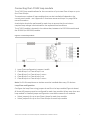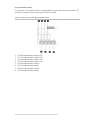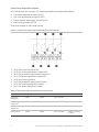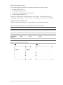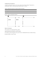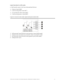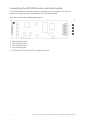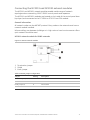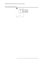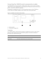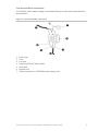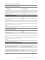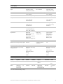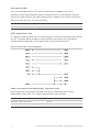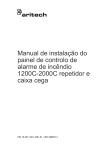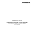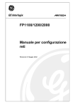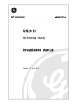
1
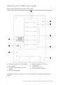
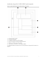
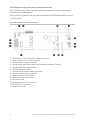
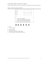
GE
Security
1200C-2000C Fire Alarm Control
Panel, Repeater, and Black Box
Installation Manual
P/N 1068351 • REV 10 • ISS 03JUN09
Copyright
© 2009 GE Security, Inc.
This document may not be copied in whole or in part or otherwise reproduced without prior
written consent from GE Security, Inc., except where specifically permitted under US and
international copyright law.
Disclaimer
The information in this document is subject to change without notice. GE Security, Inc.
(“GE Security”) assumes no responsibility for inaccuracies or omissions and specifically disclaims
any liabilities, losses, or risks, personal or otherwise, incurred as a consequence, directly or
indirectly, of the use or application of any of the contents of this document. For the latest
documentation, contact your local supplier or visit us online at www.gesecurity.eu.
This publication may contain examples of screen captures and reports used in daily operations.
Examples may include fictitious names of individuals and companies. Any similarity to names
and addresses of actual businesses or persons is entirely coincidental.
Trademarks and patents
GE and the GE monogram are trademarks of General Electric Company. Other trade names
used in this document may be trademarks or registered trademarks of the manufacturers or
vendors of the respective products.
Intended use
Use this product only for the purpose it was designed for; refer to the data sheet and user
documentation for details. For the latest product information, contact your local supplier or visit
us online at www.gesecurity.eu
Certification and compliance
2002/96/EC (WEEE directive): Products marked with this symbol cannot be disposed of as
unsorted municipal waste in the European Union. For proper recycling, return this product to
your local supplier upon the purchase of equivalent new equipment, or dispose of it at
designated collection points. For more information see: www.recyclethis.info.
2004/108/EC (EMC directive): Non-European manufacturers must designate an authorized
representative in the Community. Our authorized manufacturing representative is:
GE Security B.V., Kelvinstraat 7,
6003 DH Weert, The Netherlands.
2006/66/EC (battery directive): This product contains a battery that cannot be disposed of as
unsorted municipal waste in the European Union. See the product documentation for specific
battery information. The battery is marked with this symbol, which may include lettering to
indicate cadmium (Cd), lead (Pb), or mercury (Hg). For proper recycling, return the battery to your
supplier or to a designated collection point. For more information see: www.recyclethis.info.
Contact information
For contact information see our Web site: www.gesecurity.eu.
Content
Important information II
Introduction II
Product compatibility II
Support II
Limitation of liability II
Installation and commissioning 1
Cabinet layout for 1200C control panels 1
Cabinet layout for 2000C control panels 2
Inside door layout for 1200C-2000C control panels 3
General installation and connection guidelines 4
Connecting the LC1502 loop module 5
Connecting the SD2000 common I/O module 6
Connecting the FEP2000N main controller module 12
Connecting the NC2011 and NC2051 network modules 13
Connecting the LON2000 serial communication module 15
Connecting the ZE2016 and ZE2064 zone LED modules 16
Connecting the mains power supply 17
Connecting the batteries 24
Commissioning the control panel 26
Basic configuration options 29
Maintenance 30
Fire system maintenance 30
Battery maintenance 31
Technical specifications 32
Appendixes 35
Appendix A: Modules 35
Appendix B: Dimensions and weights 37
Appendix C: Maximum zones and loops 38
Appendix D: Cable specifications 39
Appendix E: Product compliance 41
1200C-2000C Fire Alarm Control Panel, Repeater, and Black Box Installation Manual
I
Important information
Introduction
This is the installation manual for GE Security FP1200C-2000C addressable fire
control panels, repeaters, and emulators. Read these instructions and all related
documentation entirely before installing or operating this product.
All 1200C-2000C control panels are designed to comply with the requirements of
European standards EN 54-2 for control and indicating equipment, and EN 54-4 for
power supply equipment)
For further details on EN 54 compliance and for a complete list of CPD-compliant
control panels in this range, see “Appendix E: Product compliance” on page 41.
Product compatibility
All models are compatible with GE Security Aritech fire detectors and manual call
points. Compatibility with third-party products cannot be guaranteed. Consult your
local supplier for further information.
Support
For assistance installing, operating, maintaining, and troubleshooting this product,
please contact your local supplier.
Limitation of liability
Installation in accordance with this manual, applicable codes, and the instructions of
the authority having jurisdiction is mandatory. GE Security shall not under any
circumstances be liable for any incidental or consequential damages arising from
loss of property or other damages or losses owing to the failure of GE Security
products beyond the cost of repair or replacement of any defective products.
GE Security reserves the right to make product improvements and change product
specifications at any time.
While every precaution has been taken during the preparation of this manual to
ensure the accuracy of its contents, GE Security assumes no responsibility for errors
or omissions.
II
1200C-2000C Fire Alarm Control Panel, Repeater, and Black Box Installation Manual
Installation and commissioning
WARNING: This product must be installed and maintained by qualified personnel
adhering to the CEN/TS 54-14 standard (or the corresponding national standard) and
any other applicable regulations.
Cabinet layout for 1200C control panels
Figure 1: Typical cabinet layout for 1200C control panels
1.
2.
3.
4.
5.
6.
7.
8.
FEP2000N mains controller module
PS1200N power supply interface module
LC1502 loop module
SD2000 common I/O module
PS2000N power supply unit
Earth stud
Fuse terminal block
12V batteries
For detailed module information for all control panels see “Appendix A: Modules” on
page 35
1200C-2000C Fire Alarm Control Panel, Repeater, and Black Box Installation Manual
1
Cabinet layout for 2000C control panels
Figure 2: Typical cabinet layout for 2000C control panels
1. FEP2000N mains controller module
2. Earth studs
3. PS1200N power supply interface
module
4. LC1502 loop modules
5.
6.
7.
8.
SD2000 common I/O module
12V batteries
Fuse terminal block
PS2000N power supply unit
For detailed module information for all control panels see “Appendix A: Modules” on
page 35.
2
1200C-2000C Fire Alarm Control Panel, Repeater, and Black Box Installation Manual
Inside door layout for 1200C-2000C control panels
Figure 3: Typical inside door layout for 1200C-2000C control panels
1.
2.
3.
4.
5.
6.
KP2000 keypad module
LCD1200 LCD screen
FC1200N or FC2012 host CPU module
NC2011 or NC2051 network module (optional)
ZE2016 or ZE2064 zone LED module
HDIS2000N or HDIS2000-F LED display module
For detailed module information for all control panels see “Appendix A: Modules” on
page 35.
1200C-2000C Fire Alarm Control Panel, Repeater, and Black Box Installation Manual
3
General installation and connection guidelines
Where to install the control panel
Make sure the installation location is free from construction dust and debris, and
immune to extreme temperature ranges and humidity (see “Technical specifications”
on page 32 for more information on the operating temperature and relative humidity
specifications).
Allow for enough floor and wall space so the panel can be installed and serviced
without any obstructions. The cabinet should be mounted so that the user interface is
at eye level.
Recommended cables
Recommended cables for your fire system are shown in the table below. For more
detailed information on cable characteristics and requirements see “Appendix D:
Cable specifications” on page 39.
WARNING: Failure to use the recommended cable may impact system performance.
Table 1: Recommended cables
Cable
Cable description
Maximum cable length
Mains cable
3 x 1.5 mm
N/A
Loop cable
Shielded, twisted pair cable
2 km
RS485 network cable
CAT5
800 m
Fibre optic network cable
ST duplex 50/125, 62.5/125, or
100/140
1.7 km (see note below)
LON network cable
CAT5
1.5 km
RS232 serial communication
cable
7-way RS232 null modem cable
with full handshaking
12 m
Note: Under ideal conditions the maximum distance between nodes is 1.7 km, but an
optical power budget calculation should be performed to determine the correct
maximum distance for each site.
Installing or replacing control panel modules
WARNING: Always back up site data before installing or replacing modules.
When control panel modules are replaced or additional modules installed, the control
panel automatically reconfigures and all site data is lost. Always back up site data
before installing or replacing modules.
4
1200C-2000C Fire Alarm Control Panel, Repeater, and Black Box Installation Manual
Connecting the LC1502 loop module
The LC1502 loop module allows for the connection of up to two Class A loops or up to
four Class B loops.
The maximum number of loop modules that can be installed will depend on the
control panel model – see “Appendix C: Maximum zones and loops” on page 38 for
more information.
A calculation should be performed for each loop to ensure that the minimum
required loop voltage is maintained for the expected load conditions.
The LC1502 module is located in the cabinet box, between the PS1200N module and
the SD2000 (or VDS2000) module.
Figure 4: LC1502 loop module
1.
2.
3.
4.
5.
Loop Class configuration jumpers A and B
Class B loop 1 or Class A loop 1 out
Class B loop 2 or Class A loop 1 return
Class B loop 3 or Class A loop 2 out
Class B loop 4 or Class A loop 2 return
Note: For EN 54 compliance an isolator must be installed after every 32 devices.
Loop Class configuration
Configure the loop Class using jumpers A and B on the loop module (Figure 4 above).
All three A/B jumpers must be configured for each loop module. When more than one
loop module is installed jumper configuration must be the same for all modules.
•
•
Select jumper A for up to two Class A loops for each loop module
Select jumper B for up to four Class B loops for each loop module
1200C-2000C Fire Alarm Control Panel, Repeater, and Black Box Installation Manual
5
Connecting the SD2000 common I/O module
The SD2000 common I/O module provides the common inputs and outputs for the
control panel.
The SD2000 module is located in the rear cabinet and is the last module in the group.
It is connected to the LC1502 module.
Note: This module is not included with French or German control panels.
Figure 5: SD2000 common I/O module
1.
2.
3.
4.
5.
6.
7.
8.
9.
6
IN5 fire routing return input (VdS mode only)
IN6 fire protection fault input (VdS mode only)
IN7 fire routing fault input (VdS mode only)
IN8 general input
OUT1 fire alarm equipment output
OUT2 fire routing equipment output
OUT3 fire protection equipment output
OUT4 fault routing output
OUT5 to OUT8 programmable relays 1 to 4
1200C-2000C Fire Alarm Control Panel, Repeater, and Black Box Installation Manual
Programmable relays
The common I/O module has four programmable relays. Each relay has common (C),
normally closed (NC), and normally open (NO) contacts.
Figure 6: Common I/O module programmable relays
1.
2.
3.
4.
5.
6.
7.
8.
OUT8 programmable relay 4 LED
OUT7 programmable relay 3 LED
OUT6 programmable relay 2 LED
OUT5 programmable relay 1 LED
OUT8 programmable relay 4
OUT7 programmable relay 3
OUT6 programmable relay 2
OUT5 programmable relay 1
1200C-2000C Fire Alarm Control Panel, Repeater, and Black Box Installation Manual
7
Class A loop supervised outputs
For Class A loops the common I/O module provides four supervised outputs:
•
•
•
•
Fire alarm equipment output (OUT1)
Fire routing equipment output (OUT2)
Fire protection equipment output (OUT3)
Fault routing output (OUT4)
All outputs supply 24 VDC when active.
Figure 7: Common I/O module supervised outputs for Class A loops
1.
2.
3.
4.
5.
6.
7.
8.
OUT4 fault routing output LED
OUT2 fire routing equipment output LED
OUT3 fire protection equipment output LED
OUT1 fire alarm equipment output LED
OUT4 fault routing output
OUT3 fire protection equipment output
OUT2 fire routing equipment output
OUT1 fire alarm equipment output
Table 2: Supervised output specifications for Class A loops
Output
Output number
termination
Polarity
Fire alarm
equipment
OUT1
3K3Ω
Non-reversed
Fire routing
equipment
OUT2
3K3Ω
Non-reversed
Fire protection
equipment
OUT3
3K3Ω
Non-reversed
Fault routing
OUT4
3K3Ω
Non-reversed
8
Behaviour
Active in normal
position
1200C-2000C Fire Alarm Control Panel, Repeater, and Black Box Installation Manual
Class B loop relay outputs
For Class B loops the common I/O module provides four relay outputs:
•
•
•
•
Sounder output (OUT1)
Fire brigade output (OUT2)
Fire protection equipment output (OUT3)
Fault routing output (OUT4)
Two relay configurations are available for each output. The relay behaviour is
configured using jumpers J2 to J7, J12 to J13, and J18 to J19 on the module PCB.
Configuration of outputs 1 to 3
Jumper configuration options for relay outputs 1 to 3 are shown below.
Jumper configuration options for relay outputs 1 to 3 with Class B loops
Output
Output number
Option 1
Option 2
Comments
Sounder
OUT1
J12 IN
J12 OUT
J18 OUT
J13 OUT
J13 IN
J19 OUT
J2 IN
J2 OUT
J18 OUT
J3 OUT
J3 IN
J19 OUT
J4 IN
J4 OUT
J5 OUT
J5 IN
Fire brigade
Fire protection
equipment
OUT2
OUT3
Figure 8: Jumper configuration options
1200C-2000C Fire Alarm Control Panel, Repeater, and Black Box Installation Manual
9
Configuration of output 4
Jumper configuration options for relay output 4 are shown below. The switch is
closed when there is a fault and open when there is no fault.
Jumper configuration options for output 4 with Class B loops
Output
Output number
Option 1
Option 2
Fire routing
OUT4
J6 IN
J6 OUT
J7 OUT
J7 IN
Comments
Figure 9: Jumper configuration options
Supervised inputs
The common I/O module has four inputs.
Input function for EN, NEN, and EP modes
In EN, NEN, and EP mode the four inputs have no dedicated function and are freely
programmable using I/O logic.
10
1200C-2000C Fire Alarm Control Panel, Repeater, and Black Box Installation Manual
Input function for VdS mode
In VdS mode inputs 5 to 8 are allocated as follows:
•
•
•
•
General input (IN8)
Fault routing fault input (IN7)
Fire protection fault input (IN6)
Fault routing return input (IN5)
Figure 10: Common I/O module supervised inputs in VdS mode
1.
2.
3.
4.
IN5 general input OR fault routing return input (VdS mode)
IN6 general input OR fire protection fault input (VdS mode)
IN7 general input OR fault routing fault input (VdS mode)
IN8 general input
1200C-2000C Fire Alarm Control Panel, Repeater, and Black Box Installation Manual
11
Connecting the FEP2000N main controller module
The FEP2000N main controller module is located in the rear cabinet. It is the first
module of the group and is connected to the PS1200N module.
Figure 11: Main controller module auxiliary inputs
1.
2.
3.
4.
5.
12
IN4 auxiliary input 4
IN3 auxiliary input 3
IN2 auxiliary input 2
IN1 auxiliary input
FC1200N or FC2012 host CPU module connector
1200C-2000C Fire Alarm Control Panel, Repeater, and Black Box Installation Manual
Connecting the NC2011 and NC2051 network modules
The NC2011 and NC2051 network modules enable a wide range of network
topologies when networking 1200C-2000C control panels and repeaters.
The NC2011 and NC2051 modules are located on the inside of the control panel door
(top layer) and connected to the FC1200N or FC2012 host CPU module.
General information
All network nodes use the ARCNET protocol. Every node on the network must have a
network module installed.
Where cabling runs between buildings or in high-noise or harsh environments a fibreoptic network should be used.
NC2011 network module for RS485 networks
Figure 12: NC2011 network module
1. Termination jumper
2. Shield
3. Earth jumper
Table 3: NC2011 jumper configuration
Jumper
Setting
Description
Termination jumper (T+)
A
Not terminated
B
Terminated
A
Not earthed
B
Earthed
Earth jumper (S)
1200C-2000C Fire Alarm Control Panel, Repeater, and Black Box Installation Manual
13
NC2051 network module for fibre-optic networks
Figure 13: NC2051 network module
14
1200C-2000C Fire Alarm Control Panel, Repeater, and Black Box Installation Manual
Connecting the LON2000 serial communication module
The LON2000 serial communication module allows serial communication between
1200C-2000C series addressable control panels and 700 series conventional control
panels. It cannot be used with repeaters.
The module is installed onto the P13, 20-PIN male connector of the FC1200N or
FC2012 host CPU module located on the inside of the control panel door.
Figure 14: LON2000 serial communication module
1. Service switch
2. Termination jumper (J1)
Termination
If a LON2000 serial communication module is installed into the first or last control
panel of a LON network, then the termination jumper (J1) must be inserted to
terminate the communication port.
Termination jumper (J1)
Description
Inserted
The serial communication port is terminated with 120Ω
Not inserted
The serial communication port is not terminated
1200C-2000C Fire Alarm Control Panel, Repeater, and Black Box Installation Manual
15
Connecting the ZE2016 and ZE2064 zone LED modules
The ZE2016 and ZE2064 zonle LED modules are used to increase the number of
visible zones for 1200C and 2000C control panels.
The maximum number of zone modules that can be installed will depend on the
control panel model – see “Appendix C: Maximum zones and loops” on page 38 for
more information.
The ZE2016 and ZE2064 modules are located on the inside of the control panel door
and are connected to the HDIS2000N or HDIS2000-F LED display module.
Caution: The ZE2016 and ZE2064 zone LED modules must ntot be installed together
in the same control panel.
16
1200C-2000C Fire Alarm Control Panel, Repeater, and Black Box Installation Manual
Connecting the mains power supply
Mains power should be sourced directly from a separate circuit breaker in the
building electrical supply distribution board. This circuit should be clearly marked,
have a bipolar disconnect device, and only be used for fire detection equipment.
Caution: Keep mains cables separate from other cabling to avoid potential short
circuits and interference. Always secure mains cables to the cabinet to prevent
movement.
Figure 15: Typical power supply connections for a 1200C control panel
1.
2.
3.
4.
5.
6.
7.
PS1200N power supply interface module
PS2000N power supply unit
Earth stud
Fuse terminal block
Incoming 230 VAC mains supply cable
12V batteries
Temperature sensor
Note: Panel layout may differ from illustration.
1200C-2000C Fire Alarm Control Panel, Repeater, and Black Box Installation Manual
17
PS2000N power supply unit connections
The PS2000N is the main power supply unit for 1200C-2000C control panels and
complies with all EN 54 requirements when used with these products.
Figure 16: PS2000N layout and connections
1. Fuse terminal block connector
2. PS1200N connector
18
1200C-2000C Fire Alarm Control Panel, Repeater, and Black Box Installation Manual
Fuse terminal block connections
The 230 VAC mains power supply is connected directly to the fuse terminal block as
shown below.
Figure 17: Fuse terminal block connections
1.
2.
3.
4.
5.
6.
7.
Earth stud
Fuse
Live wire
Incoming 230 VAC mains cable
Earth wire
Neutral wire
Cable connection to PS2000N power supply input
1200C-2000C Fire Alarm Control Panel, Repeater, and Black Box Installation Manual
19
PS1200N power supply interface module connections
The PS1200N power supply interface module manages the control panel power
requirements and distribution.
The PS1200N is located in the rear cabinet between the FEP2000N module and the
LC1502 module.
Figure 18: PS1200N layout and connections
1. FC1200N or FC2012 host CPU module connector
2. Potentiometer (LCD screen contrast)
3. Modem power supply connector
4. Power supply fault relay output configuration jumpers J7 and J8
5. Power supply fault relay output
6. 24 VDC auxiliary output
7. Internal printer power supply connector
8. Power and fault monitoring LEDs
9. Battery selection DIP switch
10. Battery startup push button
11. 5A battery fuse
12. Temperature sensor connector
13. PS2000N PSU connector
14. Battery connector
20
1200C-2000C Fire Alarm Control Panel, Repeater, and Black Box Installation Manual
Fault relay connection on the PS1200N
Configure the power supply fault relays using jumpers J7 and J8 beside the fault
output (see Figure 18 on page 20).
Figure 19: PS1200N fault relay jumper configurations
1. Normally open (NO)
2. Common (C)
3. Normally closed (NC)
Note: Components shown are mounted onto the PS1200N PCB and do not represent
field wiring.
The fault output is normally closed. The default setting for jumpers J7 and J8 is A.
Configuration options are:
J7 (pins for position B connected on PCB)
•
•
Position A = 3K3Ω
Position B = 0Ω
J8 (pins for position A connected on PCB)
•
•
Position A = 660Ω
Position B = 0Ω
1200C-2000C Fire Alarm Control Panel, Repeater, and Black Box Installation Manual
21
Power and fault monitoring LEDs on the PS1200N
The PS1200N includes five LEDs for power and fault monitoring.
Figure 20: PS1200N power and fault monitor LEDs
1.
2.
3.
4.
5.
Power LED
Earth fault LED
Charger fault LED
Battery voltage fault LED
Battery circuit resistance fault LED
LED
Colour
Description
Power
Green
Indicates the power supply status and power source. If the LED
is lit, then the is powered by the PS2000N power supply unit. If
the LED is off, then the power is supplied by batteries or the
module is without power.
Earth fault
Yellow
Indicates control panel earth faults. If the LED is lit, an earth
fault has been detected.
Charger fault
Yellow
Indicates the general status of the battery charger. If the LED is
lit, there is a fault with charging the batteries (incorrect voltage,
temperature sensor connection fault, microcontroller error etc.)
Battery voltage fault
Yellow
Indicates battery voltage faults. If the LED is lit, the battery
voltage is less than 21V, there are no batteries connected, or
there is a short circuit at the battery terminals.
Battery circuit resistance Yellow
fault
Indicates the results of a battery circuit resistance test. If the
LED is lit, the battery resistance is too high.
22
1200C-2000C Fire Alarm Control Panel, Repeater, and Black Box Installation Manual
24 VDC power supply connections for repeaters
24 VDC power supply connectors for repeaters are located on the termination board.
Figure 21: 24 VDC power supply connections
1.
2.
3.
4.
5.
6.
Fuse
+24V connector
-24V connector
Earth connector
Charger fail (normally shorted input)
Mains supply fail (normally shorted input)
1200C-2000C Fire Alarm Control Panel, Repeater, and Black Box Installation Manual
23
Connecting the batteries
The control panel requires two 12V, 7 to 45 Ah rechargeable sealed lead-acid
batteries (see table below).
Batteries must be installed in series using the bridge provided and connected to the
BAT CH terminals on the PS1200N power supply interface (see Figure 15 on page 17).
Polarity must be observed. No other equipment may be connected to the battery
terminals.
Table 4: Battery and battery installation
Battery
Battery location
12V - 7 Ah
Batteries are installed inside the control panel cabinet
12V - 7.2 Ah
Batteries are installed inside the control panel cabinet
12V - 12 Ah
Batteries are installed inside the control panel cabinet
12V - 17 Ah
Batteries are installed inside the control panel cabinet
12V - 18 Ah
Batteries are installed inside the control panel cabinet
12V - 24 Ah
Batteries must be installed externally
12V - 26 Ah
Batteries must be installed externally
12V - 45 Ah
Batteries must be installed externally
Note: 45 Ah batteries may not be used with FP1200C, FR1200, or FR2000 panels.
Once batteries are installed, the battery type must be set using the battery selection
DIP switch. See “Charging batteries” below.
Charging batteries
In accordance with EN 54-4, installed batteries may be charged by the control panel.
To ensure correct charging, the type of battery used must be set using the battery
selection DIP switch on the PS1200N (see Figure 16 on page 18). DIP switch settings
are shown in the table below.
Caution: Selecting an incorrect charge rate may damage batteries.
Table 5: Battery selection DIP switch configuration
1
2
3
4
Battery type
Charge rate at 27.3 VDC
OFF
OFF
OFF
ON
7 and 7.2 Ah
0.5 A
OFF
OFF
ON
OFF
12, 17, and 18 Ah
1A
OFF
ON
OFF
OFF
24 and 26 Ah
1.5 A
ON
OFF
OFF
OFF
45 Ah
3A
Note: If more than one DIP switch is ON the lowest charging rate will be used.
If the control panel indicates a Battery Test Fail error, then the batteries may need to
be replaced. For more information see “Battery maintenance” on page 31. For battery
life calculations see “Battery capacity calculation” on page 34.
24
1200C-2000C Fire Alarm Control Panel, Repeater, and Black Box Installation Manual
Starting up on battery power
If mains power is not available the control panel may be powered up using battery
power. To do this, press the battery startup button on the PS1200N power supply
interface module (see Figure 18 on page 20).
Third-source power supply
An optional 9V PP3 battery may be installed as a third-source power supply. The
third-source battery is connected to the FC1200N or FC2012 host CPU module.
1200C-2000C Fire Alarm Control Panel, Repeater, and Black Box Installation Manual
25
Commissioning the control panel
FC1200N or FC2012 host CPU module configuration
Before starting up the control panel the FC1200N or FC2012 host CPU module must
be configured as follows:
•
•
Memory switch LOCKED
Service Mode switch OFF
The memory should only be unlocked when prompted during the initial start-up
procedure.
Commissioning checklist
Check the following before starting-up the control panel for the first time:
•
Check the interior of the control panel for any loose cabling and for any damage
that may have occurred during installation.
•
Check that all harnesses are securely plugged into the correct connectors.
•
Check that both the mains switch and the battery ON/OFF switch are off.
•
Check that all mains and battery cables are connected correctly and that polarity
has been observed.
•
Check that the lithium battery on the host CPU module is enabled (jumper J5 –
located above the battery – is inserted) and unlock the memory.
•
Check that the control panel is well earthed at the earth terminals provided. The
earth must be directly wired to the distribution board earth. This is required for
safety and interference suppression.
•
Check that all repeaters, network modules, and field devices are connected and
that their addresses have been set correctly (where applicable).
•
Check that the FC1200-FC2012 host CPU module has the Service Mode switch off
and that the memory is locked.
•
Check that any installed loop isolators use correct polarity.
•
Check all field wiring with a multimeter for short circuits, continuity, and earth
faults. If isolators have been used in the loop wiring, then one wire of the loop will
not have continuity. Continuity, earth fault and short circuit must be checked
between each isolator.
WARNING: Do not use a Megger on the loops as this may damage connected
devices.
26
1200C-2000C Fire Alarm Control Panel, Repeater, and Black Box Installation Manual
Commissioning procedure
Once all final checks have been completed the control panel may be commissioned.
To do this, do the following:
1. Switch the mains power on at the power supply or connect the 24 V to the 24 V
supply board.
2. The internal buzzer will sound and the control panel product code will be
displayed on the LCD screen (with the revision of host firmware, firmware code
and the creation date of the firmware). If this does not happen do not proceed.
Check that the mains supply is present and that all fuses are correct.
3. Switch the battery On/Off switch to ON (230 V model only).
4. Check that the battery float voltage is between 27 and 28 V using a voltmeter
(ensuring that the voltage remains stable for approximately 5 minutes). If the
voltage is significantly less, then check the battery condition and possible
overloads in the field.
5. If there are visible signs of the power supply overheating, then do not proceed.
Disconnect batteries and all field wiring, and investigate the cause of the problem.
6. The control panel will now perform internal checks and any faults detected will be
displayed on the LCD screen. The total number of faults is reported (on line 8). Use
the scroll button to view the faults. See Table 6 below for a list of possible faults
that may be reported.
7. Any faults reported should be fixed before proceeding. Use the Reset button to
refresh the fault report.
8. Enable all loop devices (via the Setup menu or using a PC and configuration
software).
9. Eliminate any alarms reported and ensure that no devices that should be active
are reported as disabled.
10. Check all output relays for correct switching.
11. Configure your Panel ID.
Table 6: Common faults at first-time start-up
Fault type
Action required
Loop overload fault
Check the reported loop for short circuits.
Earth fault
Check all earth connections
Battery fail
Check battery charging
Sounders or fire brigade fault short or
open circuit fault
Check that all supervised inputs are terminated correctly
with a 3K3Ω resistor
Device fault
Check all devices and connections
Double address fault
Check all device addresses
1200C-2000C Fire Alarm Control Panel, Repeater, and Black Box Installation Manual
27
Commissioning networks
Once the control panel has been commissioned correctly, the following steps are
required to initialize and configure a network.
1. Configure the network setup (via the Setup menu or using a PC)
2. Investigate and fix all faults that are reported
3. Check the status of the systems on the ARCNET network that are configured to
communicate with the repeater. Faults regarding communication with repeater
node identification address should disappear when the ARCNET network is
operational
4. Check all connections to panels by emulating them
5. Check panel fault reporting by switching off each panel one by one and checking
that the missing panel is reported by the other panels in the network
6. Check fire and fault reporting
7. Check all that all network input and output devices are working correctly
8. Reset all repeaters and control panels
28
1200C-2000C Fire Alarm Control Panel, Repeater, and Black Box Installation Manual
Basic configuration options
The protocol, operating mode, and language are selected via System Setup menu on
the control panel LCD screen (System > Configuration > System Setup).
Protocol and operating mode
The following protocols are supported:
•
•
900 series
2000 seriesl
The following operating modes are supported:
•
•
•
•
•
EN mode
VdS mode
NEN mode
EP mode
BS mode
Note: VdS mode is only available on control panels with a VDS2000 module installed.
Language groups
Each panel is shipped with one language group. A language group may include up to
five languages.
Table 7: 1200C-2000C language groups
Group 0
Group 1
Group 2
Group 3
Group 4
Group 5
English
English
English
English
English
English
Dutch (Holland)
Polish
Danish
Lithuanian
Italian
Romanian
Dutch (Belgium) Hungarian
Swedish
Estonian
Spanish
Greek
French
Czech
Norwegian
Latvian
Portuguese
Luxemburgish
German
Slovak
Finnish
Russian
Brazilian
English
LCD contrast
The LCD screen contrast can be adjusted using the potentiometer on the PS1200N
power supply interface module (see “PS1200N power supply interface module
connections” on page 20).
1200C-2000C Fire Alarm Control Panel, Repeater, and Black Box Installation Manual
29
Maintenance
The following maintenance procedures should be performed. by qualified personnel
adhering to the CEN/TS 54-14 standard and any applicable local authority laws.
Fire system maintenance
Your fire system must be regularly tested and serviced in order to ensure its reliable
operation. The following maintenance routine is recommended.
Daily Verification
•
Check that the panel indicates normal operation. If it does not, check that any
fault indicated is recorded in the log book and reported to the maintenance
personnel.
•
Check that any fault warning recorded the previous day has received attention.
Quarterly Verification
•
Check the log book entries and that any necessary action has been taken.
•
Check the state of the batteries and corresponding connections.
•
Visually inspect the fire panel for signs of moisture or other deterioration.
•
Test the alarm, fault and ancillary functions of the fire panel.
Annual Verification
•
Carry out the recommended daily and quarterly inspection and test routines.
•
Check each detector for correct operation in accordance with the manufacturer's
recommendations.
•
Visually inspect all cable fittings and equipment to ensure that no damage has
taken place.
•
Visually inspect all electrical connections to make sure that they are securely
fastened, that they have not been damaged and that they are appropriately
protected.
•
Visually inspect the manual call points, detectors and sounders to ensure that no
structural or occupancy changes have affected their location requirements.
Cleaning the control panel
Keep the control panel clean inside and outside. Carry out periodic cleaning using a
damp cloth for the outside.
Do not use products containing solvents to clean the unit. Do not clean the inside
with liquid products.
30
1200C-2000C Fire Alarm Control Panel, Repeater, and Black Box Installation Manual
Battery maintenance
Batteries must be replaced periodically as recommended by the manufacturer. The
useful life of the battery is approximately 4 years. Avoid the total discharge of the
batteries.
Battery test fail
When the control panel indicates that the battery test has failed, check the following:
•
That the battery leads are in good condition
•
That the battery leads are connected securely and correctly at the battery and at
the panel
•
That the control panel event log does not indicate a mains failure in the last
twenty-four hours
If the leads are in good condition, all connections are correct, and the control panel
continues to report that the test has failed twenty-four hours after the last mains
failure, then the batteries should be replaced immediately.
Replacing batteries
To replace the batteries, do the following:
1. Disconnect and remove the existing batteries from the cabinet.
2. Install and connect the replacement batteries using the bridge provided. Observe
correct polarity.
Always use the recommended replacement batteries (see “Connecting the batteries”
on page 24).
Dispose of used batteries according the European regulations and/or instructions
from local authorities.
1200C-2000C Fire Alarm Control Panel, Repeater, and Black Box Installation Manual
31
Technical specifications
Mechanical and environmental specifications
Dimensions (W x H x D
Small cabinet
Large cabinet
445 x 445 x 120 mm
810 x 445 x 120 mm
Colour
RAL9016 Traffic White
IP rating
IP54
Operating temperature
−5°C to +40°C
Storage temperature
−20°C to +60°C
Loop specifications (2000 protocol)
Maximum number of loops per panel
See “Appendix C: Maximum zones and loops” on
page 38
Loop overload current
> 500 mA
Loop operating load
Max. 100 mA
Maximum number of addressable devices per
loop
128 per 2 km of cable
Maximum number of addressable devices per
1024
panel including I/O devices, detectors and manual
call points
Maximum number of addressable detectors
and/or manual call points per panel
512 (as defined by EN 54-2)
Loop specifications (900 protocol)
Maximum number of loops per panel
See “Appendix C: Maximum zones and loops” on
page 38
Loop overload current
> 500 mA
Loop operating load
Max. 100 mA
Maximum number of addressable devices per
loop
126 per 2 km of cable
Maximum number of addressable devices per
1008
panel including I/O devices, detectors and manual
call points
Maximum number of addressable detectors
and/or manual call points per panel
512 (as defined by EN 54-2)
Input and output specifications (SD2000/FEP2000N)
SD2000 IN1 to IN4
3K3Ω termination
SD2000 OUT1 and OUT2 (loop Class A)
24 V / 0.8 A (max. supervision 5V)
SD2000 OUT3 and OUT4 (loop Class A)
24 V / 0.1 A (max. supervision 5V)*
SD2000 OUT1 to OUT4 (loop Class B)
3K3Ω / 680Ω switched output
SD2000 OUT5 to OUT8 max. switching current
2A at 24 VDC
SD2000 OUT5 to OUT8 max. power rating
60 W DC
FEP2000N IN1 to IN4
15 VAC or 20 to 28 VDC / 3 A
32
1200C-2000C Fire Alarm Control Panel, Repeater, and Black Box Installation Manual
Power supply
Input
Output
FR1216C
FR2064C
All other panels
230 VAC (+10%, 15%), 50 Hz (±10%)
21 to 28 VDC
230 VAC (+10%, 15%), 47 to 63 Hz
50 VA
24V standby battery
200 VA
21 to 28 VDC
21 to 28 VDC
24V standby battery
24V standby battery
Aux. Power:
Aux. Power
19 to 28.8 VDC
100 mA (max.)
19 to 28.8 VDC
1 A (max.)
Modem:
Battery charge:
5 VDC (±0.1V)
75 mA (max.)
27.3 VDC at 20°C,
36 mV/°C
Battery charge:
27.6 VDC (±0.2V) at
25°C, 300 mA (max.)
Supervised
Mains fail
Mains fail
Battery disconnect
Charger fail
Battery flat
Flat battery cut-out
Earth fault
Auxiliary supply fault
Input voltage
Earth fault
Charger fault
Battery loss
Battery fault
Mains fuse
T 0.8A 250V
T 1A 250V
T 2A 250V
0.3 A (no options
installed)
1A
Maximum current (primary input) 250 mA
Maximum output ripple voltage
±300 mV
±300 mV
Fault relay (subject to jumper
configuration)
Maximum switching
current:
Maximum switching
current:
2A at 24 VDC
2A at 24 VDC
Maximum power
rating:
Maximum power
rating:
50 W
50 W
Current requirements
Status
System
Aux.
Printer
Modem
Loops*
Sounders
Total
Standby
200 mA
1A
100 mA
200 mA
340μA per
device
0
< I max a.
Alarm
200 mA +
10 mA per
zone card
1A
100 mA
200 mA
200 mA
340μA per
device plus
80 mA per loop
1A
< I max b.
4A
* Do not exceed 250 mA per loop.
1200C-2000C Fire Alarm Control Panel, Repeater, and Black Box Installation Manual
33
Supplementary electrical information
FR1200C-2000C
FP1200C-2000C
I min
250 mA
250 mA
I max. a
1A
1A
I max. b
3.5 A
4A
Ri max
0.5Ω
0.5Ω
Battery voltage (final)
21 V
21 V
Battery voltage (fully charged)
27.3 V at 20ºC (36mV/ºC)
27.3 V at 20ºC (36mV/ºC)
Batteries
7 Ah to 26 Ah
7 Ah to 45 Ah
Battery capacity calculation
Battery capacity is calculated with the following formula:
C = (Standby current × Standby time) + (Alarm current × Alarm time)
Calculation example for 24 hours standby time and 30 minutes in alarm:
System data:
•
•
•
•
•
•
1 x zone module
250 mA at FEP2000N auxiliary output
1 x internal printer (not supplied)
No modem
2 x loops with 100 devices per loop
100 mA at SD2000 sounders output
Status
System
Aux.
Printer
Modem
Loops*
Sounders
Total
Standby
200 mA
0.25 A
100 mA
0
340μA × 100 × 2
= 68 mA
0
618 mA
Alarm
200 mA +
100 mA =
300 mA
0.25 A
100 mA
0
340μA × 100 × 2
+ (80 mA × 2) =
228 mA
100 mA
978 mA
C = (0.618 A × 24 Hrs) + (0.978 A × 0.5 Hrs) = 15.312 Ah.
Closest value is 18 Ah.
34
1200C-2000C Fire Alarm Control Panel, Repeater, and Black Box Installation Manual
Appendixes
Appendix A: Modules
Installed modules will vary depending on panel model and region. For a complete
listing of panel/module configurations see page 36.
Standard modules
The following modules are installed in all control panels:
•
•
•
•
HDIS2000N or HDIS2000-F LED display module
FC1200N or FC2012 host CPU module
KP2000 keypad module (excluding black boxes)
LCD1200 LCD screen
A selection of the following modules may also be installed:
•
•
•
•
•
•
•
•
•
•
ZE2016 or ZE2064 zone LED module
FEP2000N main controller module
LC1502 loop module (except repeaters)
SD2000 common I/O module or VDS2000 VdS interface module
PS1200N power supply interface module
PS2000N power supply unit
PSDC2000 24V power supply interface module
NC2011 RS485 network module
NE2011 RS485 network extension module
LON2000 serial communications module
Optional modules
In addition to the above the following optional modules may also be installed if
required:
•
•
•
•
NC2051 fibreoptic network module
NE2051 fibreoptic network extension module
MOD2000 modem
RB2016 relay module
Module location
The following table indicates the installation location for each module.
Table 8: 1200C-2000C module installation location
Module
Installation location
HDIS2000N or HDIS2000-F
Inside the cabinet door (bottom layer)
FC1200N or FC2012
Inside the cabinet door (top layer)
KP2000
Inside the cabinet door (bottom layer)
LCD1200
Inside the cabinet door (top layer)
ZE2016 or ZE2064
Inside the cabinet door (bottom layer)
1200C-2000C Fire Alarm Control Panel, Repeater, and Black Box Installation Manual
35
Module
Installation location
FEP2000N
Inside the cabinet box
LC1502
Inside the cabinet box
SD2000
Inside the cabinet box
PS1200N
Inside the cabinet box
NC2011
Inside the cabinet door (top layer)
NC2051
Inside the cabinet door (top layer)
LON2000
Inside the cabinet door (top layer)
RB2016
Inside the cabinet box
Installed modules for fire panels, repeaters, and black boxes
The modules installed in each control panel are listed in the following tables. These
listings exclude the HDIS2000, FC1200-FC2012, KPD2000, and LCD1200 modules.
Table 9: Fire panel modules
Panel
Modules
FP1216N
ZE2016
FEP2000N
PS1200N
LC1502
SD2000
PS2000N
FP1264N
ZE2064
FEP2000N
PS1200N
LC1502
SD2000
PS2000N
FP28255C
ZE2064
FEP2000N
PS1200N
LC1502
SD2000
PS2000N
FP2864C
ZE2016
FEP2000N
PS1200N
LC1502
SD2000
PS2000N
Regional variants:
•
•
•
German panels have a VDS2000 module instead of the SD2000 module
French panels do not have the SD2000 module
Danish and Swedish panels have the LON2000 module
Table 10: Repeater and global repeater modules
Panel
Modules
FR1216N
ZE2016
---
PS1200
---
NC2011
NE2011
FR1264N
ZE2064
---
PS1200
---
NC2011
NE2011
FR20255N
ZE2064
---
PSH2000
PSDC2000
NC2011
NE2011
FR2064N
ZE2016
---
PSH2000
PSDC2000
NC2011
NE2011
FRG20255N
ZE2064
FEP2000N
PS1200N
PS2000N
NC2011
NE2011
GR2064C
ZE2016
---
PS1200N
PS2000N
NC2011
NE2011
PS1200N
LC1502
PS2000N
NC2011
NE2011
Table 11: Black box modules
Panel
Modules
FB2800C
FEP2000N
36
1200C-2000C Fire Alarm Control Panel, Repeater, and Black Box Installation Manual
Appendix B: Dimensions and weights
Two cabinet sizes are available:
Cabinet size
Dimensions (mm)
Colour
Small
445 x 445 x 120
RAL9016 (Traffic White)
Large
810 x 445 x 120
RAL9016 (Traffic White)
Cabinet use for each type of control panel is as follows:
Table 12: 1200C-2000C dimensions and weights
Control panel
Cabinet size
Weight (kg)
FP1216C
Small
9
FP1264C
Small
9
FR1216C
Small
9
FR1264C
Small
9
FP2864C
Large
15
FP28255C
Large
15
FR2064C
Large
15
FR20255C
Large
15
FRG20255C
Large
15
GR2064C
Large
15
Note: Weight is approximate and excludes batteries
1200C-2000C Fire Alarm Control Panel, Repeater, and Black Box Installation Manual
37
Appendix C: Maximum zones and loops
The maximum number of zones and zone modules, loops and loop modules for each
panel are shown in the table below.
Table 13: 1200C-2000C maximum zones and loops
Control
panel
Maximum number
of zones
Maximum number
of zone modules
Maximum number
of loops
Maximum number
of loop modules
FP1216C
16
1 x ZE2016
4A / 8B
2 x LC1502
FP1264C
64
1 x ZE2064
4A / 8B
2 x LC1502
FR1216C
16
1 x ZE2016
N/A
N/A
FR1264C
64
1 x ZE2064
N/A
N/A
FP2864C
64
4 x ZE2016
8A / 8B
4 x LC1502
FP28255C
255
4 x ZE2064
8A / 8B
4 x LC1502
FR2064C
64
4 x ZE2016
N/A
N/A
FR20255C
255
4 x ZE2064
N/A
N/A
FRG20255C 255
4 x ZE2064
N/A
N/A
GR2064C
4 x ZE2016
N/A
N/A
64
Note: For control purposes the absolute maximum number of zones is 255.
38
1200C-2000C Fire Alarm Control Panel, Repeater, and Black Box Installation Manual
Appendix D: Cable specifications
Mains power cable
The recommended mains cable is 3 x 1.5 mm² (live, neutral, earth).
Loop cable
A twisted pair cable is required to ensure data integrity. Shielded, fireproof cable is
highly recommended. If shielded cable is used, then cable shield continuity should be
observed.
Maximum cable length
2 km (cable Ø 1 mm)
Maximum cable capacitance
300 nF / km
Maximum total resistance
100Ω
RS485 network cable
The recommended cable is CAT5 with a characteristic impedance of 100 Ω.
Note: If the total cable length for the network exceeds 800 m and / or 32 nodes, we
recommend the use of fibre-optic cabling.
End-of-line termination resistors need to be used to match the cable characteristic
impedance to prevent reflections
Maximum cable length (bus and dual bus
topology)
800 m
Maximum number of nodes (bus and dual bus
topology)
32
When shielded cable is used, shields must be earthed at one point only. The shield of
the cable must be continued between nodes using the terminal provided on the card.
Fibre-optic network cable
The recommended fibre-optic cable is a straight tip (ST) duplex with a fibre width of
50/125, 62.5/125 or 100/140 µm.
Fibre-optic networks may use more than 32 nodes. The maximum distance between
nodes under ideal conditions is 1.7 km, but an optical power-budget calculation
should be performed to determine the correct maximum distance for each site.
1200C-2000C Fire Alarm Control Panel, Repeater, and Black Box Installation Manual
39
LON network cable
The recommended cable is CAT5 with a characteristic impedance of 100 Ω.
Maximum cable length between nodes is limited. End-of-line termination resistors
need to be used to match the cable characteristic impedance to prevent reflections.
The use of stub wiring is not recommended.
Maximum cable length (bus topology)
1.5 km
Maximum number of nodes (bus topology)
32
RS232 null modem cable
A 7-way null modem cable with full handshaking is used to connect the control panel
to a PC. The figure below shows the required DB9 control panel to PC (female to
female) cable configuration. The cable length should not exceed 12 m.
Figure 22: Null modem cable configuration
Output connections from addressable, supervised units
We recommend that shielded cable be used for all output connections from
addressable, supervised units. Cable characteristics are as follows:
Maximum output resistance
30Ω
Maximum output capacitance
120 nF
Maximum recommended cable length
500 m
40
1200C-2000C Fire Alarm Control Panel, Repeater, and Black Box Installation Manual
Appendix E: Product compliance
EN 54-2 compliance for 1200C-2000C control panels with the SD2000 module
Control panels with the SD2000 module installed have the following options with
requirements according to EN 54-2:
Table 14: EN 54-2 options with requirements with the SD2000 module
Clause
Description
7.8
Output to fire alarm devices
7.9
Output to fire routing equipment
7.10
Output to fire protection equipment
7.11
Delay to output
7.12
Dependency on more than one alarm signal
7.13
Alarm counter
8.4
Total loss of the power supply
9.5
Disablement of addressable points
10
Test
EN 54-2 compliance for 1200C-2000C control panels with the VDS2000 module
Control panels with the VDS2000 module installed have the following options with
requirements according to EN 54-2:
Table 15: EN 54-2 options with requirements with the VDS2000 module
Clause
Description
7.8
Output to fire alarm devices
7.9
Output to fire routing equipment (+ VDE0833)
7.10
Output to fire protection equipment (+ VdS requirements)
7.11
Delay to output
7.12
Dependency on more than one alarm signal (+ VDE0833)
7.13
Alarm counter
8.4
Total loss of the power supply
8.9
Output to fault routing equipment
9.5
Disablement of addressable points
10
Test
Control panels with the VDS2000 module also allow for:
•
•
•
•
•
Interface to FBF
Interface to FAT
interface to FSK
interface to Hauptmelder
interface to EMZ
1200C-2000C Fire Alarm Control Panel, Repeater, and Black Box Installation Manual
41
Construction Products Directive (CPD)
Details of the CPD certification for 1200C-2000C fire panels and global repeaters are
shown below.
Table 16: CPD certification for 1200C-2000C series fire panels and global repeaters
Certification
Certification body
1134
Certificate number
1134-CPD-069
Manufacturer
GE Security B.V., Kelvinstraat 7,6003 DH Weert, The Netherlands.
42
1200C-2000C Fire Alarm Control Panel, Repeater, and Black Box Installation Manual
1200C-2000C Fire Alarm Control Panel, Repeater, and Black Box Installation Manual
43