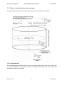
1
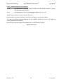
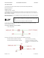
Garrecht Avionik GmbH
TRX-1500 ADS-B Traffic Monitor
User Manual
TRX-1500
ADS-B / FLARM® Trafficsensor
User Manual
Installation Manual
© 2012 - Garrecht Avionik GmbH, 55411 Bingen/Germany
Revision: 1.0a
1
31 JAN 2012
Garrecht Avionik GmbH
TRX-1500 ADS-B Traffic Monitor
User Manual
Record of Revisions
Always keep this page in front of this document.
Date
Revision Pages Description of Change
Inserted
by
31 JAN 2012
1.0
JG
Revision: 1.0a
All
released
2
31 JAN 2012
Garrecht Avionik GmbH
TRX-1500 ADS-B Traffic Monitor
User Manual
Table of contents
Record of Revisions ............................................................................................................................................ 2
Table of contents................................................................................................................................................. 3
Preface ............................................................................................................................................................... 4
Unpacking the unit............................................................................................................................................... 5
Important Information about integral FLARM® module.......................................................................................... 6
1. Principles ........................................................................................................................................................ 7
1.1. General.................................................................................................................................................... 7
1.2. Output of position data and warnings ........................................................................................................ 8
1.2.1. Position data:......................................................................................................................8
1.2.2. Warnings: ...........................................................................................................................9
1.3. Data output (collision warnings und position indication) ........................................................................... 10
1.4. Audible traffic warnings .......................................................................................................................... 10
1.5. Transponder signals, FLARM® signals and system behaviour ................................................................. 11
1.5.1. Mode-S Extended Squitter with ADS-B out........................................................................11
1.5.2. Mode-S Squitter................................................................................................................11
1.5.3. Mode-S Replies ................................................................................................................11
1.5.4. FLARM®...........................................................................................................................11
1.6. Limits of the Systems ............................................................................................................................. 12
1.6.1. General.............................................................................................................................12
1.6.2. The TRX-1500 system provides ........................................................................................12
1.6.3. The TRX-1500 system does NOT provide .........................................................................12
2. Aircraft installation ......................................................................................................................................... 13
2.1. General.................................................................................................................................................. 13
2.2. Mechanical installation ........................................................................................................................... 13
2.3. Antenna installation................................................................................................................................ 14
2.3.1. General.............................................................................................................................14
2.3.2. Antenne cable and connectors..........................................................................................14
2.3.3. ADS-B Antenna ................................................................................................................14
2.3.4. FLARM TX/RX Antenna ....................................................................................................15
2.3.5. GPS Antenna....................................................................................................................15
2.4. Wiring (power supply and data) .............................................................................................................. 16
2.4.1. USB interface ...................................................................................................................16
2.4.2. Power Supply ...................................................................................................................16
2.4.3. 3V3 DC Power output .......................................................................................................16
2.4.4. Data interfaces (Port-1 to Port-3).......................................................................................16
2.4.5. Audio interface..................................................................................................................19
2.5. microSD Card Slot ................................................................................................................................. 20
2.5.1. System behavior with inserted memory card (microSD-Card) ............................................21
3. Firmware updates (FLARM + TRX-1500) via mircoSD-Card............................................................................ 22
3.1. Step by step instruction .......................................................................................................................... 23
3.1.1. General information about required files............................................................................23
3.1.2. Prepare your microSD memory card (SDSC, no SDHC type) for the update process.........23
3.1.3. Performe the update process ............................................................................................23
4. PC Software TRX-TOOL................................................................................................................................ 24
4.1. Step by Step instruction for successfull installation process ..................................................................... 24
4.2. Software and firmware release ............................................................................................................... 25
4.3. Program and firmware update via internet ............................................................................................... 25
4.4. Device configuration............................................................................................................................... 26
5. Check list installation and konfiguration .......................................................................................................... 31
6. Specifications TRX-1500................................................................................................................................ 32
7. Installation schematic diagram ....................................................................................................................... 33
8. Dimensions ................................................................................................................................................... 34
9. Traffic indication with Garmin TIS compatible devices..................................................................................... 35
9.1. ADS-B and Flarm-Targets ...................................................................................................................... 35
9.1.1. Dynon SkyView:................................................................................................................35
9.1.2. Garmin GPS / AERA:........................................................................................................35
9.2. Mode-S only targets ............................................................................................................................... 36
9.2.1. Dynon SkyView:................................................................................................................36
Revision: 1.0a
3
31 JAN 2012
Garrecht Avionik GmbH
TRX-1500 ADS-B Traffic Monitor
User Manual
Preface
Many thanks for purchasing the TRX-1500 traffic sensor.
The TRX-1500 combines a high performance ADS-B receiver with an integral FLARM(R) module. The
system provides interfaces for connecting two external Displays (CDTI) and a GPS interface to be
connected to a Mode-S transponder (i.e. Garrecht Avionik VT-01, VT-02, VT-2000) with ADS-B out
capability.
To avoid malfunction, reading and understanding of all chapters of this manual is required.
Limitations of the system are described in the chapter „System Limitations”
A detailed data port specification is described in the “TRX Data Port Specifications” manual, which is
available on request from the manufacturer.
New releases of manuals or firmware udpates are published on the manufacturers website
www.garrecht.com
Your feedback or suggestions for improving the system are welcome. Please contact us via email:
[email protected]
This manual provides all information, that is required for proper installation and safe operation.
For more information and addtional support, please contact your TRX-1500 dealer. ´
To avoid damage, please do not open the system housing.
The following symbols and terms are used in this manual:
Warning
Warning statements identify conditions or practices that could result in
injury or loss of life
Caution
Caution statements identify conditions or practices that could result in
damage of this product or other property.
Important note:
Indicates important or usefull information. It is strongly recommended to
read, understand and follow the statement.
Revision: 1.0a
4
31 JAN 2012
Garrecht Avionik GmbH
TRX-1500 ADS-B Traffic Monitor
User Manual
Unpacking the unit
The TRX-1500 system is supplied with the following:
•
•
•
•
•
•
•
•
•
System unit TRX-1500
USB interface cable
1090 MHz antenna + antenna cable
FLARM®- antenna + antenna cable (
GPS antenna
Antenna ground plane
D-SUB 15 HD (f) connector
Connector shell
This manual
If one or more parts are missing, please contact your supplier of the TRX-1500.
Required parts for proper operation
•
External display devices (CDTI), i.e. Butterfly, Dynon SkyView, FlymapL, Garmin GPS
39x/49x/69x, Aera, PDA with appropriate software (WinPilot, PocketStrePla, SeeYou mobile)
Options (not delivered with the TRX-1500)
•
•
Antenna line extension
Wiring harness (15 pol. HD)
These options will be supplied by your TRX-1500 supplier.
Revision: 1.0a
5
31 JAN 2012
Garrecht Avionik GmbH
TRX-1500 ADS-B Traffic Monitor
User Manual
Important Information about integral FLARM® module
The TRX-1500 is equipped with an integral FLARM® module. FLARM is a very popular collision
avoidance system for general aviation and gliders, which is installed in over 17.000 aircraft worldwide.
FLARM® features at a glance:
•
•
•
•
•
Situational awareness display. Collision warning (audible and visible) if other aircraft is also
FLARM® equipped.
Obstacle warnings
Intelligent trajectory prediction, also under unconventional conditions (i.e. thermaling gliders) to
reduce pseudo warnings
Typicial range: 4-8 km
Operating in free ISM Band
Detailed information about the FLARM® system can be obtained under
www.flarm.com
To keep all FLARM® up to date and to improve the system,
mandatory updates are required from time to time (every 3 to 5 years).
These updates are mandatory in order to keep your FLARM® alive.
After the expiration date, FLARM(R) stops working.
Setting up the integral FLARM® module requires the use of the
FLARM® tool and a microSD memory card. For transfering your
personnel configuration, store the desired setup to a memory card and
insert this card into your TRX-1500.
Unless otherwise stated, do not use the FLARM® tool for setting up the
internal FLARM® module.
Mandatory updates are required to improve the whole FLARM® network without respecting downward
compatibility. The aviation typical periodic maintenance has been extended to electronic systems.
The expiry date of the current firmware is Feb. 28 2015
Detailed information about the udpate process can be downloaded from
www.garrecht.com
All required files are provided via this website.
Please do not send the device to the manufacturer
for firmware updates!!
Revision: 1.0a
6
31 JAN 2012
Garrecht Avionik GmbH
TRX-1500 ADS-B Traffic Monitor
User Manual
1. Principles
1.1. General
Automatic Dependent Surveillance – Broadcast is a modern ATC system for broadcast aircraft
position data. Transponders which are connected to a GPS system transmit her own position and other
flight data, like call sign, Mode-S address, speed and altitude as well as track and vertical speed. The
transponder transmits these data periodically – typically once per second – like a radio station
(Broadcast).
TRX-1500 contains a sensitive 1090 MHz receivers with complex signal processing unit. Transponder
signals broadcasted by other aircraft are received, processed and decoded.
Data from the integral FLARM® will be extended by the data received from the TRX-1500 ADS-B
receiver and indicated on an external cockpit display.
To enhance display capability, traffic data will be provided via two interfaces for connecting external
display devices. GPS data are provided on a dedicated port.
The presence of transponder equipped aircraft not broadcasting ADS-B output will be detected and
indicated on the system display as a non directed target.
It is not essential to connect the TRX-1500 to a transponder. The system comes with its own 1090 Mhz
receiver. To operate a TRX-1500, no transponder installation is required.
The TRX-1500 provides GPS data received from the FLARM via a dedicated port to supply an ADS-B
out capable Mode-S transponder. (e.g. Garrecht Avionic VT-01, VT-02). This device broadcasts the
current position message every secound - the message can be received by ADS-B receivers installed in
other aircraft, as well as with receivers installed on ground.
System setup and configuration needs to performed using a PC and the TRX-Tool. The unit needs to
be connected to the USB port of your PC. Power will be supplied via the USB port.
Before the first time connection of the TRX-1500 to your PC , the TRXTool needs to be installed properly!
In some cases, the output power of the PC USB port might be insufficient
for powering the TRX-1500 and the system must be powered via an
external power supply.
Revision: 1.0a
7
31 JAN 2012
Garrecht Avionik GmbH
TRX-1500 ADS-B Traffic Monitor
User Manual
1.2. Output of position data and warnings
The TRX-1500 provides collision warnings and warnings to prevent dangerous situations
1.2.1. Position data:
The TRX-1500 determines position data of other aircraft and provides position data to the system LCD
or connected displays, if the position is within the configured horizontal and vertical range and
broadcasts ADS-B out or FLARM®.
Revision: 1.0a
8
31 JAN 2012
Garrecht Avionik GmbH
TRX-1500 ADS-B Traffic Monitor
User Manual
1.2.2. Warnings:
The TRX-1500 warnings focus on different situations:
1. Entering the protection volume (ADS-B and Mode-S targets)
The protection volume is defined as a cylindric volume around the own position. Radius and height of
the Cylinder can be configured using the TRX-Tool. The TRX-1500 generates a warning, if an aircraft
violates the defined protection volume (if falling below the vertical AND horizontal limits)
2. Prediction of crossing the flight tracks (ADS-B and FLARM® targets)
Derived from the own position and trajectory data (position, speed, flight direction, vertical speed) and
data from other aircraft, the TRX-1500 calculates the risk of a collision. If detecting a dangerous
situation, a warning will be generated 18 sec. before collision.
WARNING: Due to sudden changes of the own or other aircraft’s flight
direction (track), this warning can be generated later / only few secounds
before a calculated collision.
Revision: 1.0a
9
31 JAN 2012
Garrecht Avionik GmbH
TRX-1500 ADS-B Traffic Monitor
User Manual
1.3. Data output (collision warnings und position indication)
As the TRX-1500 does not come with a system display, all traffic information are provided in a data
stream to supply external displays (CDTIs). The manner of indicating traffic and providing warnings is
always under the responsibility of the display manufacturer. Garrecht Avionik GmbH has no influence to
display indication on 3rd party systems. Please consult the manufacturer of your CDTI for additional
information.
Traffic information will be provided either in FLARM- oder GARMIN TIS compatible format.
1.4. Audible traffic warnings
To reduce pilot’s workload and minimize head down time in dangerous situations, the TRX-1500
provides audible warnings via an audio interface.
Depending on the level of threat, acoustik signals are repeated in different intervals. Increasing threat is
indicated is indicated by reduced interval of beeps.
Interval [sec.}
Meaning
3 sec.
Calculated time to collision: 30 sec.
2 sec.
Calculated time to collision: 20 sec..
1 sec.
Calculated time to collision: 10 sec., significant threat
< 1 sec.
Calculated time to collision: <10 sec, highest threat
Additionally, the elevation of the target related to the own elevation is coded in the audio signal.
Audio signal (two beeps)
Meaning
Same frequency
Target elevation in appr. Same elevation (+-200ft)
Low - high
Target elevation lower than own elevation (lower -200ft)
High - low
Target elevation higher than own elevation (higher +200ft)
Revision: 1.0a
10
31 JAN 2012
Garrecht Avionik GmbH
TRX-1500 ADS-B Traffic Monitor
User Manual
1.5. Transponder signals, FLARM® signals and system behaviour
Different transponder signals (ADS-B, Mode-S Replies, Mode-S Squitters) result in different system
reaction. The table below shows the different signals and the related reactions.
1.5.1. Mode-S Extended Squitter with ADS-B out
Broadcasted by
Mode-S Transponder equipped aircraft WITH connected GPS
Broadcast interval
System reactions
TRX-1500
1 /sek.
Output of aircraft’s position and altitude data via system interfaces according to
interface configuration.
Output of warnings (violating the protection volume, collision warning)
A warning is always focussing the most dangerous aircraft.
FLARM® Warnings always have higher priority. If an aircraft is equipped with
FLARM® and ADS-B out, only FLARM® warnings will be processed
1.5.2. Mode-S Squitter
Broadcasted by
Mode-S Transponder equipped aircraft WITHOUT connected GPS
Broadcast interval
System
reactions
TRX-1500
1 /sek.
Detecting of horizontal approximation (analyzing the signal strength).
Alitude information will not be processed.
1.5.3. Mode-S Replies
Broadcasted by
Mode-S Transponder equipped aircraft, which are interrogated by radar
ground station or TCAS
Broadcast interval
System
reactions
TRX-1500
Depending on external interrogation, every 4-6 sek.
Detecting of horizontal approximation (analyzing the signal strength)
Detecting of vertical approximation (processing the coded altitude signals)
1.5.4. FLARM®
Broadcasted by
FLARM® equipped aircraft
Broadcast interval
System
reactions
TRX-1500
1 /sek.
Output of aircraft’s position and altitude data via system interfaces according
to interface configuration
Output of warnings (collision or proximity warning). Output of distance,
direction, vertical distance.
A warning always indicates the most dangerous target.
FLARM® Warnings always have higher priority. If an aircraft is equipped with
FLARM® and ADS-B out, only FLARM® warnings will be processed
Revision: 1.0a
11
31 JAN 2012
Garrecht Avionik GmbH
TRX-1500 ADS-B Traffic Monitor
User Manual
1.6. Limits of the Systems
1.6.1. General
The system has been developed as a support for VFR pilots. It is not
certified as a TCAS system. The data port does not provide valid data
for certified hazard displays.
Observing the airspace is always the responsibility of the pilot in command. The TRX-1500 acts
as a support device, which may operate wrong and generate wrong warnings or no warnings in
dangerous situations.
Using the TRX-1500 and interpreting the warning generated by the device is under the sole
responsibility of the pilot in command.
Displaying traffic information and providing collision avoidance information on connected 3rd
party displays is under the sole responsibilty of the display manufacturer. It can not be
influenced by Garrecht Avionik GmbH.
Garrecht avionics GmbH assumes no liability for any direct or indirect damage to human and material
arising from the use of the TRX-1500, unless grossly negligent or intentional acts of Garrecht avionics
GmbH is demonstrated.
A GPS receiver is included with the internal FLARM® module. If traffic information or collision
avoidance should be provided by the TRX-1500 the system must know it’s position and pressure
altitude information. The use of external GPS receivers is not possible.
1.6.2. The TRX-1500 system provides
•
Position determination of ADS-B 1090 ES out and / or FLARM® equipped aircraft.
•
Generation of directed warnings of ADS-B 1090 ES out Funktion and / or FLARM® equipped aircraft, if
the configured distances (protection volume) is violated or risk of collision occurs.
•
Generation of undirected warnings of Mode-S equipped aircraft without ADS-B 1090 ES out capability.
Approximation of such aircraft is determined by analysing the field strength.
•
Providing of FLARM® and ADS-B 1090 ES out warnings and aircraft position on two external ports for
connection of appropriate 3rd party display systems.
•
Visualisation of aircraft specific information (TRK, Altitude difference refered to own altitude, vertical
speed, FlarmNET data.
•
Obstacle warnings (data provided by FLARM® obstacle database)
1.6.3. The TRX-1500 system does NOT provide
•
Mode-S SSR transponder capability. The TRX-1500 is NO transponder!!!
•
Active interrogation of other SSR transponders (TRX-1500 is NO TCAS)
•
Resolution advisory similar to TCAS
•
Position determination or directed warnings of Mode-A/C and Mode-S (no ADS-B out) equipped aircraft
•
Generation of traffic information or collision avoidance warning, if the internal GPS receiver does not work
properly
Revision: 1.0a
12
31 JAN 2012
Garrecht Avionik GmbH
TRX-1500 ADS-B Traffic Monitor
User Manual
2. Aircraft installation
2.1. General
Installation of the TRX-1500 in an aircraft needs to be performed in accordance with the applicable
engineering standards by qualified personnel only.
If the required skills and tools are not available, please contact your avionic shop or maintenance
organsiation.
The Installation of the TRX-1500 may not influence other aircraft equipment.
Visualization of received data and audible warnings are provided by a connected 3rd party device
(Butterfly, FlyMapL, V2/V3 or any Flarm(R) compatible display as well as any device with GARMIN(R)
TIS compatible interface.
According to EASA decision 2006/13/R and 2006/14/R, the TRX-1500 may be considered as
standard part, which can be installed in CS-22 aircraft (gliders and powered gliders).
• For operating a TRX-1500, no transponder needs to be
installed in the aircraft.
• Connecting a TRX-1500 and a transponder to a
common antenna (transponder antenna) is not
possible.
2.2. Mechanical installation
Use the 4 mounting holes of the aluminum housing for fastening the system on a plane surface. Avoid
any bending of the housing.
The system housing is not waterproof. Take this fact into consideration when choosing a place for
installation.
A system exposed to water or severe humidity must not be supplied with external power or switched on.
Consult your local avionics shop or maintenance organisation for further steps.
Revision: 1.0a
13
31 JAN 2012
Garrecht Avionik GmbH
TRX-1500 ADS-B Traffic Monitor
User Manual
2.3. Antenna installation
2.3.1. General
Choosing an appropriate position
For best transmitting and receiving performance, ADS-B and FLARM(R) antenna must be installed in
vertical position. The GPS antenna has to be installed in horizontal position.
All antenna must not be covered by conductive material (aluminium, carbon fibre). If no appropriate
position can be determined, antennas need to be installed outside at appropriate position. Antennae for
utside installation and antenna line extensions are not delivered with the device and must be purchased
seperatly.
Each antenne must be installed in a manner to have free line of sight in all directions. Metal parts (i.e.
engine, prop, gear) close to the antenne may reduce the device receiving and transmitting performance.
Minimum distance to NAV/COM antennas is 1m (3ft), to transponder and / or DME antenna is 2m (6ft).
Antenna ground plane
Stub antennas (λ/4 beamer) always require the use of a conductive antenna ground plane. In wooden
or fibre glas made airframes, a conductive ground plane (metal film, sheet metal, size: as large as
practical) has to be installed. Antennas need to be in the center of this ground plane. To small ground
plane may reduce the antenna performance. A proper conductive connection between antenna foot and
groundplane is essential. Insulating covers (painted or oxidzed) need to be sanded in the place of
contact with the antenna foot to provide an conductive connection.
The TRX-1500 comes with a aluminum sheet ground plane for installation of Flarm- and ADS-B
antenna. Do not reduce the size of this ground plane.
Important
If using antennae installed in the instrument panel cover which are part of the
removable canopy (i,e, gliders), always use pull to release connectors types
to avoid proper canopy release in case of emergency exit.
2.3.2. Antenne cable and connectors
Handle the antenna lines carefull and avoid sharp bends or damaging the antenna line during
installation to avoid reducing system performance. Depending on the cable type, keep a minimum
radius of 1-5 cm (smaller radius for smaller cables).
Line extensions has to be performed in accordance with good workmanship using appropriate
connectors and cable types (Impedance: 50 Ohms). For adopting to other connector types, always use
industrial made connectors to reduce attenuation.
Do not reduce the length of supplied cables. Tie unused cable in 8-shape loops.
Nuts of used SMA connectors (ADS-B antenna connector of TRX-1500) may be screwed down tight
carefully only to avoid damaging the antenna connector.
2.3.3. ADS-B Antenna
Whenever possible, use the supplied λ/4 - 1090 MHz stub antenne (shorter antenna) for installation on
the instrument panel cover.
An appropriate groundplane is supplied with the TRX-1500 as well as nuts for antenna installation and
antenna line for connecting the antenna to the TRX-1500
Revision: 1.0a
14
31 JAN 2012
Garrecht Avionik GmbH
TRX-1500 ADS-B Traffic Monitor
User Manual
The SMB type connector acts as a pull to release connector for disconnecting
the antenna in case of canopy release for emergency exit. For proper
disconnection in case of pulling, a loose installation of at least 0,3m (1ft) of
the antenna line after the antenna connector is recommended. The remaining
part of the antenna line should be tied to a fixed part.
For external ADS-B antenna installation, the use of an of-the-shelf SSRtransponder antenna (stub or fin type) is recommended.
Do not use a transponder antenna, which is
used by an installed transponder already!!!
If a Mode-S transponder is installed in your aircraft, be sure to have entered the
24 Bit aircraft address into the external Flarm (if present) to avoid ghost targets.
2.3.4. FLARM TX/RX Antenna
A λ/4 - 868 MHz stub antenna (longer antenna) is supplied with the TRX-1500. All instructions for ADSB 1090 MHz antennas shown above are mandatory for this antenna as well.
The FLARM® antenna is connected to the TRX-1500 FLARM(R) antenna socket via a MCX type
connector (self locking).
For outdoor installation, appropriate 868 MHz antenna are supplied by the several companies. These
antennas are designed to comply with the requirements for installation in aircraft or cars (withstanding
drag, moisture etc.). For installation of this antenna type, please follow the instructions for installing
external antennas (free line of sight, groundplane etc.) to avoid reducing system performance as the
FLARM(R) system is sensitive against poor antenna installation.
2.3.5. GPS Antenna
For operating the TRX-1500. an active GPS antenna with MCX connector is required and supplied with
the device.
All general consideration for antenna installation shown above are suitable for GPS antennas. For
proper function, a GPS antenna requires free line of sight in horizontal and vertical direction.
To avoid interference with other GPS antennae installed in your aircraft, make sure to keep a
minimum distance of 0,6m (2ft) to other GPS antennae.
A GPS antenna must not be installed on the bottom side of the airframe nor under conductive or
shielding material.
As the antenna supplied with the TRX-1500 does not provide cut off capability, it may not installed on
top or bottom of an instrument panel cover, which is part of a removable canopy.
The common use of a single GPS antenna for multiple GPS receivers is not possible.
Revision: 1.0a
15
31 JAN 2012
Garrecht Avionik GmbH
TRX-1500 ADS-B Traffic Monitor
User Manual
2.4. Wiring (power supply and data)
GPS Antenna conncetor
Main connector
serial I/O, Power,
Audio
FLARM-Antenne
connector
ADS-B
Antenna
connector
USB inteface
2.4.1. USB interface
The unit's USB interface is intended to be used for system configuration via PC and TRX-Tool software.
•
Before the first time connection of the TRX-1500 to your PC , the
TRX-Tool needs to be installed properly!
•
As the output power of the PC USB port might be insufficient for
powering the TRX-1500. the system must be powered via an
external power supply during communication with the PC. Use one
of the RJ-45 connectors for supplying external power.
•
The TRX-1500 must be switched on for communication with PC
2.4.2. Power Supply
Electrical power (9-32 V DC) is supplied to the TRX-1500 via a common power and interface connector
(TRX Main connector). To prevent damage to your aircraft installation and the TRX-1500, always install
a fuse. Missing fuse or wrong fuse dimension will cause damages, which are not covered by
manufacturers warranty.
2.4.3. 3V3 DC Power output
The TRX-1500 main connector provides a 3V3 DC output for supplying external displays (such as
Butterfly Display or Flarm V2/V3/V4).
•
Do not feed electrical power through the 3.3V pins TRX-1500 main connectorto avoid damaging
internal circuits of the TRX-1500.
•
Max. outout current of the internal 3.3V converter: 0,5 A
2.4.4. Data interfaces (Port-1 to Port-3)
The TRX-1500 provides data interfaces, which can be configured using the TRX-Tool PC software.
Revision: 1.0a
16
31 JAN 2012
Garrecht Avionik GmbH
TRX-1500 ADS-B Traffic Monitor
User Manual
2.4.4.1. Use of interface ports
Port -#
1
2
3
Funktion
Power supply, NMEA output for supplying Mode-S transponders
CDTI 1, Interface 1 for cockpitdisplay (compatible to FLARM extended displays )
CDTI 2, Interface 1 for cockpitdisplay (compatible to FLARM extended displays or
GARMIN GPS TIS compatible device), configuration via TRX-Tool
2.4.4.2. Pinout of the TRX-1500 main connector
Wiring of the 15 pin HD D-Sub connector has to be carried out properly to
prevent shorts and resulting damage to the device and/or connected displays.
If specific skills or required tools are missing, please consult your avionics
workshop for assistance.
View TRX-1500 Main connector (pins) = view soldering female connector
Pin #
1
2
3
4
5
6
7
8
9
10
11
12
13
14
15
Revision: 1.0a
Pinbelegung Sub-D 15HD Stecker (CN-1)
Funktion
+ 3V3 DC out
GND
Audio out
Port 3 RX
Port 2 RX
+ 3V3 DC out
GND
Port 3 TX
Port 2 TX
Port 1 TX
+9 ... + 32V DC, USE A FUSE (0,5 A)
GND
n.c. (reserved for future applications)
n.c. (reserved for future applications)
Port 1 RX
17
31 JAN 2012
Garrecht Avionik GmbH
TRX-1500 ADS-B Traffic Monitor
User Manual
Factory default settings port 2 and port 3:
Port 2:
preconfigured for connecting external FLARM extended displays (Butterfly, FlymapL,
PDA with appropriate software
Port 3:
preconfigured for connecting FLARM® Basic Displays (V2, V3, V4)
Default settings might be changed using the TRX-Tool.
Future firmware upgrades will make the TRX-1500 compatible to other display systems.
The TRX-Tool software checks periodically for new updates. Sending the unit to your dealer for
firmware upgrades is not required.
New information about firmware will be published on the manufacturers website.
www.garrecht.com
Revision: 1.0a
18
31 JAN 2012
Garrecht Avionik GmbH
TRX-1500 ADS-B Traffic Monitor
User Manual
2.4.5. Audio interface
The TRX-1500 comes with an audio interface to provide audible warnings additionally.
Electrical specifications:
Impedance: 8 Ohms
Voltage Level: appr. 3 V (VSS)
A small speaker can be connected directly to this interface. If the cockpit noise level is to high and if
using a headset, connecting the audio signal of the TRX-1500 to a audio panel or Line-in interface of a
radio or intercom is requried.
Refer to the radio’s or intercom’s installations manual for detailed information, how to hook up external
audio sources properly.
Always consult the manuals before connecting the TRX-1500 to avoid
damages to the units caused by exceeding the maximum specified input
level
Consult your avionics workshop for addtional information.
In some cases, connection of the TRX-1500 to your audio panel or Line-in interface of your radio
requires impedance matching.
Connecting a TRX-1500 to a Line-in interface:
•
Use a voltage divider
Connecting a TRX-1500 to a avionic audio panel (Input Impedance: 500 Ohms)
Units with automatic impedance matching:
direct connection (conceivably)
Unist without automatic impedance matching:
Connection via impedance matching
transformer (i.e. Conrad Electronic P/N
515 952
Revision: 1.0a
19
31 JAN 2012
Garrecht Avionik GmbH
TRX-1500 ADS-B Traffic Monitor
User Manual
2.5. microSD Card Slot
The TRX-1500 provides a microSD card slot for updating TRX-1500 firmware, FLARM® firmware and
FLARMNEt database.
Pay attention for correct insertion of the microSD card. Card labeling
must show upwards. Wrong orientation may cause damages to the
microSD card socket.
Additional information about handling Updatefiles (Firmware and Obstacle database) for the internal
FLARM® module via microSD card can be obtained from
www.flarm.com
Additional information about handling Updatefiles (Firmware and FLARMNet database) via microSDCard for the TRX-1500 can be obtained from
www.garrecht.com
Revision: 1.0a
20
31 JAN 2012
Garrecht Avionik GmbH
TRX-1500 ADS-B Traffic Monitor
User Manual
2.5.1. System behavior with inserted memory card (microSD-Card)
1) General:
After switching on, the TRX-1500 checks, if
•
•
•
an SDHC (>= 4GB) or SDSC (<= 2GB) memory card type is inserted
the card is formatted with FAT16 or FAT32 file system
a subdirectory (folder) GAV exists in the root directory of the memory card
If all conditions are valid, the system checks for existing firmware update in the GAV folder. If a newer
firmware oder FLARMNet file is detected, the updates start automatically.
Refer to chap. 3 of this manual for a step by step instruction for Flarmand TRX-Firmware updates.
Do not remove the memory card during the update process to prevent
damages to the TRX-1500
If the inserted memory card is an SDSC type and it is FAT16 formatted or SDHC and internal FLARM
firmware 5.x or later, the unit starts normal and FLARM® module detects the memory card. All
FLARM® startup procedures with inserted memory card will be processed now: Checking for update
files (Firmware, obstacle database, flight declaration, cofiguration), performing updates, copying IGC
files stored in the FLARM® flash memory, which are not present on the memory card already.
Do not remove the memory card until all read / write operations are
finished.
This is indicated by the system if a connected CDTI shows normal
traffic information.
Revision: 1.0a
21
31 JAN 2012
Garrecht Avionik GmbH
TRX-1500 ADS-B Traffic Monitor
User Manual
3. Firmware updates (FLARM + TRX-1500) via mircoSD-Card
The integral FLARM® module requires the same update procedures and interval as an original
FLARM® system. In the same step, the TRX-1500 Firmware and the FLARM-Net file should be updatet
to the newest release.
The FLARM® firmware update is mandatory. Please read the statement of the FLARM-Team for
detailed information about the 2011 update:
FLARM Software Maintenance 2011
Every few years, all FLARM devices have to undergo a scheduled maintenance through software
update. The next such free, but mandatory update is due end February 2011 for version 4; this
behaviour is explained in the operating manual. Update now for free both software version 5 and
obstacle data, in any case before the next flight!
Release 5 contains a new, higher performance FLARM engine which will be able to process more
aircraft, a major redesign of the software required for integration of FLARM-features into hang-gliders
and powered aircraft (PowerFLARM), its software-data-fusion with transponder-data and related
requirements from regulators like EASA and FCC. This requires a modification to the radio
communication amongst the units where we introduce frequency hopping to increase the radio
bandwidth and reliability as well as some back-and-forth radio bursts for checking radio communication
quality. In addition, version 5 accepts all sizes of microSD cards. An updated obstacle database, which
has grown to over 35’000 objects is available, too.
When is the next scheduled service update due?
Since its creation FLARM has maintained scheduled updates, initially in a one year cycle, in 2006 a two
year cycle, and last time in 2008 a three year cycle. As the technology matures, we further extend this
period to now four years, i.e. version 5 expires on March 1, 2015. This is more convenient for some
users, but slows down the innovation cycle, possibly delaying the use in new applications.
Why scheduled, mandatory updates?
The ability to update the whole network without being limited by constraints of the past is one of the key
features of FLARM and has allowed it to adapt to rapidly expanding requirements. Many parts of aircraft
require scheduled maintenance; this is not a concept which is new to aviation.
Best regards
The FLARM team
(from: www.flarm.com)
Revision: 1.0a
22
31 JAN 2012
Garrecht Avionik GmbH
TRX-1500 ADS-B Traffic Monitor
User Manual
3.1. Step by step instruction
3.1.1. General information about required files
TRX-1500 related files:
TRXDB.B02:
TRXFW20.B01:
FLARM®Net database snapshot (created 02/2011)
TRX-1500 Firmware file, Rev. 20
Alle TRX-1500 related files are provided for download at section "Support.Downloads.TRX1500"on www.garrecht.com.
FLARM® related files:
Flarm_50x.fw:
alps20110124_.obs:
FLARM® Firmware file, Rev. 5.0x (x may indicate a number)
FLARM® Obstacle database (created 24 JAN 2011)
All FLARM® related files are provided for download at section "Mandatory Update 5.0"on
www.flarm.com.
3.1.2. Prepare your microSD memory card (SDSC, no SDHC type) for the update
process
1. Remove all old .fw und .obs files from the memory card
2. Create the folder GAV in the root of the memory card
3. Copy the files TRXDB.B02 und TRXFW20.B01 into the subfolder GAV of the memory card
4. Copy the files flarm_50x.fw und alps20110124_.obs into the root of the memory card
3.1.3. Performe the update process
1. Switch of the TRX-1500 and disconnect the external power supply
2. Insert and lock the prepared microSD card into the microSD card slot of the TRX-1500
3. Re-establish external power supply and switch on the TRX-1500
4. The unit performs the firmware update of the TRX-1500 (not FLARM® firmware) first.
5. After performing the TRX firmware update succecssflly, the device restarts and the integral
FLARM® module will detect the memory card.
6. The integral FLARM® module starts the firmare update and the update of the obstacle
database (NOTE: This process takes 2-3 min.)
DO NOT BREAK THE POWER SUPPLY NOR SWITCH OFF THE DEVICE DURING THE
UPDATE PROCESS!!
7. After completing the firmware and file updates, the data output of the TRX-1500 restarts
provinding data and connected CDTI should display traffic.
Revision: 1.0a
23
31 JAN 2012
Garrecht Avionik GmbH
TRX-1500 ADS-B Traffic Monitor
User Manual
4. PC Software TRX-TOOL
Configuring the system interfaces requires using the TRX-TOOL PC software. Die Konfiguration der
Geräteschnittstellen erfolgt über das Programm TRX-TOOL. . A PC with Windows XP or newer is
required to run the software. The TRX-1500 will be powered via USB during the configuration process.
In some cases, the output power of the PC USB port might be insufficient for powering the TRX1500 and the system must be powered via an external power supply
The newest release of the TRX-Tool is available free of charge on the manufacturer’s website.
www.garrecht.com
4.1. Step by Step instruction for successfull installation process
1. Do not connect the TRX-1500 to your PC
2. Download the TRX-1500 installer from the manufacturer’s website and store it on your
computer
3. Start the installation by double clicking the downloaded file.
4. Follow the instructions of the installer
5. Connect the TRX-1500 to the USB port of your PC to complete the USB / FTDI driver
installation and follow the instructions shown in the dialogs
6. Start the software after successfull installation to check for updates (internet connection
required)
7. Updates will be installed, if available
8. After the update process, the software needs to be restarted.
9. A connection will be established now. TRX-Tool show the status of the connection
10. If an older firmware will be detected, the TRX-Tool offers to update the TRX-1500 by a newer
version.
11. TRX-Tool is ready for use now.
Revision: 1.0a
24
31 JAN 2012
Garrecht Avionik GmbH
TRX-1500 ADS-B Traffic Monitor
User Manual
TRX-Tool main window (no TRX connected)
4.2. Software and firmware release
The title bar of the TRX-TOOL shows software release of the TRX-Tool (1.11) and integrated firmware
release for the connected TRX device (020).
4.3. Program and firmware update via internet
The TRX-TOOL checks the web automatically for newer release. This process can be invoked manually
vie File.Check web for software updates.
Revision: 1.0a
25
31 JAN 2012
Garrecht Avionik GmbH
TRX-1500 ADS-B Traffic Monitor
User Manual
4.4. Device configuration
TRX-Tool main window (TRX device connected)
Type: Detected TRX device
Firmware: Reports firmware release of connected TRX device
Status: Reports the connection status
If status is COMM ERROR, either the USB drivers are installed
inproperly, no external power is supplied to the TRX device or
the system is switched off.
Discard changes
Reloads stored configuration data from connected TRX device.
Settings made in the TRX-TOOL will be overwritten without further
notification.
Save settings
Transfers current configuration data made in the TRX-TOOL to the
TRX device.
Default settings
Resets all user configuration in the TRX-TOOL to factory setting.
Transfering the default data to the TRX device must be triggered by
clicking Save Settings.
Traffic Viewer
Starts a basic traffic viewer to show live ADS-B and FLARM® traffic
Revision: 1.0a
26
31 JAN 2012
Garrecht Avionik GmbH
TRX-1500 ADS-B Traffic Monitor
User Manual
ICAO Mode-S Adresse
Enter your own 24 Bit ICAO
Mode-S adress to suppress
warnings from own
transponder
Protection volume
If falling below BOTH values,
a warning will be generated to
indicate dangerous situation in
case of change the flight
direction.
Warning detection band
Aircraft within this altitude
band are considered in the
collision avoidance algorithms.
Traffic warning
ADS-B
Activates warnings of ADS-B
out equipped aircraft (this
feature can not be disabled)
Mode-S
Activates warnings of Mode-S
equipped aircraft
Configuration Port 1
This port is preconfigured as a
NMEA output (i.e. for
supplying Mode-S
transponders with GPS data)
Baudrate
Sets up the baudrate for the
NMEA data stream.
Consult the manual of the
connected device for proper
settings.
Revision: 1.0a
27
31 JAN 2012
Garrecht Avionik GmbH
TRX-1500 ADS-B Traffic Monitor
User Manual
Configuration Port 2
This port can be configured for
connecting FLARM basic
(LED) displays or Flarm
extended devices (such as
Butterfly).
Connected equipment:
Preconfigures setttings
depending on the choosen
display type. Depending on
the used display or your
preferences, manuell
modification of the settings
might be required.
Hor. + vert. Range
Sets the maximum display
range for indicating aircraft
position
Baudrate
Sets up the baudrate for the
data stream (consult the
display manual for proper
setting)
Display non-ADSB traffic
No
No warnings of aircraft without
ADS-B out will be send from
the TRX device.
As circling LED
Warnings of aircraft without
ADS-B out will be indicated as
rotating Bearing position /
LED.
With empty bearing field
Warnings of aircraft without
ADS-B out are interpreted
from the connected display in
an own manner. Please check
the display manual for detailed
information.
GPS data
Activates GPS data set in the
data stream (requried for
Flarm extended displays)
Revision: 1.0a
28
31 JAN 2012
Garrecht Avionik GmbH
TRX-1500 ADS-B Traffic Monitor
User Manual
Configuration Port 3
This port can be used for
connecting Flarm basic or
extended displays (see port-2 )
as well as for connecting display
devices with GARMIN TIS
compatible interface
Anschlußnutzung
Konfiguration des gewünschten
Display-Typs
Anzeigebereich
Refer to port 2
For Garmin TIS protocoll:
Vertical range can be configured
Baudrate
Refer to port 2
Nicht-ADSB
Verkehrswarnungen
Nein
Refer to port 2
Als umlaufende LED
Refer to port 2
Mit leerem Bearing Datenfeld
Refer to port 2
Displaytyp GARMIN
As circling balls
Rotating string of pearls around
the own position
Revision: 1.0a
29
31 JAN 2012
Garrecht Avionik GmbH
TRX-1500 ADS-B Traffic Monitor
User Manual
Configuration Port 4
This port is configured as
FLARM I/O port. No change
of settings are possible.
Note:
A TRX device configures a
connected external FLARM®
device to a 19.200 bps.
For restoring to factory
settings. press the Button on
the frontpanel of the external
FLARM® device at least for
20 secs.
Revision: 1.0a
30
31 JAN 2012
Garrecht Avionik GmbH
TRX-1500 ADS-B Traffic Monitor
User Manual
5. Check list installation and konfiguration
Check all items of the checklist shown below in order to verify your
installation.
TRX-1500 manual read and unterstood completely.
TRX-1500 configured (i.e. protection volume, port configuration)
24-Bit Mode-S aircraft adress entered in the TRX-1500 aircraft (only required, if the aircraft is
Mode-S equipped)
Device installed in suitable position.
Connection to external displays established and tested
All antennas installed in accordance with the instructions of the manual and connected to the
device
Shortbreaker / Fuse installed
All cables placed in right position. Cables overlengths tied in 8-shape loops, not in ring loops.
Final test of complete system
Emergency canopy release tested. and not impaired by installation
Revision: 1.0a
31
31 JAN 2012
Garrecht Avionik GmbH
TRX-1500 ADS-B Traffic Monitor
User Manual
6. Specifications TRX-1500
Dimensions
103 x 63 x 37,5 mm (LxBxH)
Mass
0.18 kg
Supply Voltage
9 - 32 V DC
Output voltage for external displays
3.3 V, max. 0.5A
Current consumption
Appr. 150mA @ 12V DC
Required circuit breaker
500 mA slow blow
Interfaces
3x RS-232
2x CDTI
1x NMEA out
1x USB
Operating frequencies
ADS-B: 1090 MHz (RX)
FLARM: 868 MHz (TX + RX)
Temperatures
Revision: 1.0a
Operating
-20°C - +70°C
Storage
-30°C - +80°C
32
31 JAN 2012
Garrecht Avionik GmbH
TRX-1500 ADS-B Traffic Monitor
User Manual
7. Installation schematic diagram
Revision: 1.0a
33
31 JAN 2012
Garrecht Avionik GmbH
TRX-1500 ADS-B Traffic Monitor
User Manual
34
31 JAN 2012
8. Dimensions
Revision: 1.0a
Garrecht Avionik GmbH
TRX-1500 ADS-B Traffic Monitor
User Manual
9. Traffic indication with Garmin TIS compatible devices
9.1. ADS-B and Flarm-Targets
Known aircraft positions are indicated in a style desired by the display manufacuter. So please
ALWAYS refer to the display manufacturer's manual to learn how traffic information is indicated.
9.1.1. Dynon SkyView:
9.1.2. Garmin GPS / AERA:
Revision: 1.0a
35
31 JAN 2012
Garrecht Avionik GmbH
TRX-1500 ADS-B Traffic Monitor
User Manual
9.2. Mode-S only targets
As Mode-S transponders without ADS-B out capability do not provide position information, no position
of those aircraft will be indicated. If the TRX detects a dangerous situation (proximity detection and / or
approximation of other aircraft) a undirected warning will be generated, but NO exact position is
indicated. To meet the compatibility requirements of the GARMIN TIS protocol, undirected warnings are
generated as a ring of targets centering to the own aircraft's position. One of this targets is carrying the
altitude difference to the own altitude.
9.2.1. Dynon SkyView:
Revision: 1.0a
36
31 JAN 2012