1
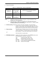
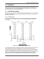
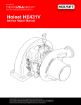
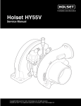
EPSON TERMINAL PRINTER EPSON Stylus Color 300 SERVICE MANUAL EPSON 4007996 All rights reserved. No part of this manual may be reproduced, stored in a retrieval system, or transmitted in any form or by any means, electronic, mechanical, photocopying, recording, or otherwise, without the prior written permission of SEIKO EPSON CORPORATION. The contents of this manual are subject to change without notice. All effort have been made to ensure the accuracy of the contents of this manual. However, should any errors be deteced, SEIKO EPSON would greatly appreciate being informed of them. The above not withstanding SEIKO EPSON CORPORATION can assume no responsibility for any errors in this manual or the consequences thereof. EPSON is a registered trademark of SEIKO EPSON CORPORATION. General Notice: Other product names used herein are for identification purpose only and may be trademarks or registered trademarks of their respective owners. EPSON disclaims any and all rights in those marks. Copyright © 1996 SEIKO EPSON CORPORATION. Printed in Japan. PRECAUTIONS Precautionary notations throughout the text are categorized relative to 1)Personal injury and 2) damage to equipment. DANGER Signals a precaution which, if ignored, could result in serious or fatal personal injury. Great caution should be exercised in performing procedures preceded by DANGER Headings. WARNING Signals a precaution which, if ignored, could result in damage to equipment. The precautionary measures itemized below should always be observed when performing repair/maintenance procedures. DANGER 1. ALWAYS DISCONNECT THE PRODUCT FROM THE POWER SOURCE AND PERIPHERAL DEVICES PERFORMING ANY MAINTENANCE OR REPAIR PROCEDURES. 2. NOWORK SHOULD BE PERFORMED ON THE UNIT BY PERSONS UNFAMILIER WITH BASIC SAFETY MEASURES AS DICTATED FOR ALL ELECTRONICS TECHNICIANS IN THEIR LINE OF WORK. 3. WHEN PERFORMING TESTING AS DICTATED WITHIN THIS MANUAL, DO NOT CONNECT THE UNIT TO A POWER SOURCE UNTIL INSTRUCTED TO DO SO. WHEN THE POWER SUPPLY CABLE MUST BE CONNECTED, USE EXTREME CAUTION IN WORKING ON POWER SUPPLY AND OTHER ELECTRONIC COMPONENTS. WARNING 1. REPAIRS ON EPSON PRODUCT SHOULD BE PERFORMED ONLY BY AN EPSON CERTIFIED REPAIR TECHNICIAN. 2. MAKE CERTAIN THAT THE SOURCE VOLTAGES IS THE SAME AS THE RATED VOLTAGE, LISTED ON THE SERIAL NUMBER/RATING PLATE. IF THE EPSON PRODUCT HAS A PRIMARY AC RATING DIFFERENT FROM AVAILABLE POWER SOURCE, DO NOT CONNECT IT TO THE POWER SOURCE. 3. ALWAYS VERIFY THAT THE EPSON PRODUCT HAS BEEN DISCONNECTED FROM THE POWER SOURCE BEFORE REMOVING OR REPLACING PRINTED CIRCUIT BOARDS AND/OR INDIVIDUAL CHIPS. 4. IN ORDER TO PROTECT SENSITIVE MICROPROCESSORS AND CIRCUITRY, USE STATIC DISCHARGE EQUIPMENT, SUCH AS ANTI-STATIC WRIST STRAPS, WHEN ACCESSING INTERNAL COMPONENTS. 5. REPLACE MALFUNCTIONING COMPONENTS ONLY WITH THOSE COMPONENTS BY THE MANUFACTURE; INTRODUCTION OF SECOND-SOURCE ICs OR OTHER NONAPPROVED COMPONENTS MAY DAMAGE THE PRODUCT AND VOID ANY APPLICABLE EPSON WARRANTY. PREFACE This manual describes basic functions, theory of electrical and mechanical operations, maintenance and repair procedures of EPSON Stylus Color 300. The instructions and procedures included herein are intended for the experienced repair technicians, and attention should be given to the precautions on the preceding page. The chapters are organized as follows: CHAPTER 1. PRODUCT DESCRIPTIONS Provides a general overview and specifications of the product. CHAPTER 2. OPERATING PRINCIPLES Describes the theory of electrical and mechanical operations of the product. CHAPTER 3. TROUBLESHOOTING Provides the step-by-step procedures for troubleshooting. CHAPTER 4. DISASSEMBLY AND ASSEMBLY Describes the step-by-step procedures for disassembling and assembling the product. CHAPTER 5. ADJUSTMENTS Provides Epson-approved methods for adjustment. CHAPTER 6. MAINTENANCE Provides preventive maintenance procedures and the lists of Epson-approved lubricants and adhesives required for servicing the product. APPENDIX Provides the following additional information for reference: • Connector pin assignments • Electric circuit boards components layout • Exploded diagram • Electrical circuit boards schematics REVISION SHEET Revision A Issued July 2, 1997 Contents First issue TABLE OF CONTENTS CHAPTER 1.PRODUCT DESCRIPTIONS CHAPTER 2.OPERATION PRINCIPLES CHAPTER 3.DISASSEMBLY AND ASSEMBLY CHAPTER 4.ADJUSTMENT CHAPTER 5.TROUBLESHOOTING CHAPTER 6.MAINTENANCE APPENDIX CHAPTER 1 PRODUCT DESCRIPTIONS 1.1 FEATURES ...................................................................................... 1-1 1.2 SPECIFICATIONS ........................................................................... 1-2 1.2.1 Printing Specifications.......................................................... 1-2 1.2.2 Software Specifications ........................................................ 1-3 1.2.3 Paper Handling ...................................................................... 1-4 1.2.4 Paper Specifications ............................................................. 1-4 1.2.5 Printable Area ........................................................................ 1-6 1.2.6 PG Adjust Lever Setting........................................................ 1-7 1.2.7 Paper Select Lever Setting ................................................... 1-7 1.2.8 Ink Cartridge Specification ................................................... 1-8 1.2.9 Electrical Specifications ....................................................... 1-9 1.2.10 Environmental Conditions .................................................. 1-9 1.2.11 Reliability............................................................................ 1-10 1.2.12 Acoustic Noise................................................................... 1-10 1.2.13 Safety Approvals................................................................ 1-10 1.2.14 CE Marking......................................................................... 1-10 1.2.15 Physical Specifications..................................................... 1-11 1.3 INTERFACE SPECIFICATION ...................................................... 1-12 1.4 OPERATIONS................................................................................ 1-12 1.4.1 Control Panel ....................................................................... 1-12 1.4.1.1 Buttons....................................................................... 1-12 1.4.1.2 LED Indicators ........................................................... 1-14 1.5 MAIN COMPONENTS ................................................................... 1-15 1.5.1 Printer Mechanism .............................................................. 1-15 1.5.2 Main Control Board (C224 MAIN Board)............................ 1-15 1.5.3 Power Supply Unit (C160 PSB/PSE Board)....................... 1-15 1.5.4 Housing ................................................................................ 1-15 Chapter 1 Product Descriptions 1.1 FEATURES The EPSON Stylus Color 300 printer is a color ink jet printer that comes with standard four colors (Black and CMY) printhead. The major features of this printer are: Standard four-colors printing. Both black and color (CMY) print nozzles are built in one-piece printhead. High-quality color printing 360 dpi (Horizontal/Vertical) printing and semi-720 dpi (Vertical only) printing High-speed printing 200 CPS at 10CPI (Pica) text printing in Black color. Standard Bi-directional Parallel Interface (IEEE1284 Nibble mode) Rev. A 1-1 EPSON Stylus Color 300 Service Manual 1.2 SPECIFICATIONS This section describes the product specifications for EPSON Stylus Color 300. 1.2.1 Printing Specifications Print system: Nozzle configuration: On-demand ink jet printer Black: 31 nozzles (11 nozzles x 2 columns and 10 nozzles x 1 column) Color: 11 nozzles / color 16/360" (1.1289mm) 104/360" (7.3378mm) 16/360" (1.1289mm) 104/360" (7.3378mm) #31 #M11 #C11 #B30 #Y11 1/60" (0.4233mm) 1/180" (0.1411mm) Print direction (Paper feed) 1/60" (0.4233mm) #29 #B3 #B1 #M1 #C1 1/180" (0.1411mm) 1/180" (0.1411mm) 1/180" (0.1411mm) #B2 #Y1 16/360" (1.1289mm) Viewed from the back of the printhead Figure 1-1. Printhead Nozzle Configuration Print direction: Bi-directional printing with logical-seeking Print speed: Text: 200 CPS (LQ/10CPI in Black color) Graphics: 20 IPS (at 360DPI) Printable column: Text: 80 columns (10CPI) Graphics: 2880 dot (at 360DPI) Character Table: Typeface: No table and include only the following characters: Alphabet [A to Z] (code 41H ~ 5AH) Number [0 to 9] (code 30H ~ 39H) SPACE (code 20H) Symbol [#] (code 23H) Bitmap LQ / EPSON Courier (10CPI) Input data buffer: 25Kbyte 1-2 Rev. A Chapter 1 Product Descriptions 1.2.2 Software Specifications Printer Language: Exclusive control codes for EPSON Stylus Color 300 EPSON Remote Command Control Code: <Character mode> General operation: Paper feeding: Carriage operation EEPROM Control <Graphics mode> General operation: Paper feeding: Carriage operation: Page formatting: Print position control: Spacing: Graphics: Color control: Note) ESC @ FF LF CR ESC | Initialize printer Uni-directional printing CSF Mode control Form feed Line feed Line spacing Carriage return Page length Top/Bottom margin Horizontal print position Vertical print position Define unit Graphics mode Raster graphics Printing color ESC @ ESC U ESC EM FF LF ESC + CR ESC (C ESC (c ESC $, ESC ¥ ESC (V, ESC (v ESC (U ESC (G ESC . (∗1) ESC r (∗2) EPSON Stylus Color 300 requires the specific printer driver for proper printing operation and control, and use of other printer driver could result in improper printing. ∗1: ∗2: Rev. A Initialize printer Form feed Line feed Carriage return Works only with unique parameters. It works only as a print buffer select command. 1-3 EPSON Stylus Color 300 Service Manual 1.2.3 Paper Handling Feeding method: Paper path: Line spacing: Paper feeding speed: Friction feed with built-in ASF Rear-top entrance / Front eject 1/6 inch or programmable in 1/360 inch minimum increments. 102 mS (at 1/6 inch paper feed pitch) 1.2.4 Paper Specifications Cut sheet Size: Table 1-1. Paper Size - Cut Sheet Type A4 LETTER B5 LEGAL Statement Executive Thickness: Weight: Quality: Width 210 mm (8.3”) 216 mm (8.5”) 182 mm (7.2”) 216 mm (8.5”) 139.7 mm (5.5”) 184.2 mm (7.25”) Length 297 mm (11.7”) 279 mm (11.0”) 257 mm (10.1”) 356 mm (14.0”) 215.9 mm (8.5”) 266.7 mm (10.5”) 0.08 ~ 0.11 mm (0.003 ~ 0.004”) 64 ~ 90 g/m² (17 ~ 24 lb.) Plain paper, Recycled paper, EPSON special medias Envelope Size: Table 1-2. Paper Size - Envelope Type No.10 DL Thickness: Weight: Quality: Width 241 mm 1 (9 /2”) 220 mm (8.7”) Length 104.8 mm 1 (4 /8”) 110 mm (4.3”) 0.16 ~ 0.52 mm (0.006 ~ 0.020”) 45 ~ 90 g/m² BOND paper, Plain paper, Airmail Note) ∗Envelope printing is allowed only under normal temperature/humidity condition. ∗Set the longer side of envelope horizontally at setting. 1-4 Rev. A Chapter 1 Product Descriptions Others Size: Table 1-3. Paper Size - Special Media Type Transparency (A4) Transparency (LETTER) Glossy Paper (A4) Glossy Paper (LETTER) Index Card (A6 size) Quality: Thickness: Note) Rev. A Width 210 mm (8.3”) 216 mm (8.5”) 210 mm (8.3”) 216 mm (8.5”) 105 mm (4.1”) Length 297 mm (11.7”) 279 mm (11.0”) 297 mm (11.7”) 279 mm (11.0”) 148 mm (5.8”) Exclusive transparency/Glossy Paper 0.23 mm (0.0091”) for Index Card Set the paper thickness lever to “THICK PAPER” position for index card printing. 1-5 EPSON Stylus Color 300 Service Manual 1.2.5 Printable Area The maximum printable area with each type of paper is summarized in table below. Table 1-4. Printable Area Type A4 LETTER LEGAL A6 B5 Statement Executive No.10 DL PW (typ.) 210 mm (8.3”) 216 mm (8.5”) 216 mm (8.5”) 105 mm (4.1”) 182 mm (7.2”) 139.7 mm (5.5”) 184.2 mm (7.25”) 241 mm (9.5”) 220 mm (8.7”) PL (typ.) 297 mm (11.7”) 279 mm (11.0”) 356 mm (14”) 148 mm (5.8”) 257 mm (10.1”) 215.9 mm (8.5”) 266.7 mm (10.5”) 105 mm (4.1”) 110 mm (4.3”) LM (Min.) 3.0 mm (0.12”) ⇑ RM (Min.) 3.0 mm (0.12”) ⇑ TM (Min.) 3.0 mm (0.12”) ⇑ BM (Min.) 14.0 mm (0.55”) ⇑ ⇑ ⇑ ⇑ ⇑ ⇑ ⇑ ⇑ ⇑ ⇑ ⇑ ⇑ ⇑ ⇑ ⇑ ⇑ ⇑ ⇑ ⇑ ⇑ ⇑ ⇑ 33.8 mm (1.33”) 13.8 mm (0.54”) ⇑ ⇑ ⇑ ⇑ ⇑ PW CUT SHEET RM PL TM LM BM Printable Area PW LM RM PL TM ENVELOPE BM Printable Area Figure 1-2. Printable Area 1-6 Rev. A Chapter 1 Product Descriptions 1.2.6 PG Adjust Lever Setting The paper-gap (PG); a space between the printhead nozzle surface annd the paper surface, can be adjusted to the appropriate level by the PG adjust lever which located underneath the printer cover. Table 1-5. PG Adjust Lever Setting Paper Type Cut Sheet Envelope Lever Position Front (“0” position) Rear (“+” position) Gap Setting 0 mm +0.62 mm 1.2.7 Paper Select Lever Setting The built-in ASF is equipped with the adjust lever and the position of lever should be set to appropriate position according to the type of paper used for the printing. Table 1-6. Paper Select Lever Setting Paper Feeding Source Select Lever Position ASF Thick Normal Manual Thick Insertion Normal Paper Type Cut Sheet Envelope No OK OK No OK No OK No Paper Thickness Lever (Forward position: Normal Backward position: Thick paper) Paper Thickness Lever (Locate underneath the printer cover) (Forward position: "0" Normal Backward position: "+" Envelopes) Figure 1-3. PG Adjust Lever and Paper Select Lever Rev. A 1-7 EPSON Stylus Color 300 Service Manual 1.2.8 Ink Cartridge Specification Type: Color: Exclusive cartridge Black and CMY (Cyan, Magenta, Yellow) Print capacity: 220 pages 450 pages Validity: 2 years (in sealed package) 6 months (out of package) Storage conditions: Transit (Package): Weight: Dimensions: 69.3 gram (internal ink amount = 41.1g) 45.9 (W) × 56.5 (D) × 38.5 ±0.3 (H) mm (360 DPI / 5% duty for each color on A4) (ISO/IEC10561 LETTER pattern at 360 DPI monochrome printing on A4) 56.5 mm -30 ∼ 60 °C (120 hours or less at 60 °C and a month or less at 40 °C) Storage (Package): -30 ∼ 40 °C (A month or less at 40 °C) After installation: -20 ∼ 40 °C (A month or less at 40 °C) 38.5 mm 45.9 mm Yellow Magenta Cyan Black Figure 1-4. Ink Cartridge 1-8 Rev. A Chapter 1 Product Descriptions 1.2.9 Electrical Specifications Table 1-7. Electrical Specification Item Rated Voltage Input Voltage Range Rated Frequency Range Input Frequency Range Rated Current Power Consumption Insulation Resistance 120V Version 120 VAC 103.5 ∼ 132 V 220 ∼ 240V Version 220 ∼ 240 VAC 198 ∼ 264 V 50 ∼ 60 Hz 50 ∼ 60 Hz 49.5 ∼ 60.5 Hz 49.5 ∼ 60.5 Hz 0.5 A (Max. 0.5 A) Approx. 15 W (ISO/IEC10561 LETTER pattern) 0.3 A (Max. 0.3 A) Approx. 15 W (ISO/IEC10561 LETTER pattern) Energy Star Compliant 10 MΩ, Min. (applying 500 VDC between AC line and chassis) AC 1500 Vrms for 1 min. (between AC line and chassis) 10 MΩ, Min. (applying 500 VDC between AC line and chassis) AC 1000 Vrms for 1 min. or AC 1200 Vrms for 1 sec. (between AC line and chassis) Dielectric Strength 1.2.10 Environmental Conditions Table 1-8. Environmental Conditions Condition Temperature Humidity Shock Resistance Vibration Resistance Note) ∗1: ∗2: ∗3: Operating 10 ∼ 35 °C ∗3 20 ∼ 80 % ∗2/3 1G (within 1 ms) 0.15G Non operating -20 ∼ 60 °C ∗1 5 ∼ 85 % ∗1/2 2G (within 2 ms) ∗1 0.50G ∗1 Applicable when the unit is in a shipping container. Without condensation. The unit should be operated within the range shown in figure below. Humidity (%) 80 55 20 10 27 35 Temperature (°C) Figure 1-5. Temperature and Humidity Range Rev. A 1-9 EPSON Stylus Color 300 Service Manual 1.2.11 Reliability Total Print Volume: Printhead Life: 10,000 pages (A4 / LETTER) 1000 million dots / nozzle (Black and CMY) 1.2.12 Acoustic Noise Level: Approx. 45 dB(A) (according to ISO7779) 1.2.13 Safety Approvals Table 1-9. Safety Approvals Item Safety Standard EMI 120V Version UL1950 with D3 CSA C22.2 No.950 with D3 FCC part 15 subpart B class B CSA C108.8 class B 220 ∼ 240V Version EN 60950 (TÜV, NEMKO) EN55022 (CISPR Pub.22) class B AS/NSZ 3548 class B 1.2.14 CE Marking [220 ~ 240V Version only] Low Voltage Directive 73/26/EEC: EMC Directive89/336/EEC: 1-10 EN60950 EN55022 Class B EN61000-3-2 EN61000-3-3 EN50082-1 IEC801-2 IEC801-3 IEC801-4 Rev. A Chapter 1 Product Descriptions 1.2.15 Physical Specifications Dimensions: 397 (W) × 319 (D) × 269 (H) mm (operating condition) Weight: 3.9 Kg (exclude the printhead and the ink cartridge) 269 mm 319 mm m 397 m Figure 1-6. Dimensions Rev. A 1-11 EPSON Stylus Color 300 Service Manual 1.3 INTERFACE SPECIFICATION Refer to the service manual of EPSON Stylus Color 200 / Stylus 200 for details. 1.4 OPERATIONS This section describes the basic operation of the printer. 1.4.1 Control Panel The control panel is equipped with two non-lock type push buttons and three LED indicators, and operations of each button and LED indicator are described below. Buttons LOAD/EJECT CLEANING LED Indicators PAPER OUT (Red) INK OUT (Red) POWER (Green) Figure 1-7. Control Panel 1.4.1.1 Buttons Normal Operation Table 1-10. Control Panel - Normal Operations Button LOAD/EJECT Operation Pressed less than 3 sec. Function • Loads or ejects the paper. • When the carriage is at the ink-cartridge replace position, return the carriage to the home position. Pressed for 3 sec. • Starts the ink-cartridge replace operation and the carriage moves to the ink-cartridge replace position. CLEANING Pressed less than 3 sec. • Starts the cleaning operation. • When the printer is in “Ink Low”, “Ink Out” or “No ink cartridge” status, the printer moves the carriage to the ink-cartridge replace position. Pressed for 3 sec. • When the carriage is at the ink-cartridge replace position, return the carriage to the home position. 1-12 Rev. A Chapter 1 Product Descriptions Power-On Operation Table 1-11. Control Panel - Power-on Operations Button st [1 button] Hold down at power on CLEANING LOAD/EJECT LOAD/EJECT + CLEANING Note) ∗1: ∗2: nd [2 button] Pressed within 3 sec. after power on. ∗2 --------LOAD/EJECT + CLEANING ∗1 Function The printer perform the following after performing the control panel operation in left column. Self-printing test Status printing EEPROM Initialization Holds down the specified buttons for 10 sec. or more until INK OUT and PAPER OUT LED starts blinking. After the power on, INK OUT and PAPER OUT LED starts blinking and continue for about 3 sec. “Press within 3 sec. after power on” means to press nd 2 buttons while these LED are blinking. Self-test printing:The printer prints the self check test pattern. The printer prints a page at a time and pauses between each page. When the printer is in pause state, press LOAD/EJECT button to resume printing and turn the power off to cancel the self-test printing. Status printing: The printer prints; Firmware version, ink counter value and a nozzle check pattern. The printer goes to a pause state after print one page. To cancel the status printing, turn the power off while the printer is in pause state. EEPROM Initialization: Initialize the following addresses of the EEPROM (refer to the EEPROM address map table in Appendix.) 1AH: 1BH: 2CH/2DH: 70H - 73H: 78H - 7BH: Rev. A Interface selection (00H: Auto) Interface Wait Time (02H: 2 sec.) Counter A (Protect counter) (00H) 4-color head non-installation time (00H) Power Off Timer (00H) 1-13 EPSON Stylus Color 300 Service Manual 1.4.1.2 LED Indicators The LED indicators of the control panel shows the various printer status as below. Table 1-12. Control Panel - LED Status Indications Status Ink low (printable) Ink out (not printable) Paper out Paper jam No ink cartridge No printhead POWER ON ON ON ON ON ON INK OUT Blink ON --------ON Blink (Fast) ----- PAPER OUT --------ON Blink ------------- High Blink Blink (Fast) ON Highest Blink (Fast) • Replacing head/ink cartridge • Printing • During ink sequence Blink EEPROM initialization Button(s) is pressed at power on ON Blink • Carriage control error • Fatal error Blink Blink Blink (Fast) ON Maintenance request Blink (Fast) Blink (Fast) 1-14 Priority Low Medium Rev. A Chapter 1 Product Descriptions 1.5 MAIN COMPONENTS The EPSON Stylus Color 300 is composed of the following main components: Printer mechanism Main control board (C224 MAIN Board) Power Supply Unit (C160 PSB/PSE Board : Same as EPSON Stylus Color 200 / Stylus 200) Control Panel Housing 1.5.1 Printer Mechanism The mechanical design of printer mechanism for EPSON Stylus Color 300 is basically the same with EPSON Stylus Color 200/Stylus 200, and is equipped with the detachable 4colors one-piece printhead unit. 1.5.2 Main Control Board (C224 MAIN Board) The main control board (C224 MAIN board) is controlled by the M37721S2BFP 16bit CPU (IC2) which driven with 25MHz clock speed. The E05B49KA custom gate array (IC1) controls the memories (ROM and RAM), a built-in parallel interface circuit and the printhead drive voltage generation circuit. 1.5.3 Power Supply Unit (C160 PSB/PSE Board) The power supply unit of EPSON Stylus Color 300 is exactly the same with EPSON Stylus Color 200/Stylus 200. 1.5.4 Housing In accordance with the control panel design change, the upper housing is also changed from EPSON Stylus Color 200/Stylus 200. Rev. A 1-15 CHAPTER 2 OPERATING PRINCIPLES 2.1 OVERVIEW ...................................................................................... 2-1 2.1.1 PRINTER MECHANISM ......................................................... 2-1 2.1.1.1 Printhead Unit .............................................................. 2-1 Chapter 2 Operating Principles 2.1 OVERVIEW Since most of the printer mechanism design and the electrical circuits of EPSON Stylus Color 300 remains the same with EPSON Stylus Color 200/Stylus 200, this chapter only describes the difference in the printer mechanism. 2.1.1 PRINTER MECHANISM Based on the printer mechanism for EPSON Stylus Color 200/Stylus 200, a newly designed one-piece 4-color printhead is incorporated on EPSON Stylus Color 300. This section only describes the printhead. 2.1.1.1 Printhead Unit The printhead unit for EPSON Stylus Color 300 is a new design printhead and has both black and color (CMY) nozzles in one unit. The nozzle arrangement of the printhead is shown below. 16/360" (1.1289mm) 104/360" (7.3378mm) 16/360" (1.1289mm) 104/360" (7.3378mm) #31 #M11 #C11 #B30 #Y11 1/60" (0.4233mm) 1/180" (0.1411mm) Print direction (Paper feed) 1/60" (0.4233mm) #29 #B3 #B1 #M1 #C1 1/180" (0.1411mm) 1/180" (0.1411mm) 1/180" (0.1411mm) #B2 #Y1 16/360" (1.1289mm) Viewed from the back of the printhead Figure 2-1. Printhead (Nozzle Configuration) To compensate the electrical characteristics variation of the piezo-electric element used on each printhead unit, the electrical characteristics is measured at the factory and the measured characteristic level is designated as an ID of the printhead. The ID of printhead is recorded on each printedhead by changing a signal line pattern connection on the head drive circuit of the printhead. The main control circuit detect the status of this signal line and determines the printhead ID and adjust the head drive voltage level according to the printhead ID. Therefore, no head ID registration to EEPROM is required on this printer. Rev. A 2-1 CHAPTER 3 DISASSEMBLY AND ASSEMBLY 3.1 OVERVIEW ...................................................................................... 3-1 3.1.1 Upper Case Removal............................................................. 3-1 3.1.2 C224 MAIN Board Removal .................................................. 3-2 Chapter 3 Disassembly and Assembly 3.1 OVERVIEW This section describes procedures for disassembling and assembling the main components of EPSON Stylus Color 300. Since the most of components are the same with EPSON Stylus Color 200/Stylus 200, this manual only describes procedures unique to this printer. 3.1.1 Upper Case Removal 1. Remove the sheet guide from the printer. 2. Move the paper select lever to the backward position, then remove one screw (CBP/M2x6) securing a knob to the paper select lever. 3. Open the printer cover, then remove five screws (one CBB/M4x6 and four CBP/M4x12) securing the upper case to the bottom case. 4. Remove the upper case by lifting it upward. Knob (paper select lever) CBP (M4x12) CBP (M2x8) Printer Cover CBB (M3x8) Upper Case Figure 3-1. Upper Case Removal Rev. A 3-1 EPSON Stylus Color 300 Service Manual 3.1.2 C224 MAIN Board Removal 1. Remove the upper case. (See Section 3.1.1). 2. Remove five screws (CBB/M3x6); four screws fixing the shield plate directly to the C224 MAIN Board and one screw fixing the metal bracket to the shield plate. 3. Disconnect all cables connected to the C224 MAIN Board and remove the C224 MAIN Board. CBB (M3x6) CBB (M3x6) Bracket SHIELD PLATE C224 MAIN BOARD Figure 3-2. C224 MAIN Board Removal 3-2 Rev. A CHAPTER 4 ADJUSTMENT 4.1 OVERVIEW ...................................................................................... 4-1 4.1.1 Adjustment Tools .................................................................. 4-1 4.1.2 Applicable Repair .................................................................. 4-1 4.1.3 Adjustment Program ............................................................. 4-2 4.1.3.1 Zig-Zag Adjustment ..................................................... 4-2 4.1.3.2 Bi-D Adjustment........................................................... 4-2 4.1.3.3 Head Angle Adjustment ............................................... 4-2 4.1.3.4 RESET Fucntion .......................................................... 4-3 Chapter 4 Adjustment 4.1 OVERVIEW This section describes procedures for adjustments which required when the printer is disassembled and assembled for repair. CAUTION Once the ink cartridge is removed from the printer before ink-end, never re-use it. For adjustment and testing, always replace the ink cartridge to new one designed exclusively for service: Description: Code: 4.1.1 Adjustment Tools The table below lists the tools required to make adjustment on EPSON Stylus Color 300. Table 4-1. Tools for Adjustment Tool Thickness Gauge Set #F518 *1 Adjustment Program Name: CLR300.EXE Code B776702201 ----- Applicable Adjustment • Platen Gap Adjustment • • • • Head Angle Adjustment Bi-D Adjustment Zig-Zag Alignment Adjustment RESET function for: *Ink counter *Initial charge flag *Protect counter (Waste ink counter) 4.1.2 Applicable Repair An appropriate adjustment have to be made according to the type of repair performed. Table 4-2. Applicable Adjustment Repair C224 MAIN board is replaced *1 Printhead is replaced *2 Printer mechanism is replaced *2 • CR Motor or timing belt is replaced • Carriage assembly is disassembled Note) *1: *2: Rev. A • • • • • • • Applicable Adjustment Zig-Zag Alignment Adjustment Bi-D Adjustment Zig-Zag Alignment Adjustment Head Angle Adjustment Zig-Zag Alignment Adjustment Bi-D Adjustment Bi-D Alignment Replace the ink cartridge and the waste ink pad to new one and reset ink counter and protect counter. Replace the ink cartridge to new one and reset initial charge flag and ink counter. 4-1 EPSON Stylus Color 300 Service Manual 4.1.3 Adjustment Program The adjustment program CLR300.EXE is specifically designed for use with the EPSON Stylus Color 300 and the following adjustments can be made with this program. Zig-Zag Adjustment Bi-D Adjustment Head Angle Adjustment Reset operation To start making adjustment with the program, execute the program on the PC that connected to the target printer and follow the instruction shown on the PC monitor. CAUTION Since the mechanism design is the same with the EPSON Stylus Color 200, refer to the service manual for EPSON Stylus Color 200, at Chapter 4 Adjustment, for the detail procedures. 4.1.3.1 Zig-Zag Adjustment This adjustment is required to specify the print timing control parameter that determines the ink injection timing for each nozzle. If the adjustment is wrong, a vertical line printed within single print pass become jagged. Verify the check pattern printed by the program and specify the parameter until the check pattern become aligned most properly. 4.1.3.2 Bi-D Adjustment This adjustment is required to specify the control parameter that determines the print timing in bi-directional printing. If the adjustment is wrong, the print position at each print direction is not aligned each other. Verify the check pattern printed by the program and specify the parameter until the check pattern become aligned most properly. 4.1.3.3 Head Angle Adjustment This adjustment is required when the printhead is replaced to new one. Every dot line (raster) need to be parallel each other and the angle of the printhead, at which the printhead is fixed on the carriage assembly, determines a parallel level. The program prints the check pattern to judge the angle of printhead, and is the angle is not correct, move the head angle adjust lever located at the right hand side of the carriage assembly to a position with which the printed pattern become parallel. 4-2 Rev. A Chapter 4 Adjustment 4.1.3.4 RESET Fucntion Since various ink system management information are stored in EEPROM on the main board, the information integrity need to be kept even after the combination of the printer mechanism and the main board is altered. Therefore, if any of the component (main board, printer mechanism or the printhead) is replaced to new one, reset the appropriate information (counter value or flag). Table 4-3. RESET Operation Type of Repair C224 MAIN board is replaced Printer Mechanism is replaced Printhead is replaced Rev. A • • • • • • • • • • Required Operation Ink Cartridge replacement Waste ink pad replacement [RESET] Ink counter [RESET] Protect counter [RESET] Initial charge flag [RESET] Ink counter Ink Cartridge replacement [RESET] Initial charge flag [RESET] Ink counter Ink Cartridge replacement 4-3 CHAPTER 5 TROUBLESHOOTING 5.1 OVERVIEW ...................................................................................... 5-1 5.1.1 Unit Repair - C224 MAIN Board ............................................ 5-1 Chapter 5 Troubleshooting 5.1 OVERVIEW Since the printer mechanism and the power supply unit are remains the same with EPSON Stylus Color 200/Stylus 200, this chapter describes only the checkpoints on the main control circuit; C224 MAIN Board. 5.1.1 Unit Repair - C224 MAIN Board The table below provides various symptom, likely causes and checkpoint, relating to the C224 MAIN Board. Symptom Printer does not operate at all. Condition CPU does not operate. ASIC does not operate. Rev. A Cause Reset IC (IC9) is defective Checkpoint Check the signal waveform at pin 6 of IC9: Solution Replace IC9 Oscillator (CR2) or CPU (IC2) is defective Is the signal waveform output from CR2 correct at pin 37/38? Correct: Replace IC2 Incorrect: Replace CR2 ASIC (IC1) is defective Is the signal waveform at pins 52 of IC1 correct? Replace IC1 5-1 EPSON Stylus Color 300 Service Manual Symptom Self-test printing is abnormal. Carriage does not operate normally. 5-2 Condition No printing. Drive signals are not output correctly. Cause PWM signal is not output. Checkpoint Is PWM signal waveform correct at pin 140 of IC1? Solution Replace IC1 Head drive voltage generation circuit does not operate. Check waveform of the signal VO: Replace any defective components: Q1/2/4/7/8 or QM1/3/4/5/6/7/8 CPU (IC2) is defective Is the signal waveform correct at pin 5/6 of IC2? Replace IC2 CR Motor driver (IC8) is defective Is the signal waveform correct at pin 3/6/18/21 of IC8? Correct: Replace CR Motor Incorrect: Replace IC9 Rev. A Chapter 5 Troubleshooting Symptom Paper does not advance normally. Rev. A Condition Drive signals are not output correctly. Cause CPU (IC2) is defective Checkpoint Is the signal waveform correcr at pin 7/8 of IC2? Solution Replace IC2 PF Motor driver (IC16) is defective Is the signal waveform correct at pin 14/17/20/23 of IC16? Correct: Replace PF Motor Incorrect: Replace IC16 5-3 CHAPTER 6 MAINTENANCE 6.1 OVERVIEW ...................................................................................... 6-1 6.1.1 Maintenance Request............................................................ 6-1 Chapter 6 Maintenance 6.1 OVERVIEW This section describes the maintenance points and the procedures specific for EPSON Stylus Color 300. WARNING If ink gets in your eyes, flush them immediately with water and seek medical attention. Disconnect the printer from the power source when you clean inside the printer. CAUTION Once the ink cartridge is removed from the printer before ink-end, never re-use it. For adjustment and testing, use the ink cartridge designed exclusively for service: Description: Code: 6.1.1 Maintenance Request The printer counts total amount of ink drained to the waste ink pad and this information is stored in the EEPROM on the main board, as the protect counter A value for ink system operation management. When the counter value reaches the predetermined value, the printer detects it as “Maintenance Request” error and displays the error status with the control panel LED indicators (see Table 1-12 at Chapter 1, Section 1.4.1.2 LED Indicators). When this error displayed, replace the waste ink pad to new one and reset the counter value with the procedure shown below. Turn the printer ON while hold down the buttons: LOAD/EJECT CLEANING "POWER" LED continue for 3 seconds "INK OUT" LED "PAPER OUT" LED Press the buttons within 3 seconds from power ON, and kept them pressed until "INK END", "PAPER OUT" LEDs starts blinking: LOAD/EJECT CLEANING "POWER" LED "INK OUT" LED "PAPER OUT" LED Figure 6-1. “Maintenance Request” Error Clear Operation Rev. A 6-1 APPENDIX A.1 OVERVIEW......................................................................................A-1 A.2 EEPROM Address Map..................................................................A-2 A.3 CIRCUIT DIAGRAM (C224 MAIN BOARD)....................................A-4 Appendix A.1 OVERVIEW The main board of EPSON Stylus Color 300 is C224 MAIN BOARD and each connector and its pin assignment are the same with the main board for EPSON Stylus Color 200. Therefore, refer to the service manual for EPSON Stylus Color 200 for the details. Rev. A A-1 EPSON Stylus Color 300 Service Manual A.2 EEPROM Address Map The table below shows the addresses of EEPROM and the contents stored at each address. Table A-1. EEPROM Address Address Data 00 - 01H 02H (Reserved) Market (Model) 03 - 11H Customized model name 12 - 13H 14 - 15H 16H Bi-D Adjustment data (Reserved) Fire period adjustment data (Reserved) EEPROM Status 17H 18H 19H • • • • 1AH Interface selection 1BH Interface wait time 1CH 1DH (Reserved) Reply printer status control data 1EH Non-smear print mode 1FH (Reserved) A-2 THICK paper direction Auto LF Print direction Network I/F mode Value ----0: World 1: Japan 2 - 4: Custom • Strings counter • Strings of model field for device ID -36 ≤ n ≤ +36 (unit: 1/1440 inch) -----4 ≤ n ≤ +10 (unit: 0.08sec.) ----00H: other: Bit 7: Used (once initialized) Not used (to be initialized) <Thick paper> 0: Index card (Portrait) 1: Envelope (Landscape) Bit 3: <Auto LF> 0: OFF 1: ON Bit 2: <Network I/F mode> 0: OFF 1: ON Bit 1/0: <Print direction> 0/0: Bi-D 0/1: Uni-D 1/1: Auto 00H: Auto 02H: Parallel I/F 03H: Serial I.F 02H: 2sec. 03H: 3sec. ----Bit 0: <function> 0: ON 1: OFF Bit 0: <function> 0: Normal 1: Non-smear print mode ----- Factory Default 00H 00H 00H *1 00H *1 00H 00H 82H 00H *2 02H *2 ----00H 00H ----- Rev. A Appendix Table A-2. EEPROM Address (continued) Address Data 20H 21H 22 - 23H 24 - 25H 26 - 27H CR Motor initial phase (Reserved) YMC Accumulated time Counter D Counter E (Initial charge flag) Counter R (Cap flushing counter) Ink status Counter A (Protect counter) Counter C (Number of power ON) Fire dot counter K (Black ) Fired dot counter Y (Yellow) Fired dot counter M (Magenta) Fired dot counter C (Cyan) (Reserved) Head vacuuming time A 28 - 29H 2A - 2BH 2C 2DH 2E - 2FH 30 - 35H 36 - 3BH 3C - 41H 42 - 47H 48 - 6BH 6C -6FH 70 - 73H 74 - 77H 78 - 7BH 4-color head uninstallation time (Reserved) Power off time 7CH 7DH 7EH 7FH (Reserved) VH adjust value (KR) VH adjust value (Vad-L) VH adjust value (Vad-H) Rev. A Value ----- 00H: 01H: Initial charge required Initial charge done Factory Default *1 ----00H 00H 00H 00H 00H 00H 00H 1 count = 1ng 00H 1 count = 1ng 00H 1 count = 1ng 00H 1 count = 1ng 00H ----0 to FFFFFFFFH (unit: 10 min.) Start from 1992/01/01 00:00 00H 01H 00H 00H 00H 00H *2 00H 00H *2 ----------------- 0 to FFFFFFFFH (unit: 10 min.) Start from 1992/01/01 00:00 ----0 to FFFFFFFFH (unit: 10 min.) Start from 1992/01/01 00:00 ----(10000 x KR) (1000 x VerrAD(L)) (1000 x VerrAD(H)) A-3 EPSON Stylus Color 300 Service Manual A.3 CIRCUIT DIAGRAM (C224 MAIN BOARD) A-4 Rev. A EPSON OVERSEAS MARKETING LOCATIONS EPSON AMERICA, INC. EPSON UK LTD. 20770 Madrona Ave. P.O. Box 2842 Torrance, CA 90509-2842 Phone:(800) 922-8911 Fax: (310) 782-5220 EPSON DEUTSCHLAND GmbH Campus 100, Mayland Avenue, Hemel Hempstead, Herts, HP2 7TJ, U.K. Phone:(+44) 01442 61144 Fax: (+44) 01442 227227 Zülpicher Straβe 6, 40549 Düsseldorf Germany Phone:(0211) 56030 Telex: 8584786 68 bis, rue Marjolin 92300, Levallois-Perret, France Phone:33.1.40.87.37.37 Telex: 610657 EPSON AUSTRALIA PTY. LTD. EPSON SINGAPORE PTE. LTD. 70 GIBBES STREET, CHATSWOOD 2067 NSW. Phone:2-9903-9000 Fax: 2-9903-9177 No.1 Temasek Avenue #36-00 Millenia Tower, Singapore 039192 Phone:(065) 33 77 911 Fax: (065) 33 41 185 EPSON HONG KONG LTD. EPSON TAIWAN TECHNOLOGY & TRADING LTD. EPSON FRANCE S.A. Rooms 4706-10, 47/F China Resources Bldg., 26 Harbour Road, Wanchai, Hong Kong Phone:2585-4300 Fax: 2827-7083 10F, No.287 Nanking E. Road, Sec.3, Taipei, Taiwan, R.O.C. Phone:(02) 717-7360 Fax: (02) 712-9164 EPSON ITALIA S.p.A. EPSON IBERICA S.A. V. le F. lli Casiraghi 427 20099 Sesto S. Giovanni MI, Italy Phone:2-262331 Fax: 2-2440750 EPSON PORTUGAL, S.A. Av. de Roma, 18-26 08290 Cerdanyola del Valles Barcelona, Spain Phone:582.15.00 Fax: 582.15.55 R. do Progresso, 471, 1° Perafita 4460 Matosinhos, Portugal Phone:(02) 996 14 02 Fax: (02) 996 14 11 SEIKO EPSON CORPORATION HIROOKA OFFICE / Imaging & Information Products Division 80 Harashinden, Hirooka Shiojiri-Shi, Nagano-Ken 399-07 Japan EPSON SEIKO EPSON CORPORATION