1
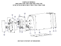
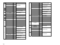
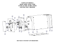
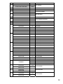
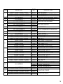
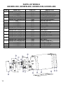
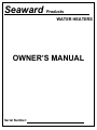
Seaward Products
WATER HEATERS
OWNER’S MANUAL
Serial Number:
IMPORTANT SAFETY INSTRUCTIONS
WARNING
When using electrical appliances, basic safety precautions to reduce the risk of fire, electrical
shock, or injury to persons should be followed, including:
1. READ ALL INSTRUCTIONS BEFORE USING THIS WATER HEATER.
2. This water heater must be grounded. Connect only to properly grounded source.
See “GROUNDING INSTRUCTIONS” found on Page 4, Item 7.
3. Install or locate this water heater only in accordance with the provided installation
instructions.
4. Use this water heater only for its intended use as described in this manual.
5. Do not use an extension cord set with this water heater. If no junction box is available
adjacent to the water heater, contact a qualified electrician to have one properly
installed.
6. As with any appliance, close supervision is necessary when used by children.
7. Do not operate this water heater if it has a damaged power supply line, if it is not
working properly, or if it has been damaged or dropped.
8. This water heater should be serviced only by qualified service personnel. Contact
nearest authorized service facility for examination, repair, or adjustment.
WARNING
This water heater is equipped with a heat exchanger. Extended engine coolant
circulation through the heater may result in excessively hot water.
This water heater tank and heat exchanger is made of aluminum. Some engine
manufacturers recommend that cooling system be flushed periodically. Caustic
chemicals are commonly used. DO NOT flush caustic chemicals (such as Nalcool)
through your system with the heat exchanger hooked up or damage WILL occur to
heater.
If flushing is required by your engine manufacturer, you must isolate heater from
this process. After system flushing is complete and neutralized, you can then re-plumb
heater. Make sure recommended automotive type premixed ethylene glycol coolants
such as Prestone, Xerex, or Peak are used for replacement. Damage that occurs to
heater due to chemical reaction by caustic chemicals IS NOT under warranty.
1
CAUTION
Hydrogen gas can be produced in a hot water system served by these heaters that
have not been used for a long period of time (generally 2 weeks or more.) Hydrogen gas is
extremely flammable. To reduce the risk of injury under these conditions, it is recommended
that the hot water faucet be opened for several minutes at the kitchen sink before using any
electrical appliance connected to the hot water system. If hydrogen is present, there will be
an unusual sound such as air escaping through the pipe as the water begins to flow. There
should be no smoking or open flame near the faucet at the time it is open.
Small amounts of electric currents may move to your boat through your shore cord,
causing galvanic damage to your water heater. To help prevent possible damage, a galvanic
isolator is recommended. Galvanic corrosion IS NOT covered under warranty.
ANODES
In a small number of instances tap water may have sufficient concentrations of
dissolved salts to cause corrosion of the heater tank. Anode rods preserve the life of a water
heater by corroding themselves so the water heater doesn't. These anode rods are easy to
install! Simply replace the drain plug with this product to protect the water heater tank.
Note:
DO NOT USE ZINC ANODES. THEY WILL NOT PREVENT
CORROSION TO YOUR HEATER TANK!!!!
If you live in an area known to have such water please contact our customer service
department at 562-699-7997 to order a Magnesium Anode.
Part No. 74556, Magnesium 4” Anode with ¾” thread to replace drain valve.
HOT WATER OUTLET
ANODE PART # 74556
REPLACES DRAIN
VALVE PART # 73123
P & T VALVE
DRAIN
***REMOVE DRAIN AND
REPLACE WITH ANODE
COLD WATER INLET
2
NOTICE
This temperature / pressure valve may weep during initial operation. This is normal.
The valve will seat itself with use. A drain hose should be installed at this valve directed into
bilge.
If the boat is connected to the dockside water system, make sure to turn off the system
at the dock when not attended. Also make sure a pressure regulator is used to control
pressure.
OPERATING INSTRUCTIONS
1.
2.
3.
4.
Fill water system and completely fill tank.
Locate and turn remote electrical switch to “ON”.
Turn switch to “OFF” position prior to draining water system.
The temperature / pressure valve may weep during initial operation. This is normal.
The valve will seat itself with use.
NOTE: DO NOT OPERATE HEATER WITHOUT ELEMENT BEING SUBMERGED IN WATER.
MAINTENANCE
1. Check heat exchanger lines for leaks at regular intervals. A leak in the system will
cause coolant loss and may damage engine.
2. Flush tank periodically to help prevent build-up of deposits.
3. Protect against damage from freezing temperatures (32° F or less)
Please review the following:
a) Drain tank by fully opening drain valve. Open T&P valve to help relieve vacuum
in tank. (See item 2 in exploded view)
b) It is recommended you winterize your fresh water system. First complete step 3a,
then follow instructions of your local supplier regarding chemicals to use and how
to use them.
CAUTION
If heater has been run without water and now fails to work, fill heater tank with water and push electric
reset button high limit switch under wire access cover before calling for service.
ENGINE COOLANT LINES
HEAT EXCHANGER TUBING
HOSE CLAMP
SAE J53Q TYPE "E" OR EQUIVALENT
5/8" I.D. HOSE
SAE "2" OR "3" OR EQUIVALENT
Figure 1
NOTE: Whether heat exchanger tubes are out the Front or Rear the same connection
information applies.
3
INSTALLATION
NOTE: DO NOT INSTALL THE WATER HEATER ON ITS SIDE OR UP SIDE DOWN.
1. Locate water heater at engine level as close to engine as possible.
2. Secure mounting brackets to structure with eight #12 minimum screws or ¼ - 20
minimum cap screws and nuts.
3. Connect cold water supply and hot water outlet to heater as marked, ½” N.P.T. fittings.
4. Connect heat exchanger system described in Figure 1. Make sure coolant system is
completely purged of air and full of coolant before operating.
5. Pressure temperature relief valve is factory installed. The pressure relief shall limit the
pressure to 127.5 PSI (879.3 KPA) minimum, 150 PSI (1034.2 KPA) maximum.
The valve must be oriented, provided with tubing, or otherwise installed so that
discharge can exit no more than 6 inches above, or at any distance below the structural
floor, and cannot contact any live electrical part.
Install replacement temperature and pressure protective equipment required by local
codes, but not less than a combination temperature and pressure relief valve certified
as meeting the requirements for relief valves and automatic gas shutoff devices for hot
water supply systems, ANSI Z21.22 by a nationally recognized testing laboratory that
maintains periodic inspection of production of listed equipment or materials.
6. Connect the electrical supply by a qualified electrician. The electrical supply shall be
permanent wiring, armored cable or conduit, per national electrical code NFPA 70, with
a minimum capacity of 1500 watts.
On 120 volt circuits, use a UL approved 15 amp circuit breaker. On 240 volt circuits,
use a 10 amp approved circuit breaker per leg.
7. GROUNDING INSTRUCTIONS: The supply ground shall be connected to the green
wire located in the water heater wiring compartment. Do not place switch in the
grounding circuit.
8. RESET INSTRUCTIONS: The heater is equipped with a high limit switch which can be
manually reset. If the limit switch activates, proceed as follows:
• Turn power off at main power panel or remote switch
• Remove wiring access cover
• Depress red button on high temperature limit switch
• Replace cover and turn power on
• If temperature limit switch reactivates, contact a Seaward Products
Authorized service center.
4
WIRING DIAGRAM FOR 120V
RESET
HIGH TEMP LIMIT SWITCH
BLACK
120 VAC
WHITE
GREEN
GROUND WIRE
FIXED TEMP CONTROL
THERMOSTAT
HEATER ELEMENT
120 VAC
WIRING DIAGRAM FOR 240V
HIGH TEMP LIMIT SWITCH
RESET
RED
240 VAC
BLACK
GREEN
GROUND WIRE
FIXED TEMP CONTROL
THERMOSTAT
HEATER ELEMENT
240 VAC
5
Winterizing Your Seaward Products Water Heater
Winterizing your fresh water system is an essential procedure that will maintain the life and longevity
of your Seaward Products water heater and fresh water tanks. To ensure that your fresh water
system has adequate protection for winter storage, use the following recommended winterizing
procedure.
Winterizing the Water Heater and Fresh Water System
1. Locate the fresh water tank drain valve or plug and allow the fresh water tanks to drain until
approximately 115% to 120% of the water heater capacity remains in the tanks.
Example: If water heater is 11 gallons = 12 to 13 gallons in fresh water tanks.
2. Treat the remaining fresh water left in the fresh water tanks with “Winterizing Chemicals”.
Winterizing chemicals are non-toxic antifreeze that is a propylene-glycol base and are safe for
potable water systems.
NOTICE
DO NOT USE THE TYPE OF ANTI-FREEZE THAT IS USED TO WINTERIZE
AUTOMOBILES. THIS IS NOT SAFE FOR POTABLE WATER SYSTEMS.
NOTICE
Antifreeze can be very corrosive to the anode rod. The result will be accelerated
deterioration of the rod and heavy sediment in the tank. If you intend to winterize by
adding antifreeze into the system and your water heater is equipped with an anode,
remove the anode rod (storing it for the winter) and replace it with a 3/4" male pipe
thread drain plug.
3. Turn off 120V or 240V AC power.
4. Turn on fresh water pump.
5. Open each faucet and water outlet one at a time until winterizing chemical is apparent at the
opening.
6. Turn off fresh water pump and leave all faucets and water outlets open over winter.
7. Locate the water heater drain and pressure relief valve and allow all water to drain from water
heater until empty. Leave water heater drain and pressure relief valve open over winter.
CAUTION
SPECIAL PRECAUTIONS MUST BE USED WHEN DRAINING AND FILLING AN ELECTRIC
WATER HEATER. ELECTRICITY MUST BE TURNED OFF BEFORE DRAINING AND
REFILLING WATER HEATER TANKS.
6
De-Winterizing the Water Heater and Fresh Water System
1. Close all faucets, water outlets, the water heater drain and pressure relief valve.
2. If during the winterizing procedure the anode was removed and replaced with a 3/4" male pipe
thread drain plug, remove the drain plug and replace with anode.
3. Fill fresh water tanks with fresh water approximately so that 115% to 120% of the water heater
capacity remains in the fresh water tanks.
Example: If water heater is 11 gallons = 12 to 13 gallons in fresh water tanks.
CAUTION
SPECIAL PRECAUTIONS MUST BE USED WHEN DRAINING AND FILLING AN ELECTRIC
WATER HEATER. ELECTRICITY MUST BE TURNED OFF BEFORE DRAINING AND
REFILLING WATER HEATER TANKS.
4. Turn on fresh water pump.
5. Open each faucet and water outlet one at a time until winterizing chemical is no longer
apparent at the opening. This allows the fresh water to flush the winterizing chemicals out of
the fresh water system.
6. Fill fresh water tanks to 100% capacity.
NOTICE
Seaward Products recommends that while filling the fresh water storage tanks that a
small amount of common household bleach be added to the fresh water system to
control the possible growth of algae. If an algae condition starts it is very difficult to
control.
Example: 1 oz of bleach for every 50 gallons of fresh water.
7. Fresh water system is now de-winterized and ready for use.
7
PARTS LIST MODELS
S300W & S350W
ITEM
MODEL NO.
PART NO.
1
2
3
ALL MODELS
ALL MODELS
ALL MODELS
S300W
S350W
S300W
S350W
ALL MODELS
S300W
S350W
ALL MODELS
ALL MODELS
ALL MODELS
ALL MODELS
ALL MODELS
ALL MODELS
ALL MODELS
ALL MODELS
ALL MODELS
ALL MODELS
80727
73127
73124
75586
74715
74563
74607
73129
73148
73171
73123
73145
75552
73290
80652
75553
74669
73146
73147
73330
4
5
6
7
8
9
10
11
12
13
14
15
16
17
DESCRIPTION
TANK ASSEMBLY
TEMPERATURE/PRESSURE VALVE
GASKET, HEATING ELEMENT
1250W HEATING ELEMENT
3000W HEATING ELEMENT
HIGH LIMIT SWITCH, 120V
HIGH LIMIT SWITCH, 240V
THERMOSTAT
PLATE, THERMOSTAT MOUNTING 120V
PLATE, THERMOSTAT MOUNTING 240V
DRAIN VALVE
SHIELD, WIRES
WRAP, WHITE
BACK PANEL, WHITE
FRONT PANEL, WHITE
BASE, WHITE
ACCESS, COVER WHITE
INSULATION, WRAP
INSULATION, FRONT
INSULATION, BACK
8
PARTS LIST MODELS
S600, S650, S700, S750, F600, F650, F700, F750
S1100, S1150, S1200, S1250, F1100, F1150, F1200, F1250
EXPLODED VIEW
SEE PAGE 10 FOR PART LIST BREAKDOWN
ITEM
1
PART NO.
S600 / S700
80253
F600 / F700
80309
DESCRIPTION
TANK ASSEMBLY
S600 / S650
80648
F600 / F650
80649
S600 / S650
80652
F600 / F650
80653
FRONT PANEL, GALVANIZE
FRONT PANEL, WHITE
S1100 / S1200
80254
F1100 / F1200
80310
S700/ S750
80650
F700 / F750
80651
S1100 / S1150
80654
F1100 / F1150
80655
S1100 / S1150
80658
F1100 / F1150
50659
S1200 / S1250
80657
F1200 / F1250
80656
S600 / S650 / F600 / F650
73138
BASE, GALVANIZE
FRONT PANEL, S.S
2
ALL MODELS
73127
TEMPERATURE/PRESSURE VALVE
3
ALL MODELS
73124
GASKET, HEATING ELEMENT
ALL 120V MODELS
74031
ALL 240V MODELS
74032
ALL 120V MODELS
74563
ALL 240V MODELS
74607
ALL MODELS
73129
ALL 120V MODELS
73148
ALL 240V MODELS
73171
S600 / S650 / F600 / F650
74664
BASE, WHITE
S700/ S750 / F700 / F750
73284
BASE, S.S.
S1100 / S1150 / F1100 F1150
73170
BASE, GALVANIZE
4
5
6
7
12
1500W HEATING ELEMENT
HIGH LIMIT SWITCH
THERMOSTAT
PLATE, THERMOSTAT MOUNTING
FRONT PANEL, GALVANIZE
FRONT PANEL, WHITE
FRONT PANEL, S.S
8
ALL MODELS
73123
DRAIN VALVE
9
ALL MODELS
73145
SHIELD, WIRES
S600 / S650 / F600 / F650
73137
WRAP, GALVANIZE
S1100 / S1150 / F1100 F1150
74668
BASE, WHITE
S1200 / S1250 / F1200 / F1250
73288
BASE, S.S.
73141
ACCESS, COVER GALVANIZE
73291
ACCESS, COVER S.S.
74669
ACCESS, COVER WHITE
10
11
10
MODEL NO.
S600 / S650 / F600 / F650
74661
WRAP, WHITE
S700/ S750 / F700 / F750
73283
WRAP, S.S.
S1100 / S1150 / F1100 F1150
73166
WRAP, GALVANIZE
S1100 / S1150 / F1100 F1150
74665
WRAP, WHITE
S1200 / S1250 / F1200 / F1250
73287
S600 / S650
73140
F600 / F650
73888
S600 / S650
74681
F600 / F650
74663
S700 / S750
73286
F700 / F750
73887
S1100 / S1150
73169
F1100 / F1150
73941
S1100 / S1150
74691
F1100 / F1150
74667
S1200 / S1250
73290
F1200 / F1250
73942
WRAP, S.S.
13
14
ALL MODELS
15
S600 / F600
S700 / F700
S1100 / F1100
S1200 / F1200
BACK PANEL, GALVANIZE
S600 / S700
BACK PANEL, WHITE
16
BACK PANEL, S.S
BACK PANEL, GALVANIZE
BACK PANEL, WHITE
BACK PANEL, S.S
17
73146
INSULATION, WRAP
73175
73147
F600 / F700
74225
S1100 / S1200
73176
F1100 / F1200
74227
S600 / S700
73330
F600 / F700
74226
S1100 / S1200
73331
F1100 / F1200
74228
INSULATION, FRONT
INSULATION, BACK
PARTS LIST MODELS
S600E, S650E, S700E, S750E
S1100E, S1150E, S1200E, S1250E
ELECTRIC ONLY HEATERS
EXPLODED VIEW
SEE PAGE 12 FOR PART LIST BREAKDOWN
ITEM
1
MODEL NO.
PART NO.
S600E / S650E / S700E/ S750E
80253E
S1100E / S1150E / S1200E S1250E
80254E
DESCRIPTION
TANK ASSEMBLY
2
ALL MODELS
73127
TEMPERATURE/PRESSURE VALVE
3
ALL MODELS
73124
GASKET, HEATING ELEMENT
4
5
6
ALL 120V MODELS
74031
ALL 240V MODELS
74032
ALL 120V MODELS
74563
ALL 240V MODELS
74607
1500W HEATING ELEMENT
HIGH LIMIT SWITCH
ALL MODELS
73129
ALL 120V MODELS
73148
ALL 240V MODELS
73171
8
ALL MODELS
73123
DRAIN VALVE
9
ALL MODELS
73145
SHIELD, WIRES
7
10
11
12
13
14
15
16
17
THERMOSTAT
PLATE, THERMOSTAT MOUNTING
S600E / S650E
73137
WRAP, GALVANIZE
S600E / S650E
74661
WRAP, WHITE
S700E / S750E
73283
WRAP, S.S.
S1100E / S1150E
73166
WRAP, GALVANIZE
S1100E / S1150E
74665
WRAP, WHITE
S1200E / S1250E
73287
WRAP, S.S.
S600E / S650E
73290
BACK PANEL, GALVANIZE
S600E / S650E
74667
BACK PANEL, WHITE
S700E / S750E
73290
BACK PANEL, S.S.
S1100E / S1150E
73169
BACK PANEL, GALVANIZE
S1100E / S1150E
74691
BACK PANEL, WHITE
S1200E / S1250E
73290
BACK PANEL, S.S.
S600E / S650E
80648
FRONT PANEL, GALVANIZE
S600E / S650E
80652
FRONT PANEL, WHITE
S700E / S750E
80650
FRONT PANEL, S.S.
S1100E / S1150E
80654
FRONT PANEL, GALVANIZE
S1100E / S1150E
80658
FRONT PANEL, WHITE
S1200E / S1250E
80657
FRONT PANEL, S.S
S600E / S650E
73138
BASE, GALVANIZE
S600E / S650E
74664
BASE, WHITE
S700E / S750E
73284
BASE, S.S.
S1100E / S1150E
73170
BASE, GALVANIZE
S1100E / S1150E
74668
BASE, WHITE
S1200E / S1250E
73290
BASE, S.S.
73141
ACCESS, COVER GALVANIZE
73291
ACCESS, COVER S.S.
74669
ACCESS, COVER WHITE
ALL MODELS
S600E / S650E
S700E / S750E
S1100E / S1150E
S1200E / S1250E
S600E / S650E
S700E / S750E
S1100E / S1150E
S1200E / S1250E
S600E / S650E
S700E / S750E
S1100E / S1150E
S1200E / S1250E
73146
INSULATION, WRAP
73175
73147
INSULATION, FRONT
73176
73330
73331
INSULATION, BACK
12
PARTS LIST MODELS
H2000, H2050, H2200, H2250, HF2000, HF2050, HF2200, HF2250
H2000E, H2050E, H2200E, H2250E
ALL MODELS ENDING WITH AN “E” ARE ELECTRIC ONLY
EXPLODED VIEW
SEE PAGE 14 FOR PART LIST BREAKDOWN
ITEM
1
2
3
4
5
6
7
8
9
10
11
12
13
MODEL NO.
H2000 / H2050 / H2200 / H2250
H2000E / H2050E / H2200E / H2250E
HF2000 / HF2050 / HF2200 / HF2250
ALL MODELS
ALL MODELS
ALL 120V MODELS
ALL 240V MODELS
ALL 120V MODELS
ALL 240V MODELS
ALL MODELS
ALL 120V MODELS
ALL 240V MODELS
ALL MODELS
ALL MODELS
H2000, HF2000, H2050, HF2050
H2000, HF2000, H2050, HF2050
H2200, HF2200, H2250, HF2250
H2000 / H2050
H2000 / H2050 / HF2000 / HF2050
H2200 / H2250
HF2000 / HF2050
HF2200 / HF2250
H2000 / H2050
H2000 / H2050
H2200 / H2250
HF2000 / HF2050
HF2000 / HF2050
HF2200 / HF2250
H2000 / H2050 / HF2000 / HF2050
H2000 / H2050 / HF2000 / HF2050
H2200 / H2250 / HF2200 / HF2250
14
ALL MODELS
15
ALL MODELS
H2200 / H2050 / H2200 / H2250
HF2000 / HF2050 / HF2200 / HF2250
H2200 / H2050 / H2200 / H2250
HF2000 / HF2050 / HF2200 / HF2250
16
17
PART
NO.
80355
80355E
80351
73127
73124
74031
74032
74563
74607
73129
73148
73171
73123
73145
74000
74675
74001
73169
74667
73290
73941
73942
80654
80658
80657
80655
80659
80656
74002
74668
74003
73141
73291
74669
74616
73176
74227
73331
74228
DESCRIPTION
TANK ASSEMBLY
TANK ASSEMBLY ELECTRIC ONLY
TANK ASSEMBLY
TEMPERATURE/PRESSURE VALVE
GASKET, HEATING ELEMENT
1500W HEATING ELEMENT
HIGH LIMIT SWITCH
THERMOSTAT
PLATE, THERMOSTAT MOUNTING
DRAIN VALVE
SHIELD, WIRES
WRAP, GALVANIZE
WRAP, WHITE
WRAP, S.S.
BACK PANEL, GALVANIZE
BACK PANEL, WHITE
BACK PANEL, S.S.
BACK PANEL, GALVANIZE
BACK PANEL, S.S.
FRONT PANEL, GALVANIZE
FRONT PANEL, WHITE
FRONT PANEL, S.S.
FRONT PANEL, GALVANIZE
FRONT PANEL, WHITE
FRONT PANEL, S.S
BASE, GALVANIZE
BASE, WHITE
BASE, S.S.
ACCESS, COVER GALVANIZE
ACCESS, COVER S.S.
ACCESS, COVER WHITE
INSULATION, WRAP
INSULATION, FRONT
INSULATION, BACK
14
PARTS LIST MODELS
H2850EW-3000, H2850EW-4500, H2850ES-3000, H2850ES-4500
ITEM
1
2
3
4
5
6
7
8
9
10
11
12
13
14
15
16
17
15
MODEL NO.
PART NO.
DESCRIPTION
H2850ES-3000, H2850ES-4500
H2850EW-3000, H2850EW-4500
ALL MODELS
ALL MODELS
H2850ES-3000, H2850EW-3000
H2850ES-4500, H2850EW-4500
240V
ALL MODELS
ALLMODELS
ALL MODELS
ALL MODELS
H2850ES-3000, H2850ES-4500
H2850EW-3000, H2850EW-4500
H2850ES-3000, H2850ES-4500
H2850EW-3000, H2850EW-4500
H2850ES-3000, H2850ES-4500
H2850EW-3000, H2850EW-4500
H2850ES-3000, H2850ES-4500
H2850EW-3000, H2850EW-4500
H2850ES-3000, H2850ES-4500
H2850EW-3000, H2850EW-4500
ALL MODELS
ALL MODELS
ALL MODELS
80491
80491
73127
73124
74715
75086
74607
73129
73171
73123
73145
75234
75055
73290
74667
73289
74666
75235
75056
73291
74669
74616
73176
73331
TANK ASSEMBLY
TANK ASSEMBLY
TEMPERATURE/PRESSURE VALVE
GASKET, HEATING ELEMENT
3000W HEATING ELEMENT
4500W HEATING ELEMENT
HIGH LIMIT SWITCH
THERMOSTAT
PLATE, THERMOSTAT MOUNTING
DRAIN VALVE
SHIELD, WIRES
WRAP, S.S.
WRAP, WHITE
BACK PANEL, S.S.
BACK PANEL, WHITE
FRONT PANEL, S.S.
FRONT PANEL, WHITE
BASE, S.S.
BASE, WHITE
ACCESS, COVER S.S.
ACCESS, COVER WHITE
INSULATION, WRAP
INSULATION, FRONT
INSULATION, BACK
PARTS LIST MODELS
S1800 / S1850 / S1900 / S1950
SEE PAGE 17 FOR PART LIST BREAKDOWN
ITEM
1
2
3
4
5
6
7
8
9
10
11
12
13
14
15
16
17
17
MODEL NO.
ALL MODELS
ALL MODELS
ALL MODELS
S1800 / S1900
S1850 / S1950
S1800 / S1900
S1850 / S1950
ALL MODELS
S1800 / S1900
S1850 / S1950
ALL MODELS
ALL MODELS
S1800 / S1850
S1800 / S1850
S1900 / S1950
S1800 / S1850
S1800 / S1850
S1900 / S1950
S1800 / S1850
S1800 / S1850
S1900 / S1950
S1800 / S1850
S1800 / S1850
S1900 / S1950
S1800 / S1850
S1800 / S1850
S1900 / S1950
ALL MODELS
ALL MODELS
ALL MODELS
PART NO.
80263
73127
73124
74031
74032
74563
74607
73129
73148
73171
73123
73145
73395
74687
73405
73396
74688
73406
73397
74690
73407
73398
74689
73408
73141
74669
73293
73404
73409
73404
DESCRIPTION
TANK ASSEMBLY
TEMPERATURE/PRESSURE VALVE
GASKET, HEATING ELEMENT
1500W HEATING ELEMENT 120V
1500W HEATING ELEMENT 240V
HIGH LIMIT SWITCH 120V
HIGH LIMIT SWITCH 240V
THERMOSTAT
PLATE, THERMOSTAT MOUNTING
DRAIN VALVE
SHIELD, WIRES
WRAP, GALVANIZE
WRAP, WHITE
WRAP, S.S.
BOTTOM PANEL, GALVANIZE.
BOTTOM PANEL, WHITE
BOTTOM PANEL S.S.
FRONT PANEL, GALVANIZE
FRONT PANEL, WHITE
FRONT PANEL S.S.
TOP PANEL, GALVANIZE
TOP PANEL, WHITE
TOP PANEL, S.S.
ACCESS, COVER GALVANIZE
ACCESS, COVER WHITE
ACCESS, COVER S.S.
INSULATION, BOTTOM
INSULATION, WRAP
INSULATION, TOP
PARTS LIST MODELS
S1800E / S1850E / S1900E / S1950E
SEE PAGE 19 FOR PART LIST BREAKDOWN
ITEM
1
2
3
4
5
6
7
8
9
10
11
12
13
14
15
16
17
19
MODEL NO.
ALL MODELS
ALL MODELS
ALL MODELS
S1800E / S1900E
S1850E / S1950E
S1800E / S1900E
S1850E / S1950E
ALL MODELS
S1800E / S1900E
S1850E / S1950E
ALL MODELS
ALL MODELS
S1800E / S1850E
S1800E / S1850E
S1900E / S1950E
S1800E / S1850E
S1800E / S1850E
S1900E / S1950E
S1800E / S1850E
S1800E / S1850E
S1900E / S1950E
S1800E / S1850E
S1800E / S1850E
S1900E / S1950E
S1800E / S1850E
S1800E / S1850E
S1900E / S1950E
ALL MODELS
ALL MODELS
ALL MODELS
PART NO.
80263E
73127
73124
74031
74032
74563
74607
73129
73148
73171
73123
73145
73395
74687
73405
73396
74688
73406
80661
80664
80663
73398
74689
73408
73141
74669
73293
73404
73409
73404
DESCRIPTION
TANK ASSEMBLY
TEMPERATURE/PRESSURE VALVE
GASKET, HEATING ELEMENT
1500W HEATING ELEMENT 120V
1500W HEATING ELEMENT 240V
HIGH LIMIT SWITCH 120V
HIGH LIMIT SWITCH 240V
THERMOSTAT
PLATE, THERMOSTAT MOUNTING
DRAIN VALVE
SHIELD, WIRES
WRAP, GALVANIZE
WRAP, WHITE
WRAP, S.S.
BOTTOM PANEL, GALVANIZE.
BOTTOM PANEL, WHITE
BOTTOM PANEL S.S.
FRONT PANEL, GALVANIZE
FRONT PANEL, WHITE
FRONT PANEL S.S.
TOP PANEL, GALVANIZE
TOP PANEL, WHITE
TOP PANEL, S.S.
ACCESS, COVER GALVANIZE
ACCESS, COVER WHITE
ACCESS, COVER S.S.
INSULATION, BOTTOM
INSULATION, WRAP
INSULATION, TOP
GALVANIC ISOLATORS
Because of overriding concerns for personal safety, a
prevailing standards of the American Boat and Yacht
dock wired according to the National Electrical Code is
corrosion as small DC electric currents move between
safety ground wire in the shore cord.
boat wired according to the
Council and plugged into a
subject to increased galvanic
boat and shore through the
Since 1986, Galvanic Isolators have been widely used to interrupt the flow of harmful,
low voltage currents that may cause galvanic corrosion. Today, most U.S. built boats
with factory installed 110 or 240 volt shore power systems are equipped with Galvanic
Isolators.
Seaward Products feels that it is advisable to add a Galvanic Isolator to any vessel not
so equipped. These devices are inexpensive and easily installed.
IMPORTANT NOTICE:
The limited two year warranty DOES NOT cover damage to
water heater caused by galvanic corrosion.
LIMITED TWO YEAR WARRANTY
SEAWARD PRODUCTS warrants the products delivered will be:
A. Free from (1) encumbrances and (2) defects in material and workmanship under the normal use and
service.
B. Will meet applicable specifications and descriptions at time of delivery to BUYER.
The obligation of SEAWARD under this warranty is limited to the repair,
Rework, or replacement, at SEAWARD’S option, any part or component thereof, which examination
discloses to our satisfaction to have been nonconforming or defective. SEAWARD, after establishing
customer’s purchase date and determining problem to be under warranty, will either repair the product at
their factory or authorized service center and allow labor and parts for (2) two years from purchase date.
Transportation charges are the responsibility of the customer. Conditions not covered under warranty are:
(1) Corrosion due to electrolysis
(2) Cracking of the tank due to freezing water
(3) Routine maintenance that may be required
The foregoing warranty and condition shall apply to any repaired, reworked, or replaced products, part or
component supplied by SEAWARD and shall in no event be liable to BUYER or BUYER’S customers for any
incidental or consequential damages, or loss of use, or other losses, however occasioned.
Implied warranties of merchantability and of the fitness of the product for any purpose are warranted for a
period of two years on parts and labor.
SEAWARD makes no warranties, expressed or implied after that time.
Some states do not allow limitation on how long an implied warranty lasts or for the exclusion or
limitations of incidental or consequential damages, therefore, the above limitations may not apply to you.
This warranty is extended to the original purchaser only, unless purchased for purpose of resale. This
warranty gives you specific legal rights, and you may also have other rights which vary from state to state.
Seaward Products
REPAIR PARTS
Repair parts listed herein may be ordered through Seaward Products. Seaward Distributors and
Dealers, or Dealer’s Authorized Service Centers. All parts will be shipped at prevailing prices.
When ordering repair parts, please give the following information:
(1) The part number
(2) The part description
(3) The model number of the water heater
(4) The serial number of the water heater
The model number and serial number of the water heater will be found on the rating plate located on
the front panel. For the Authorized Service Center nearest you, please contact Seward Products.
Seaward Products
3721 Capitol Avenue
Whittier, CA 90601-1732
Tel. (562) 699-7997 Fax. (562) 699-0908
www.seawardproducts.com
7-26-10
Part #75545