1
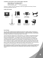
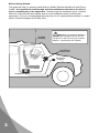
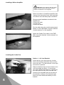
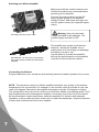
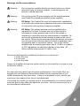
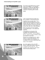
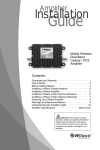
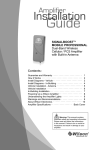
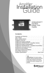
Amplifier Kit
Installation
stallat
stallatio
Guide
Mobile Wireless
Amplifier Kit with
Phone Cradle
Contents:
Guarantee and Warranty · · · · · · · · · · · · · · · · · · · · · · · · 1
How it Works · · · · · · · · · · · · · · · · · · · · · · · · · · · · · · · · · 2
Before Getting Started · · · · · · · · · · · · · · · · · · · · · · · · · · 3
Installing the Magnet-Mount Antenna · · · · · · · · · · · · · · · 4
Installing the Amplifier · · · · · · · · · · · · · · · · · · · · · · · · · · 5
Installing the Cradle Plus · · · · · · · · · · · · · · · · · · · · · · · · 5
Powering Up a Wilson Amplifier · · · · · · · · · · · · · · · · · · · 7
Connecting the Earbud · · · · · · · · · · · · · · · · · · · · · · · · · · 7
Warnings and Recommendations · · · · · · · · · · · · · · · · · 8
Understanding the Amplifier Lights · · · · · · · · · · · · · · · · 9
About Wilson Electronics · · · · · · · · · · · · · · · · · · · · · · · 10
Amplifier Specifications · · · · · · · · · · · · · · · · · · Back Cover
!
Warning: This manual contains
important safety and operating information.
Please read and follow the instructions
in this manual. Failure to do so could be
hazardous and result in damage to your
amplifier.
Wilson
®
Electronics, Inc.
30-Day Money-Back Guarantee
All Wilson Electronics products are protected by Wilson’s 30-day money-back
guarantee. If for any reason the performance of any product is not acceptable,
simply return the product directly to the reseller with a dated proof of purchase.
1-Year Warranty
Wilson Electronics amplifiers are warranted for one (1) year against defects in
workmanship and / or materials. Warranty cases may be resolved by returning the
product directly to the reseller with a dated proof of purchase.
Amplifiers may also be returned directly to the manufacturer at the consumer’s
expense, with a dated proof of purchase and a Returned Material Authorization
(RMA) number supplied by Wilson Electronics. Wilson shall, at its option, either
repair or replace the product. Wilson Electronics will pay for delivery of the repaired
or replaced product back to the original consumer.
This warranty does not apply to any amplifiers determined by Wilson Electronics
to have been subjected to misuse, abuse, neglect, or mishandling that alters or
damages physical or electronic properties.
RMA numbers may be obtained by phoning Technical Support at 866-294-1660.
Operation is subject to the following two conditions: (1) This device may not cause
interference, and (2) this device must accept any interference, including interference that
may cause undesired operation of this device.
Disclaimer: The information provided by Wilson Electronics, Inc. is believed to
be complete and accurate. However, no responsibility is assumed by Wilson
Electronics, Inc. for any business or personal losses arising from its use, or for
any infringements of patents or other rights of third parties that may result from
its use.
Copyright © 2007 Wilson Electronics, Inc. All rights reserved.
1
Installation Instructions for the Following Wilson Amplifier:
Mobile Wireless Dual-Band Amplifier
Model # 271245
Part # 801213
FCC ID: PWO8012SM
IC: 4726A-8012SM
The term “IC” before the radio certification number only signifies that Industry Canada
technical specifications were met.
Inside this Package
Wireless
amplifier
Cell Phone
Cradle Plus
Magnet-Mount
Antenna
Adhesive
Bracket
DC plug-in
power supply
Adhesive/Screw
Swivel Bracket
Earbud
Air-vent
Bracket
How it Works
Your new Wilson Mobile Wireless Amplifier Kit with Phone Cradle includes everything you
need to begin enjoying improved cellular performance in mobile applications. Using this kit
will amplify the signals to and from the cell phone that you place in its cradle, and will extend
the range of other phones or cellular data cards in the vehicle.
The kit includes the magnet-mount outside antenna, one of Wilson’s most popular products,
which will collect the signal from the cell tower and send it through the cable to the mobile
wireless dual-band amplifier. The amplifier’s state-of-the-art technology is designed to
increase your signal up to 10 times, reduce disconnects and dropouts, and increase data
communication rates needed for 3G technologies. The amplified signal is sent to the Cell
Phone Cradle Plus, Wilson’s versatile phone cradle, which has the inside antenna built right
in. Your cell phone or data card then communicates with the improved signal. When the cell
phone or data card transmits, the signal goes through the cradle antenna, is then boosted by
the amplifier and broadcast back to the cell tower through the outside antenna.
Most importantly, the Cradle Plus provides a convenient place to stow a phone and allows the
driver to keep both hands on the wheel while using the phone, greatly increasing safety. This
kit includes three mounting options for installing the cradle on the dash or console of your
vehicle.
2
Before Getting Started
This guide will help you properly install Wilson’s Mobile Wireless Amplifier Kit with Phone
Cradle. It is important to read through all of the installation instructions for this kit
prior to installing any of the equipment. Read through this installation guide, visualize
where all of the parts will be installed, and do a soft installation before mounting any
equipment. If you do not understand the instructions in full, seek professional help, or contact
Wilson Technical Support at 866-294-1660.
!
Outside
Antenna
Warning: In a wireless installation,
do not plug the amplifier directly into the
cell phone or data card using an antenna
adapter. It will damage the amplifier.
Cell Phone
Cradle Plus
DC Power
Supply
Amplifier
3
Installing the Magnet-Mount Antenna
To receive the best cell signal, select a location in the center of the vehicle’s roof that is 12
inches away from any other antennas and free of obstructions.
!
Warning: Do not use any type of glassmount antenna with this amplifier. The outside
antenna and Cradle Plus must be shielded
from each other to prevent oscillation.
The outside antenna must be installed
vertically. Signal performance will be
degraded if the antenna is not vertical.
Magnet-Mount
Antenna
The antenna cable may be run through the
door to the amplifier.
!
Warning: The outside antenna must
have a separation of at least 10 inches from all
persons during normal operation.
Carefully
Pull Down
Door Seal
Run Cable
Under
Seal
For a more professional-looking installation,
the antenna cable may be run under the
door seal. Carefully pull down the door
seal. Run the cable through the seal
and push the seal back into place. This
prevents constant wear and tear on the
cable as the door opens and closes.
The antenna cable is small enough to easily
tuck under the door seal or plastic molding.
Tuck Cable
Under Seal
4
Installing a Wilson Amplifier
!
Warning: Do not plug in the DC power
supply until the outside and inside antenna
cables are attached to the amplifier.
Select a location to install the amplifier that
is away from excessive heat, direct sunlight
or moisture and that has proper ventilation.
Recommended installation locations for the
amplifier are:
• Under the seat
• In the trunk
• Under the dash
Run the cable from the outside antenna and
attach it to the FME-Male connector labeled
“outside antenna” on the amplifier.
Attach the Cradle Plus cable to the FMEMale connector labeled “inside antenna” on
the amplifier.
Installing the Cradle Plus
Option 1 - Air Vent Bracket
Insert the two vent clips into the circular
hole in the bracket and slide them to each
end of the slot. The flat surface of the clips
should face upwards.
Slide the bracket clips into the chosen vent
until they snap into place. If necessary,
use a thin-bladed screwdriver to gently pry
the clips apart as they slide into the vent.
Position the moveable arm at the base of
the bracket to achieve the desired angle
and to provide additional stability for the
bracket.
5
Option 2 - Adhesive Bracket
Clean the area where the bracket is to be
mounted with rubbing alcohol and a soft
cloth. Allow to dry.
Peel the backing to expose the adhesive
and press the bracket onto the desired
location in the vehicle. Note: be sure
the bracket is positioned vertically, not
horizontally.
Allow the adhesive to cure for 24 hours
before you attach the cradle.
Note: Once the cradle is attached, you can
adjust the angle of the adhesive bracket
by applying gentle pressure to the top or
bottom of the cradle.
Option 3 - Adhesive/Screw Swivel
Bracket
Clean the area where the bracket is to be
mounted with rubbing alcohol and a soft
cloth. Allow to dry.
For an adhesive mount, peel the backing
to expose the adhesive and press the
bracket onto the desired location in the
vehicle. Allow the adhesive to cure for 24
hours before you attach the cradle.
For best mounting results and longterm performance, we suggest that
you choose a flat smooth surface
like the console area of your vehicle
between the two front seats. If this is
not available in your vehicle, you may
mount the cradle on the front of the
dashboard.
If mounting the cradle on a sloped
area of the dashboard in your vehicle,
please note that gravity may affect
the adhesive over time. Use the
screw mount for a more permanent
attachment.
For a screw mount, use an ice pick or awl
to punch through the adhesive and expose
the four screw holes in the bracket. You
must provide the screws of an appropriate
size for your particular application. Using
the bracket as a template, mark the
locations for the screws as shown, drill pilot
holes and attach the bracket with screws.
Once the cradle is attached, you can
loosen the knurled wheel and swivel the
hook to the desired angle, then re-tighten
the wheel.
Attaching the Cradle
Once you have installed the mount in the desired location, attach the cradle by aligning
the rectangular hole on its back with the hook on the mount. Grasping the sides of the
cradle, slide it downward approximately ¼ inch into place.
6
Powering up a Wilson Amplifier
Make sure both the outside antenna and
Cradle Plus cables are connected before
powering up the amplifier.
Connect the power cable from the DC
plug-in power supply to the amplifier
marked “Power” and insert the large end
into DC power socket (the cigarette lighter
outlet.)
Carefully insert the power cable.
!
Warning: Use only the power
supply provided in this package. The
power supply must be 6 V DC.
The amplifier may remain on all the time.
However, leaving the amplifier on in a
vehicle when it is not running can discharge
the battery in a day or two.
IMPORTANT: Do not power up the amplifier unless antenna cables are attached to
amplifier.
A good option is to power the amplifier
through the ignition switch so the amplifier
is turned on and off with the vehicle.
Connecting the Earbud
Plug the earbud into your cell phone and carefully place the earbud’s speaker into your ear.
NOTE: The aluminum casing of a Wilson amplifier will adjust very quickly to the ambient
temperature of its environment. For example, in the summer, when the inside of a car can
reach 140 degrees Fahrenheit, the amplifier temperature may be 150 degrees or higher.
The casing will be hot to the touch, similar to a metal door handle or a steering wheel. Such
high temperatures will not damage the amplifier, nor do they pose a fire risk to the vehicle.
As recommended in these instructions, install the amplifier in a location with adequate
ventilation, such as under the seat, in the trunk or under the dashboard. Keep the area free
of items that could block air flow to the amplifier.
7
Warnings and Recommendations
Warning:
Do not plug the amplifier directly into the cell phone or cellular
data card using an antenna adapter. It will damage the cell
phone or cellular data card.
Warning:
Do not plug in the DC power supply until the outside antenna
and Cradle Plus cables are attached to the amplifier.
Warning:
RF Safety: The Cradle Plus must be installed with a separation
of at least eight inches from all persons and must not be located
in conjunction with any other antenna or amplifier.
Warning:
RF Safety: The outside antenna must be installed with a
separation of at least 10 inches from any of the vehicle’s
occupants or nearby persons and must not be located or
operating in conjunction with any other antenna or amplifier. All
roof-mount antennas should be centrally located on the roof of
the vehicle. Mirror-mount antennas should be at least six inches
from the ground and leave at least 20 inches of separation from
any persons near or around the vehicle. Use of this cellular
amplifier with an antenna gain higher than 6.12 dBi is in violation
of FCC regulations for which the offender is fully liable. All
Wilson mobile antennas are 6.12 dBi or less.
Recommended amplifier installation locations for a vehicle are:
• Under the seat
• In the trunk
• Under the dash
Power the amplifier through the ignition switch so the amplifier is turned on and
off with the vehicle.
For best mounting results and long-term performance of the Cradle Plus, we
suggest that you choose a flat smooth surface like the console area of your
vehicle between the two front seats. If this is not available in your vehicle, you
may mount the cradle on the front of the dashboard.
If mounting the cradle on a sloped area of the dashboard in your vehicle, please
note that gravity may affect the adhesive over time. Use the screw mount for a
more permanent attachment.
8
Understanding the Amplifier Lights
The power light PWR will turn green
when the amplifier is successfully
powered up. When the 800 MHz or
1900 MHz lights are lit green, the
amplifier is amplifying the outside
signal.
If one or both frequency lights turn
red, oscillation is occurring and the
amplifier has powered down. The
outside antenna needs to be moved
farther from the Cradle Plus. Move the
outside antenna on the roof of the car
to the rear of the car, but at least 8-12
inches from the rear or side windows.
Remove power from the amplifier
and reinstall power - this resets the
amplifier.
If the lights are now green, the
oscillation has stopped and the
amplifier is working. If the red light is
still on, move the antenna farther away
and repeat the process.
Always use a magnet-mount, mirrormount or roof-mount antenna. Do
not use a glass-mount antenna, as
oscillation may cause continuous shutdown of the amplifier.
An amber light in either the 800
MHz or 1900 MHz position indicates
overload from the cell site. The
amplifier has temporarily shut down
and will automatically reset.
9
About Wilson Electronics
Wilson Electronics, Inc. has been a leader in the wireless communications
industry for nearly 40 years. The company designs and manufactures amplifiers,
antennas and related components that significantly improve cellular telephone
signal reception and transmission in a wide variety of applications, both mobile
and in-building.
With extensive experience in antenna and amplifier research and design, the
company’s engineering team uses a state-of-the-art testing laboratory, including
an anechoic chamber and network analyzers, to fine-tune antenna designs and
performance. For its amplifiers, Wilson uses a double electrically insulated RF
enclosure and cell site simulators for compliance testing.
All products are engineered and assembled in the company’s 50,000-square-foot
headquarters in St. George, Utah. Wilson has product dealers in all 50 states as
well as Canada and Mexico, Central and South America.
10
Amplifier Specifications
Dual Band
800/1900 MHz Specifications
271245 / 801201
FME-Male
50 ohms
5.6 x 3.6 x 1.7 inch or 14.2 x 9.1 x 4.4 cm
1.44 lbs or 0.65 kg
824-894 MHz / 1850-1990 MHz
Model Number / Part Number
Connectors
Impedance (input/output)
Dimensions
Weight
Frequency
1
Passband Gain (nominal)
800 MHz
1900 MHz
2
40 dB (typical) / 45 dB (maximum)
45 dB (typical) / 50 dB (maximum)
20 dB Bandwidth (nominal)
800 MHz (uplink/downlink)
1900 MHz (uplink/downlink)
Power output for single cell phone (uplink)
CDMA
GSM
EDGE
AMPS
3
Power output (uplink) for multiple
cell phones:
Number of
cell phones
2
3
4
5
6
Power output for single received channel
(downlink)
CDMA
GSM
EDGE
AMPS
53.5 MHz / 47.7 MHz
86 MHz / 83 MHz
800 MHz
+30.9 dBm
+30.0 dBm
+30.4 dBm
+30.2 dBm
1900 MHz
+30.5 dBm
+29.7 dBm
+30.3 dBm
Maximum Power
800 MHz
1900 MHz
+25.0 dBm
+21.5 dBm
+19.0 dBm
+17.0 dBm
+15.5 dBm
+24.7 dBm
+21.2 dBm
+18.7 dBm
+16.7 dBm
+15.2 dBm
800 MHz
1900 MHz
+10.0 dBm
+11.0 dBm
+10.9 dBm
+10.3 dBm
+9.9 dBm
+9.9 dBm
+9.6 dBm
4
Power output for multiple received
channels (downlink). The maximum
power is reduced by the number of
channels:
Noise Figure (typical)
Isolation
Power Requirements
Amplifier Usage
Maximum Power
Number of
channels
2
3
4
5
6
800 MHz
1900 MHz
-11.6 dBm
-15.1 dBm
-17.6 dBm
-19.6 dBm
-21.1 dBm
-3.1 dBm
-6.6 dBm
-9.1 dBm
-11.1 dBm
-12.6 dBm
3 dB nominal
> 90 dB
6 V, .5 A - 1.5 A (subject to uplink power)
Notes:
1. Nominal gain is the maximum gain at any frequency in the passband.
Average gains are: 37 dB (800 MHz uplink & downlink) 45 dB (1900 MHz uplink & downlink)
2. Nominal bandwidth is the difference between two frequencies that are adjacent to the passband where the amplification is 20 dB
lower than the passband amplification. One of the frequencies is lower than the passband and the other is higher.
3. The Manufacturer’s rated output power of this equipment is for single carrier operation. For situations when multiple carrier
signals are present, the rating would have to be reduced by 3.5 dB, especially where the output signal is re-radiated and can
cause interference to adjacent band users. This power reduction is to be by means of input power or gain reduction and not by
an attenuator at the output of the device.
4. The maximum power for 2 or more simultaneous signals will be reduced by 6 dB every time the number of signals is doubled.
Phone: 866-294-1660
Wilson® Electronics, Inc.
www.wilsonelectronics.com Fax: 435-656-2432
Part #110463 AIG MWCK 004 / 11.30.07