1
Dominion KX II
User Guide
Release 2.6.0
Copyright © 2014 Raritan, Inc.
DKX2-v2.6.0-0R-E
March 2014
255-62-4023-00
This document contains proprietary information that is protected by copyright. All rights reserved. No
part of this document may be photocopied, reproduced, or translated into another language without
express prior written consent of Raritan, Inc.
© Copyright 2014 Raritan, Inc. All third-party software and hardware mentioned in this document are
registered trademarks or trademarks of and are the property of their respective holders.
FCC Information
This equipment has been tested and found to comply with the limits for a Class A digital device,
pursuant to Part 15 of the FCC Rules. These limits are designed to provide reasonable protection
against harmful interference in a commercial installation. This equipment generates, uses, and can
radiate radio frequency energy and if not installed and used in accordance with the instructions, may
cause harmful interference to radio communications. Operation of this equipment in a residential
environment may cause harmful interference.
VCCI Information (Japan)
Raritan is not responsible for damage to this product resulting from accident, disaster, misuse, abuse,
non-Raritan modification of the product, or other events outside of Raritan's reasonable control or not
arising under normal operating conditions.
If a power cable is included with this product, it must be used exclusively for this product.
In Raritan products that require Rack Mounting, please follow these precautions:
Operation temperature in a closed rack environment may be greater than room temperature. Do
not exceed the rated maximum ambient temperature of the appliances. See Specifications (on
page 287) in online help.
Ensure sufficient airflow through the rack environment.
Mount equipment in the rack carefully to avoid uneven mechanical loading.
Connect equipment to the supply circuit carefully to avoid overloading circuits.
Ground all equipment properly, especially supply connections, such as power strips (other than
direct connections), to the branch circuit.
Contents
Chapter 1
Introduction
1
KX II Overview ............................................................................................................................... 2
Package Contents .......................................................................................................................... 4
KX II Device Photos and Features ................................................................................................. 5
Product Features ........................................................................................................................... 7
Hardware ............................................................................................................................. 7
Software ............................................................................................................................... 8
KX II Client Applications................................................................................................................. 9
KX II Help ....................................................................................................................................... 9
Chapter 2
Installation and Configuration
10
Overview ...................................................................................................................................... 10
Rack Mounting ............................................................................................................................. 10
Forward Mount................................................................................................................... 10
Rear Mount ........................................................................................................................ 11
Default Login Information ............................................................................................................. 12
Getting Started ............................................................................................................................. 12
Step 1: Configuring Network Firewall Settings .................................................................. 12
Step 2: Configure the KVM Target Servers ....................................................................... 13
Step 3: Connect the Equipment......................................................................................... 16
Step 4: Configure the KX II ................................................................................................ 18
Step 5: Launching the KX II Remote Console ................................................................... 23
Step 6: Configuring the Keyboard Language (Optional) ................................................... 24
Step 7: Configure Tiering (Optional) .................................................................................. 25
Logging in to the KX II.................................................................................................................. 25
Allow Pop-Ups ............................................................................................................................. 26
Security Warnings and Validation Messages .............................................................................. 26
Java Validation and Access Warning ................................................................................ 26
Additional Security Warnings ............................................................................................. 27
Installing a Certificate................................................................................................................... 27
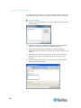
Example 1: Import the Certificate into the Browser ........................................................... 28
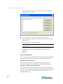
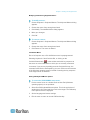
Example 2: Add the KX II to Trusted Sites and Import the Certificate .............................. 30
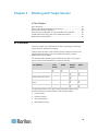
Chapter 3
Working with Target Servers
32
KX II Interfaces ............................................................................................................................ 32
KX II Local Console Interface: KX II Devices .............................................................................. 33
KX II Remote Console Interface .................................................................................................. 33
KX II Interface .................................................................................................................... 34
Left Panel ........................................................................................................................... 35
KX II Console Navigation ................................................................................................... 37
iii
Contents
Port Access Page (Remote Console Display) ................................................................... 38
Port Action Menu ............................................................................................................... 41
Managing Favorites ........................................................................................................... 43
Scanning Ports .................................................................................................................. 47
Logging Out ....................................................................................................................... 50
Proxy Server Configuration for Use with MPC, VKC and AKC.................................................... 50
Virtual KVM Client (VKC) and Active KVM Client (AKC) ............................................................. 52
Overview ............................................................................................................................ 52
Virtual KVM Client Java Requirements ............................................................................. 52
Virtual KVM Client (VKC) and Active KVM Client (AKC) Shared Features ....................... 53
Connect to a Target Server ............................................................................................... 53
Connection Properties ....................................................................................................... 54
Connection Information ..................................................................................................... 56
Connection Properties ....................................................................................................... 57
Toolbar Buttons and Status Bar Icons ............................................................................... 58
Keyboard Options .............................................................................................................. 60
Video Properties ................................................................................................................ 66
Mouse Options................................................................................................................... 70
Tool Options ...................................................................................................................... 75
View Options ...................................................................................................................... 79
Digital Audio....................................................................................................................... 82
Smart Cards....................................................................................................................... 89
Version Information - Virtual KVM Client ........................................................................... 91
About the Active KVM Client ............................................................................................. 92
Multi-Platform Client (MPC) ......................................................................................................... 94
Launching MPC from a Web Browser ............................................................................... 94
Launching MPC on Mac Lion Clients ................................................................................ 95
Chapter 4
Virtual Media
96
Prerequisites for Using Virtual Media .......................................................................................... 96
KX II Virtual Media Prerequisites ....................................................................................... 96
Remote PC VM Prerequisites ............................................................................................ 97
Target Server VM Prerequisites ........................................................................................ 97
CIMs Required for Virtual Media ....................................................................................... 97
Mounting Local Drives ................................................................................................................. 97
Notes on Mounting Local Drives ........................................................................................ 97
Supported Tasks Via Virtual Media ............................................................................................. 98
Supported Virtual Media Types ................................................................................................... 98
Conditions when Read/Write is Not Available ................................................................... 98
Supported Virtual Media Operating Systems .............................................................................. 99
Number of Supported Virtual Media Drives ................................................................................. 99
Connecting and Disconnecting from Virtual Media .................................................................... 100
Access a Virtual Media Drive on a Client Computer ....................................................... 100
Mounting CD-ROM/DVD-ROM/ISO Images .................................................................... 101
Disconnect from Virtual Media Drives ............................................................................. 102
Virtual Media in a Windows XP Environment ............................................................................ 102
Virtual Media in a Linux Environment ........................................................................................ 102
Active System Partitions .................................................................................................. 102
Drive Partitions ................................................................................................................ 103
Root User Permission Requirement ................................................................................ 103
iv
Contents
Virtual Media in a Mac Environment .......................................................................................... 103
Active System Partition .................................................................................................... 103
Drive Partitions ................................................................................................................ 103
Virtual Media File Server Setup (File Server ISO Images Only)................................................ 104
Chapter 5
Rack PDU (Power Strip) Outlet Control
105
Overview .................................................................................................................................... 105
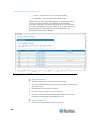
Turning Outlets On/Off and Cycling Power ............................................................................... 106
Chapter 6
USB Profiles
108
Overview .................................................................................................................................... 108
CIM Compatibility ....................................................................................................................... 109
Available USB Profiles ............................................................................................................... 109
Mouse Modes when Using the Mac Boot Menu .............................................................. 115
Selecting Profiles for a KVM Port .............................................................................................. 115
Chapter 7
User Management
116
User Groups ............................................................................................................................... 116
User Group List................................................................................................................ 117
Relationship Between Users and Groups ....................................................................... 117
Adding a New User Group ............................................................................................... 117
Modifying an Existing User Group ................................................................................... 124
Users .......................................................................................................................................... 125
Adding a New User .......................................................................................................... 125
View the KX II Users List ................................................................................................. 126
View Users by Port .......................................................................................................... 126
Disconnecting Users from Ports ...................................................................................... 127
Logging Users Off the KX II (Force Logoff) ..................................................................... 127
Modifying an Existing User .............................................................................................. 128
Authentication Settings .............................................................................................................. 128
Implementing LDAP/LDAPS Remote Authentication ...................................................... 129
Returning User Group Information from Active Directory Server .................................... 133
Implementing RADIUS Remote Authentication ............................................................... 134
Returning User Group Information via RADIUS .............................................................. 137
RADIUS Communication Exchange Specifications ......................................................... 137
User Authentication Process ........................................................................................... 139
Changing a Password ................................................................................................................ 140
Chapter 8
Device Management
141
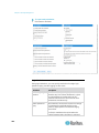
Network Settings ........................................................................................................................ 141
Network Basic Settings .................................................................................................... 141
Assign the KX II an IP Address ....................................................................................... 142
Configure the IPv4 Settings ............................................................................................. 142
Configure the IPv6 Settings ............................................................................................. 143
Configure the DNS Settings ............................................................................................ 143
v
Contents
LAN Interface Settings ..................................................................................................... 144
Device Services ......................................................................................................................... 145
Enabling SSH .................................................................................................................. 145
HTTP and HTTPS Port Settings ...................................................................................... 146
Entering the Discovery Port ............................................................................................. 146
Configuring and Enabling Tiering .................................................................................... 147
Enabling Direct Port Access via URL .............................................................................. 152
Enabling the AKC Download Server Certificate Validation ............................................. 156
Configuring SNMP Agents ............................................................................................... 157
Configuring Modem Settings ........................................................................................... 159
Configuring Date/Time Settings ....................................................................................... 161
Event Management ......................................................................................................... 162
Power Supply Setup .................................................................................................................. 170
Configuring Ports ....................................................................................................................... 171
Configuring Standard Target Servers .............................................................................. 173
Configuring KVM Switches .............................................................................................. 174
Configuring CIM Ports ..................................................................................................... 176
Configuring Rack PDU (Power Strip) Targets ................................................................. 177
Configuring Blade Chassis .............................................................................................. 183
Configuring USB Profiles (Port Page) ............................................................................. 204
Configuring KX II Local Port Settings .............................................................................. 206
Connect and Disconnect Scripts ................................................................................................ 211
Applying and Removing Scripts ....................................................................................... 211
Adding Scripts.................................................................................................................. 212
Modifying Scripts ............................................................................................................. 215
Importing and Exporting Scripts ...................................................................................... 215
Port Group Management ........................................................................................................... 216
Creating Port Groups ....................................................................................................... 217
Creating a Dual Video Port Group ................................................................................... 218
Changing the Default GUI Language Setting ............................................................................ 219
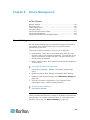
Chapter 9
Security Management
221
Security Settings ........................................................................................................................ 221
Login Limitations .............................................................................................................. 222
Strong Passwords............................................................................................................ 224
User Blocking................................................................................................................... 225
Encryption & Share .......................................................................................................... 227
Enabling FIPS 140-2 ....................................................................................................... 230
Configuring IP Access Control ................................................................................................... 232
SSL Certificates ......................................................................................................................... 234
Security Banner ......................................................................................................................... 237
Chapter 10
Maintenance
239
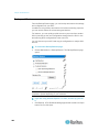
Audit Log .................................................................................................................................... 239
Device Information ..................................................................................................................... 240
Backup and Restore .................................................................................................................. 242
USB Profile Management .......................................................................................................... 244
Handling Conflicts in Profile Names ................................................................................ 245
vi
Contents
Upgrading CIMs ......................................................................................................................... 245
Upgrading Firmware .................................................................................................................. 245
Upgrade History ......................................................................................................................... 247
Rebooting the KX II .................................................................................................................... 248
Stopping CC-SG Management .................................................................................................. 249
Chapter 11
Diagnostics
251
Network Interface Page ............................................................................................................. 251
Network Statistics Page ............................................................................................................. 251
Ping Host Page .......................................................................................................................... 253
Trace Route to Host Page ......................................................................................................... 254
Device Diagnostics .................................................................................................................... 255
Chapter 12
Command Line Interface (CLI)
257
Overview .................................................................................................................................... 257
Accessing the KX II Using CLI ................................................................................................... 258
SSH Connection to the KX II ..................................................................................................... 258
SSH Access from a Windows PC .................................................................................... 258
SSH Access from a UNIX/Linux Workstation .................................................................. 258
Logging In .................................................................................................................................. 259
Navigation of the CLI ................................................................................................................. 259
Completion of Commands ............................................................................................... 259
CLI Syntax -Tips and Shortcuts ....................................................................................... 260
Common Commands for All Command Line Interface Levels ........................................ 260
Initial Configuration Using CLI ................................................................................................... 261
Setting Parameters .......................................................................................................... 261
Setting Network Parameters ............................................................................................ 261
CLI Prompts ............................................................................................................................... 262
CLI Commands .......................................................................................................................... 262
Security Issues ................................................................................................................ 263
Administering the KX II Console Server Configuration Commands .......................................... 263
Configuring Network .................................................................................................................. 263
Interface Command ......................................................................................................... 264
Name Command ........................................................................................................... 265
IPv6 Command ................................................................................................................ 265
Chapter 13
KX II Local Console
266
Overview .................................................................................................................................... 266
Simultaneous Users ................................................................................................................... 266
KX II Local Console Interface: KX II Devices ............................................................................ 267
Security and Authentication ....................................................................................................... 267
Available Resolutions................................................................................................................. 267
Port Access Page (Local Console Server Display) ................................................................... 268
Accessing a Target Server ........................................................................................................ 268
Scanning Ports - Local Console ................................................................................................ 269
Local Port Scan Mode ..................................................................................................... 270
vii
Contents
Local Console Smart Card Access ............................................................................................ 270
Smart Card Access in KX2 8xx Devices ......................................................................... 271
Local Console USB Profile Options ........................................................................................... 272
Hot Keys and Connect Keys ...................................................................................................... 273
Connect Key Examples ................................................................................................... 273
Special Sun Key Combinations ................................................................................................. 274
Returning to the KX II Local Console Interface ......................................................................... 275
Local Port Administration ........................................................................................................... 275
Configuring KX II Local Console Local Port Settings ...................................................... 275
KX II Local Console Factory Reset.................................................................................. 279
Connect and Disconnect Scripts ................................................................................................ 281
Applying and Removing Scripts ....................................................................................... 281
Adding Scripts.................................................................................................................. 282
Modifying Scripts ............................................................................................................. 285
Resetting the KX II Using the Reset Button ............................................................................... 285
Appendix A Specifications
287
Hardware ................................................................................................................................... 287
KX II Physical Specifications ........................................................................................... 287
Supported Target Server Video Resolution/Refresh Rate/Connection Distance ............ 289
Supported Computer Interface Module (CIMs) Specifications ........................................ 289
Digital CIM Target Server Timing and Video Resolution ................................................. 292
Digital Video CIMs for Macs ............................................................................................ 295
Supported Paragon II CIMS and Configurations ............................................................. 296
Supported Remote Connections ..................................................................................... 300
Network Speed Settings .................................................................................................. 300
Dell Chassis Cable Lengths and Video Resolutions ....................................................... 301
Smart Card Minimum System Requirements .................................................................. 301
Supported and Unsupported Smart Card Readers ......................................................... 303
Supported Audio Device Formats.................................................................................... 305
Audio Playback and Capture Recommendations and Requirements ............................. 305
Number of Supported Audio/Virtual Media and Smartcard Connections ........................ 307
Certified Modems............................................................................................................. 307
Devices Supported by the Extended Local Port .............................................................. 307
KX2 8xx Extended Local Port Recommended Maximum Distances ............................... 308
Mac Mini BIOS Keystroke Commands ............................................................................ 308
Using a Windows Keyboard to Access Mac Targets ....................................................... 309
TCP and UDP Ports Used ............................................................................................... 309
Software ..................................................................................................................................... 311
Supported Operating Systems (Clients) .......................................................................... 311
Supported Browsers ........................................................................................................ 312
Supported Video Resolutions .......................................................................................... 313
KX II Supported Keyboard Languages ............................................................................ 315
Events Captured in the Audit Log and Syslog ................................................................. 316
viii
Contents
Appendix B Dual Video Port Groups
317
Overview .................................................................................................................................... 317
Recommendations for Dual Port Video ..................................................................................... 318
Dual Video Port Group Supported Mouse Modes ..................................................................... 318
CIMs Required for Dual Video Support ..................................................................................... 319
Dual Port Video Group Usability Notes...................................................................................... 319
Permissions and Dual Video Port Group Access ...................................................................... 320
Example Dual Port Video Group Configuration ......................................................................... 321
Dual Port Video Configuration Steps ......................................................................................... 322
Step 1: Configure the Target Server Display ................................................................... 322
Step 2: Connect the Target Server to the KX III .............................................................. 323
Step 3: Configure the Mouse Mode and Ports ................................................................ 324
Step 4: Create the Dual Video Port Group ...................................................................... 324
Step 5: Launch a Dual Port Video Group ........................................................................ 325
Raritan Client Navigation when Using Dual Video Port Groups ................................................ 325
Direct Port Access and Dual Port Video Groups ....................................................................... 326
Dual Port Video Groups Displayed on the Ports Page .............................................................. 326
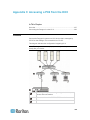
Appendix C
Accessing a PX2 from the KX II
327
Overview .................................................................................................................................... 327
Connecting the Paragon II to the KX II ...................................................................................... 328
Appendix D Updating the LDAP Schema
330
Returning User Group Information ............................................................................................. 330
From LDAP/LDAPS ......................................................................................................... 330
From Microsoft Active Directory ...................................................................................... 330
Setting the Registry to Permit Write Operations to the Schema ............................................... 331
Creating a New Attribute ............................................................................................................ 331
Adding Attributes to the Class ................................................................................................... 332
Updating the Schema Cache ..................................................................................................... 334
Editing rciusergroup Attributes for User Members ..................................................................... 334
Appendix E
Informational Notes
337
Overview .................................................................................................................................... 337
Java Runtime Environment (JRE) Notes ................................................................................... 337
Java Runtime Environment (JRE) ................................................................................... 337
Java Not Loading Properly on Mac ................................................................................. 338
IPv6 Support Notes .................................................................................................................... 339
Operating System IPv6 Support Notes ........................................................................... 339
AKC Download Server Certification Validation IPv6 Support Notes ............................... 339
Dual Stack Login Performance Issues ....................................................................................... 340
CIM Notes .................................................................................................................................. 340
Windows 3-Button Mouse on Linux Targets .................................................................... 340
Windows 2000 Composite USB Device Behavior for Virtual Media ................................ 341
ix
Contents
Virtual Media Notes .................................................................................................................... 341
Cannot Connect to Drives from Linux Clients ................................................................. 341
Cannot Write To/From a File from a Mac Client .............................................................. 342
Virtual Media via VKC and AKC in a Windows Environment .......................................... 343
Virtual Media Not Refreshed After Files Added ............................................................... 343
Virtual Media Linux Drive Listed Twice............................................................................ 344
Accessing Virtual Media on a Windows 2000 ................................................................. 344
Disconnecting Mac and Linux Virtual Media USB Drives ................................................ 344
Target BIOS Boot Time with Virtual Media ...................................................................... 344
Virtual Media Connection Failures Using High Speed for Virtual Media Connections .... 344
USB Port and Profile Notes ....................................................................................................... 345
VM-CIMs and DL360 USB Ports ..................................................................................... 345
Help Choosing USB Profiles ............................................................................................ 345
Changing a USB Profile when Using a Smart Card Reader ........................................... 347
Keyboard Notes ......................................................................................................................... 347
Non-US Keyboards .......................................................................................................... 347
Mac Keyboard Keys Not Supported for Remote Access................................................. 350
Video Mode and Resolution Notes ............................................................................................ 350
SUSE/VESA Video Modes .............................................................................................. 350
List of Supported Target Video Resolutions Not Displaying ........................................... 351
Audio .......................................................................................................................................... 351
Audio Playback and Capture Issues................................................................................ 351
Audio in a Linux Environment .......................................................................................... 352
Audio in a Windows Environment .................................................................................... 352
CC-SG Notes ............................................................................................................................. 352
Virtual KVM Client Version Not Known from CC-SG Proxy Mode .................................. 352
Single Mouse Mode when Connecting to a Target Under CC-SG Control ..................... 352
Proxy Mode and MPC ..................................................................................................... 353
Moving Between Ports on a Device................................................................................. 353
Browser Notes ........................................................................................................................... 353
Resolving Fedora Core Focus ......................................................................................... 353
Mouse Pointer Synchronization (Fedora) ........................................................................ 353
VKC and MPC Smart Card Connections to Fedora Servers ........................................... 354
Resolving Issues with Firefox Freezing when Using Fedora .......................................... 354
x
Contents
Appendix F Frequently Asked Questions
355
General FAQs ............................................................................................................................ 355
Remote Access .......................................................................................................................... 356
Universal Virtual Media .............................................................................................................. 359
Bandwidth and KVM-over-IP Performance ................................................................................ 361
Ethernet and IP Networking ....................................................................................................... 367
IPv6 Networking ......................................................................................................................... 369
Servers ....................................................................................................................................... 371
Blade Servers ............................................................................................................................ 372
Installation .................................................................................................................................. 374
Local Port ................................................................................................................................... 376
Extended Local Port (Dominion KX2-832 and KX2-864 models only) ...................................... 378
Intelligent Power Distribution Unit (PDU) Control ...................................................................... 379
Local Port Consolidation, Tiering and Cascading ...................................................................... 380
Computer Interface Modules (CIMs) .......................................................................................... 383
Security ...................................................................................................................................... 384
Smart Cards and CAC Authentication ....................................................................................... 386
Manageability ............................................................................................................................. 386
Documentation and Support ...................................................................................................... 388
Miscellaneous ............................................................................................................................ 388
Index
391
xi
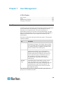
Chapter 1
Introduction
In This Chapter
KX II Overview ...........................................................................................2
Package Contents .....................................................................................4
KX II Device Photos and Features ............................................................5
Product Features .......................................................................................7
KX II Client Applications ............................................................................9
KX II Help...................................................................................................9
1
Chapter 1: Introduction
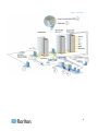
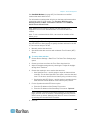
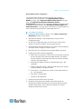
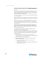
KX II Overview
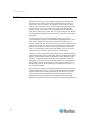
Raritan's Dominion KX II is an enterprise-class, secure, digital KVM
(Keyboard, Video, Mouse) switch that provides BIOS-level (and up)
access and control of servers from anywhere in the world via a web
browser. Up to 64 servers can be controlled with a standard KX II. With
the KX II 8-user model, up to 32 servers can be controlled with the
KX2-832 and up to 64 servers can be controlled with the KX2-864. A
scan feature allows you to locate and view up to 32 targets. The targets
are displayed as thumbnails in a slide show from which users connect to
each target.
The KX II supports up to 8 video channels, allowing up to eight
concurrent users to connect to eight different video targets at any given
point in time. Digital audio devices are supported, allowing you to
connect to playback and record devices from the remote client PC to the
target server. At the rack, the KX II provides BIOS-level control of up to
64 servers and other IT devices from a single keyboard, monitor, and
mouse. The integrated remote access capabilities of the KX II provide
the same levels of control of your servers via a web browser.
The KX II is easily installed using standard UTP (Cat 5/5e/6) cabling. Its
advanced features include virtual media, 256-bit encryption, dual power
supplies, remote power control, dual Ethernet, LDAP, RADIUS, Active
Directory®, Syslog integration, external modem capabilities, and web
management. The KX II 8-user model also provides an extended local
port located on the back of the device. These features enable you to
deliver higher up-time, better productivity, and bulletproof security - at
any time from anywhere.
KX II products can operate as standalone appliances and do not rely on
a central management device. For larger data centers and enterprises,
numerous KX II devices (along with Dominion SX devices for remote
serial console access and Dominion KSX for remote/branch office
management) can be integrated into a single logical solution using
Raritan's CommandCenter Secure Gateway (CC-SG) management unit.
2
Chapter 1: Introduction
3
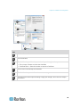
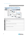
Chapter 1: Introduction
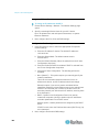
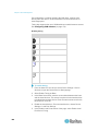
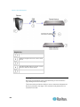
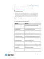
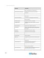
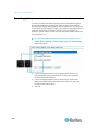
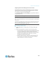
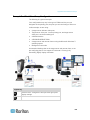
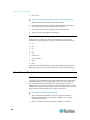
Diagram key
Local port access
Tiering
IP-based network
access
Extended local port
Modem
Mobile access via iPhone®
and iPad® using CC-SG
Virtual media
Digital audio
Smart card access at
the rack
CIMs
Remote smart card
access
Cat5/6 cable
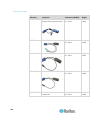
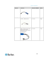
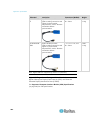
Package Contents
Each KX II ships as a fully-configured stand-alone product in a standard
1U (2U for DKX2-864) 19" rackmount chassis. Each KX II device ships
with the following contents:
4
1 - KX II device
1 - KX II Quick Setup Guide
1 - Rackmount kit
2 - AC power cords
2 - Cat5 network cable
1 - Cat5 network crossover cable
1 - Set of 4 rubber feet (for desktop use)
1 - Application note
1 - Warranty card
Chapter 1: Introduction
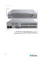
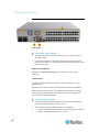
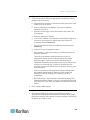
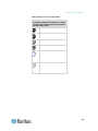
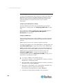
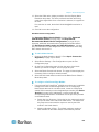
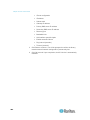
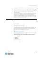
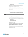
KX II Device Photos and Features
KX II
KX2-808
5
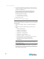
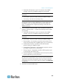
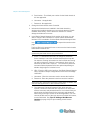
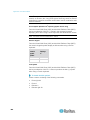
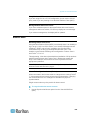
Chapter 1: Introduction
KX2-832
KX2-864
See KX II Dimensions and Physical Specifications (on page 287) for
product specifications. See Supported Computer Interface Module
(CIMs) Specifications (on page 289) for CIM specifications and images.
6
Chapter 1: Introduction
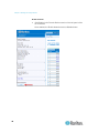
Product Features
Hardware
Integrated KVM-over-IP remote access
1U or 2U rack-mountable (brackets included)
Dual power supplies with failover; autoswitching power supply with
power failure warning
Support for tiering in which a base KX II device is used to access
multiple other tiered devices. See Configuring and Enabling
Tiering (on page 147) for more information on tiering.
Multiple user capacity (1/2/4/8 remote users; 1 local user)
UTP (Cat5/5e/6) server cabling
Dual Ethernet ports (10/100/1000 LAN) with failover
Field upgradable
Local User port for in-rack access
Keyboard/mouse ports on the KX2-808, KX2-832 and KX2-864
are USB only
One front and three back panel USB 2.0 ports for supported USB
devices
Fully concurrent with remote user access
Local graphical user interface (GUI) for administration
Extended local port provides extended reach to in-rack access on
KX2-8xx devices
Centralized access security
Integrated power control
LED indicators for dual power status, network activity, and remote
user status
Hardware Reset button
Serial port to connect to an external modem
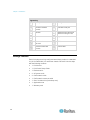
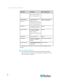
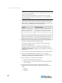
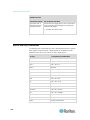
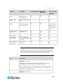
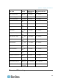
Supported users and ports per model:
Model
Remote users
Ports
KX II-864
8
64
KX II-832
8
32
KX II-808
8
8
KX II-464
4
64
KX II-432
4
32
7
Chapter 1: Introduction
Model
Remote users
Ports
KX II-416
4
16
KX II-232
2
32
KX II-216
2
16
KX II-132
1
32
KX II-116
1
16
KX II-108
1
8
Software
8
Virtual media support in Windows®, Mac® and Linux® environments
with D2CIM-VUSB and D2CIM-DVUSB CIMs and digital CIMs
Support for digital audio over USB
Port scanning and thumbnail view of up to 32 targets within a
configurable scan set
Absolute Mouse Synchronization with D2CIM-VUSB CIM,
D2CIM-DVUSB CIM and digital CIMs
Plug-and-Play
Web-based access and management
Intuitive graphical user interface (GUI)
Support for dual port video output
256-bit encryption of complete KVM signal, including video and
virtual media
LDAP, Active Directory®, RADIUS, or internal authentication and
authorization
DHCP or fixed IP addressing
Smart card/CAC authentication
SNMP, SNMP3 and Syslog management
IPv4 and IPv6 support
Power control associated directly with servers to prevent mistakes
Integration with Raritan's CommandCenter Secure Gateway (CC-SG)
management unit
CC Unmanage feature to remove device from CC-SG control
Support of Raritan PX1 and PX2 appliances
Chapter 1: Introduction
KX II Client Applications
The following client applications can be used in the KX II:
KX II 2.2 (and later):
Virtual KVM Client (VKC)
Active KVM Client (AKC)
Multi-Platform Client (MPC)
KX II (Generation 2):
Virtual KVM Client (VKC)
Multi-Platform Client (MPC)
Java™ 1.7 is required to use the Java-based Java-based KX II Virtual
KVM Client (VKC) and Multi-Platform Client (MPC)..
Microsoft .NET® 3.5 (or later) is required to use KX II with the Microsoft
Windows®-based Active KVM Client (AKC).
KX II Help
KX II online help is considered your primary help resource. PDF versions
of help are a secondary resource.
See the KX II Release Notes for important information on the current
release before you begin using the KX II.
KVM Client help is provided as part of KX II online help.
Online help is accompanied by the KX II Quick Setup Guide, which is
included with your KX II and can be found on the Raritan Support page
of Raritan's website
(http://www.raritan.com/support/firmware-and-documentation).
Note: To use online help, Active Content must be enabled in your
browser.
9
Chapter 2
Installation and Configuration
In This Chapter
Overview ..................................................................................................10
Rack Mounting .........................................................................................10
Default Login Information ........................................................................12
Getting Started ........................................................................................12
Logging in to the KX II .............................................................................25
Allow Pop-Ups .........................................................................................26
Security Warnings and Validation Messages ..........................................26
Installing a Certificate ..............................................................................27
Overview
This section provides a brief overview of the installation process. Each
step is further detailed in the remaining sections of this chapter.
Before installing the KX II, configure the target server you want to access
via the KX II so you ensure optimum performance.
Rack Mounting
The KX II can be mounted in 1U (1.75", 4.4 cm) of vertical space in a
standard 19" equipment rack.
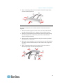
Note: The Raritan device depicted in the rack mounting diagrams is for
example purposes only and may not depict your device. The mounting
instructions are specific to your device.
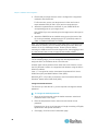
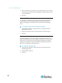
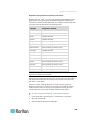
Forward Mount
The steps correspond to the numbers shown in the front rackmount
diagrams.
1. Secure the cable-support bar to the back end of the side brackets
using two of the included screws.
2. Slide the KX II between the side brackets, with its rear panel facing
the cable-support bar, until its front panel is flush with the “ears” of
the side brackets.
3. Secure the KX II to the side brackets using the remaining included
screws (three on each side).
4. Mount the entire assembly in your rack, and secure the side
brackets' ears to the rack's front rails with your own screws, bolts,
cage nuts, and so on.
10
Chapter 2: Installation and Configuration
5. When connecting cables to the rear panel of the KX II drape them
over the cable-support bar.
Rear Mount
The steps correspond to the numbers shown in the rear rackmount
diagrams.
1. Secure the cable-support bar to the front end of the side brackets,
near the side brackets' “ears,” using two of the included screws.
2. Slide the KX II between the side brackets, with its rear panel facing
the cable-support bar, until its front panel is flush with the back
edges of the side brackets.
3. Secure the KX II to the side brackets using the remaining included
screws (three on each side).
4. Mount the entire assembly in your rack and secure the side brackets'
ears to the rack's front rails with your own screws, bolts, cage nuts,
and so on.
5. When connecting cables to the rear panel of the user station or
switch, drape them over the cable-support bar.
11
Chapter 2: Installation and Configuration
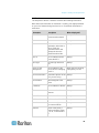
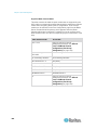
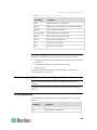
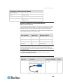
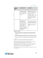
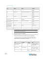
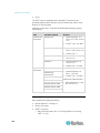
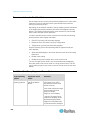
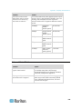
Default Login Information
Default
Value
User name
admin
This user has administrative privileges.
Password
raritan
The first time you start the KX II, you are required to
change the default password.
IP address
192.168.0.192.
Important: For backup and business continuity purposes, it is strongly
recommended that you create a backup administrator user name and
password and keep that information in a secure location.
Getting Started
Note that the following configuration requirements apply only to the
target server, not to the computers that you remotely access the KX II.
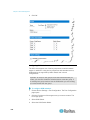
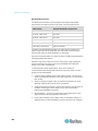
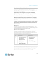
Step 1: Configuring Network Firewall Settings
TCP Port 5000
Allow network and firewall communication on TCP Port 5000 to enable
remote access to the KX II.
Alternatively, configure the KX II to use a different TCP port, then allow
communication on that port.
TCP Port 443
Allow access to TCP Port 443 (Standard HTTPS) so you can access KX
II via a web browser.
TCP Port 80
Allow access to TCP Port 80 (Standard HTTP) to enable automatic
redirection of HTTP requests to HTTPS.
12
Chapter 2: Installation and Configuration
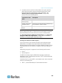
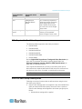
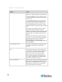
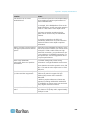
Step 2: Configure the KVM Target Servers
Target Server Video Resolutions
For optimal bandwidth efficiency and video performance, KVM target
servers running graphical user interfaces such as Windows ®, Linux®,
X-Windows, Solaris™, and KDE may require configuration.
The desktop background does not need to be completely solid, but
desktop backgrounds featuring photos or complex gradients might
degrade performance.
Ensure that the server video resolution and refresh rate are supported by
KX II, and that the signal is non-interlaced.
See the KX II Online Help for a list of supported target server video
resolutions.
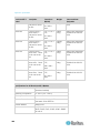
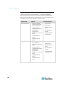
Mouse Settings
Following are the mouse settings for various operating systems.
These settings are configured on your target operating system unless
otherwise indicated.
See the KX II Online Help for details on configuring these mouse
settings.
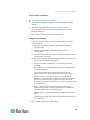
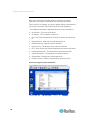
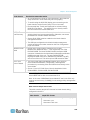
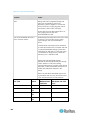
Windows 7 and Windows Vista Mouse Settings
Configure these mouse settings in Windows 7® and Windows
Vista®:
Configure the motion settings:
Set the mouse motion speed setting to exactly the middle speed
Disable the "Enhanced pointer precision" option
Disable animation and fade effects:
Animate controls and elements inside windows
Animate windows when minimizing and maximizing
Fade or slide menus into view
Fade or slide ToolTips into view
Fade out menu items after clicking
13
Chapter 2: Installation and Configuration
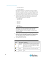
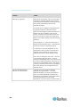
Windows XP, Windows 2003, Windows 2008 Mouse Settings
Configure these mouse settings in Windows XP®, Windows
2003® and Windows 2008®:
Configure the Motion settings:
Set the mouse motion speed setting to exactly the middle speed
Disable the "Enhance pointer precision" option
Disable the Snap To option
Disable transition effects:
Deselect the "Use the following transition effect for menus and
tooltips" option
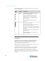
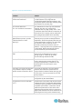
Windows 2000 Mouse Settings
Configure these Windows 2000® mouse settings:
Configure the Motion settings:
Set the acceleration to None
Set the mouse motion speed setting to exactly the middle speed
Disable transition effects:
Deselect the "Use the following transition effect for menus and
tooltips" option
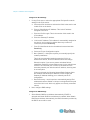
Apple Mac Mouse Settings
Configure these Apple Mac® mouse settings:
Absolute Mouse Synchronization is required for proper mouse
synchronization on KVM target servers running a Mac® operating system.
In order for Absolute Mouse Synchronization to work, a virtual media
CIM is required. For a list of supported CIMs, see Supported Computer
Interface Module (CIMs) Specifications.
Once you have completed your KX II installation, set the Mac USB profile.
If you do not set this profile, the mouse does synch in OS X.
To do this, do one of the following:
1. Connect to the Mac target from the Raritan KVM Client.
2. Select USB Profile > Other Profiles > Mac OS-X (10.4.9 and later).
Or
14
Chapter 2: Installation and Configuration
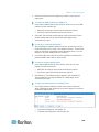
3. In KX II, select Device Settings > Port Configuration, then click on
the target name to open the Port page.
4. Expand 'Select USB Profiles for Port' section.
5. Select 'Mac OS-X (10.4.9) and later' from the Available box, then
click Add to add it to the Selected box.
6. Click on 'Mac OS-X (10.4.9) and later' in the Selected box. This
automatically adds it to the Preferred Profile drop-down.
7. Select 'Mac OS-X (10.4.9) and later' from the Preferred Profile
drop-down, then check the checkbox under 'Set Active Profile As
Preferred Profile'.
Click OK to apply.
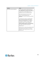
Linux Mouse Settings
Configure these Linux® mouse settings:
(Standard Mouse Mode only) Set the mouse acceleration to exactly
1 and set the threshold to exactly 1. Enter the following command:
xset mouse 1 1. This should be set for execution upon login.
Sun Solaris Mouse Settings
Configure these Sun® Solaris™ mouse settings:
Set the mouse acceleration value to exactly 1 and the threshold to
exactly 1
Ensure that your video card is set to a supported resolution and that
its output is VGA, not composite sync
IBM AIX Mouse Settings
Configure these IBM AIX® mouse settings:
Go to the Style Manager, click on Mouse Settings and set Mouse
Acceleration to 1.0 and Threshold to 3.0
15
Chapter 2: Installation and Configuration
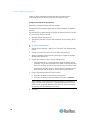
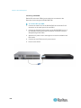
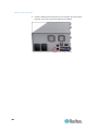
Step 3: Connect the Equipment
A. AC Power
Connect the power supply(s):
1. Attach the included AC power cord to the KX II, and plug it into an
AC power outlet.
2. For dual-power failover protection, attach the second included AC
power cord to the KX II, and plug it into a different power source than
the first power cord.
B. Modem Port (Optional)
Please see the KX II Online Help for information on connecting
modems.
C. Network Port
The KX II provides two Ethernet ports for failover purposes - not for
load-balancing.
By default, only LAN1 is active, and the automatic failover is disabled.
Enable network failover if you want LAN2 to use the same IP address
should the KX II internal network interface or the network switch it is
connected to become unavailable.
To connect to the network:
1. Connect a standard Ethernet cable from the network port labeled
LAN1 to an Ethernet switch, hub, or router.
2. To use the optional KX II Ethernet failover capabilities:
a. Connect a standard Ethernet cable from the network port labeled
LAN2 to an Ethernet switch, hub, or router.
16
Chapter 2: Installation and Configuration
Enable 'Automatic Failover' on the KX II Network Configuration page.
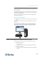
D. Local Access Port (Local PC)
For access to target servers at the rack, use the KX II Local Access port.
The Local Access port also provides a graphical user interface from the
KX II Local Console for administration and target server access.
While the Local Access port is required for installation and setup, it is
optional for subsequent use.
Note: The KX2-808, KX2-832 and KX2-864 also provide an Extended
Local port labeled EXT LOCAL on the back of the device for access to
target servers while at the rack. The Extended Local port is not required
for the initial installation and setup. It is not enabled by default and is
configured from the Local Console and the Remote Console.
To connect the local port:
Attach a multi-sync VGA monitor, mouse, and keyboard to the
respective Local User ports using USB keyboard and mouse. The
Local User and Extended Local ports are on the back panel of the
KX II.
Monitor - attach a standard multi-sync VGA monitor to the HD15
(female) video port
Keyboard - attach either a standard keyboard to the Mini-DIN6
(female) keyboard port, or a standard USB keyboard to one of the
USB Type A (female) ports
Mouse - attach either a standard mouse to the Mini-DIN6 (female)
mouse port, or a standard USB mouse to one of the USB Type A
(female) ports
E. Target Server Ports
The KX II uses standard UTP cabling (Cat5/5e/6) to connect to each
target server.
For information on the supported distances between the KX II and target
server, see Supported Target Server Connection Distance/Refresh
Rate/Video Resolution in KX II Online Help.
If you are using digital CIMs (DCIMs), review Digital CIM Target Server
Timing and Video Resolution in KX II Online Help.
To connect a target server to the KX II:
1. Use the appropriate CIM or DCIM. Attach the video connector of
your CIM/DCIM to the video port of your target server.
17
Chapter 2: Installation and Configuration
2. Ensure that your target server's video is configured to a supported
resolution and refresh rate.
For Sun servers, ensure your target server's video card is set to
output standard VGA (H-and-V sync) and not composite sync.
3. Attach the keyboard/mouse connector of your CIM/DCIM to the
corresponding ports on your target server.
Use a DCIM if you are connecting from the target server video port to
the KX II.
4. Attach the CIM/DCIM to an available server port on the back of the
KX II using a standard, straight-through UTP (Cat5/5e/6) cable for
CIMs, or standard USB cable for DCIMs.
Note: The DCIM-USB G2 provides a small slide switch on the back of the
CIM. Move the switch to P for PC-based USB target servers. Move the
switch to S for Sun USB target servers. Power-cycle the CIM by
removing the USB connector from the target server, then plugging it back
in a few seconds later in order to apply the new switch position.
Step 4: Configure the KX II
For the following steps, you must change the default password and
assign the KX II its IP address at the Local Console.
All other steps can be performed from either the Local Console, or from
the KX II Remote Console via a supported web browser using the KX II's
default IP address.
Java™ 1.7 is required to use the Java-based Java-based KX II Virtual
KVM Client (VKC) and Multi-Platform Client (MPC)..
Microsoft .NET® 3.5 (or later) is required to use KX II with the Microsoft
Windows®-based Active KVM Client (AKC).
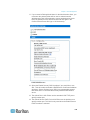
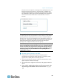
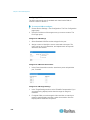
Change the Default Password
The first time you start the KX II, you are required to change the default
password.
To change the default password:
1. Once the unit has booted, enter the default username admin and
password raritan. Click Login.
2. Enter the old password raritan, then enter and reenter a new
password.
Passwords can be up to 64 characters in length consisting of English,
alphanumeric and special characters.
3. Click Apply. Click OK on the Confirmation page.
18
Chapter 2: Installation and Configuration
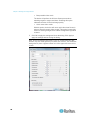
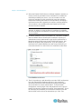
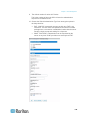
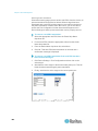
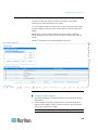
Assign the KX II an IP Address
To assign an IP address to the KX II:
1. Choose Device Settings > Network. The Network Settings page
opens.
2. Specify a meaningful Device Name for your KX II device.
Up to 32 alphanumeric and valid special characters, no spaces
between characters.
3. Next, configure the IPv4, IPv6 and DNS settings.
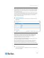
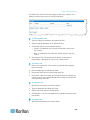
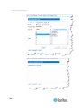
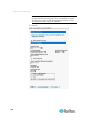
Configure the IPv4 Settings
1. In the IPv4 section, enter or select the appropriate IPv4-specific
network settings:
a. Enter the IP Address if needed. The default IP address is
192.168.0.192.
b. Enter the Subnet Mask. The default subnet mask is
255.255.255.0.
c.
Enter the Default Gateway if None is selected from the IP Auto
Configuration drop-down.
d. Enter the Preferred DHCP Host Name if DHCP is selected from
the IP Auto Configuration drop-down.
e. Select the IP Auto Configuration. The following options are
available:
None (Static IP) - This option requires you manually specify the
network parameters.
This is the recommended option because the KX II is an
infrastructure device, and its IP address should not change.
Select this option if you want to ensure redundant failover
capabilities should the primary Ethernet port (or the switch/router
to which it is connected) fail. If it fails, KX III fails over to the
secondary network port with the same IP address, ensuring there
is not interruption.
DHCP - Dynamic Host Configuration Protocol is used by
networked computers (clients) to obtain unique IP addresses
and other parameters from a DHCP server.
With this option, network parameters are assigned by the DHCP
server.
If DHCP is used, enter the Preferred host name (DHCP only). Up
to 63 characters.
2. Next, configure IPv6 and/or DNS settings.
19
Chapter 2: Installation and Configuration
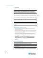
Configure the IPv6 Settings
1. If using IPv6, enter or select the appropriate IPv6-specific network
settings in the IPv6 section:
a. Select the IPv6 checkbox to activate the fields in the section and
enable IPv6 on the device.
b. Enter a Global/Unique IP Address. This is the IP address
assigned to the KX II.
c.
Enter the Prefix Length. This is the number of bits used in the
IPv6 address.
d. Enter the Gateway IP Address.
e. Link-Local IP Address. This address is automatically assigned to
the device, and is used for neighbor discovery or when no
routers are present. Read-Only
f.
Zone ID. Identifies the device the address is associated with.
Read-Only
g. Select an IP Auto Configuration option:
None (Static IP) - this option requires you manually specify the
network parameters.
This is the recommended option because the KX II is an
infrastructure device, and its IP address should not change.
Select this option if you want to ensure redundant failover
capabilities should the primary Ethernet port (or the switch/router
to which it is connected) fail. If it fails, KX III switches to the
secondary network port with the same IP address, ensuring their
is no interruption.
If None is selected, the following Network Basic Settings fields
are enabled: Global/Unique IP Address, Prefix Length, and
Gateway IP Address allowing you to manually set the IP
configuration.
Router Discovery - use this option to automatically assign IPv6
addresses that have Global or Unique Local significance beyond
that of the Link Local, which only applies to a directly connected
subnet.
2. Next, configure DNS settings.
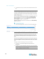
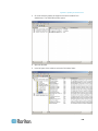
Configure the DNS Settings
1. Select Obtain DNS Server Address Automatically if DHCP is
selected and Obtain DNS Server Address is enabled. When Obtain
DNS Server Address Automatically, the DNS information provided by
the DHCP server will be used.
20
Chapter 2: Installation and Configuration
2. If Use the Following DNS Server Addresses is selected, whether or
not DHCP is selected, the addresses entered in this section is used
to connect to the DNS server.
Enter the following information if the Following DNS Server
Addresses is selected. These addresses are the primary and
secondary DNS addresses used if the primary DNS server
connection is lost due to an outage.
a. Primary DNS Server IP Address
b. Secondary DNS Server IP Address
3. When finished, click OK.
Your KX II device is now network accessible.
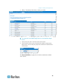
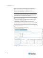
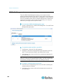
Name Your Target Servers
To name the target servers:
1. Connect all of the target servers if you have not already done so.
2. Select Device Settings > Port Configuration, then click the Port
Name of the target server you want to name.
3. Enter a name for the server up to 32 alphanumeric and special
characters. Click OK.
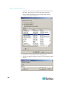
Specify Power Supply Autodetection
The KX II provides dual power supplies.
When both power supplies are used, the KX II automatically detects
them and notifies you of their status.
Additionally, both the Powerln1 and Powerln2 Auto Detect checkboxes
are automatically selected on the Power Supply Setup page.
If you are using only one power supply, you can enable automatic
detection for only the power supply in use.
To enable automatic detection for the power supply in use:
1. Choose Device Settings > Power Supply Setup. The Power Supply
Setup page opens.
2. If you are plugging power input into power supply number one
(left-most power supply at the back of the device), select the
Powerln1 Auto Detect option.
3. If you are plugging power input into power supply number two
(right-most power supply at the back of the device), select the
Powerln2 Auto Detect option. Click OK.
21
Chapter 2: Installation and Configuration
If either of these checkboxes is selected and only power input is
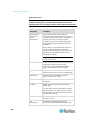
connected, the power LED on the front of the device is Red.
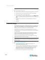
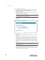
Configure Date/Time Settings (Optional)
Optionally, configure the date and time settings.
The date and time settings impact SSL certificate validation if LDAPS is
enabled.
Use the Date/Time Settings page to specify the date and time for the KX
II. There are two ways to do this:
Manually set the date and time.
Synchronize the date and time with a Network Time Protocol (NTP)
server.
To set the date and time:
1. Choose Device Settings > Date/Time. The Date/Time Settings page
opens.
2. Choose your time zone from the Time Zone drop-down list.
3. Adjust for daylight savings time by checking the "Adjust for daylight
savings time" checkbox.
4. Choose the method to use to set the date and time:
User Specified Time - use this option to input the date and time
manually. For the User Specified Time option, enter the date and
time. For the time, use the hh:mm format (using a 24-hour clock).
Synchronize with NTP Server - use this option to synchronize the
date and time with the Network Time Protocol (NTP) Server.
5. For the Synchronize with NTP Server option:
a. Enter the IP address of the Primary Time server.
b. Enter the IP address of the Secondary Time server. Optional
Note: If DHCP is selected for the Network Settings on the Network
page, the NTP server IP address is automatically retrieved from the
DHCP server by default. Manually enter the NTP server IP address
by selecting the Override DHCP checkbox.
6. Click OK.
22
Chapter 2: Installation and Configuration
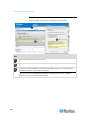
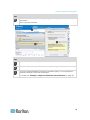
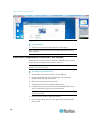
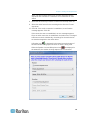
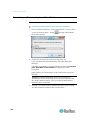
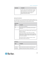
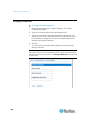
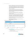
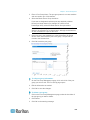
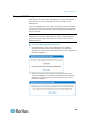
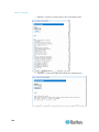
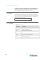
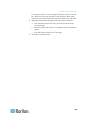
Step 5: Launching the KX II Remote Console
Log in to your KX II Remote Console from any workstation with network
connectivity that has Microsoft .NET ® and/or Java Runtime Environment™
installed.
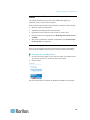
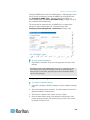
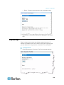
To launch the KX II Remote Console:
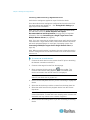
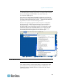
1. Launch a supported web browser.
2. Enter either:
The URL - http://IP-ADDRESS to use the Java-based Virtual
KVM Client
Or
http://IP-ADDRESS/akc for the Microsoft .NET-based Active KVM
Client
IP-ADDRESS is the IP address assigned to your KX II
You can also use HTTPS, or the DNS name of the KX II assigned by
your administrator (if applicable).
3. You are always redirected to the IP address from HTTP to HTTPS.
4. Enter your username and password. Click Login.
Access and Control Target Servers Remotely
The KX II Port Access page provides a list of all KX II ports, as well as
the connected target servers, their status, and availability.
Accessing a Target Server
To access a target server:
1. On the KX II Port Access page, click the Port Name of the target you
want to access.
The Port Action Menu is displayed.
2. Choose Connect from the Port Action menu.
A KVM window opens with a connection to the target.
Switching between Target Servers
To switch between KVM target servers:
1. While already using a target server, access the KX II Port Access
page.
2. Click the port name of the target you want to access. The Port Action
menu appears.
23
Chapter 2: Installation and Configuration
3. Choose Switch From in the Port Action menu. The new target server
you selected is displayed.
Disconnecting a Target Server
To disconnect a target server:
On the Port Access page, click the port name of the target you want
to disconnect from, then click Disconnect on Port Action menu when
it appears.
Step 6: Configuring the Keyboard Language (Optional)
Note: This step is not required if you are using the US/International
language keyboard.
If you are using a non-US language, the keyboard must be configured for
the appropriate language.
Additionally, the keyboard language for the client machine and the KVM
target servers must match.
Consult your operating system documentation for additional information
about changing the keyboard layout.
Changing the Keyboard Layout Code (Sun Targets)
Use this procedure if you are using a DCIM-SUSB and want to change
the keyboard layout to another language.
To change the keyboard layout code (DCIM-SUSB only):
1. Open a Text Editor window on the Sun™ workstation.
2. Check that the Num Lock key is active. then press the left Ctrl key
and the Del key on your keyboard, or select the option "set CIM
keyboard/Mouse options" from the keyboard menu.
The Caps Lock light starts to blink, indicating that the CIM is in
Layout Code Change mode.
The text window displays: Raritan Computer, Inc. Current
keyboard layout code = 22h (US5 UNIX).
3. Type the layout code desired (for example, 31 for the Japanese
keyboard). Press Enter.
4. Shut down the device and power on once again. The DCIM-SUSB
performs a reset (power cycle).
5. Verify that the characters are correct.
24
Chapter 2: Installation and Configuration
Step 7: Configure Tiering (Optional)
The optional tiering feature allows you to use a KX II as your base device,
then connect additional KX II's to it as tiered devices.
You can then access servers and PX PDUs through the base both locally
and remotely. See the Device Management (on page 141) section of
the KX II Help for more information on this feature.
To enable tiering:
1. From the base KX II tier device, select Device Settings > Device
Services to open the Device Service Settings page.
2. Select Enable Tiering as Base.
3. In the Base Secret field, enter the secret shared between the base
and the tiered devices. This secret is required for the tiered devices
to authenticate the base device. Enter the same secret word for the
tiered device. Click OK.
4. Enable the tiered devices. From the tiered device, choose Device
Settings > Local Port Settings.
5. In the Enable Local Ports section of the page, select Enable Local
Port Device Tiering.
6. In the Tier Secret field, enter the same secret word you entered for
the base device on the Device Settings page. Click OK.
Logging in to the KX II
Log in to your KX II Remote Console from any workstation with network
connectivity. Java™ 1.7 is required to use the Java-based Java-based
Virtual KVM Client (VKC) and Multi-Platform Client (MPC). Alternatively,
Microsoft .NET® 3.5 (or later) is required to use KX II with the Microsoft
Windows®-based Active KVM Client (AKC).
Logging in and using KX II requires you to allow pop-ups.
For information on security warnings and validation messages, and steps
to reduce or eliminate them, see Security Warnings and Validation
Messages (on page 26).
To log in to the KX II:
1. Launch a supported web browser.
2. Enter either:
The URL - http://IP-ADDRESS to use the Java-based Virtual
KVM Client
Or
25
Chapter 2: Installation and Configuration
http://IP-ADDRESS/akc for the Microsoft .NET-based Active KVM
Client
IP-ADDRESS is the IP address assigned to your KX II
You can also use HTTPS, or the DNS name of the KX II assigned by
your administrator (if applicable).
You are always redirected to the IP address from HTTP to HTTPS.
3. Enter your username and password, then click Login.
4. Accept the user agreement (if applicable).
5. If security warnings appear, accept and/or allow access.
Allow Pop-Ups
Regardless of the browser used, you must allow pop-ups from the
device's IP address to launch the KX II Remote Console.
Security Warnings and Validation Messages
When logging in to KX II, security warnings and application validation
message may appear.
These include:
Java™ security warnings and requests to validate KX II. See Java
Validation and Access Warning (on page 26), and Installing a
Certificate (on page 27)
Additional security warnings based on your browser and security
settings. See Additional Security Warnings (on page 27)
Java Validation and Access Warning
When logging in to KX II, Java™ 1.7 prompts you to validate KX II, and to
allow access to the application.
Raritan recommends installing an SSL certificate in each KX II device in
order to reduce Java warnings, and enhance security. See SSL
Certificates (on page 234)
26
Chapter 2: Installation and Configuration
Additional Security Warnings
Even after an SSL certificate is installed in the KX II, depending on your
browser and security settings, additional security warnings may be
displayed when you log in to KX II.
It is necessary to accept these warnings to launch the KX II Remote
Console.
Reduce the number of warning messages during subsequent log ins by
checking the following options on the security and certificate warning
messages:
In the future, do not show this warning
Always trust content from this publisher
Installing a Certificate
You may be prompted by the browser to accept and validate the KX II's
SSL certificate.
Depending on your browser and security settings, additional security
warnings may be displayed when you log in to KX II.
It is necessary to accept these warnings to launch the KX II Remote
Console. For more information, see Security Warnings and Validation
Messages (on page 26).
Two sample methods on how to install an SSL Certificate in the browser
are provided here, both using Microsoft Internet Explorer 8® and
Windows 7®.
Specific methods and steps depend on your browser and operating
system. See your browser and operating system help for details.
27
Chapter 2: Installation and Configuration
Example 1: Import the Certificate into the Browser
In this example, you import the Certificate into the browser.
Steps
Open an IE browser, then log in to KX II.
Click More Information on the first Java™ security warning.
Click View Certificate Details on the More Information dialog. You are prompted to
install the certificate. Follow the wizard steps.
Note: If you are not prompted by the browser, manually select Tools > Internet
Options to open the Internet Options dialog.
28
Chapter 2: Installation and Configuration
Steps
Click the Content tab.
Click Certificates.
The Certificate Import Wizard opens and walks you through each step.
File to Import - Browse to locate the Certificate
Certificate Store - Select the location to store the Certificate
Click Finish on the last step of the Wizard.
The Certificate is imported. Close the success message.
Click OK on the Internet Options dialog to apply the changes, then close and reopen
the browser.
29
Chapter 2: Installation and Configuration
Example 2: Add the KX II to Trusted Sites and Import the Certificate
In this example, the KX II's URL is added as a Trusted Site, and the Self
Signed Certificate is added as part of the process.
Steps
Open an IE browser, then select Tools > Internet Options to open the Internet Options
dialog
Click the Security tab.
Click on Trusted Sites.
Disable Protected Mode, and accept any warnings.
Click Sites to open the Trusted Sites dialog.
Enter the KX II URL, then click Add.
Deselect server verification for the zone (if applicable).
Click Close.
30
Chapter 2: Installation and Configuration
Steps
Click OK on the Internet Options dialog to apply the changes, then close and reopen
the browser.
Next, import the Certificate.
Steps
Open an IE browser, then log in to KX II.
Click More Information on the first Java™ security warning.
Click View Certificate Details on the More Information dialog. You are prompted to
install the certificate. Follow the wizard steps.
For details see, Example 1: Import the Certificate into the Browser (on page 28)
31
Chapter 3
Working with Target Servers
In This Chapter
KX II Interfaces ........................................................................................32
KX II Local Console Interface: KX II Devices ..........................................33
KX II Remote Console Interface ..............................................................33
Proxy Server Configuration for Use with MPC, VKC and AKC ...............50
Virtual KVM Client (VKC) and Active KVM Client (AKC) .........................52
Multi-Platform Client (MPC) .....................................................................94
KX II Interfaces
There are several user interfaces in the KX II, providing you with easy
access anytime, anywhere to targets.
These include the KX II Local Console, the KX II Remote Console, the
Virtual KVM Client (VKC), the Active KVM Client (AKC), and the
Multi-Platform Client (MPC).
The following table identifies these interfaces and their use for target
server access and administration locally and remotely:
User interface
Local
access
Admin
Remote
access
Admin
KX II Local Console
KX II Remote Console
Virtual KVM Client (VKC)
Multi-Platform Client
(MPC)
Active KVM Client (AKC)
The following sections of the help contain information about using
specific interfaces to access the KX II and manage targets:
Local Console
Remote Console
Virtual KVM Client
Multi-Platform Client
32
Chapter 3: Working with Target Servers
KX II Local Console Interface: KX II Devices
When you are located at the server rack, the KX II provides standard
KVM management and administration via the KX II Local Console. The
KX II Local Console provides a direct KVM (analog) connection to your
connected servers; the performance is exactly as if you were directly
connected to the server's keyboard, mouse, and video ports.
There are many similarities among the KX II Local Console and the KX II
Remote Console graphical user interfaces. Where there are differences,
they are noted in the help.
The KX II Local Console Factory Reset option is available in the KX II
Local Console but not the KX II Remote Console.
KX II Remote Console Interface
The KX II Remote Console is a browser-based graphical user interface
that allows you to log in to KVM target servers and serial targets
connected to the KX II and to remotely administer the KX II.
The KX II Remote Console provides a digital connection to your
connected KVM target servers. When you log into a KVM target server
using the KX II Remote Console, a Virtual KVM Client window opens.
There are many similarities among the KX II Local Console and the KX II
Remote Console graphical user interfaces, and where there are
differences, they are noted in the user manual. The following options are
available in the KX II Remote Console but not the KX II Local Console:
Virtual Media
Favorites
Backup/Restore
Firmware Upgrade
SSL Certificates
Audio
33
Chapter 3: Working with Target Servers
KX II Interface
Both the KX II Remote Console and the KX II Local Console interfaces
provide a web-based interface for device configuration and
administration, as well as target server list and selection. The options are
organized into various tabs.
After a successful login, the Port Access page opens listing all ports
along with their status and availability. Four tabs are provided on the
page allowing you to view by port, view by group or view by search. You
can sort by Port Number, Port Name, Status (Up and Down), and
Availability (Idle, Connected, Busy, Unavailable, and Connecting) by
clicking on the column heading. See Port Access Page (Remote
Console Display) (on page 38) for more information.
Use the Set Scan tab to scan for up to 32 targets that are connected to
the KX II. See Scanning Ports (on page 47).
34
Chapter 3: Working with Target Servers
Left Panel
The left panel of the KX II interface contains the following information.
Note that some information is conditional - meaning it is displayed based
on your role, features being used and so on. Conditional information is
noted here.
Information
Description
When displayed?
Time & Session
The date and time the
current session started
Always
User
Username
Always
State
The current state of the
application, either idle or
active. If idle, the
application tracks and
displays the time the
session has been idle.
Always
Your IP
The IP address used to
access the KX II
Always
Last Login
The last login date and
time
Always
Under CC-SG
Management
The IP address of the
CC-SG device managing
the KX II
When the KX II is being
managed by CC-SG
Device Information
Information specific to the Always
KX II you are using
Device Name
Name assigned to the
device
IP Address
The IP address of the KX Always
II
Firmware
Current version of
firmware
Always
Device Model
Model of the KX II
Always
Serial number
Serial number of the KX II Always
Network
The name assigned to
the current network
Always
PowerIn1
Status of the power 1
outlet connection. Either
on or off, or Auto-detect
off
Always
Always
35
Chapter 3: Working with Target Servers
Information
Description
When displayed?
PowerIn2
Status of the power 2
outlet connection. Either
on or off, or Auto-detect
off
Always
Configured As
If you are using a tiering When the KX II is part of
Base or Configured configuration, this
a tiered configuration
indicates if the KX II you
As Tiered
are accessing is the base
device or a tiered device.
Port States
The statuses of the ports
being used by the KX II
Always
Connect Users
The users, identified by
Always
their username and IP
address, who are
currently connected to the
KX II
Online Help
Links to online help
Always
FIPS Mode
FIPS Mode: EnabledSSL
Certificate: FIPS Mode
Compliant
When FIPS is enabled
Favorite Devices
See Managing Favorites When enabled
(on page 43)
The left panel can be collapsed in order to increase the display area of
the page.
To collapse the left panel:
36
Click on the blue, left-facing arrow located approximately halfway
down the left side of the panel. Once the panel is collapsed, click the
blue arrow again to expand it.
Chapter 3: Working with Target Servers
KX II Console Navigation
The KX II Console interfaces provide many methods for navigation and
making your selections.
To select an option (use any of the following):
Click on a tab. A page of available options appears.
Hover over a tab and select the appropriate option from the menu.
Click the option directly from the menu hierarchy displayed
(breadcrumbs).
To scroll through pages longer than the screen:
Use Page Up and Page Down keys on your keyboard.
Use the scroll bar on the right.
37
Chapter 3: Working with Target Servers
Port Access Page (Remote Console Display)
After successfully logging on to the KX II remote console, the View by
Port tab on the Port Access page appears. This page lists all of the KX II
ports, and the target servers, port groups, and blade chassis that are
connected to those ports.
The information is sorted by Port Number by default, but you can change
the display to sort on any of the available columns by clicking on a
column header. To increase or decrease the number of rows displayed
on a tab at one time, enter the number of row in the Rows per Page field
and click Set.
The following information for each port is contained on this page:
Port Number - Numbered from 1 to the total number of ports
available for the KX II device.
Note: Ports connected to power strips are not listed, resulting in gaps
in the Port Number sequence.
Port Name - The name of the KX II port. Initially, this is set to
Dominion-KX2-Port# but you can change the name to something
more descriptive. When you click a Port Name link, the Port Action
Menu appears.
Note: Do not use apostrophes for the Port (CIM) Name.
Type - The type of server or CIM/DCIM.
For blade chassis, the type can be Blade Chassis, Blade,
BladeChassisAdmin, and BladeChassisURL.
Dual video port groups appear on the Port Access page as Dual Port
types.
The primary and secondary ports that are a part of the port group
appear on the Port Access page as Dual Port(P) and Dual Port(S),
respectively. For example, if the CIM type is DCIM, "DCIM Dual Port
(P)" is displayed.
38
Chapter 3: Working with Target Servers
Status - The status of the servers - either up or down.
To connect to an available target server or dual monitor target
server:
1. Click on the port name. The Port Action menu opens.
2. Click Connect. Once you are connected to a target or dual monitor
target server, click on the port group name and then click Disconnect
to disconnect.
See Port Action Menu (on page 41) for details on additional available
menu options.
39
Chapter 3: Working with Target Servers
View by Group Tab
The View by Group tab displays blade chassis, 'standard' port groups,
and dual video port groups. Click the Expand Arrow icon
next to a
group to view the ports assigned to the port group.
See Device Management (on page 141) for information on creating
each of these types of port groups.
View by Search Tab
The View by Search tab allows you to search by port name. The search
feature supports the use of an asterisk (*) as a wildcard, and full and
partial names.
Set Scan Tab
The port scanning feature is accessed from the Set Scan tab on the Port
Access page. The feature allows you to define a set of targets to be
scanned. Thumbnail views of the scanned targets are also available.
Select a thumbnail to open that target in its Virtual KVM Client window.
See See Scanning Ports - Remote Console for more information.
Tiered Devices - Port Access Page
If you are using a tiered configuration in which a base KX II device is
used to access multiple other tiered devices, the tiered devices are
viewed on the Port Access page by clicking on the Expand Arrow icon
to the left of the tier device name. See Configuring and Enabling
Tiering (on page 147) for more information on tiering.
40
Chapter 3: Working with Target Servers
Blade Chassis - Port Access Page
The blade chassis is displayed in an expandable, hierarchical list on the
Port Access page, with the blade chassis at the root of the hierarchy and
the individual blades labeled and displayed below the root. Use the
Expand Arrow icon
next to the root chassis to display the individual
blades.
Note: To view the blade chassis in a hierarchal order, blade-chassis
subtypes must be configured for the blade server chassis.
Dual Port Video Groups - Port Access Page
Dual video port groups appear on the Port Access page as Dual Port
types.
The primary and secondary ports that are a part of the port group appear
on the Port Access page as Dual Port(P) and Dual Port(S), respectively.
For example, if the CIM type is DCIM, "DCIM Dual Port (P)" is displayed.
When you access a dual port video group from the remote client, you
connect to the primary port, which opens a KVM connection window to
both the primary and secondary ports of the dual port group.
Note: The dual video primary port is defined when the port group is
created.
Note: Two KVM channels are required to remotely connect to the dual
video port group by clicking primary port. If two channels are not
available, the Connect link is not displayed.
Note: The Action menu is not displayed when you click on a secondary
port in a dual video port group.
Note: You cannot connect to the primary port and secondary port at the
same time from the Local Port.
Port Action Menu
When you click a Port Name in the Port Access list, the Port Action menu
appears.
Choose the desired menu option for that port to execute it. Note that only
currently available options, depending on the port's status and availability,
are listed in the Port Action menu.
Connect - Creates a new connection to the target server.
For the KX II Remote Console, a new Virtual KVM Client page
appears.
For the KX II Local Console, the display switches to the target server,
and switches away from the local user interface.
41
Chapter 3: Working with Target Servers
On the local port, the KX II Local Console interface must be visible in
order to perform the switch.
Hot key switching is also available from the local port.
Note: This option is not available from the KX II Remote Console for
an available port if all connections are busy.
Switch From - Switches from an existing connection to the selected
port (KVM target server).
This menu item is available only for KVM targets, and only when a
Virtual KVM Client is opened.
Note: This menu item is not available on the KX II Local Console.
Disconnect - Disconnects this port and closes the Virtual KVM Client
page for this target server.
This menu item is available only when the port status is up and
connected, or up and busy.
Note: This menu item is not available on the KX II Local Console.
The only way to disconnect from the switched target in the Local
Console is to use the hot key.
Power On - Powers on the target server through the associated
outlet.
This option is visible only when there are one or more power
associations to the target, and when the user has permission to
operate this service.
Power Off - Powers off the target server through the associated
outlets.
This option is visible only when there are one or more power
associations to the target, when the target power is on (port status is
up), and when user has permission to operate this service.
Power Cycle - Power cycles the target server through the associated
outlets.
This option is visible only when there are one or more power
associations to the target, and when the user has permission to
operate this service.
42
Chapter 3: Working with Target Servers
Managing Favorites
A Favorites feature is provided so you can organize and quickly access
the devices you use frequently.
The Favorite Devices section is located in the lower left side (sidebar) of
the Port Access page and provides the ability to:
Create and manage a list of favorite devices
Quickly access frequently-used devices
List your favorites either by Device Name, IP Address, or DNS
hostname
Discover KX II devices on its subnet (before and after login)
Retrieve discovered KX II devices from the connected Dominion
device (after login)
43
Chapter 3: Working with Target Servers
Enable Favorites
Click Enable in the Favorite Devices section of the left panel of the
KX II interface.
Once enabled, the Enable button becomes a Disable button.
44
Chapter 3: Working with Target Servers
Access and Display Favorites
To access a favorite KX II device:
Click the device name (listed beneath Favorite Devices). A new
browser opens to that device.
To display favorites by name:
Click Display by Name.
To display favorites by IP Address:
Click Display by IP.
To display favorites by the host name:
Click Display by Host Name.
Discovering Devices on the Local Subnet
This option discovers the devices on your local subnet, which is the
subnet where the KX II Remote Console is running. These devices can
be accessed directly from this page or you can add them to your list of
favorites. See Favorites List Page.
To discover devices on the local subnet:
1. Choose Manage > Discover Devices - Local Subnet. The Discover
Devices - Local Subnet page appears.
2. Choose the appropriate discovery port:
45
Chapter 3: Working with Target Servers
To use the default discovery port, select the Use Default Port
5000 checkbox.
To use a different discovery port:
a. Deselect the Use Default Port 5000 checkbox.
b. Type the port number in the Discover on Port field.
c.
Click Save.
3. Click Refresh. The list of devices on the local subnet is refreshed.
To add devices to your Favorites List:
1. Select the checkbox next to the device name/IP address.
2. Click Add.
To access a discovered device:
Click the device name or IP address for that device. A new browser
opens to that device.
Discovering Devices on the KX II Subnet
This option discovers devices on the device subnet, which is the subnet
of the KX II device IP address itself. You can access these devices
directly from this the Subnet page or add them to your list of favorites.
See Favorites List Page.
This feature allows multiple KX II devices to interoperate and scale
automatically. The KX II Remote Console automatically discovers the KX
II devices, and any other Raritan device, in the subnet of the KX II.
To discover devices on the device subnet:
1. Choose Manage > Discover Devices - KX II Subnet. The Discover
Devices - KX II Subnet page appears.
2. Click Refresh. The list of devices on the local subnet is refreshed.
To add devices to your Favorites List:
1. Select the checkbox next to the device name/IP address.
2. Click Add.
To access a discovered device:
46
Click the device name or IP address for that device. A new browser
opens to that device.
Chapter 3: Working with Target Servers
Scanning Ports
The KX II provides the port scanning feature to search for selected
targets, and display them in a slide show view, allowing you to monitor
up to 32 targets at one time.
You can connect to targets or focus on a specific target as needed.
Scans can include standard targets, blade servers, tiered Dominion
devices, and KVM switch ports.
Configure scan settings from either the Virtual KVM Client (VKC) or
Active KVM Client (AKC).
Note: For dual video port groups, the primary port is included in a port
scan, but the secondary port is not included when connecting from a
remote client. Both ports can be included in the scan from the Local Port.
Dual video port groups are supported by the KX II 2.5.0 (and later).
Note: Scanning for tiered devices is not supported by the Multi-Platform
Client (MPC).
When you start a scan, the Port Scan window opens.
As each target is found, it is displayed as a thumbnail in a slide show.
The slide show scrolls through the target thumbnails based on the
default interval of 10 seconds or according to the interval you specify.
As the scan scrolls through the targets, the target that is the focus of the
slide show displays in the center of the page.
The name of the target is displayed below its thumbnail and in the task
bar at the bottom of the window.
If a target is busy, a blank screen is displayed instead of the target server
access page.
The status of each target is indicated by green, yellow and red lights that
are displayed below the target thumbnail and, as the target is the focus
of the rotation, in the task bar.
Lights for each target are gray until they are the focus of the slide show.
The status lights indicate the following:
Green - the target is up/idle or up/connected
Yellow - the target is down but connected
Red - the target is down/idle, busy, or otherwise not accessible
This feature is available from the Local Port, Virtual KVM Client (VKC),
Active KVM Client (AKC) and Multi-Platform Client (MPC).
47
Chapter 3: Working with Target Servers
Note: MPC uses a different method for initiating a scan than the other
Raritan clients. See Set Scan Group in the KVM and Serial Client
Guide for details. The scan results and scan options differ between the
Remote Console and the Local Console. See Scanning Ports - Local
Console (on page 269).
To scan for targets:
1. Click the Set Scan tab on the Port Access page.
2. Select the targets you want to include in the scan by selecting the
checkbox to the left of each target, or select the checkbox at the top
of the target column to select all targets.
3. Leave the Up Only checkbox selected if you only want targets that
are up to be included in the scan. Deselect this checkbox if you want
to include all targets, whether up or down.
4. Click Scan to begin the scan.
As each target is scanned, it is displayed in slide show view on the
page.
5. Click Options > Pause to pause the slide show and stop it from
moving between targets, click Options > Resume to resume the slide
show.
6. Click on a target thumbnail to scan it next.
7. Connect to a target by double clicking on its thumbnail.
48
Chapter 3: Working with Target Servers
Using Scan Port Options
Following are options available to you while scanning targets.
With the exception of the Expand/Collapse icon, all of these options are
selected from the Options menu in the upper left of the Port Scan viewer.
The options will return to their defaults when you close the window.
Note: Configure scan settings such as the display interval from either the
Virtual KVM Client (VKC) or Active KVM Client (AKC). See Configuring
Port Scan Settings in VKC and AKC
Hide or View Thumbnails
Use the Expand/Collapse icon
at the upper left of the window to
hide or view thumbnails. Expanded is the default view.
Pause the Thumbnail Slide Show
Pause thumbnails from rotating between one target and the next by
selecting Options > Pause. Rotating thumbnails is the default setting.
Resume the Thumbnail Slide Show
Resume the thumbnail rotation by selecting Options > Resume.
Size the Thumbnails in the Port Scan Viewer
Enlarge the size of the thumbnails by selecting Options > Size >
360x240.
Minimize the size of the thumbnails by selection Options > Size >
160x120. This is the default thumbnail size.
Change the Orientation of the Port Scan Viewer
View thumbnails along the bottom of the Port Scan viewer by
selecting Options > Split Orientation > Horizontal.
View thumbnails along the right of the Port Scan viewer by selecting
Options > Split Orientation > Vertical. This is the default view.
49
Chapter 3: Working with Target Servers
Logging Out
To quit the KX II:
Click Logout in the upper right-hand corner of the page.
Note: Logging out also closes any open Virtual KVM Client and serial
client sessions.
Proxy Server Configuration for Use with MPC, VKC and AKC
When the use of a Proxy Server is required, a SOCKS proxy must also
be provided and configured on the remote client PC.
Note: If the installed proxy server is only capable of the HTTP proxy
protocol, you cannot connect.
To configure the SOCKS proxy:
1. On the client, select Control Panel > Internet Options.
a. On the Connections tab, click 'LAN settings'. The Local Area
Network (LAN) Settings dialog opens.
b. Select 'Use a proxy server for your LAN'.
c.
Click Advanced. The Proxy Settings dialog opens.
d. Configure the proxy servers for all protocols. IMPORTANT: Do not
select 'Use the same proxy server for all protocols'.
Note: The default port for a SOCKS proxy (1080) is different from
HTTP proxy (3128).
2. Click OK at each dialog to apply the settings.
3. Next, configure the proxies for Java™ applets by selecting Control
Panel > Java.
50
Chapter 3: Working with Target Servers
e. On the General tab, click Network Settings. The Network Settings
dialog opens.
f.
Select Use Proxy Server.
g. Click Advanced. The Advanced Network Settings dialog opens.
h. Configure the proxy servers for all protocols. IMPORTANT: Do not
select 'Use the same proxy server for all protocols'.
Note: The default port for a SOCKS proxy (1080) is different from
HTTP proxy (3128).
4. If you are using standalone MPC, you must also do the following:
i.
Open the start.bat file in MPC directory with a text editor.
j.
Insert the following parameters to the command line. Add them
before "-classpath": -DsocksProxyHost=<socks proxy ip addr>
-DsocksProxyPort=<socks proxy port>
The parameters should look as follows:
start javaw -Xmn128M -Xmx512M -XX:MaxHeapFreeRatio=70
-XX:MinHeapFreeRatio=50 -Dsun.java2d.noddraw=true
-DsocksProxyHost=192.168.99.99 -DsocksProxyPort=1080
-classpath .\sdeploy.jar;.\sFoxtrot.jar;.\jaws.jar;.\sMpc.jar
com.raritan.rrc.ui.RRCApplication %1
51
Chapter 3: Working with Target Servers
Virtual KVM Client (VKC) and Active KVM Client (AKC)
Overview
Whenever you access a target server from the Port Access page of KX II
the Remote Console, a Virtual KVM Client (VKC) window opens.
There is one Virtual KVM Client for each target server connected.
Virtual KVM Client windows can be minimized, maximized, and moved
around your computer desktop.
IMPORTANT: Refreshing your browser closes the Virtual KVM
Client connection, so exercise caution.
Virtual KVM Client Java Requirements
Java™ 1.7 is required to use the Java-based Virtual VKM Client (VKC).
52
Chapter 3: Working with Target Servers
Virtual KVM Client (VKC) and Active KVM Client (AKC) Shared
Features
The Virtual KVM Client (VKC) and Active KVM Client (AKC) are
interfaces used to access remote targets.
VKC and AKC share similar features with the exception of the following:
Minimum system requirements
Supported operating systems and browsers
Keyboard macros created in AKC cannot be used in VKC
Direct port access configuration (see Enabling Direct Port Access
via URL)
AKC server certification validation configuration (see Prerequisites
for Using AKC (on page 93))
Connect to a Target Server
Once you have logged on to the KX II Remote Console, access target
servers via the Virtual KVM Client (VKC) or Active KVM Client (AKC).
To connect to an available server:
1. On the Port Access page, click on the port name of the target server
you want to connect to. The Port Action menu opens.
2. Click Connect.
See Port Action Menu for details on additional available menu options.
53
Chapter 3: Working with Target Servers
Connection Properties
Dynamic video compression algorithms maintain KVM console usability
under varying bandwidth constraints.
The devices optimize KVM output not only for LAN use, but also for WAN
use.
These devices can also control color depth and limit video output,
offering an optimal balance between video quality and system
responsiveness for any bandwidth.
The parameters in the Properties dialog can be optimized to suit your
needs for different operating environments. Connection properties are
saved across subsequent connections to generation 2 devices once they
are set and saved.
To set the connection properties:
1. Choose Connection > Properties or click the Connection Properties
button
in the toolbar. The Properties dialog appears.
2. Choose the Connection Speed from the drop-down list. The device
can automatically detect available bandwidth and not limit bandwidth
use. However, you can also adjust this usage according to
bandwidth limitations.
Auto
1G Ethernet
100 Mb Ethernet
10 Mb Ethernet
1.5 Mb (MAX DSL/T1)
1 Mb (Fast DSL/T1)
512 Kb (Medium DSL/T1)
384 Kb (Slow DSL/T1)
256 Kb (Cable)
128 Kb (Dual ISDN)
56 kb (ISP Modem)
33 kb (Fast Modem)
24 kb (Slow Modem)
Note that these settings are an optimization for specific conditions
rather than an exact speed. The client and server always attempt to
deliver video as quickly as possible on the network regardless of the
current network speed and encoding setting. But the system will be
most responsive when the settings match the real world environment.
54
Chapter 3: Working with Target Servers
3. Choose the Color Depth from the drop-down list. The device can
dynamically adapt the color depth transmitted to remote users in
order to maximize usability in all bandwidths.
15-bit RGB Color
8-bit RGB Color
4-bit Color
4-bit Gray
3-bit Gray
2-bit Gray
Black and White
Important: For most administrative tasks (server monitoring,
reconfiguring, and so on), the full 24-bit or 32-bit color spectrum
made available by most modern video graphics cards is not
necessary. Attempting to transmit such high color depths wastes
network bandwidth.
4. Use the slider to select the desired level of Smoothing (15-bit color
mode only). The level of smoothing determines how aggressively to
blend screen regions with small color variation into a single smooth
color. Smoothing improves the appearance of target video by
reducing displayed video noise.
5. Click OK to set these properties.
55
Chapter 3: Working with Target Servers
Connection Information
Open the Connection Information dialog for real-time connection
information, and copy the information from the dialog as needed.
This is useful if, for example, you want to gather real-time information on
your current connection. See Configuring Connection Properties
The following information is displayed about the current connection:
KX III Name - The name of the KX III.
IP Address - The IP address of the KX III.
Port - The KVM communication TCP/IP port used to access the KX
III.
Data In/Second - Data rate received from the KX III.
Data Out/Second - Data rate sent to the KX III.
Connect Time - The duration of the current connection.
FPS - Video frames per second transmitted received from the KX III.
Horizontal Resolution - The target server horizontal resolution.
Vertical Resolution - The target server vertical resolution.
Refresh Rate - Refresh rate of the target server.
Protocol Version - Raritan communications protocol version.
Access and Copy Connection Information
56
Chapter 3: Working with Target Servers
Steps
Click Connection > Info... to open the Connection Info dialog.
Click Copy to Clipboard. Paste the information in a file of your choosing.
Connection Properties
Dynamic video compression algorithms maintain KVM console usability
under varying bandwidth constraints.
The devices optimize KVM output not only for LAN use, but also for WAN
use.
These devices can also control color depth and limit video output,
offering an optimal balance between video quality and system
responsiveness for any bandwidth.
The parameters in the Properties dialog can be optimized to suit your
needs for different operating environments. Connection properties are
saved across subsequent connections to generation 2 devices once they
are set and saved.
To set the connection properties:
1. Choose Connection > Properties or click the Connection Properties
button
in the toolbar. The Properties dialog appears.
2. Choose the Connection Speed from the drop-down list. The device
can automatically detect available bandwidth and not limit bandwidth
use. However, you can also adjust this usage according to
bandwidth limitations.
Auto
1G Ethernet
100 Mb Ethernet
10 Mb Ethernet
1.5 Mb (MAX DSL/T1)
1 Mb (Fast DSL/T1)
512 Kb (Medium DSL/T1)
384 Kb (Slow DSL/T1)
256 Kb (Cable)
128 Kb (Dual ISDN)
56 kb (ISP Modem)
57
Chapter 3: Working with Target Servers
33 kb (Fast Modem)
24 kb (Slow Modem)
Note that these settings are an optimization for specific conditions
rather than an exact speed. The client and server always attempt to
deliver video as quickly as possible on the network regardless of the
current network speed and encoding setting. But the system will be
most responsive when the settings match the real world environment.
3. Choose the Color Depth from the drop-down list. The device can
dynamically adapt the color depth transmitted to remote users in
order to maximize usability in all bandwidths.
15-bit RGB Color
8-bit RGB Color
4-bit Color
4-bit Gray
3-bit Gray
2-bit Gray
Black and White
Important: For most administrative tasks (server monitoring,
reconfiguring, and so on), the full 24-bit or 32-bit color spectrum
made available by most modern video graphics cards is not
necessary. Attempting to transmit such high color depths wastes
network bandwidth.
4. Use the slider to select the desired level of Smoothing (15-bit color
mode only). The level of smoothing determines how aggressively to
blend screen regions with small color variation into a single smooth
color. Smoothing improves the appearance of target video by
reducing displayed video noise.
5. Click OK to set these properties.
Toolbar Buttons and Status Bar Icons
Button
58
Button name Description
Connection
Properties
Opens the Modify Connection Properties dialog
from which you can manually adjust bandwidth
options (such as connection speed, color depth,
smoothing, and so forth).
Video
Settings
Opens the Video Settings dialog, allowing you to
manually adjust video conversion parameters.
Color
Calibration
Adjusts color settings to reduce excess color
noise.
Chapter 3: Working with Target Servers
Button
Button name Description
Same as choosing Video > Color Calibrate.
Target
Screenshot
Click to take a screenshot of the target server
and save it to a file of your choosing.
Audio
Opens a dialog that allows you to select from a
list of audio devices connected to a client PC.
Once audio devices have been connected to the
target, select to disconnect the devices.
Synchronize
Mouse
Dual-mouse mode forces the realignment of the
target server mouse pointer with the mouse
pointer.
Note: Not available if Absolute Mouse mode is
selected.
Refresh
Screen
Forces a refresh of the video screen.
Auto-sense
Video
Settings
Forces a refresh of the video settings (resolution,
refresh rate).
Smart Card
Opens a dialog that allows you to select from a
list of smart card readers connected to a client
PC.
Send
Ctrl+Alt+Del
Sends a Ctrl+Alt+Del hot key combination to the
target server.
Single Cursor Starts Single Cursor mode in which the local
Mode
mouse pointer no longer appears onscreen.
Press Ctrl+Alt+O to exit this mode.
Full Screen
Mode
Maximizes the screen real estate to view the
target server desktop.
Scaling
Increases or reduces the target video size so you
can view the entire contents of the target server
window without using the scroll bar.
59
Chapter 3: Working with Target Servers
Audio is supported by KX II 2.4.0 (and later). Audio capture is supported
by KX II 2.5.0 (and later).
Audio
icons
Icon name
Description
Speaker
These icons are located in status bar at the
bottom of the client window.
Green, blinking waves indicate an audio
playback session is currently streaming.
A black speaker icon is displayed when the
session is muted.
The icon is grayed out when no audio is
connected.
Microphone
These icons are located in the status bar at the
bottom of the client window.
Red, blinking waves indicate an audio capture
session is currently underway.
The Speaker icon, indicating a playback session
is streaming, is also displayed when a session is
underway.
A black Microphone icon is displayed when the
session is muted.
When the Microphone icon is grayed out, no
audio is connected.
Keyboard Options
Keyboard Macros
Keyboard macros ensure that keystroke combinations intended for the
target server are sent to and interpreted only by the target server.
Otherwise, they might be interpreted by the computer on which the
Virtual KVM Client is running (your client PC).
Macros are stored on the client PC and are PC-specific. Therefore, if you
use another PC, you cannot see your macros.
In addition, if another person uses your PC and logs in under a different
name, that user will see your macros since they are computer-wide.
Keyboard macros created in the Virtual KVM Client are available in
Multi-Platform Client (MPC) and vice versa. However, keyboard macros
created in Active KVM Client (AKC) cannot be used in VKC or MPC, and
vice versa.
60
Chapter 3: Working with Target Servers
Import/Export Keyboard Macros
Macros exported from Active KVM Client (AKC) cannot be imported into
Multi-Platform Client (MPC) or Virtual KVM Client (VKC). Macros
exported from MPC or VKC cannot be imported into AKC.
To import macros:
1. Choose Keyboard > Import Keyboard Macros to open the Import
Macros dialog. Browse to the folder location of the macro file.
2. Click on the macro file and click Open to import the macro.
a. If too many macros are found in the file, an error message is
displayed and the import terminates once OK is selected.
b. If the import fails, an error dialog appears and a message
regarding why the import failed is displayed. Select OK to
continue the import without importing the macros that cannot be
imported.
3. Select the macros to be imported by checking their corresponding
checkbox or using the Select All or Deselect All options.
4. Click OK to begin the import.
a. If a duplicate macro is found, the Import Macros dialog appears.
Do one of the following:
Click Yes to replace the existing macro with the imported
version.
Click Yes to All to replace the currently selected and any
other duplicate macros that are found.
Click No to keep the original macro and proceed to the next
macro
Click No to All keep the original macro and proceed to the
next macro. Any other duplicates that are found are skipped
as well.
Click Cancel to stop the import.
Alternatively, click Rename to rename the macro and import
it. If Rename is selected, the Rename Macro dialog appears.
Enter a new name for the macro in the field and click OK.
The dialog closes and the process proceeds. If the name
that is entered is a duplicate of a macro, an alert appears
and you are required to enter another name for the macro.
b. If during the import process the number of allowed, imported
macros is exceeded, a dialog appears. Click OK to attempt to
continue importing macros or click Cancel to stop the import
process.
61
Chapter 3: Working with Target Servers
The macros are then imported. If a macro is imported that contains a hot
key that already exists, the hot key for the imported macro is discarded.
To export macros:
1. Choose Tools > Export Macros to open the Select Keyboard Macros
to Export dialog.
2. Select the macros to be exported by checking their corresponding
checkbox or using the Select All or Deselect All options.
3. Click Ok. An "Export Keyboard Macros to" dialog is displayed.
Locate and select the macro file. By default, the macro exists on your
desktop.
4. Select the folder to save the macro file to, enter a name for the file
and click Save. If the macro already exists, you receive an alert
message.
5. Select Yes to overwrite the existing macro or No to close the alert
without overwriting the macro.
62
Chapter 3: Working with Target Servers
Building a Keyboard Macro
To build a macro:
1. Click Keyboard > Keyboard Macros. The Keyboard Macros dialog
appears.
2. Click Add. The Add Keyboard Macro dialog appears.
3. Type a name for the macro in the Keyboard Macro Name field. This
name appears in the Keyboard menu after it is created.
4. From the Hot-Key Combination field, select a keyboard combination
from the drop-down list. This allows you to execute the macro with a
predefined keystroke. Optional
5. In the Keys to Press drop-down list, select each key you would like to
use to emulate the keystrokes that is used to perform the command.
Select the keys in the order by which they are to be pressed. After
each selection, select Add Key. As each key is selected, it appears
in the Macro Sequence field and a Release Key command is
automatically added after each selection.
For example, create a macro to close a window by selecting Left Ctrl
+ Esc. This appears in the Macro Sequence box as follows:
Press Left Alt
Press F4
Esc
Release F4
Esc
Release Left Alt
6. Review the Macro Sequence field to be sure the macro sequence is
defined correctly.
a. To remove a step in the sequence, select it and click Remove.
b. To change the order of steps in the sequence, click the step and
then click the up or down arrow buttons to reorder them as
needed.
7. Click OK to save the macro. Click Clear to clear all field and start
over. When you click OK, the Keyboard Macros dialog appears and
lists the new keyboard macro.
8. Click Close to close the Keyboard Macros dialog. The macro now
appears on the Keyboard menu in the application.
63
Chapter 3: Working with Target Servers
9. Select the new macro on the menu to run it or use the keystrokes
you assigned to the macro.
To use the Send Text to Target function for the macro:
1. Click the Keyboard > Send Text to Target. The Send Text to Target
dialog appears.
2. Enter the text you want sent to the target.
Note: Non-English characters are not supported by the Send Text to
Target function.
3. If the target uses a US/International keyboard layout, select the
"Target system is set to the US/International keyboard layout"
checkbox.
4. Click OK.
Running a Keyboard Macro
Once you have created a keyboard macro, execute it using the keyboard
macro you assigned to it or by choosing it from the Keyboard menu.
Run a Macro from the Menu Bar
When you create a macro, it appears under the Keyboard menu.
Execute the keyboard macro by clicking on it in the Keyboard menu.
Run a Macro Using a Keyboard Combination
If you assigned a keyboard combination to a macro when building it, you
can execute the macro by pressing its assigned keystrokes. For example,
press the keys Ctrl+Alt+0 simultaneously to minimize all windows on a
Windows target server.
64
Chapter 3: Working with Target Servers
Modifying and Removing Keyboard Macros
To modify a macro:
1. Choose Keyboard > Keyboard Macros. The Keyboard Macros dialog
appears.
2. Choose the macro from among those listed.
3. Click Modify. The Add/Edit Macro dialog appears.
4. Make your changes.
5. Click OK.
To remove a macro:
1. Choose Keyboard > Keyboard Macros. The Keyboard Macros dialog
appears.
2. Choose the macro from among those listed.
3. Click Remove. The macro is deleted.
Ctrl+Alt+Del Macro
Due to its frequent use, a Ctrl+Alt+Delete macro is preprogrammed.
Selecting Keyboard > Send Ctrl+Alt+Del, or clicking on the
Ctrl+Alt+Delete button
in the toolbar sends this key sequence to
the server or to the KVM switch to which you are currently connected.
In contrast, if you were to physically press the Ctrl+Alt+Del keys, the
command would first be intercepted by your own PC due to the structure
of the Windows operating system, instead of sending the key sequence
to the target server as intended.
Setting CIM Keyboard/Mouse Options
To access the DCIM-USBG2 setup menu:
1. Put the mouse focus on a window such as Note Pad (Windows®
operating system) or an equivalent.
2. Select Set CIM Keyboard/Mouse options. This is the equivalent of
sending the Left-Control and Num Lock to the target. The CIM setup
menu options are then displayed.
3. Set the language and mouse settings.
4. Exit the menu to return to normal CIM functionality.
65
Chapter 3: Working with Target Servers
Video Properties
Refreshing the Screen
The Refresh Screen command forces a refresh of the video screen.
Video settings can be refreshed automatically in several ways:
The Refresh Screen command forces a refresh of the video screen.
The Auto-sense Video Settings command automatically detects the
target server's video settings.
The Calibrate Color command calibrates the video to enhance the
colors being displayed.
In addition, you can manually adjust the settings using the Video Settings
command.
To refresh the video settings, do one of the following:
Choose Video > Refresh Screen, or click the Refresh Screen button
in the toolbar.
Auto-Sense Video Settings
The Auto-sense Video Settings command forces a re-sensing of the
video settings (resolution, refresh rate) and redraws the video screen.
To automatically detect the video settings, do the following:
Choose Video > Auto-sense Video Settings, or click the Auto-Sense
Video Settings button
in the toolbar.
A message stating that the auto adjustment is in progress appears.
Calibrating Color
Use the Calibrate Color command to optimize the color levels (hue,
brightness, saturation) of the transmitted video images. The color
settings are on a target server-basis.
Note: The Calibrate Color command applies to the current connection
only.
To calibrate the color, do the following:
Choose Video > Calibrate Color, or click the Calibrate Color button
in the toolbar.
The target device screen updates its color calibration.
66
Chapter 3: Working with Target Servers
Adjusting Video Settings
Use the Video Settings command to manually adjust the video settings.
To change the video settings:
1. Choose Video > Video Settings to open the Video Settings dialog.
2. Adjust the following settings as required. As you adjust the settings
the effects are immediately visible:
a. PLL Settings
Clock - Controls how quickly video pixels are displayed across
the video screen. Changes made to clock settings cause the
video image to stretch or shrink horizontally. Odd number
settings are recommended. Under most circumstances this
setting should not be changed because the autodetect is usually
quite accurate.
Phase - Phase values range from 0 to 31 and will wrap around.
Stop at the phase value that produces the best video image for
the active target server.
b. Brightness: Use this setting to adjust the brightness of the target
server display.
c.
Brightness Red - Controls the brightness of the target server
display for the red signal.
d. Brightness Green - Controls the brightness of the green signal.
e. Brightness Blue - Controls the brightness of the blue signal.
f.
Contrast Red - Controls the red signal contrast.
g. Contrast Green - Controls the green signal.
h. Contrast Blue - Controls the blue signal.
If the video image looks extremely blurry or unfocused, the
settings for clock and phase can be adjusted until a better image
appears on the active target server.
Warning: Exercise caution when changing the Clock and Phase
settings. Doing so may result in lost or distorted video and you may
not be able to return to the previous state. Contact Raritan Technical
Support before making any changes.
i.
Horizontal Offset - Controls the horizontal positioning of the
target server display on your monitor.
j.
Vertical Offset - Controls the vertical positioning of the target
server display on your monitor.
3. Select Automatic Color Calibration to enable this feature.
4. Select the video sensing mode:
67
Chapter 3: Working with Target Servers
Best possible video mode
The device will perform the full Auto Sense process when
switching targets or target resolutions. Selecting this option
calibrates the video for the best image quality.
Quick sense video mode
With this option, the device will use a quick video Auto Sense in
order to show the target's video sooner. This option is especially
useful for entering a target server's BIOS configuration right after
a reboot.
5. Click OK to apply the settings and close the dialog. Click Apply to
apply the settings without closing the dialog.
Note: Some Sun background screens, such as screens with very dark
borders, may not center precisely on certain Sun servers. Use a different
background or place a lighter colored icon in the upper left corner of the
screen.
68
Chapter 3: Working with Target Servers
Screenshot from Target Command (Target Screenshot)
You are able to take a screenshot of a target server using the
Screenshot from Target server command. If needed, save this
screenshot to a file location of your choosing as a bitmap, JPEG or PNG
file.
To take a screenshot of the target server:
1. Select Video > Screenshot from Target, or click the Target
Screenshot button
on the toolbar.
2. In the Save dialog, choose the location to save the file, name the file,
and select a file format from the 'Files of type' drop-down.
3. Click Save to save the screenshot.
Changing the Maximum Refresh Rate
If the video card you are using on the target uses custom software, and
you are accessing the target through the Virtual KVM Client (VKC) or
Multi-Platform Client (MPC), you may need to change the maximum
refresh rate of the monitor in order for the refresh rate to take effect on
the target.
To adjust the monitor refresh rate:
1. In Windows®, select Display Properties > Settings > Advanced to
open the Plug and Play dialog.
2. Click on the Monitor tab.
3. Set the 'Screen refresh rate'.
4. Click OK and then OK again to apply the setting.
69
Chapter 3: Working with Target Servers
Mouse Options
When in dual mouse mode, and provided the option is properly
configured, the mouse cursors align.
In dual mouse mode, when controlling a target server, the Remote
Console displays two mouse cursors: one belonging to your KX II client
workstation, and the other belonging to the target server.
You can operate in either single mouse mode or dual mouse mode.
When there are two mouse cursors, the device offers several mouse
modes:
Absolute (Mouse Synchronization)
Intelligent (Mouse Mode)
Standard (Mouse Mode)
When the mouse pointer lies within the KVM Client target server window,
mouse movements and clicks are directly transmitted to the connected
target server.
While in motion, the client mouse pointer slightly leads the target mouse
pointer due to mouse acceleration settings.
On fast LAN connections, you can use single mouse mode, and view
only the target server's pointer.
You can toggle between these two modes (single mouse and dual
mouse).
70
Chapter 3: Working with Target Servers
Mouse Pointer Synchronization
When remotely viewing a target server that uses a mouse, two mouse
cursors are displayed: one belonging to your remote client workstation
and the other belonging to the target server.
When the mouse pointer lies within the Virtual KVM Client target server
window, mouse movements and clicks are directly transmitted to the
connected target server.
While in motion, the client mouse pointer slightly leads the target mouse
pointer due to mouse acceleration settings.
On fast LAN connections, you can disable the Virtual KVM Client mouse
pointer and view only the target server's pointer.
You can toggle between these two modes (single mouse and dual
mouse).
Mouse Synchronization Tips
If you have an issue with mouse synchronization:
1. Verify that the selected video resolution and refresh rate are among
those supported by the device. The KVM Client Connection Info
dialog displays the actual values that the device is seeing.
2. For KX II and LX devices, verify that the cable length is within the
specified limits for the selected video resolution.
3. Force an auto-sense by clicking the KVM Client auto-sense button.
4. If that does not improve the mouse synchronization (for Linux, UNIX,
and Solaris KVM target servers):
a. Open a terminal window.
b. Enter the following command: xset mouse 1 1
c.
Close the terminal window.
5. Click the "KVM Client mouse synchronization" button
.
71
Chapter 3: Working with Target Servers
Additional Notes for Intelligent Mouse Mode
Be sure that there are no icons or applications in the upper left
section of the screen since that is where the synchronization routine
takes place.
Do not use an animated mouse.
Disable active desktop on KVM target servers.
Synchronize Mouse
In dual mouse mode, the Synchronize Mouse command forces
realignment of the target server mouse pointer with Virtual KVM Client
mouse pointer.
To synchronize the mouse, do one of the following:
Choose Mouse > Synchronize Mouse or click the Synchronize
Mouse button
in the toolbar.
Note: This option is available only in Standard and Intelligent mouse
modes.
Standard Mouse Mode
Standard Mouse mode uses a standard mouse synchronization
algorithm using relative mouse positions. Standard Mouse mode requires
that mouse acceleration is disabled and other mouse parameters are set
correctly in order for the client and server mouse to stay synchronized.
To enter Standard Mouse mode:
72
Choose Mouse > Standard.
Chapter 3: Working with Target Servers
Intelligent Mouse Mode
In Intelligent Mouse mode, the device can detect the target mouse
settings and synchronize the mouse cursors accordingly, allowing mouse
acceleration on the target. Intelligent mouse mode is the default for
non-VM targets.
During synchronization, the mouse cursor does a “dance” in the top left
corner of the screen and calculates the acceleration. For this mode to
work properly, certain conditions must be met.
To enter intelligent mouse mode:
Choose Mouse > Intelligent.
Intelligent Mouse Synchronization Conditions
The Intelligent Mouse Synchronization command, available on the
Mouse menu, automatically synchronizes mouse cursors during
moments of inactivity. For this to work properly, however, the following
conditions must be met:
The active desktop should be disabled on the target.
No windows should appear in the top left corner of the target page.
There should not be an animated background in the top left corner of
the target page.
The target mouse cursor shape should be normal and not animated.
The target mouse speeds should not be set to very slow or very high
values.
Advanced mouse properties such as “Enhanced pointer precision" or
“Snap mouse to default button in dialogs” should be disabled.
Choose “Best Possible Video Mode” in the Video Settings window.
The edges of the target video should be clearly visible (that is, a
black border should be visible between the target desktop and the
remote KVM console window when you scroll to an edge of the
target video image).
When using the intelligent mouse synchronization function, having a
file icon or folder icon located in the upper left corner of your desktop
may cause the function not to work properly. To be sure to avoid any
problems with this function, Raritan recommends you do not have file
icons or folder icons in the upper left corner of your desktop.
After autosensing the target video, manually initiate mouse
synchronization by clicking the Synchronize Mouse button on the toolbar.
This also applies when the resolution of the target changes if the mouse
cursors start to desync from each other.
If intelligent mouse synchronization fails, this mode will revert to standard
mouse synchronization behavior.
73
Chapter 3: Working with Target Servers
Please note that mouse configurations will vary on different target
operating systems. Consult your OS guidelines for further details. Also
note that intelligent mouse synchronization does not work with UNIX
targets.
Absolute Mouse Mode
In this mode, absolute coordinates are used to keep the client and target
cursors in synch, even when the target mouse is set to a different
acceleration or speed.
This mode is supported on servers with USB ports and is the default
mode for Virtual Media CIMs.
Absolute Mouse Mode requires the use of a virtual media CIM:
D2CIM-VUSB
D2CIM-DVUSB
D2CIM-DVUSB-DVI
D2CIM-DVUSB-HDMI
D2CIM-DVUSB-DP
To enter Absolute Mouse Synchronization:
Choose Mouse > Absolute.
Note: For KX II, Absolute Mouse Synchronization is available for use with
the virtual media-enabled USB CIMs (D2CIM-VUSB and D2CIM-DVUSB)
and digital CIMs only.
74
Chapter 3: Working with Target Servers
Single Mouse Mode
Single Mouse mode uses only the target server mouse cursor and the
local mouse pointer no longer appears onscreen.
Note: Single mouse mode does not work on Windows or Linux targets
when client is running on a Virtual Machine.
To enter single mouse mode, do one the following:
Choose Mouse > Single Mouse Cursor.
Click the Single/Double Mouse Cursor button
in the toolbar.
To exit single mouse mode:
Press Ctrl+Alt+O on your keyboard to exit single mouse mode.
Tool Options
General Settings
To set the tools options:
1. Click Tools > Options. The Options dialog appears.
2. Select the Enable Logging checkbox only if directed to by Technical
Support.
This option creates a log file in your home directory.
3. Choose the Keyboard Type from the drop-down list (if necessary).
The options include:
US/International
French (France)
German (Germany)
Japanese
75
Chapter 3: Working with Target Servers
United Kingdom
Korean (Korea)
French (Belgium)
Norwegian (Norway)
Portuguese (Portugal)
Danish (Denmark)
Swedish (Sweden)
German (Switzerland)
Hungarian (Hungary)
Spanish (Spain)
Italian (Italy)
Slovenian
Translation: French - US
Translation: French - US International
In AKC, the keyboard type defaults to the local client, so this option
does not apply.
4. Configure hotkeys:
Exit Full Screen Mode - Hotkey.
When you enter Full Screen mode, the display of the target
server becomes full screen and acquires the same resolution as
the target server.
This is the hot key used for exiting this mode.
Exit Single Cursor Mode - Hotkey.
When you enter single cursor mode, only the target server
mouse cursor is visible.
This is the hot key used to exit single cursor mode and bring
back the client mouse cursor.
Disconnect from Target - Hotkey.
Enable this hotkey to allow users to quickly disconnect from the
target.
For hotkey combinations, the application does not allow you to
assign the same hotkey combination to more than one function.
For example, if Q is already applied to the Disconnect from Target
function, it won't be available for the Exit Full Screen Mode function.
Further, if a hotkey is added to the application due to an upgrade and
the default value for the key is already in use, the next available
value is applied to the function instead.
76
Chapter 3: Working with Target Servers
5. Click OK.
Keyboard Limitations
Turkish Keyboards
If using a Turkish keyboard, you must connect to a target server through
the Active KVM Client (AKC). It is not supported by other Raritan clients.
Slovenian Keyboards
The < key does not work on Slovenian keyboards due to a JRE
limitation.
Language Configuration on Linux
Because the Sun JRE on Linux has problems generating the correct Key
Events for foreign-language keyboards configured using System
Preferences, Raritan recommends that you configure foreign keyboards
using the methods described in the following table.
Language
Configuration method
US Intl
Default
French
Keyboard Indicator
German
System Settings (Control Center)
Japanese
System Settings (Control Center)
UK
System Settings (Control Center)
Korean
System Settings (Control Center)
Belgian
Keyboard Indicator
Norwegian
Keyboard Indicator
Danish
Keyboard Indicator
Swedish
Keyboard Indicator
Hungarian
System Settings (Control Center)
Spanish
System Settings (Control Center)
Italian
System Settings (Control Center)
Slovenian
System Settings (Control Center)
Portuguese
System Settings (Control Center)
Note: The Keyboard Indicator should be used on Linux systems using
Gnome as a desktop environment.
77
Chapter 3: Working with Target Servers
Client Launch Settings
KX II users can configure client launch settings that allow you to define
the screen settings for a KVM session.
To configure client launch settings:
1. Click Tools > Options. The Options dialog appears.
2. Click on the Client Launch Settings tab.
To configure the target window settings:
a. Select 'Standard - sized to target Resolution' to open the window
using the target's current resolution. If the target resolution is
greater than the client resolution, the target window covers as
much screen area as possible and scroll bars are added (if
needed).
b. Select 'Full Screen' to open the target window in full screen
mode.
To configure the monitor on which the target viewer is launched:
a. Select 'Monitor Client Was Launched From' if you want the target
viewer to be launched using the same display as the application
that is being used on the client (for example, a web browser or
applet).
b. Use 'Select From Detected Monitors' to select from a list of
monitors that are currently detected by the application. If a
previously selected monitor is no longer detected, 'Currently
Selected Monitor Not Detected' is displayed.
To configure additional launch settings:
a. Select 'Enable Single Cursor Mode' to enable single mouse
mode as the default mouse mode when the server is accessed.
b. Select 'Enable Scale Video' to automatically scale the display on
the target server when it is accessed.
c.
Select 'Pin Menu Toolbar' if you want the toolbar to remain
visible on the target when it is in Full Screen mode. By default,
while the target is in Full Screen mode, the menu is only visible
when you hover your mouse along the top of the screen.
3. Click OK.
78
Chapter 3: Working with Target Servers
Configure Scan Settings in VKC and AKC
The KX II provides the port scanning feature to search for selected
targets, and display them in a slide show view, allowing you to monitor
up to 32 targets at one time.
You can connect to targets or focus on a specific target as needed.
Scans can include standard targets, blade servers, tiered Dominion
devices, and KVM switch ports.
Configure scan settings from either the Virtual KVM Client (VKC) or
Active KVM Client (AKC). See Scanning Ports - Remote Console
Use the Scan Settings tab to customize the scan interval and default
display options.
To set scan settings:
1. Click Tools > Options. The Options dialog appears.
2. Select the Scan Settings tab.
3. In the "Display Interval (10-255 sec):" field, specify the number of
seconds you want the target that is in focus to display in the center of
the Port Scan window.
4. In the "Interval Between Ports (10 - 255 sec):" field, specify the
interval at which the device should pause between ports.
5. In the Display section, change the default display options for the
thumbnail size and split orientation of the Port Scan window.
6. Click OK.
View Options
View Toolbar
You can use the Virtual KVM client with or without the toolbar display.
To toggle the display of the toolbar (on and off):
Choose View > View Toolbar.
79
Chapter 3: Working with Target Servers
View Status Bar
By default, the status bar is displayed at the bottom of the target window.
To hide the status bar:
Click View > Status Bar to deselect it.
To restore the status bar:
Click View > Status Bar to select it.
Scaling
Scaling your target window allows you to view the entire contents of the
target server window.
This feature increases or reduces the size of the target video to fit the
Virtual KVM Client window size, and maintains the aspect ratio so that
you see the entire target server desktop without using the scroll bar.
To toggle scaling (on and off):
80
Choose View > Scaling.
Chapter 3: Working with Target Servers
Full Screen Mode
When you enter Full Screen mode, the target's full screen is displayed
and acquires the same resolution as the target server.
The hot key used for exiting this mode is specified in the Options dialog,
see Tool Options (on page 75).
While in Full Screen mode, moving your mouse to the top of the screen
displays the Full Screen mode menu bar.
If you want the menu bar to remain visible while in Full Screen mode,
enable the Pin Menu Toolbar option from the Tool Options dialog. See
Tool Options (on page 75).
To enter full screen mode:
Choose View > Full Screen, or click the Full Screen button
.
To exit full screen mode:
Press the hot key configured in the Tool's Options dialog. The default
is Ctrl+Alt+M.
If you want to access the target in full screen mode at all times, you can
make Full Screen mode the default.
To set Full Screen mode as the default mode:
1. Click Tools > Options to open the Options dialog.
2. Select Enable Launch in Full Screen Mode and click OK.
81
Chapter 3: Working with Target Servers
Digital Audio
The KX II supports end-to-end, bidirectional, digital audio connections for
digital audio playback and capture devices from a remote client to a
target server.
The audio devices are accessed over a USB connection.
Current device firmware is required.
One of the following CIMs must be used:
D2CIM-DVUSB
D2CIM-DVUSB-DVI
D2CIM-DVUSB-HDMI
D2CIM-DVUSB-DP
The digital audio feature supports:
Saving Audio Settings (on page 83)
Connecting to Multiple Targets from a Single Remote Client (on
page 83)
Connecting to a Single Target Server from Multiple Remote
Clients (on page 85)
Connecting and Disconnecting a Digital Audio Device (on page
86)
Adjusting Capture and Playback Buffer Size (Audio Settings) (on
page 88)
Windows®, Linux® and Mac® operating systems are supported. The
Virtual KVM Client (VKC) and Active KVM Client (AKC) support
connections to audio devices.
Note: Audio CDs are not supported by virtual media so they do not work
with the audio feature.
Before you begin using the audio feature, Raritan recommends you
review the audio related information documented in the following
sections of Help:
82
Supported Audio Device Formats (on page 305)
Recommendations for Dual Port Video (on page 318)
Supported Mouse Modes (see "Dual Video Port Group
Supported Mouse Modes" on page 318)
CIMs Required for Dual Video Support (on page 319)
Informational Notes (on page 337), Audio (on page 351)
Chapter 3: Working with Target Servers
Saving Audio Settings
Audio device settings are applied on a per KX II device basis.
Once the audio devices settings are configured and saved on the KX II,
the same settings are applied to it.
For example, you can configure a Windows® audio device to us a stereo,
16 bit, 44.1K format.
When you connect to different targets and use that Windows audio
device, the stereo, 16 bit, 44.1K format is applied to each target server.
For both playback and recording devices, the device type, device format,
and the buffer settings applied to the device are saved.
See Connecting and Disconnecting from a Digital Audio Device for
information on connecting to and configuring an audio device, and
Adjusting Capture and Playback Buffer Size (Audio Settings) (on
page 88) for information on audio device buffer settings.
If you are using the audio feature while running PC Share mode and VM
Share mode so multiple users can access the same audio device on a
target at once, the audio device settings of the user who initiates the
session are applied to all users who join the session.
So, when a user joins an audio session, the target machine settings are
used. See Connecting to Multiple Targets from a Single Remote Client.
Connecting to Multiple Targets from a Single Remote Client
KX II 2.5.0 (and later) allows you to listen to audio on up to four (4) target
servers at the same time from a single, remote client.
See Connecting and Disconnecting a Digital Audio Device (on page
86) for information on connecting to audio devices.
Note: When an audio session is underway, be sure to keep the session
active or change the KX II's idle timeout time so the audio session does
not time out.
Review the table shown here to see which Raritan client works with
audio playback/capture for each operating system:
Operating system
Audio playback and capture supported
by:
Windows®
Active KVM Client (AKC)
Virtual KVM Client (VKC)
Multi-Platform Client (MPC)
Virtual KVM Client (VKC)
Multi-Platform Client (MPC)
Linux
®
83
Chapter 3: Working with Target Servers
Operating system
Audio playback and capture supported
by:
Mac®
Virtual KVM Client (VKC)
Multi-Platform Client (MPC)
A Speaker icon
is displayed in the status bar at the bottom of the
client window. It is grayed out when no audio is being used. When the
Speaker icon and Microphone icon
are displayed in the status bar,
the session is being captured as it is streamed.
84
Chapter 3: Working with Target Servers
Connecting to a Single Target Server from Multiple Remote Clients
KX II 2.5.0 (and later) allows up to eight (8) users on different remote
clients to connect to the same target server at the same time in order to
listen in on audio playback.
In order to use this feature, PC Share mode and VM Share mode must
be enabled for the target. See Encryption & Share (on page 227) for
information on enabling PC Share and VM Share modes.
Note: If you are using the audio feature while running PC Share mode
and VM Share mode, see Audio Playback and Capture
Recommendations and Requirements (on page 305) for important
information.
When users join an audio session on the same target, the audio device
settings of the person who initiated the session are used. For example, if
the user who originally configured the audio device applied a stereo, 16
bit, 44.1K format to the audio device, that is the format used each time
users access the target server audio device during a shared session.
These settings are configured for the target when the audio device was
originally added and cannot be changed by the users. However, users
can adjust the capture and playback buffer settings in order to
accommodate their specific network configuration. For example, users
can increase the buffer size so the audio quality is improved. See
Adjusting Capture and Playback Buffer Size (Audio Settings) (on
page 88).
Each user who is part of the session connects to the target via either
VKC, AKC or MPC in the same way they connect to audio devices. See
Connecting and Disconnecting a Digital Audio Device (on page 86).
A Speaker icon
is displayed in the status bar at the bottom of the
client window. It is grayed out when no audio is being used. When the
Speaker icon and Microphone icon
are displayed in the status bar,
the session is being captured as it is streamed.
Note: When an audio session is underway, be sure to keep the session
active or change the KX II's idle timeout time so the audio session does
not time out.
85
Chapter 3: Working with Target Servers
Connecting and Disconnecting a Digital Audio Device
Audio device settings are applied on a per KX II device basis.
Once the audio devices settings are configured and saved on the KX II,
the same settings are applied to it. See Saving Audio Settings (on
page 83) for more information.
Note: If you are using the audio feature while running PC Share mode
and VM Share mode, see Audio Playback and Capture
Recommendations and Requirements (on page 305) for important
information. See also Connecting to a Single Target Server from
Multiple Remote Clients (on page 85).
Note: If you are connecting to multiple target server audio devices at the
same time from a single remote client, review which Raritan client work
with audio playback/capture for each type of operating system. See
Connecting to Multiple Targets from a Single Remote Client (on
page 83).
Note: When an audio session is underway, be sure to keep the session
active or change the KX II's idle timeout time so the audio session does
not time out.
To connect to an audio device:
1. Connect the audio device to the remote client PC prior to launching
the browser connection to the KX II.
2. Connect to the target from the Port Access page.
3. Once connected, click the Audio icon
in the toolbar. The
Connect Audio Device dialog appears. A list of available audio
device connected to the remote client PC is displayed.
Note: If there are no available audio devices connected to the remote
client PC, the Audio icon is grayed out. .
4. Check Connect Playback Device if you are connecting to a playback
device.
5. Select the device that you wish to connect from the drop-down list.
6. Select the audio format for the playback device from the Format:
drop-down.
Note: Select the format that you wish to use based on the available
network bandwidth. Formats with lower sampling rates consume less
bandwidth and may tolerate more network congestion.
7. Check Connect Recording Device if you are connecting a recording
device.
86
Chapter 3: Working with Target Servers
Note: The device names listed in the Connect Recording Device
drop-down are truncated to a maximum of 30 characters for Java
clients.
8. Select the device that you wish to connect from the drop-down list.
9. Select the audio format for the recording device from the Format:
drop-down.
10. Click OK. If the audio connection is established, a confirmation
message appears. Click OK.
If the connection was not established, an error message appears.
Once an audio connection is established, the Audio menu is changed
to Disconnect Audio. Additionally, the settings for the audio device
are saved and applied to the audio device.
A Speaker icon
is displayed in the status bar at the bottom of
the client window. It is grayed out when no audio is being used.
When the Speaker icon and Microphone icon
are displayed in
the status bar, the session is being captured as it is streamed.
87
Chapter 3: Working with Target Servers
To disconnect from the audio device:
Click the Audio icon
in the toolbar and select OK when you
are prompted to confirm the disconnect. A confirmation message
appears. Click OK.
Adjusting Capture and Playback Buffer Size (Audio Settings)
Once an audio device is connected, the capture and playback buffer size
can be adjusted as needed.
This feature is useful for controlling the quality of the audio, which may
be impacted by bandwidth limitations or network spikes.
Increasing the buffer size improves the audio quality but may impact the
delivery speed.
The maximum available buffer size is 400 milliseconds since anything
higher than that greatly impacts audio quality.
The buffer size can be adjusted whenever needed, including during an
audio session.
Audio settings are configured in the AKC, VKC or MPC clients.
To adjust audio settings:
1. Select Audio Settings from the Audio menu. The Audio Settings
dialog opens.
2. Adjust the capture and/or playback buffer size as needed. Click OK.
88
Chapter 3: Working with Target Servers
Smart Cards
Using the KX II, you are able to mount a smart card reader onto a target
server to support smart card authentication and related applications.
For a list of supported smart cards, smart card readers, and additional
system requirements, see Smart Card Minimum System Requirements,
CIMs and Supported/Unsupported Smart Card Readers.
Note: The USB Smart Card token (eToken NG-OTP) is only supported
from the remote client.
When accessing a server remotely, you can select an attached smart
card reader and mount it onto the server.
Smart card authentication is used with the target server, it is not used to
log into the device. Therefore, changes to smart card PIN and
credentials do not require updates to device accounts.
When mounted onto the target server, the card reader and smart card
will cause the server to behave as if they had been directly attached.
Removal of the smart card or smart card reader will cause the user
session to be locked or you will be logged out depending on how the
card removal policy has been setup on the target server OS.
When the KVM session is terminated, either because it has been closed
or because you switch to a new target, the smart card reader will be
automatically unmounted from the target server.
When PC-Share mode is enabled on the device, multiple users can
share access to a target server.
However, when a smart card reader is connected to a target, the device
will enforce privacy regardless of the PC-Share mode setting.
In addition, if you join a shared session on a target server, the smart card
reader mounting will be disabled until exclusive access to the target
server becomes available.
After a KVM session is established with a target server, a Smart Card
menu and button are available in Virtual KVM Client (VKC) and Active
KVM Client (AKC).
Once the Smart Card button is selected or Smart Card is selected from
the menu, the smart card readers that are detected as attached to the
remote client are displayed in a dialog.
From this dialog you can attach additional smart card readers, refresh
the list of smart card readers attached to the target, and detach smart
card readers.
89
Chapter 3: Working with Target Servers
You are also able to remove or reinsert a smart card. This function can
be used to provide notification to a target server OS that requires a
removal/reinsertion in order to display the appropriate login dialog. Using
this function allows the notification to be sent to a single target without
affecting other active KVM sessions.
To mount a smart card reader:
1. Click the Smart Card menu and then select Smart Card Reader.
Alternatively, click the Smart Card button
in the toolbar.
2. Select the smart card reader from the Select Smart Card Reader
dialog.
3. Click Mount.
4. A progress dialog will open. Check the 'Mount selected card reader
automatically on connection to targets' checkbox to mount the smart
card reader automatically the next time you connect to a target. Click
OK to begin the mounting process.
90
Chapter 3: Working with Target Servers
To update the smart card in the Select Smart Card Reader
dialog:
Click Refresh List if a new smart card reader has been attached to
the client PC.
To send smart card remove and reinsert notifications to the
target:
Select the smart card reader that is currently mounted and click the
Remove/Reinsert button.
To unmount a smart card reader:
Select the smart card reader to be unmounted and click the Unmount
button.
Smart card reader mounting is also supported from the Local Console.
See Local Console Smart Card Access (on page 270).
Version Information - Virtual KVM Client
This menu command provides version information about the Virtual KVM
Client, in case you require assistance from Raritan Technical Support.
To obtain version information:
1. Choose Help > About Raritan Virtual KVM Client.
91
Chapter 3: Working with Target Servers
2. Use the Copy to Clipboard button to copy the information contained
in the dialog to a clipboard file so it can be accessed later when
dealing with support (if needed).
About the Active KVM Client
Active KVM Client (AKC) is based on Microsoft Windows .NET
technology and allows you to run the client in Windows environments
without the use of the Java Runtime Environment™ (JRE), which is
required to run Raritan's Virtual KVM Client (VKC) and Multi-Platform
Client (MPC).
AKC also works with CC-SG.
Note: If you are using direct port access with AKC, you must open a new
browser window or browser tab for each target you want to access. If you
try to access another target by entering the DPA URL into the same
browser window or browser tab you are currently accessing a target from,
you will not be able to connect and may receive an error.
AKC Supported .NET Framework, Operating Systems and Browsers
Microsoft .NET Framework
Microsoft .NET® 3.5 (or later) is required to use KX II with the Microsoft
Windows®-based Active KVM Client (AKC).
Operating Systems
AKC is compatible with the following platforms:
Windows XP® operating system
Windows Vista® operating system (up to 64 bit)
Windows 7® operating system (up to 64 bit)
Windows 8® operating system (up to 64 bit)
Note: You must be using Windows 7 if WINDOWS PC FIPs is turned
on and you are accessing a target using AKC and a smartcard.
92
Chapter 3: Working with Target Servers
Since .NET is required to run AKC, if you do not have .NET installed or
you have an unsupported version of .NET installed, you will receive a
message instructing you to check the .NET version.
Note: Raritan recommends Windows XP® operating system users verify
you have a working version of .NET 3.5 or 4.0 already installed before
you launch AKC. If you do not verify your .NET version is working, you
may be prompted to download a file versus receiving the default
message to check your .NET version.
Browser
Internet Explorer® 8 (and later)
If you attempt to open AKC from a browser other than Internet Explorer 8
(and later), you will receive an error message instructing you to check
your browser and to switch to Internet Explorer.
Prerequisites for Using AKC
In order to use Active KVM Client (AKC):
Ensure the cookies from the IP address of the device that is being
accessed are not currently being blocked.
Windows Vista, Windows 7 and Windows 2008 server users should
ensure that the IP address of the device being accessed is included
in their browser's Trusted Sites Zone and that Protected Mode is not
on when accessing the device.
Enable AKC Download Server Certificate Validation
If the device (or CC-SG) administrator has enabled the Enable AKC
Download Server Certificate Validation option:
Administrators must upload a valid certificate to the device or
generate a self-signed certificate on the device. The certificate must
have a valid host designation.
Each user must add the CA certificate (or a copy of self-signed
certificate) to the Trusted Root CA store in their browser.
When launching AKC from the CC-SG Admin Client, you must have
JRE™ 1.6.0_10 (or later).
93
Chapter 3: Working with Target Servers
Multi-Platform Client (MPC)
Raritan Multi-Platform Client (MPC) is a graphical user interface for the
Raritan product lines, providing remote access to target servers
connected to Raritan KVM over IP devices. For details on using MPC,
see the KVM and Serial Access Clients Guide available on Raritan's
website on the same page as the user guide. Instructions on launching
MPC are provided there.
Please note this client is used by various Raritan products. As such,
references to other products may appear in this section of help.
Launching MPC from a Web Browser
Important: Regardless of the browser you use, you must allow
pop-ups from the Dominion device's IP address in order to open
MPC.
Important: Only Macs with an Intel® processor can run JRE 1.6 and,
therefore, be used as a client. Mac 10.5.8 does not support MPC as
a standalone client.
1. To open MPC from a client running any supported browser, type
http://IP-ADDRESS/mpc into the address line, where IP-ADDRESS
is the IP address of your Raritan device. MPC opens in a new
window.
Note: The Alt+Tab command toggles between windows only on the
local system.
When MPC opens, the Raritan devices that were automatically
detected and which are found on your subnet are displayed in the
Navigator in tree format.
2. If your device is not listed by name in the navigator, add it manually:
a. Choose Connection > New Profile. The Add Connection window
opens.
b. In the Add Connection window, type a device Description,
specify a Connection Type, add the device IP address, and click
OK. These specifications can be edited later.
3. In the Navigator panel on the left of the page, double-click the icon
that corresponds to your Raritan device to connect to it.
94
Chapter 3: Working with Target Servers
Note: Depending on your browser and browser security settings, you
may see various security and certificate check and warning messages. It
is necessary to accept the options in order to open MPC.
Note: If you are using Firefox 3.0.3, you may experience problems
launching the application. If this occurs, clear the browser cache and
launch the application again.
Launching MPC on Mac Lion Clients
If you are using Mac® Lion on your client, Raritan's Multi-Platform Client
(MPC) does not launch. Use the following workaround to launch MPC.
Delete the JavaApplicationStub from the install, and create a link from
the correct JavaApplicationStub.
rm /Applications/Raritan/Raritan Multi-Platform Client/<MPC
Version>/Raritan Multi-Platform
Client.app/Contents/MacOS/JavaApplicationStub
ln -s
/System/Library/Frameworks/JavaVM.framework/Resources/MacOS/
JavaApplicationStub /Applications/Raritan/Raritan Multi-Platform
Client/<MPC Version>/Raritan Multi-Platform
Client.app/Contents/MacOS/JavaApplicationStub
To run, use:
/Applications/Raritan/Raritan Multi-Platform Client/<MPC
Version>/Raritan Multi-Platform
Client.app/Contents/MacOS/JavaApplicationStub
95
Chapter 4
Virtual Media
All KX II models support virtual media. Virtual media extends KVM
capabilities by enabling target servers to remotely access media from a
client PC and network file servers.
With this feature, media mounted on client PCs and network file servers
are essentially "mounted virtually" by the target server. The target server
can then read from and write to that media as if it were physically
connected to the target server itself.
Each KX II comes equipped with virtual media to enable remote
management tasks using the widest variety of CD, DVD, USB, audio
playback and record devices, internal and remote drives, and images.
Virtual media sessions are secured using 128 or 256 bit AES, or RC4
encryption.
In This Chapter
Prerequisites for Using Virtual Media ......................................................96
Mounting Local Drives .............................................................................97
Supported Tasks Via Virtual Media .........................................................98
Supported Virtual Media Types ...............................................................98
Supported Virtual Media Operating Systems ..........................................99
Number of Supported Virtual Media Drives .............................................99
Connecting and Disconnecting from Virtual Media ...............................100
Virtual Media in a Windows XP Environment ........................................102
Virtual Media in a Linux Environment ....................................................102
Virtual Media in a Mac Environment ......................................................103
Virtual Media File Server Setup (File Server ISO Images Only) ...........104
Prerequisites for Using Virtual Media
KX II Virtual Media Prerequisites
For users requiring access to virtual media, the KX II permissions
must be set to allow access to the relevant ports, as well as virtual
media access (VM Access port permission) for those ports. Port
permissions are set at the group-level.
A USB connection must exist between the device and the target
server.
If you want to use PC-Share, Security Settings must also be enabled
in the Security Settings page. Optional
You must choose the correct USB profile for the KVM target server
you are connecting to.
96
Chapter 4: Virtual Media
Remote PC VM Prerequisites
Certain virtual media options require administrative privileges on the
remote PC (for example, drive redirection of complete drives).
Note: If you are using Microsoft Vista or Windows 7, disable User
Account Control or select Run as Administrator when starting
Internet Explorer. To do this, click the Start Menu, locate IE,
right-click and select Run as Administrator.
Target Server VM Prerequisites
KVM target servers must support USB connected drives.
USB 2.0 ports are faster and preferred.
CIMs Required for Virtual Media
You must use one of the following CIMs is to use virtual media:
D2CIM-VUSB
D2CIM-DVUSB
D2CIM-DVUSB-DVI
D2CIM-DVUSB-HDMI
D2CIM-DVUSB-DP
Note that the black connector on the DVUSB CIMs are used for the
keyboard and mouse. The gray connector is used for virtual media.
Keep both plugs of the CIM connected to the device. The device may not
operate properly if both plugs are not connected to the target server.
Mounting Local Drives
This option mounts an entire drive, which means the entire disk drive is
mounted virtually onto the target server.
Use this option for hard drives and external drives only. It does not
include network drives, CD-ROM, or DVD-ROM drives.
Notes on Mounting Local Drives
KVM target servers running the Windows XP® operating system may not
accept new mass storage connections after an NTFS-formatted partition
(for example, the local C drive) has been redirected to them.
If this occurs, close the Remote Console and reconnect before
redirecting another virtual media device. If other users are connected to
the same target server, they must also close their connections to the
target server.
97
Chapter 4: Virtual Media
Supported Tasks Via Virtual Media
Virtual media provides the ability to perform tasks remotely, such as:
Transferring files
Running diagnostics
Installing or patching applications
Complete installation of the operating system
Record and playback of digital audio
Supported Virtual Media Types
The following virtual media types are supported for Windows®, Mac® and
Linux™ clients:
Internal and external hard drives
Internal and USB-mounted CD and DVD drives
USB mass storage devices
PC hard drives
ISO images (disk images)
Digital audio devices*
Note: ISO9660 is the standard supported by Raritan. However, other ISO
standards can be used.
Conditions when Read/Write is Not Available
Virtual media Read/Write is not available in the following situations:
98
For Linux® and Mac® clients
When the drive is write-protected
When the user does not have Read/Write permission:
Port Permission Access is set to None or View
Port Permission VM Access is set to Read-Only or Deny
Chapter 4: Virtual Media
Supported Virtual Media Operating Systems
The following client operating systems are supported:
Windows® 7 operating system
Windows 8 operating system
Windows XP® operating system
openSUSE® 11.4 Celadon (x86_64)
Fedora® 18
RHEL® 6.4
OSX Mountain Lion® 10.7 (and later)
Solaris® 10
The Active KVM Client (AKC) can be used to mount virtual media types
but only for Windows operating systems.
Number of Supported Virtual Media Drives
With the virtual media feature, you can mount up to two drives (of
different types) that are supported by the USB profile currently applied to
the target. These drives are accessible for the duration of the KVM
session.
For example, you can mount a specific CD-ROM, use it, and then
disconnect it when you are done. The CD-ROM virtual media “channel”
will remain open, however, so that you can virtually mount another
CD-ROM. These virtual media “channels” remain open until the KVM
session is closed as long as the USB profile supports it.
To use virtual media, connect/attach the media to the client or network
file server that you want to access from the target server.
This need not be the first step, but it must be done prior to attempting to
access this media.
99
Chapter 4: Virtual Media
Connecting and Disconnecting from Virtual Media
Access a Virtual Media Drive on a Client Computer
To access a virtual media drive on the client computer:
1. From the Virtual KVM Client, choose Virtual Media > Connect Drive,
or click the Connect Drive... button
Drive dialog appears.
. The Map Virtual Media
2. Choose the drive from the Local Drive drop-down list.
If you want Read and Write capabilities, select the Read-Write
checkbox.
This option is disabled for nonremovable drives. See the Conditions
when Read/Write is Not Available (on page 98) for more
information.
When checked, you will be able to read or write to the connected
USB disk.
WARNING: Enabling Read/Write access can be dangerous!
Simultaneous access to the same drive from more than one entity
can result in data corruption. If you do not require Write access,
leave this option unselected.
3. Click OK. The media will be mounted on the target server virtually.
You can access the media just like any other drive.
100
Chapter 4: Virtual Media
Mounting CD-ROM/DVD-ROM/ISO Images
This option mounts CD-ROM, DVD-ROM, and ISO images.
Note: ISO9660 format is the standard supported by Raritan. However,
other CD-ROM extensions may also work.
To access a CD-ROM, DVD-ROM, or ISO image:
1. From the Virtual KVM Client, choose Virtual Media > Connect
CD-ROM/ISO Image, or click the Connect CD ROM/ISO button
. The Map Virtual Media CD/ISO Image dialog appears.
2. For internal and external CD-ROM or DVD-ROM drives:
a. Choose the Local CD/DVD Drive option.
b. Choose the drive from the Local CD/DVD Drive drop-down list.
All available internal and external CD and DVD drive names will
be populated in the drop-down list.
c.
Click Connect.
3. For ISO images:
a. Choose the ISO Image option. Use this option when you want to
access a disk image of a CD, DVD, or hard drive. ISO format is
the only format supported.
b. Click Browse.
c.
Navigate to the path containing the disk image you want to use
and click Open. The path is populated in the Image Path field.
d. Click Connect.
4. For remote ISO images on a file server:
a. Choose the Remote Server ISO Image option.
b. Choose Hostname and Image from the drop-down list. The file
servers and image paths available are those that you configured
using the File Server Setup page. Only items you configured
using the File Server Setup page will be in the drop-down list.
c.
File Server Username - User name required for access to the file
server. The name can include the domain name such as
mydomain/username.
d. File Server Password - Password required for access to the file
server (field is masked as you type).
e. Click Connect.
The media will be mounted on the target server virtually. You can
access the media just like any other drive.
101
Chapter 4: Virtual Media
Note: If you are working with files on a Linux® target, use the Linux Sync
command after the files are copied using virtual media in order to view
the copied files. Files may not appear until a sync is performed.
Note: If you are using the Windows 7® operating system®, Removable
Disk is not displayed by default in the Window's My Computer folder
when you mount a Local CD/DVD Drive or Local or Remote ISO Image.
To view the Local CD/DVD Drive or Local or Remote ISO Image in this
folder, select Tools > Folder Options > View and deselect "Hide empty
drives in the Computer folder".
Note: You cannot access a remote ISO image via virtual media using an
IPv6 address due to third-party software technical limitations.
Disconnect from Virtual Media Drives
To disconnect the virtual media drives:
For local drives, choose Virtual Media > Disconnect Drive.
For CD-ROM, DVD-ROM, and ISO images, choose Virtual Media >
Disconnect CD-ROM/ISO Image.
Note: In addition to disconnecting the virtual media using the Disconnect
command, simply closing the KVM connection closes the virtual media
as well.
Virtual Media in a Windows XP Environment
If you are running the Virtual KVM Client or Active KVM Client in a
Windows® XP environment, users must have Administrator privileges to
access any virtual media type other than CD-ROM connections, ISOs
and ISO images.
Virtual Media in a Linux Environment
Active System Partitions
You cannot mount active system partitions from a Linux client.
Linux Ext3/4 drive partitions need to be unmounted via umount
/dev/<device label> prior to a making a virtual media connection.
102
Chapter 4: Virtual Media
Drive Partitions
The following drive partition limitations exist across operating systems:
Windows® and Mac targets are not able to read Linux formatted
partitions
Windows and Linux cannot read Mac formatted partitions
Only Windows Fat partitions are supported by Linux
Root User Permission Requirement
Your virtual media connection can be closed if you mount a CD ROM
from a Linux client to a target and then unmount the CD ROM.
To avoid these issues, you must be a root user.
Virtual Media in a Mac Environment
Active System Partition
You cannot use virtual media to mount active system partitions for a Mac
client.
Drive Partitions
The following drive partition limitations exist across operating systems:
Windows® and Mac targets are not able to read Linux formatted
partitions
Windows cannot read Mac formatted partitions
Windows FAT and NTFS are supported by Mac
Mac users must unmount any devices that are already mounted in
order to connect to a target server. Use >diskutil umount
/dev/disk1s1 to unmount the device and diskutil mount /dev/disk1s1
to remount it.
103
Chapter 4: Virtual Media
Virtual Media File Server Setup (File Server ISO Images Only)
This feature is only required when using virtual media to access file
server ISO images. ISO9660 format is the standard supported by Raritan.
However, other CD-ROM extensions may also work.
Note: SMB/CIFS support is required on the file server.
Use the Remote Console File Server Setup page to designate the files
server(s) and image paths that you want to access using virtual media.
File server ISO images specified here are available for selection in the
Remote Server ISO Image Hostname and Image drop-down lists in the
Map Virtual Media CD/ISO Image dialog. See Mounting
CD-ROM/DVD-ROM/ISO Images (on page 101).
To designate file server ISO images for virtual media access:
1. Choose Virtual Media from the Remote Console. The File Server
Setup page opens.
2. Check the Selected checkbox for all media that you want accessible
as virtual media.
3. Enter information about the file server ISO images that you want to
access:
IP Address/Host Name - Host name or IP address of the file
server.
Image Path - Full path name of the location of the ISO image. For
example, /sharename0/path0/image0.iso,
\sharename1\path1\image1.iso, and so on.
Note: The host name cannot exceed 232 characters in length.
4. Click Save. All media specified here are now available for selection
in the Map Virtual Media CD/ISO Image dialog.
Note: If you are connecting to a Windows 2003® server and attempt to
load an ISO image from the server, you may receive an error stating
"Virtual Media mounting on port failed. Unable to connect to the file
server or incorrect File Server username and password". If this occurs,
disable "Microsoft Network Server: Digitally Sign Communications"
option on the server under the Domain Controllers policies.
104
Chapter 5
Rack PDU (Power Strip) Outlet
Control
In This Chapter
Overview ................................................................................................105
Turning Outlets On/Off and Cycling Power ...........................................106
Overview
The KX II allows you to control Raritan PX and RPC series rack PDU
(power strip) outlets connected to the KX II through a D2CIM-PWR.
Once a PX or RPC series is setup and then attached to the KX II, the
rack PDU and its outlets can be controlled from the Powerstrip page in
the KX II interface. This page is accessed by clicking on the Power menu
at the top of the page.
The Powerstrip page will display rack PDUs attached to the KX II for
which the user has been granted appropriate port access permissions. In
the case of tiered configurations, the Powerstrip page will display both
rack PDUs attached to the base and tiered KX IIs, for which the user has
been granted appropriate port access permissions.
Note: For information on setting up a PX, see the Raritan PX User
Guide.
From the Powerstrip page, you are able to turn the outlets on and off, as
well as cycle their power. You are also able to view the following power
strip and outlet information:
Powerstrip Device Information:
Name
Model
Temperature
Current Amps
Maximum Amps
Voltage
Power in Watts
Power in Volts Ampere
Outlet Display Information:
Name - Named assigned to the outlet when it was configured.
State - On or Off status of the outlet.
105
Chapter 5: Rack PDU (Power Strip) Outlet Control
Control - Turn outlets on or off, or cycle their power.
Association - The ports associated with the outlet.
Initially, when you open the Powerstrip page, the power strips that are
currently connected to the KX II are displayed in the Powerstrip
drop-down. Additionally, information relating to the currently selected
power strip is displayed. If no power strips are connected to the KX II, a
message stating "No powerstrips found" will be displayed in the
Powerstrip Device section of the page.
Turning Outlets On/Off and Cycling Power
To turn an outlet on:
1. Click the Power menu to access the Powerstrip page.
2. From the Powerstrip drop-down, select the PX rack PDU (power strip)
you want to turn on.
3. Click Refresh to view the power controls.
4. Click On next to the outlet you want to power on.
5. Click OK to close the Power On confirmation dialog. The outlet will
be turned on and its state will be displayed as 'on'.
To turn an outlet off:
1. Click Off next to the outlet you want to power off.
106
Chapter 5: Rack PDU (Power Strip) Outlet Control
2. Click OK on the Power Off dialog.
3. Click OK on the Power Off confirmation dialog. The outlet will be
turned off and its state will be displayed as 'off'.
To cycle the power of an outlet:
1. Click Cycle next to the outlet you want to cycle. The Power Cycle
Port dialog opens.
2. Click OK. The outlet will then cycle (note that this may take a few
seconds).
3. Once the cycling is complete the dialog will open. Click OK to close
the dialog.
107
Chapter 6
USB Profiles
In This Chapter
Overview ................................................................................................108
CIM Compatibility ..................................................................................109
Available USB Profiles ...........................................................................109
Selecting Profiles for a KVM Port ..........................................................115
Overview
To broaden the KX II's compatibility with different KVM target servers,
Raritan provides a standard selection of USB configuration profiles for a
wide range of operating system and BIOS-level server implementations.
The Generic (default) USB profile meets the needs of the vast majority of
deployed KVM target server configurations.
Additional profiles are provided to meet the specific needs of other
commonly deployed server configurations (for example, Linux ® and Mac
OS X®).
There are also a number of profiles (designated by platform name and
BIOS revision) to enhance virtual media function compatibility with the
target server, for example, when operating at the BIOS level.
USB profiles are configured on the Device Settings > Port
Configuration > Port page of the KX II Remote and Local Consoles.
Administrators configure the port with the USB profiles that best meet the
needs of the user, and the target server configuration.
A user connecting to a KVM target server chooses among these
preselected profiles in the Virtual KVM Client, depending on the
operational state of the KVM target server.
For example, if the server is running Windows® operating system, it
would be best to use the Generic profile.
To change settings in the BIOS menu or boot from a virtual media drive,
depending on the target server model, a BIOS profile may be more
appropriate.
Should none of the standard USB profiles provided by Raritan work with
a given KVM target, please contact Raritan Technical Support for
assistance.
108
Chapter 6: USB Profiles
CIM Compatibility
In order to make use of USB profiles, you must use a virtual media CIM
with updated firmware. For a list of virtual media CIMs, see Supported
Computer Interface Module (CIMs) Specifications (on page 289).
A CIM that has not had its firmware upgraded supports a broad range of
configurations (keyboard, mouse, CD-ROM, and removable drive), but
will not be able to make use of profiles optimized for particular target
configurations. Given this, existing CIMs should be upgraded with latest
firmware in order to access USB profiles.
Until existing CIMs are upgraded, they will be able to provide
functionality equivalent to the ‘Generic’ USB profile.
CIM firmware is automatically upgraded during a firmware upgrade, but
CIMs that have not had their firmware upgraded can be upgraded as
described in Upgrading CIMs (on page 245).
Available USB Profiles
The current release of the KX II comes with the selection of USB profiles
described in the following table. New profiles are included with each
firmware upgrade provided by Raritan. As new profiles are added, they
will be documented in the help.
USB profile
®
Description
®
BIOS Dell PowerEdge
1950/2950/2970/6950/R200
Dell PowerEdge 1950/2950/2970/6950/R200 BIOS
Use either this profile or 'Generic' profile for Dell PowerEdge
1950/2950/2970/6950/R200 BIOS.
Restrictions:
None
BIOS Dell OptiPlex ™
Keyboard and Mouse Only
Dell OptiPlex BIOS Access (Keyboard and Mouse Only)
Use this profile to have keyboard functionality for the Dell
OptiPlex BIOS when using D2CIM-VUSB. When using the new
D2CIM-DVUSB, use 'Generic' profile.
Notice:
Optiplex 210L/280/745/GX620 requires D2CIM-DVUSB with
'Generic' profile to support virtual media
Restrictions:
USB bus speed limited to full-speed (12 MBit/s)
No virtual media support
BIOS Dell Optiplex 790
Use this profile for Dell Optiplex 790 during BIOS operations.
Warning:
109
Chapter 6: USB Profiles
USB profile
Description
USB enumeration will trigger whenever Virtual Media is
connected or disconnected
Restrictions:
USB bus speed limited to full-speed (12 MBit/s)
Absolute mouse synchronization not supported
Virtual CD-ROM and disk drives cannot be used
simultaneously
BIOS Dell Optiplex 790
Keyboard Only
Use this profile for Dell Optiplex 790 when using Keyboard
Macros during BIOS operations. Only keyboard is enabled with
this profile.
Restrictions:
Mouse is disabled.
Virtual CD-ROM and disk drives are disabled.
BIOS DellPowerEdge
Keyboard and Mouse Only
Dell PowerEdge BIOS Access (Keyboard and Mouse Only)
Use this profile to have keyboard functionality for the Dell
PowerEdge BIOS when using D2CIM-VUSB. When using the
new D2CIM-DVUSB, use 'Generic' profile.
Notice:
PowerEdge 650/1650/1750/2600/2650 BIOS do not support
USB CD-ROM and disk drives as a bootable device
PowerEdge 750/850/860/1850/2850/SC1425 BIOS requires
D2CIM-DVUSB with 'Generic' profile to support virtual media
Use 'BIOS Dell PowerEdge 1950/2950/2970/6950/R200' or
'Generic' profile for PowerEdge 1950/2950/2970/6950/R200
when operating in the BIOS
Restrictions:
USB bus speed limited to full-speed (12 MBit/s)
Absolute mouse synchronization™ not supported
No virtual media support
BIOS ASUS P4C800
Motherboard
Use this profile to access BIOS and boot from Virtual Media on
Asus P4C800-based systems.
Restrictions:
USB bus speed limited to full-speed (12 MBit/s)
Virtual CD-ROM and disk drives cannot be used
simultaneously
110
Chapter 6: USB Profiles
USB profile
Description
BIOS Generic
BIOS Generic
Use this profile when Generic OS profile does not work on the
BIOS.
WARNING: USB enumeration will trigger whenever virtual
media is connected or disconnected.
Restrictions:
USB bus speed limited to full-speed (12 MBit/s)
Absolute mouse synchronization™ not supported
Virtual CD-ROM and disk drives cannot be used
simultaneously
BIOS HP® Proliant™ DL145
HP Proliant DL145 PhoenixBIOS
Use this profile for HP Proliant DL145 PhoenixBIOS during OS
installation.
Restrictions:
USB bus speed limited to full-speed (12 MBit/s)
BIOS HP Compaq
DC7100/DC7600
®
BIOS HP Compaq DC7100/DC7600
Use this profile to boot the HP Compaq DC7100/DC7600 series
desktops from virtual media.
Restrictions:
Virtual CD-ROM and disk drives cannot be used
simultaneously
BIOS IBM ThinkCentre
Lenovo
IBM Thinkcentre Lenovo BIOS
Use this profile for the IBM® Thinkcentre Lenovo system board
(model 828841U) during BIOS operations.
Restrictions:
USB bus speed limited to full-speed (12 MBit/s)
Virtual CD-ROM and disk drives cannot be used
simultaneously
IBM BladeCenter H with
Advanced Management
Module
Use this profile to enable virtual media functionality when
D2CIM-VUSB or D2CIM-DVUSB is connected to the Advanced
Management Module.
Restrictions:
Virtual CD-ROM and disk drives cannot be used
simultaneously
111
Chapter 6: USB Profiles
USB profile
Description
BIOS Lenovo ThinkPad T61
& X61
BIOS Lenovo ThinkPad T61 and X61 (boot from virtual media)
Use this profile to boot the T61 and X61 series laptops from
virtual media.
Restrictions:
USB bus speed limited to full-speed (12 MBit/s)
Generic
The generic USB profile resembles the behavior of the original
KX3 release. Use this for Windows 2000® operating system,
Windows XP® operating system, Windows Vista® operating
system and later.
Restrictions:
None
HP Proliant DL360/DL380 G4 HP Proliant DL360/DL380 G4 (HP SmartStart CD)
(HP SmartStart CD)
Use this profile for the HP Proliant DL360/DL380 G4 series
server when installing OS using HP SmartStart CD.
Restrictions:
USB bus speed limited to full-speed (12 MBit/s)
Absolute mouse synchronization™ not supported
HP Proliant DL360/DL380 G4 HP Proliant DL360/DL380 G4 (Windows 2003 Server Installation)
(Windows 2003® Server
Use this profile for the HP Proliant DL360/DL380 G4 series
Installation)
server when installing Windows 2003 Server without the help of
HP SmartStart CD.
Restrictions:
USB bus speed limited to full-speed (12 MBit/s)
Linux
®
Generic Linux profile
This is the generic Linux profile; use it for Redhat Enterprise
Linux, SuSE Linux Enterprise Desktop and similar distributions.
Restrictions:
Absolute mouse synchronization™ not supported
BIOS Mac®
BIOS Mac
Use this profile for Mac BIOS.
Restrictions:
Absolute mouse synchronization™ is not supported
Virtual CD-ROM and disk drives cannot be used
simultaneously
If you use this USB profile, see Mouse Modes when Using the
Mac Boot Menu (on page 115) for information mouse modes
112
Chapter 6: USB Profiles
USB profile
Description
when using the Mac Boot Menu
MAC OS X® 10.4.9 (and later) Mac OS X version 10.4.9 (and later)
This profile compensates the scaling of mouse coordinates
introduced in recent versions of Mac OS X. Select this if the
remote and local mouse positions get out of sync near the
desktop borders.
Restrictions:
Virtual CD-ROM and disk drives cannot be used
simultaneously
RUBY Industrial Mainboard
(AwardBIOS)
RUBY Industrial Mainboard (AwardBIOS)
Use this profile for the RUBY-9715VG2A series industrial
mainboards with Phoenix/AwardBIOS v6.00PG.
Restrictions:
USB bus speed limited to full-speed (12 MBit/s)
Virtual CD-ROM and disk drives cannot be used
simultaneously
Supermicro Mainboard
Phoenix (AwardBIOS)
Supermicro Mainboard Phoenix AwardBIOS
Use this profile for the Supermicro series mainboards with
Phoenix AwardBIOS.
Restrictions:
Virtual CD-ROM and disk drives cannot be used
simultaneously
Suse 9.2
SuSE Linux 9.2
Use this for SuSE Linux 9.2 distribution.
Restrictions:
Absolute mouse synchronization™ not supported
USB bus speed limited to full-speed (12 MBit/s)
Troubleshooting 1
Troubleshooting Profile 1
Mass Storage first
Keyboard and Mouse (Type 1)
USB bus speed limited to full-speed (12 MBit/s)
Virtual CD-ROM and disk drives cannot be used
simultaneously
WARNING: USB enumeration will trigger whenever virtual
media is connected or disconnected.
Troubleshooting 2
Troubleshooting Profile 2
113
Chapter 6: USB Profiles
USB profile
Description
Keyboard and Mouse (Type 2) first
Mass Storage
USB bus speed limited to full-speed (12 MBit/s)
Virtual CD-ROM and disk drives cannot be used
simultaneously
WARNING: USB enumeration will trigger whenever virtual
media is connected or disconnected.
Troubleshooting 3
Troubleshooting Profile 3
Mass Storage first
Keyboard and Mouse (Type 2)
USB bus speed limited to full-speed (12 MBit/s)
Virtual CD-ROM and disk drives cannot be used
simultaneously
WARNING: USB enumeration will trigger whenever virtual
media is connected or disconnected.
Use Full Speed for Virtual
Media CIM
Use Full Speed for virtual media CIM
This profile resembles the behavior of the original KX3 release
with Full Speed for virtual media CIM option checked. Useful for
BIOS that cannot handle High Speed USB devices.
Restrictions:
USB bus speed limited to full-speed (12 MBit/s)
Use Full Speed for Keyboard
and Mouse USB
This profile will set the Keyboard and Mouse USB interface on
the Dual-VM CIM to Full Speed. Useful for devices that cannot
operate properly with the Low Speed USB settings.
Restrictions:
USB bus speed set to full-speed (12 MBit/s) on Keyboard and
Mouse USB interface
114
Chapter 6: USB Profiles
Mouse Modes when Using the Mac Boot Menu
When working with USB profiles in, to use the Mouse in the Mac Boot
Menu, you must use Single Mouse mode since Absolute Mouse Mode is
not supported in the BIOS.
To configure the mouse to work at the Boot menu:
1. Reboot the Mac and press the Option key during the reboot to open
the Boot menu. The mouse will not respond at this point.
2. Select Single Mouse mode. The mouse now responds.
Note: Mouse speed may be slow while in Single Mouse mode.
3. Once you are out of the Boot menu and back to the OS X, exit Single
Mouse mode and switch back to Absolute Mouse mode.
Selecting Profiles for a KVM Port
The KX II comes with a set of USB profiles that you can assign to a KVM
port based on the characteristics of the KVM target server it connects to.
You assign USB profiles to a KVM port in the Device Settings > Port
Configuration > Port page in either the KX II Remote or Local Console.
It is the administrator that designates the profiles that are most likely to
be needed for a specific target. These profiles are then available for
selection via Multi-Platform Client (MPC), Active KVM Client (AKC) and
Virtual KVM Client (VKC).. If a profile has not been made available, you
can access any of the available profiles by selecting USB Profile > Other
Profiles.
Assigning USB profiles to a KVM port makes those profiles available to a
user when connected to a KVM target server. If required, the user can
select a USB profile from the USB Profile menu in Multi-Platform Client
(MPC), Active KVM Client (AKC) and Virtual KVM Client (VKC)..
For information about assigning USB profiles to a KVM port, see
Configuring USB Profiles (Port Page) (on page 204).
115
Chapter 7
User Management
In This Chapter
User Groups ..........................................................................................116
Users .....................................................................................................125
Authentication Settings ..........................................................................128
Changing a Password ...........................................................................140
User Groups
The KX II stores an internal list of all user and group names to determine
access authorization and permissions. This information is stored
internally in an encrypted format. There are several forms of
authentication and this one is known as local authentication. All users
have to be authenticated. If the KX II is configured for LDAP/LDAPS or
RADIUS, that authentication is processed first, followed by local
authentication.
Every KX II is delivered with three default user groups. These groups
cannot be deleted:
User
Description
Admin
Users that are members of this group have full
administrative privileges. The original, factory-default
user is a member of this group and has the complete
set of system privileges. In addition, the Admin user
must be a member of the Admin group.
Unknown
This is the default group for users who are
authenticated externally using LDAP/LDAPS or
RADIUS or who are unknown to the system. If the
external LDAP/LDAPS or RADIUS server does not
identify a valid user group, the Unknown group is
used. In addition, any newly created user is
automatically put in this group until assigned to
another group.
Individual
Group
An individual group is essentially a “group” of one.
That is, the specific user is in its own group, not
affiliated with other real groups. Individual groups can
be identified by the “@” in the Group Name. The
individual group allows a user account to have the
same rights as a group.
Up to 254 user groups can be created in the KX II. Up to 254 user
groups can be created in the KX II.
116
Chapter 7: User Management
User Group List
User groups are used with local and remote authentication (via RADIUS
or LDAP/LDAPS). It is a good idea to define user groups before creating
individual users since, when you add a user, you must assign that user
to an existing user group.
The User Group List page displays a list of all user groups, which can be
sorted in ascending or descending order by clicking on the Group Name
column heading. From the User Group List page, you can also add,
modify, or delete user groups.
To list the user groups:
Choose User Management > User Group List. The User Group List
page opens.
Relationship Between Users and Groups
Users belong to a group and groups have privileges. Organizing the
various users of your KX II into groups saves time by allowing you to
manage permissions for all users in a group at once, instead of
managing permissions on a user-by-user basis.
You may also choose not to associate specific users with groups. In this
case, you can classify the user as “Individual.”
Upon successful authentication, the device uses group information to
determine the user's permissions, such as which server ports are
accessible, whether rebooting the device is allowed, and other features.
Adding a New User Group
To add a new user group:
1. Select User Management > Add New User Group or click Add on the
User Group List page.
117
Chapter 7: User Management
2. Type a descriptive name for the new user group into the Group
Name field (up to 64 characters).
3. Select the checkboxes next to the permissions you want to assign to
all of the users belonging to this group. See Setting Permissions.
4. Specify the server ports and the type of access for each user
belonging to this group. See Setting Port Permissions (on page
121)
5. Set the IP ACL. This feature limits access to the KX II device by
specifying IP addresses. It applies only to users belonging to a
specific group, unlike the IP Access Control list feature that applies
to all access attempts to the device (and takes priority). See
Group-Based IP ACL (Access Control List) (on page 122)
Optional
6. Click OK.
118
Chapter 7: User Management
Note: Several administrative functions are available within and from the
KX II Local Console. These functions are available only to members of
the default Admin group.
119
Chapter 7: User Management
Setting Permissions
Important: Selecting the User Management checkbox allows the
members of the group to change the permissions of all users,
including their own. Carefully consider granting these permissions.
Permission
Description
Device Access
While Under
CC-SG
Management
Allows users and user groups with this
permission to directly access the KX II using an
IP address when Local Access is enabled for
the device in CC-SG. The device can be
accessed from the Virtual KVM Client (VKC),
Active KVM Client (AKC) and Multi-Platform
Client (MPC).
When a device is accessed directly while it is
under CC-SG management, access and
connection activity is logged on the KX II. User
authentication is performed based on KX II
authentication settings.
Note: The Admin user group has this
permission by default.
Device Settings
Network settings, date/time settings, port
configuration (channel names, power
associations), event management (SNMP,
Syslog), virtual media file server setups.
Diagnostics
Network interface status, network statistics,
ping host, trace route to host, KX II diagnostics.
Maintenance
Backup and restore database, firmware
upgrade, factory reset, reboot.
Modem
Permission to use the modem to connect to the
KX II device.
PC-Share
Simultaneous access to the same target by
multiple users.
If you are using a tiered configuration in which
a base KX II device is used to access multiple
other tiered devices, all devices must share the
same PC-Share setting.
120
Security
SSL certificate, security settings (VM Share,
PC-Share), IP ACL.
User
Management
User and group management, remote,
authentication (LDAP/LDAPS/RADIUS), login
Chapter 7: User Management
Permission
Description
settings.
If you are using a tiered configuration in which
a base KX II device is used to access multiple
other tiered devices, user, user group and
remote authentication settings must be
consistent across all devices.
Setting Port Permissions
For each server port, you can specify the access type the group has, as
well as the type of port access to the virtual media and the power control.
Please note that the default setting for all permissions is Deny.
Port access
option
Description
Deny
Denied access completely
View
View the video (but not interact with) the connected
target server.
Control
Control the connected target server. Control must be
assigned to the group if VM and power control access
will also be granted.
In order for all users in a user group to see KVM
switches that are added, each user must be granted
Control access. If they don't have this permission and
a KVM switch is added at a later time, they will not be
able to see the switches.
Control access must be granted for audio or smart
card related controls to be active.
VM access
option
Description
Deny
Virtual media permission is denied altogether for the
port.
Read-Only
Virtual media access is limited to read access only.
Read-Write
Complete access (read, write) to virtual media.
121
Chapter 7: User Management
VM access
Power control access
option
Description
Deny
Deny power control to the target server
Access
Full permission to power control on a target server
For blade chassis, the port access permission will control access to the
URLs that have been configured for that blade chassis. The options are
Deny or Control. In addition, each blade housed within the chassis has
its own independent Port Permissions setting.
If you are using a tiered configuration in which a base KX II device is
used to access multiple other tiered devices, the tiered device enforces
individual port control levels. See Configuring and Enabling Tiering
(on page 147) for more information on tiering.
Setting Permissions for an Individual Group
To set permissions for an individual user group:
1. Locate the group from among the groups listed. Individual groups
can be identified by the @ in the Group Name.
2. Click the Group Name. The Group page opens.
3. Select the appropriate permissions.
4. Click OK.
Group-Based IP ACL (Access Control List)
Important: Exercise caution when using group-based IP access
control. It is possible to be locked out of your KX II if your IP
address is within a range that has been denied access.
This feature limits access to the KX II device by users in the selected
group to specific IP addresses. This feature applies only to users
belonging to a specific group, unlike the IP Access Control List feature
that applies to all access attempts to the device, is processed first, and
takes priority.
Important: The IP address 127.0.0.1 is used by the KX II Local Port
and cannot be blocked.
122
Chapter 7: User Management
Use the IP ACL section of the Group page to add, insert, replace, and
delete IP access control rules on a group-level basis.
To add (append) rules:
1. Type the starting IP address in the Starting IP field.
2. Type the ending IP address in the Ending IP field.
3. Choose the action from the available options:
Accept - IP addresses set to Accept are allowed access to the
KX II device.
Drop - IP addresses set to Drop are denied access to the KX II
device.
4. Click Append. The rule is added to the bottom of the rules list.
Repeat steps 1 through 4 for each rule you want to enter.
To insert a rule:
1. Enter a rule number (#). A rule number is required when using the
Insert command.
2. Enter the Starting IP and Ending IP fields.
3. Choose the action from the Action drop-down list.
4. Click Insert. If the rule number you just typed equals an existing rule
number, the new rule is placed ahead of the exiting rule and all rules
are moved down in the list.
To replace a rule:
1. Specify the rule number you want to replace.
2. Type the Starting IP and Ending IP fields.
3. Choose the Action from the drop-down list.
4. Click Replace. Your new rule replaces the original rule with the same
rule number.
To delete a rule:
1. Specify the rule number you want to delete.
123
Chapter 7: User Management
2. Click Delete.
3. When prompted to confirm the deletion, click OK.
Important: ACL rules are evaluated in the order in which they are
listed. For instance, in the example shown here, if the two ACL
rules were reversed, Dominion would accept no communication at
all.
Tip: The rule numbers allow you to have more control over the order in
which the rules are created.
Modifying an Existing User Group
Note: All permissions are enabled for the Admin group and cannot be
changed.
To modify an existing user group:
1. From the Group page, change the appropriate fields and set the
appropriate permissions.
2. Set the Permissions for the group. Select the checkboxes before the
permissions you want to assign to all of the users belonging to this
group. See Setting Permissions.
3. Set the Port Permissions. Specify the server ports that can be
accessed by users belonging to this group (and the type of access).
See Setting Port Permissions (on page 121).
4. Set the IP ACL (optional). This feature limits access to the KX II
device by specifying IP addresses. See Group-Based IP ACL
(Access Control List) (on page 122).
5. Click OK.
To delete a user group:
Important: If you delete a group with users in it, the users are
automatically assigned to the <unknown> user group.
Tip: To determine the users belonging to a particular group, sort the User
List by User Group.
1. Choose a group from among those listed by checking the checkbox
to the left of the Group Name.
124
Chapter 7: User Management
2. Click Delete.
3. When prompted to confirm the deletion, click OK.
Users
Users must be granted user names and passwords to gain access to the
KX II. This information is used to authenticate users attempting to access
your KX II.
Up to 254 users can be created for each user group.
If you are using a tiered configuration in which a base KX II device is
used to access multiple other tiered devices, users will need permission
to access the base device and permissions to access each individual
tiered device (as needed).
When users log on to the base device, each tiered device is queried and
the user can access each target server they have permissions to. See
Configuring and Enabling Tiering (on page 147) for more information
on tiering.
Adding a New User
It is a good idea to define user groups before creating KX II users
because, when you add a user, you must assign that user to an existing
user group. See Adding a New User Group (on page 117).
From the User page, you can add new users, modify user information,
and reactivate users that have been deactivated.
Note: A user name can be deactivated when the number of failed login
attempts has exceeded the maximum login attempts set in the Security
Settings page. See Security Settings (on page 221).
To add a new user:
1. Select User Management > Add New User or click Add on the User
List page.
2. Type a unique name in the Username field, up to 16 characters.
3. Type the person's full name in the Full Name field, up to 64
characters.
4. Type a password in the Password field and retype the password in
the Confirm Password field, up to 64 characters.
5. Choose the group from the User Group drop-down list.
If you do not want to associate this user with an existing User Group,
select Individual Group from the drop-down list. For more information
about permissions for an Individual Group, see Setting Permissions
for an Individual Group (on page 122).
125
Chapter 7: User Management
6. To activate the new user, leave the Active checkbox selected. Click
OK.
View the KX II Users List
The User List page displays a list of all users including their user name,
full name, and user group. The list can be sorted on any of the columns
by clicking on the column name. From the User List page, you can add,
modify, or delete users.
KX II users with User Management privileges can disconnect users from
ports or log them off (force log off) as needed. See Disconnecting
Users from Ports (on page 127) and Logging Users Off the KX II
(Force Logoff) (on page 127) respectively.
To view the target ports each user is connected to, see View Users by
Port (on page 126).
To view the list of users:
Choose User Management > User List. The User List page opens.
View Users by Port
The User By Ports page lists all authenticated local and remote users
and ports they are being connected to. Only permanent connections to
ports are listed. Ports being accessed when scanning for ports are not
listed.
If the same user is logged on from more than one client, their username
appears on the page for each connection they have made. For example,
if a user has logged on from two (2) different clients, their name is listed
twice.
This page contains the following user and port information:
Port Number - port number assigned to the port the user is
connected to
Port Name - port name assigned to the port the user is connected to
Note: If user is not connected to a target, 'Local Console' or 'Remote
Console' is displayed under the Port Name.
126
Chapter 7: User Management
Username - username for user logins and target connections
Access From - IP address of client PC accessing the KX II
Status - current Active or Inactive status of the connection
To view users by port:
Choose User Management > User by Port. The Users by Port page
opens.
Disconnecting Users from Ports
Disconnecting users disconnects them from the target port without
logging them off of the KX II.
Note: Logging users off disconnects the user from the target port and
logs them off of the KX II. See Logging Users Off the KX II (Force
Logoff) (on page 127) for information on forcibly logging users off.
To disconnect users from port:
1. Choose User Management > Users by Port. The Users by Port page
opens.
2. Select the checkbox next to the username of the person you want to
disconnect from the target.
3. Click Disconnect User from Port.
4. Click OK on the confirmation message to disconnect the user.
5. A confirmation message is displayed to indicate that the user was
disconnected.
Logging Users Off the KX II (Force Logoff)
If you are an administrator, you are able to log off any authenticated user
who is logged on to the KX II. Users can also be disconnected at the port
level. See Disconnecting Users from Ports (on page 127).
To log a user off the KX II:
1. Choose User Management > Users by Port. The Users by Port page
opens.
2. Select the checkbox next to the username of the person you want to
disconnect from the target.
3. Click Force User Logoff.
4. Click OK on the Logoff User confirmation message.
127
Chapter 7: User Management
Modifying an Existing User
To modify an existing user:
1. Open the User List page by choosing User Management > User List.
2. Locate the user from among those listed on the User List page.
3. Click the user name. The User page opens.
4. On the User page, change the appropriate fields. See Adding a New
User (on page 125) for information about how to get access the User
page.
5. To delete a user, click Delete. You are prompted to confirm the
deletion.
6. Click OK.
Authentication Settings
Authentication is the process of verifying that a user is who he says he is.
Once a user is authenticated, the user's group is used to determine his
system and port permissions. The user's assigned privileges determine
what type of access is allowed. This is called authorization.
When the KX II is configured for remote authentication, the external
authentication server is used primarily for the purposes of authentication,
not authorization.
If you are using a tiered configuration in which a base KX II device is
used to access multiple other tiered devices, the base device and the
tiered devices must using the same authentication settings.
From the Authentication Settings page you can configure the type of
authentication used for access to your KX II.
Note: When remote authentication (LDAP/LDAPS or RADIUS) is
selected, if the user is not found, the local authentication database will
also be checked.
To configure authentication:
1. Choose User Management > Authentication Settings. The
Authentication Settings page opens.
2. Choose the option for the authentication protocol you want to use
(Local Authentication, LDAP/LDAPS, or RADIUS). Choosing the
LDAP option enables the remaining LDAP fields; selecting the
RADIUS option enables the remaining RADIUS fields.
3. If you choose Local Authentication, proceed to step 6.
128
Chapter 7: User Management
4. If you choose LDAP/LDAPS, read the section entitled Implementing
LDAP Remote Authentication for information about completing the
fields in the LDAP section of the Authentication Settings page.
5. If you choose RADIUS, read the section entitled Implementing
RADIUS Remote Authentication for information about completing the
fields in the RADIUS section of the Authentication Settings page.
6. Click OK to save.
To return to factory defaults:
Click Reset to Defaults.
Implementing LDAP/LDAPS Remote Authentication
Lightweight Directory Access Protocol (LDAP/LDAPS) is a networking
protocol for querying and modifying directory services running over
TCP/IP. A client starts an LDAP session by connecting to an
LDAP/LDAPS server (the default TCP port is 389). The client then sends
operation requests to the server, and the server sends responses in turn.
Reminder: Microsoft Active Directory functions natively as an
LDAP/LDAPS authentication server.
To use the LDAP authentication protocol:
1. Click User Management > Authentication Settings to open the
Authentication Settings page.
2. Select the LDAP radio button to enable the LDAP section of the
page.
3. Click the
icon to expand the LDAP section of the page.
Server Configuration
4. In the Primary LDAP Server field, type the IP address or DNS name
of your LDAP/LDAPS remote authentication server (up to 256
characters). When the Enable Secure LDAP option is selected and
the Enable LDAPS Server Certificate Validation option is selected,
the DNS name must be used to match the CN of LDAP server
certificate.
5. In the Secondary LDAP Server field, type the IP address or DNS
name of your backup LDAP/LDAPS server (up to 256 characters).
When the Enable Secure LDAP option is selected, the DNS name
must be used. Note that the remaining fields share the same settings
with the Primary LDAP Server field. Optional
6. Type of External LDAP Server.
7. Select the external LDAP/LDAPS server. Choose from among the
options available:
Generic LDAP Server.
129
Chapter 7: User Management
Microsoft Active Directory. Active Directory is an implementation
of LDAP/LDAPS directory services by Microsoft for use in
Windows environments.
8. Type the name of the Active Directory Domain if you selected
Microsoft Active Directory. For example, acme.com. Consult your
Active Directive Administrator for a specific domain name.
9. In the User Search DN field, enter the Distinguished Name of where
in the LDAP database you want to begin searching for user
information. Up to 64 characters can be used. An example base
search value might be: cn=Users,dc=raritan,dc=com. Consult
your authentication server administrator for the appropriate values to
enter into these fields.
10. Enter the Distinguished Name of the Administrative User in the DN of
Administrative User field (up to 64 characters). Complete this field if
your LDAP server only allows administrators to search user
information using the Administrative User role. Consult your
authentication server administrator for the appropriate values to type
into this field. An example DN of Administrative User value might be:
cn=Administrator,cn=Users,dc=testradius,dc=com.
Optional
130
Chapter 7: User Management
11. If you entered a Distinguished Name for the Administrative User, you
must enter the password that will be used to authenticate the
Administrative User's DN against the remote authentication server.
Enter the password in the Secret Phrase field and again in the
Confirm Secret Phrase field (up to 128 characters).
LDAP/LDAP Secure
12. Select the Enable Secure LDAP checkbox if you would like to use
SSL. This will enable the Enable LDAPS Server Certificate Validation
checkbox. Secure Sockets Layer (SSL) is a cryptographic protocol
that allows KX II to communicate securely with the LDAP/LDAPS
server.
13. The default Port is 389. Either use the standard LDAP TCP port or
specify another port.
14. The default Secure LDAP Port is 636. Either use the default port or
specify another port. This field is only used when the Enable Secure
LDAP checkbox is selected.
131
Chapter 7: User Management
15. Select the Enable LDAPS Server Certificate Validation checkbox to
use the previously uploaded root CA certificate file to validate the
certificate provided by the server. If you do not want to use the
previously uploaded root CA certificate file, leave this checkbox
deselected. Disabling this function is the equivalent of accepting a
certificate that has been signed by an unknown certifying authority.
This checkbox is only available when the Enable Secure LDAP
checkbox has been enabled.
Note: When the Enable LDAPS Server Certificate Validation option is
selected, in addition to using the Root CA certificate for validation,
the server hostname must match the common name provided in the
server certificate.
16. If needed, upload the Root CA Certificate File. This field is enabled
when the Enable Secure LDAP option is selected. Consult your
authentication server administrator to get the CA certificate file in
Base64 encoded X-509 format for the LDAP/LDAPS server. Use
Browse to navigate to the certificate file. If you are replacing a
certificate for the LDAP/LDAPS server with a new certificate, you
must reboot the KX II in order for the new certificate to take effect.
Test LDAP Server Access
17. The KX II provides you with the ability to test the LDAP configuration
from the Authentication Settings page due to the complexity
sometimes encountered with successfully configuring the LDAP
server and KX II for remote authentication. To test the LDAP
configuration, enter the login name and password in the "Login for
testing" field and the "Password for testing" field respectively. This is
the username and password you entered to access the KX II and
that the LDAP server will use to authenticate you. Click Test.
132
Chapter 7: User Management
Once the test is completed, a message will be displayed that lets you
know the test was successful or, if the test failed, a detailed error
message will be displayed. It will display successful result or detail
error message in failure case. It also can display group information
retrieved from remote LDAP server for the test user in case of
success.
Returning User Group Information from Active Directory Server
The KX II supports user authentication to Active Directory® (AD) without
requiring that users be defined locally on the KX II. This allows Active
Directory user accounts and passwords to be maintained exclusively on
the AD server. Authorization and AD user privileges are controlled and
administered through the standard KX II policies and user group
privileges that are applied locally to AD user groups.
IMPORTANT: If you are an existing Raritan, Inc. customer, and have
already configured the Active Directory server by changing the AD
schema, the KX II still supports this configuration and you do not
need to perform the following operations. See Updating the LDAP
Schema (on page 330) for information about updating the AD
LDAP/LDAPS schema.
To enable your AD server on the KX II:
1. Using the KX II, create special groups and assign proper
permissions and privileges to these groups. For example, create
groups such as KVM_Admin and KVM_Operator.
2. On your Active Directory server, create new groups with the same
group names as in the previous step.
3. On your AD server, assign the KX II users to the groups created in
step 2.
4. From the KX II, enable and configure your AD server properly. See
Implementing LDAP/LDAPS Remote Authentication (on page
129).
133
Chapter 7: User Management
Important Notes
Group Name is case sensitive.
The KX II provides the following default groups that cannot be
changed or deleted: Admin and <Unknown>. Verify that your Active
Directory server does not use the same group names.
If the group information returned from the Active Directory server
does not match the KX II group configuration, the KX II automatically
assigns the group of <Unknown> to users who authenticate
successfully.
If you use a dialback number, you must enter the following
case-sensitive string: msRADIUSCallbackNumber.
Based on recommendations from Microsoft, Global Groups with user
accounts should be used, not Domain Local Groups.
Implementing RADIUS Remote Authentication
Remote Authentication Dial-in User Service (RADIUS) is an AAA
(authentication, authorization, and accounting) protocol for network
access applications.
To use the RADIUS authentication protocol:
1. Click User Management > Authentication Settings to open the
Authentication Settings page.
2. Click the RADIUS radio button to enable the RADIUS section of the
page.
3. Click the
page.
icon to expand the RADIUS section of the
4. In the Primary Radius Server and Secondary Radius Server fields,
type the IP address of your primary and optional secondary remote
authentication servers, respectively (up to 256 characters).
5. In the Shared Secret fields, type the server secret used for
authentication (up to 128 characters).
The shared secret is a character string that must be known by both
the KX II and the RADIUS server to allow them to communicate
securely. It is essentially a password.
6. The Authentication Port default is port is 1812 but can be changed
as required.
7. The Accounting Port default port is 1813 but can be changed as
required.
8. The Timeout is recorded in seconds and default timeout is 1 second,
but can be changed as required.
The timeout is the length of time the KX II waits for a response from
the RADIUS server before sending another authentication request.
134
Chapter 7: User Management
9. The default number of retries is 3 Retries.
This is the number of times the KX II will send an authentication
request to the RADIUS server.
10. Choose the Global Authentication Type from among the options in
the drop-down list:
PAP - With PAP, passwords are sent as plain text. PAP is not
interactive. The user name and password are sent as one data
package once a connection is established, rather than the server
sending a login prompt and waiting for a response.
CHAP - With CHAP, authentication can be requested by the
server at any time. CHAP provides more security than PAP.
135
Chapter 7: User Management
Cisco ACS 5.x for RADIUS Authentication
If you are using a Cisco ACS 5.x server, after you have configured the
KX II for RADIUS authentication, complete the following steps on the
Cisco ACS 5.x server.
Note: The following steps include the Cisco menus and menu items used
to access each page. Please refer to your Cisco documentation for the
most up to date information on each step and more details on performing
them.
136
Add the KX II as a AAA Client (Required) - Network Resources >
Network Device Group > Network Device and AAA Clients
Add/edit users (Required) - Network Resources > Users and Identity
Stores > Internal Identity Stores > Users
Configure Default Network access to enable CHAP Protocol
(Optional) - Policies > Access Services > Default Network Access
Create authorization policy rules to control access (Required) Policy Elements > Authorization and Permissions > Network
Access > Authorization Profiles
Dictionary Type: RADIUS-IETF
RADIUS Attribute: Filter-ID
Attribute Type: String
Attribute Value: Raritan:G{KVM_Admin} (where KVM_Admin is
group name created locally on Dominion KVM Switch). Case
sensitive.
Configure Session Conditions (Date and Time) (Required) - Policy
Elements > Session Conditions > Date and Time
Configure/create the Network Access Authorization Policy (Required)
- Access Policies > Access Services > Default Network
Access>Authorization
Chapter 7: User Management
Returning User Group Information via RADIUS
When a RADIUS authentication attempt succeeds, the KX II determines
the permissions for a given user based on the permissions of the user's
group.
Your remote RADIUS server can provide these user group names by
returning an attribute, implemented as a RADIUS FILTER-ID. The
FILTER-ID should be formatted as follows: Raritan:G{GROUP_NAME}
where GROUP_NAME is a string denoting the name of the group to
which the user belongs.
Raritan:G{GROUP_NAME}:D{Dial Back Number}
where GROUP_NAME is a string denoting the name of the group to
which the user belongs and Dial Back Number is the number associated
with the user account that the KX II modem will use to dial back to the
user account.
RADIUS Communication Exchange Specifications
The KX II sends the following RADIUS attributes to your RADIUS server:
Attribute
Data
Log in
Access-Request (1)
NAS-Port-Type (61)
VIRTUAL (5) for network connections.
NAS-IP-Address (4)
The IP address for the KX II.
User-Name (1)
The user name entered at the login screen.
Acct-Session-ID (44)
Session ID for accounting.
User-Password(2)
The encrypted password.
Accounting-Request(4)
Acct-Status (40)
Start(1) - Starts the accounting.
NAS-Port-Type (61)
VIRTUAL (5) for network connections.
NAS-Port (5)
Always 0.
NAS-IP-Address (4)
The IP address for the KX II.
User-Name (1)
The user name entered at the login screen.
Acct-Session-ID (44)
Session ID for accounting.
Log out
Accounting-Request(4)
137
Chapter 7: User Management
138
Attribute
Data
Acct-Status (40)
Stop(2) - Stops the accounting
NAS-Port-Type (61)
VIRTUAL (5) for network connections.
NAS-Port (5)
Always 0.
NAS-IP-Address (4)
The IP address for the KX II.
User-Name (1)
The user name entered at the login screen.
Acct-Session-ID (44)
Session ID for accounting.
Chapter 7: User Management
User Authentication Process
Remote authentication follows the process specified in the flowchart
below:
139
Chapter 7: User Management
Changing a Password
To change your KX II password:
1. Choose User Management > Change Password. The Change
Password page opens.
2. Type your current password in the Old Password field.
3. Type a new password in the New Password field. Retype the new
password in the Confirm New Password field. Passwords can be up
to 64 characters in length and can consist of English alphanumeric
characters and special characters.
4. Click OK.
5. You will receive confirmation that the password was successfully
changed. Click OK.
Note: If strong passwords are in use, this page displays information
about the format required for the passwords. For more information about
passwords and strong passwords, see Strong Passwords (on page 224)
in online help.
140
Chapter 8
Device Management
In This Chapter
Network Settings ...................................................................................141
Device Services .....................................................................................145
Power Supply Setup ..............................................................................170
Configuring Ports ...................................................................................171
Connect and Disconnect Scripts ...........................................................211
Port Group Management .......................................................................216
Changing the Default GUI Language Setting ........................................219
Network Settings
Use the Network Settings page to customize the network configuration
(for example, the IP address, discovery port, and LAN interface
parameters) for your KX II.
There are two options available to set up your IP configuration:
None (default) - This is the recommended option (static IP). Since
the KX II is part of your network infrastructure, you most likely do not
want its IP address to change frequently. This option allows you to
set the network parameters.
DHCP - With this option, the IP address is automatically assigned by
a DHCP server.
To change the network configuration:
1. Choose Device Settings > Network. The Network Settings page
opens.
2. Update the Network Basic Settings. See Network Basic Settings.
3. Update the LAN Interface Settings. See LAN Interface Settings (on
page 144).
4. Click OK to set these configurations. If your changes require
rebooting the device, a reboot message appears.
To reset to factory defaults:
Click Reset to Defaults.
Network Basic Settings
These procedures describe how to assign an IP address on the Network
Settings page. For complete information about all of the fields and the
operation of this page, see Network Settings (on page 141).
141
Chapter 8: Device Management
Assign the KX II an IP Address
To assign an IP address to the KX II:
1. Choose Device Settings > Network. The Network Settings page
opens.
2. Specify a meaningful Device Name for your KX II device.
Up to 32 alphanumeric and valid special characters, no spaces
between characters.
3. Next, configure the IPv4, IPv6 and DNS settings.
Configure the IPv4 Settings
1. In the IPv4 section, enter or select the appropriate IPv4-specific
network settings:
a. Enter the IP Address if needed. The default IP address is
192.168.0.192.
b. Enter the Subnet Mask. The default subnet mask is
255.255.255.0.
c.
Enter the Default Gateway if None is selected from the IP Auto
Configuration drop-down.
d. Enter the Preferred DHCP Host Name if DHCP is selected from
the IP Auto Configuration drop-down.
e. Select the IP Auto Configuration. The following options are
available:
None (Static IP) - This option requires you manually specify the
network parameters.
This is the recommended option because the KX II is an
infrastructure device, and its IP address should not change.
Select this option if you want to ensure redundant failover
capabilities should the primary Ethernet port (or the switch/router
to which it is connected) fail. If it fails, KX III fails over to the
secondary network port with the same IP address, ensuring there
is not interruption.
DHCP - Dynamic Host Configuration Protocol is used by
networked computers (clients) to obtain unique IP addresses
and other parameters from a DHCP server.
With this option, network parameters are assigned by the DHCP
server.
If DHCP is used, enter the Preferred host name (DHCP only). Up
to 63 characters.
2. Next, configure IPv6 and/or DNS settings.
142
Chapter 8: Device Management
Configure the IPv6 Settings
1. If using IPv6, enter or select the appropriate IPv6-specific network
settings in the IPv6 section:
a. Select the IPv6 checkbox to activate the fields in the section and
enable IPv6 on the device.
b. Enter a Global/Unique IP Address. This is the IP address
assigned to the KX II.
c.
Enter the Prefix Length. This is the number of bits used in the
IPv6 address.
d. Enter the Gateway IP Address.
e. Link-Local IP Address. This address is automatically assigned to
the device, and is used for neighbor discovery or when no
routers are present. Read-Only
f.
Zone ID. Identifies the device the address is associated with.
Read-Only
g. Select an IP Auto Configuration option:
None (Static IP) - this option requires you manually specify the
network parameters.
This is the recommended option because the KX II is an
infrastructure device, and its IP address should not change.
Select this option if you want to ensure redundant failover
capabilities should the primary Ethernet port (or the switch/router
to which it is connected) fail. If it fails, KX III switches to the
secondary network port with the same IP address, ensuring their
is no interruption.
If None is selected, the following Network Basic Settings fields
are enabled: Global/Unique IP Address, Prefix Length, and
Gateway IP Address allowing you to manually set the IP
configuration.
Router Discovery - use this option to automatically assign IPv6
addresses that have Global or Unique Local significance beyond
that of the Link Local, which only applies to a directly connected
subnet.
2. Next, configure DNS settings.
Configure the DNS Settings
1. Select Obtain DNS Server Address Automatically if DHCP is
selected and Obtain DNS Server Address is enabled. When Obtain
DNS Server Address Automatically, the DNS information provided by
the DHCP server will be used.
143
Chapter 8: Device Management
2. If Use the Following DNS Server Addresses is selected, whether or
not DHCP is selected, the addresses entered in this section is used
to connect to the DNS server.
Enter the following information if the Following DNS Server
Addresses is selected. These addresses are the primary and
secondary DNS addresses used if the primary DNS server
connection is lost due to an outage.
a. Primary DNS Server IP Address
b. Secondary DNS Server IP Address
3. When finished, click OK.
Your KX II device is now network accessible.
LAN Interface Settings
The current parameter settings are identified in the Current LAN interface
parameters field.
1. Choose Device Settings > Network. The Network Settings page
opens.
2. Choose the LAN Interface Speed & Duplex from the following
options:
Autodetect (default option)
10 Mbps/Half - Both LEDs blink
10 Mbps/Full - Both LEDs blink
100 Mbps/Half - Yellow LED blinks
100 Mbps/Full - Yellow LED blinks
1000 Mbps/Full (gigabit) - Green LED blinks
Half-duplex provides for communication in both directions, but
only one direction at a time (not simultaneously).
Full-duplex allows communication in both directions
simultaneously.
Note: Occasionally there are problems running at 10 Mbps in either
half or full duplex. If you are experiencing problems, try another
speed and duplex setting.
See Network Speed Settings (on page 300) for more information.
3. Select the Enable Automatic Failover checkbox to allow the KX II to
automatically recover its network connection using a second network
port if the active network port fails.
144
Chapter 8: Device Management
Note: Because a failover port is not activated until after a failover has
actually occurred, Raritan recommends that you not monitor the port
or monitor it only after a failover occurs.
When this option is enabled, the following two fields are used:
Ping Interval (seconds) - Ping interval determines how often the
KX II checks the status of the network path to the designated
gateway. The default ping interval is 30 seconds.
Timeout (seconds) - Timeout determines how long a designated
gateway remains unreachable via the network connection before
a fail over occurs.
Note: The ping interval and timeout can be configured to best meet
the local network conditions. The timeout should be set to allow for at
least two or more ping requests to be transmitted and responses
returned. For example, if a high rate of failover is observed due to
high network utilization, the timeout should be extended to 3 or 4
times the ping interval.
4. Select the Bandwidth.
5. Click OK to apply the LAN settings.
Device Services
The Device Services page allows you to configure the following
functions:
Enable SSH access
Configure HTTP and HTTPS port settings
Enable tiering for the base KX II
Enter the discovery port
Enable direct port access
Enable the AKC Download Server Certificate Validation feature if you
are using AKC
Enabling SSH
Enable SSH access to allow administrators to access the KX II via the
SSH v2 application.
To enable SSH access:
1. Choose Device Settings > Device Services. The Device Service
Settings page opens.
2. Select Enable SSH Access.
145
Chapter 8: Device Management
3. Enter the SSH Port information. The standard SSH TCP port number
is 22 but the port number can be changed to provide a higher level of
security operations.
4. Click OK.
HTTP and HTTPS Port Settings
You are able to configure HTTP and/or HTTPS ports used by the KX II.
For example, if you are using the default HTTP port 80 for another
purpose, changing the port will ensure the device does not attempt to
use it.
To change the HTTP and/or HTTPS port settings:
1. Choose Device Settings > Device Services. The Device Service
Settings page opens.
2. Enter the new ports in the HTTP Port and/or HTTPS Port fields.
3. Click OK.
Entering the Discovery Port
The KX II discovery occurs over a single, configurable TCP Port. The
default is Port 5000, but you can configure it to use any TCP port except
80 and 443. To access the KX II from beyond a firewall, your firewall
settings must enable two-way communication through the default Port
5000 or a non-default port configured here.
To enable the discovery port:
1. Choose Device Settings > Device Services. The Device Service
Settings page opens.
2. Enter the Discovery Port.
3. Click OK.
146
Chapter 8: Device Management
Configuring and Enabling Tiering
The tiering feature allows you to access KX II targets and PDUs through
one base KX II device. This feature is available for standard KX II
devices as well as KX2-808, KX2-832 and KX2-864 devices.
Note: Base and tiered devices must all be operating with the same
firmware revision.
Note: Dual Video port targets attached to a tier device should only be
connected via the tier device, not through the tier base device. See
Creating Dual Port Video Groups.
Devices can be added and removed from a tiering configuration as
needed up to a maximum of two tiered levels.
When setting up the devices, you will use specific CIMS for specific
configurations.
See Tiering - Target Types, Supported CIMS and Tiering
Configurations (on page 149) for a description of the targets that can be
included in a tiered configuration, CIM compatibility and device
configuration information.
Before adding tiered devices, you must enable tiering for the base device,
and the tiered devices.
Enable base devices on the Device Settings page. Enable tiered devices
on the Local Port Settings page.
Once devices are enabled and configured, they appear on the Port
Access page.
When the KX II is configured to function as a base device or tiered
device, they will be displayed as:
'Configured As Base Device' in the Device Information section of the
left panel of the KX II interface for base devices.
'Configured As Tier Device' in the Device Information section of the
left panel of the KX II interface for tiered devices.
The base device will be identified as 'Base' in the left panel of the
tiered device's interface under Connect User.
Target connections to a tier port from the base will be displayed as 2
ports connected.
The base device provides remote and local access over a consolidated
port list from the Port Access page.
Tiered devices provide remote access from their own port lists.
Local access is not available on the tiered devices when Tiering is
enabled.
147
Chapter 8: Device Management
Port configuration, including changing the CIM name, must be done
directly from each device. It cannot be done from the base device for
tiered target ports.
Tiering also supports the use of KVM switches to switch between servers.
See Configuring KVM Switches (on page 174).
Enabling Tiering
To enable tiering:
1. From the base KX II tier device, select Device Settings > Device
Services to open the Device Service Settings page.
2. Select Enable Tiering as Base.
3. In the Base Secret field, enter the secret shared between the base
and the tiered devices. This secret is required for the tiered devices
to authenticate the base device. Enter the same secret word for the
tiered device. Click OK.
4. Enable the tiered devices. From the tiered device, choose Device
Settings > Local Port Settings.
5. In the Enable Local Ports section of the page, select Enable Local
Port Device Tiering.
148
Chapter 8: Device Management
6. In the Tier Secret field, enter the same secret word you entered for
the base device on the Device Settings page. Click OK.
Tiering - Target Types, Supported CIMS and Tiering Configurations
Blade Chassis
Blade chassis that attached directly to the base are accessible.
Power Control
You can power on and off targets that are a part of the tiered
configuration. These targets are accessed from the Port Access page.
KX II PDU outlets can be accessed and controlled via a tiered
configuration with either the KX II or KX2-808, KX2-832 and KX2-864
models. If targets and outlets are associated, power control is available
from the Port Access page.
Targets and PDU outlet associations are limited to those attached to the
same KX II.
PDUs attached to the base or tiered KX IIs are displayed on the Power
page drop-down along with the statistics for the selected powerstrip.
Outlet level control is available as well.
Specifically, you can power off outlets that are currently on but you
cannot power cycle outlets that are currently off.
KX II to KX II or KX2-8xx Local Port Configuration - Compatible
CIMS
The following CIMS are compatible when you are configuring a base KX
II to access and control either additional KX II, or KX2-808, KX2-832 and
KX2-864 models, as well as KX II PDUs and blade chassis.
If you are using a KX II to KX II configuration, the D2CIM-DVUSB must
be used. If you are using a KX II to KX2-8xx configuration, only the
extended local port can be used.
If you are using a configuration that consists of a KX II and KX2-808,
KX2-832 or KX2-864, each device must be using the same firmware
version. Where blade chassis are a part of a configuration, each blade
chassis counts as one target port.
149
Chapter 8: Device Management
Unsupported and Limited Features on Tiered Targets
The following features are not supported on tiered targets:
150
Blade chassis on tiered devices
Audio on tiered devices
Smart cards on tiered devices
Virtual media tiered devices
MCCAT as a tiered device
Port group management is limited to creating port groups of
members directly attached to the base
Chapter 8: Device Management
Cabling Example in Tiered Configurations
The following diagram illustrates the cabling
configurations between a KX II tiered device
and a KX II base device.
151
Chapter 8: Device Management
Diagram key
Target server
CIM from target server to the KX II tiered
device
KX II tiered device
D2CIM-DVUSB CIM from the KX II tiered
device to the KX II base device
KX II base device
Enabling Direct Port Access via URL
Direct port access allows users to bypass having to use the device's
Login dialog and Port Access page.
This feature also provides the ability to enter a username and password
directly to proceed to the target, if the username and password is not
contained in the URL.
152
Chapter 8: Device Management
Direct Port Access URL Syntax for the Virtual KVM Client (VKC)
If you are using the Virtual KVM Client (VKC) and direct port access, use
one of the following syntaxes for standard ports:
https://IPaddress/dpa.asp?username=username&password=passwo
rd&port=port number
Or
https://IPaddress/dpa.asp?username=username&password=passwo
rd&portname=port name
For blade chassis, the port must be designated by both the port number
or name, and slot number.
https://IPaddress/dpa.asp?username=username&password=passwo
rd&port=port number-slot number
For example, port number-slot number is 1-2 where the blade
chassis is connected to port 1, slot 2
https://IPaddress/dpa.asp?username=username&password=passwo
rd&port=port name-slot number
For example, port name-slot number is Port1-2 where the blade
chassis is connected to port 1, slot 2
Username and password are optional.
If username and password are not provided, a login dialog will be
displayed and, after being authenticated, the user will be directly
connected to the target.
The port may be a port number or port name.
If you are using a port name, the name must be unique or an error is
reported.
If the port is omitted altogether, an error is reported.
If you are accessing a target that is part of a dual port video group, direct
port access uses the primary port to launch both the primary and
secondary ports.
Direct port connections to the secondary port are denied, and usual
permission rules apply.
For information on the dual port video group feature, see Creating a
Dual Video Port Group (on page 218) .
153
Chapter 8: Device Management
Direct Port Access URL Syntax for the Active KVM Client (AKC)
If you are using the Active KVM Client (AKC) and direct port access, use:
https://IPaddress/dpa.asp?username=username&password=passwo
rd&port=port number&client=akc
Or
https://IPaddress/dpa.asp?username=username&password=passwo
rd&port=port name&client=akc
For blade chassis, the port must be designated by both the port number
or name, and slot number.
https://IPaddress/dpa.asp?username=username&password=passwo
rd&port=port number-slot number=akc
For example, port number-slot number is 1-2 where the blade
chassis is connected to port 1, slot 2
https://IPaddress/dpa.asp?username=username&password=passwo
rd&port=port name-slot number=akc
For example, port name-slot number is Port1-2 where the blade
chassis is connected to port 1, slot 2
Username and password are optional.
If username and password are not provided, a login dialog will be
displayed and, after being authenticated, the user will be directly
connected to the target.
The port may be a port number or port name.
If you are using a port name, the name must be unique or an error is
reported.
If the port is omitted altogether, an error is reported.
Client=akc is optional unless you are using the AKC client.
If client=akc is not included, the Virtual KVM Client (VKC) is used as the
client.
If you are accessing a target that is part of a dual port video group, direct
port access uses the primary port to launch both the primary and
secondary ports.
Direct port connections to the secondary port are denied, and usual
permission rules apply.
For information on the dual port video group feature, see Creating a
Dual Video Port Group (on page 218) .
154
Chapter 8: Device Management
Enable Direct Port Access
To enable direct port access:
1. Choose Device Settings > Device Services. The Device Service
Settings page opens.
2. Select Enable Direct Port Access via URL if you would like users to
have direct access to a target via the Dominion device by passing in
the necessary parameters in the URL.
3. Click OK.
155
Chapter 8: Device Management
Enabling the AKC Download Server Certificate Validation
If you are using the AKC client, you can choose to use the Enable AKC
Download Server Certificate Validation feature or opt not to use this
feature.
Note: When operating in IPv4 and IPv6 dual stack mode with 'Enable
AKC Download Server Certificate Validation' feature, Microsoft®
ClickOnce® requires that the server certificate CN should not contain a
zero compressed form of IPv6 address.
If it does you will not be able to successfully download and launch AKC.
However, this may conflict with browser preferences for the form of the
IPv6 address.
Use the server hostname in the common name (CN) or include
compressed and uncompressed forms of the IPv6 address in the
certificate's Subject Alternative Name.
Option 1: Do Not Enable AKC Download Server Certificate
Validation (default setting)
If you do not enable AKC Download Server Certificate Validation, all
Dominion device users and CC-SG Bookmark and Access Client users
must:
Ensure the cookies from the IP address of the device that is being
accessed are not currently being blocked.
Windows Vista, Windows 7 and Windows 2008 server users should
ensure that the IP address of the device being accessed is included
in their browser's Trusted Sites Zone and that Protected Mode is not
on when accessing the device.
Option 2: Enable AKC Download Server Certificate Validation
If you do enable AKC Download Server Certificate Validation:
Administrators must upload a valid certificate to the device or
generate a self-signed certificate on the device. The certificate must
have a valid host designation.
Each user must add the CA certificate (or a copy of self-signed
certificate) to the Trusted Root CA store in their browser.
When using CC-SG neighborhoods, you must enable AKC on each
neighborhood member.
To install the self-signed certificate when using Windows Vista®
operating system and Windows 7® operating system:
1. Include the KX II IP address in the Trusted Site zone and ensure
'Protected Mode' is off.
156
Chapter 8: Device Management
2. Launch Internet Explorer® using the KX II IP address as the URL. A
Certificate Error message will be displayed.
3. Select View Certificates.
4. On the General tab, click Install Certificate. The certificate is then
installed in the Trusted Root Certification Authorities store.
5. After the certificate is installed, the KX II IP address should be
removed from the Trusted Site zone.
To enable AKC download server certificate validation:
1. Choose Device Settings > Device Services. The Device Service
Settings page opens.
2. Select the Enable AKC Download Server Certificate Validation
checkbox or you can leave the feature disabled (default).
3. Click OK.
If you are connecting to a KX II standalone device and support for AKC
download server certificate validation is enabled, the valid IPv6 format to
generate the certificate is either:
CN =[fd07:02fa:6cff:2500:020d:5dff:fe00:01c0] when
there is a leading 0
or
CN =[fd07:02fa:6cff:2500:020d:5dff:0000:01c0] when
there is no zero compression
Configuring SNMP Agents
SNMP-compliant devices, called agents, store data about themselves in
Management Information Bases (MIBs) and return this data to the SNMP
managers. See Viewing the KX II MIB (on page 167) for information on
viewing the KX II MIB.
KX II supports SNMP logging for SNMP v1/v2c and/or v3. SNMP v1/v2c
defines message formats and protocol operations when SNMP logging is
enabled. SNMP v3 is a security extension of SNMP that provides user
authentication, password management and encryption.
To configure SNMP agents:
1. Choose Device Settings > Device Services. The Device Service
Settings page opens.
2. Provide the following SNMP agent identifier information for the MIB-II
System Group objects:
a. System Name - the SNMP agent's name/device name
b. System Contact - the contact name related to the device
c.
System Location - the location of the device
157
Chapter 8: Device Management
3. Select either or both Enable SNMP v1/v2c and Enable SNMP v3. At
least one option must be selected. Required
4. Complete the following fields for SNMP v1/v2c (if needed):
a. Community - the device's community string
b. Community Type - grant either Read-Only or Read-Write access
to the community users
Note: An SNMP community is the group to which devices and
management stations running SNMP belong. It helps define where
information is sent. The community name is used to identify the
group. The SNMP device or agent may belong to more than one
SNMP community.
5. Complete the following fields for SNMP v3 (if needed):
a. Select Use Auth Passphrase if one is needed. If the Privacy
Passphrase is required, the 'Use Auth Passphrase' allows you to
have the same passphrase for both without having to re-enter
the Auth Passphrase.
b. Security Name - the username or service account name of the
entity communicating with the SNMP agent (up to 32 characters)
c.
Authentication Protocol - the MD5 or SHA authentication
protocol used by the SNMP v3 agent
d. Authentication Passphrase - the passphrase required to access
the SNMP v3 agent (up to 64 characters)
e. Privacy Protocol - if applicable, the AES or DES algorithm used
to encrypt PDU and context data
f.
Privacy Passphrase - the passphrase used to access the privacy
protocol algorithm (up to 64 characters)
6. Click OK to start the SNMP agent service.
158
Chapter 8: Device Management
Configure SNMP traps on the Event Management - Settings page, which
can be quickly accessed by clicking the SNMP Trap Configuration link.
See Configuring SNMP Traps (on page 162)for information on
creating SNMP traps and List of KX II SNMP Traps (on page 165) for a
list of available KX II SNMP traps.
The events that are captured once an SNMP trap is configured are
selected on the Event Management - Destination page. See
Configuring Event Management - Destinations (on page 169).
To reset to factory defaults:
Click Reset To Defaults. All items on the page are set back to their
defaults.
WARNING: When using SNMP traps over UDP, it is possible for the
KX II and the router that it is attached to fall out of synchronization
when the KX II is rebooted, preventing the reboot completed SNMP
trap from being logged.
Configuring Modem Settings
To configure modem settings:
1. Click Device Settings > Modem Settings to open the Modem Settings
page.
2. Select the Enable Modem checkbox. This will enable the Serial Line
Speed and Modem Init String field.
3. The Serial Line Speed of the modem is set to 115200.
4. Enter the initial modem string in the Modem Init String field. If the
modem string is left blank, the following string is sent to the modem
by default: ATZ OK AT OK.
159
Chapter 8: Device Management
This information is used to configure modem settings. Because
different modems have different ways of settings these values, this
document does not specify how to set these values, rather the user
should refer to the modem to create the appropriate modem-specific
string.
a. Modem Settings:
Enable RTS/CTS flow control
Send data to the computer on receipt of RTS
CTS should be configured to only drop if required by flow
control.
DTR should be configured for Modem resets with DTR
toggle.
DSR should be configured as always on.
DCD should be configured as enabled after a carrier signal is
detected. (that is, DCD should only be enabled when modem
connection is established with the remote side)
5. Enter the IPv4 modem server address in the Modem Server IPv4
Address field and the client modem address in the Modem Client
IPv4 Address field.
Note: The modem client and server IP addresses must be on the
same subnet and cannot overlap the device's LAN subnet.
6. Click OK to commit your changes or click Reset to Defaults to return
the settings to their defaults.
160
Chapter 8: Device Management
See Certified Modems (on page 307) for information on certified
modems that work with the KX II.
For information on settings that will give you the best performance when
connecting to the KX II via modem, see Creating, Modifying and
Deleting Profiles in MPC - Generation 2 Devices in the KVM and
Serial Access Clients Guide.
Note: Modem access directly to the KX II HTML interface is not
supported. You must use standalone MPC to access the KX II via
modem.
Note: To use a modem with the KX II, users must be members of the
Admin group.
Configuring Date/Time Settings
Use the Date/Time Settings page to specify the date and time for the KX
II. There are two ways to do this:
Manually set the date and time.
Synchronize the date and time with a Network Time Protocol (NTP)
server.
To set the date and time:
1. Choose Device Settings > Date/Time. The Date/Time Settings page
opens.
2. Choose your time zone from the Time Zone drop-down list.
3. Adjust for daylight savings time by checking the "Adjust for daylight
savings time" checkbox.
4. Choose the method to use to set the date and time:
User Specified Time - use this option to input the date and time
manually. For the User Specified Time option, enter the date and
time. For the time, use the hh:mm format (using a 24-hour clock).
Synchronize with NTP Server - use this option to synchronize the
date and time with the Network Time Protocol (NTP) Server.
5. For the Synchronize with NTP Server option:
a. Enter the IP address of the Primary Time server.
b. Enter the IP address of the Secondary Time server. Optional
Note: If DHCP is selected for the Network Settings on the Network
page, the NTP server IP address is automatically retrieved from the
DHCP server by default. Manually enter the NTP server IP address
by selecting the Override DHCP checkbox.
6. Click OK.
161
Chapter 8: Device Management
Event Management
The KX II Event Management feature allows you enable and disable the
distribution of system events to SNMP Managers, the Syslog and the
audit log. These events are categorized, and for each event you can
determine whether you want the event sent to one or several
destinations.
Configuring Event Management - Settings
Configure SNMP traps and the syslog configuration from the Event
Management - Settings page. See Configuring SNMP Traps (on page
162).
Once configured, enable the SNMP traps on the Event Management Destinations page. See Configuring Event Management Destinations (on page 169).
Configuring SNMP Traps
Simple Network Management Protocol (SNMP) is a protocol governing
network management and the monitoring of network devices and their
functions.
SNMP traps are sent out over a network to gather information.
The traps are configured on the Event Management - Settings page. See
List of KX II SNMP Traps (on page 165) for a list of KX II SNMP traps.
SNMP-compliant devices, called agents, store data about themselves in
Management Information Bases (MIBs) and respond to the SNMP trap.
SNMP agents are configured on the Device Services page. See
Configuring SNMP Agents (on page 157) for information on
configuring SNMP agents and Viewing the KX II MIB (on page 167) for
information on viewing the KX II MIB.
To configure SNMP (enable SNMP logging):
1. Choose Device Settings > Event Management - Settings. The Event
Management - Settings page opens.
2. Select the SNMP Logging Enabled checkbox to enable to remaining
checkboxes in the section. Required
3. Select either or both SNMP v1/v2c Traps Enabled and SNMP Trap
v3 Enabled. At least one option must be selected.
Once selected, all related fields are enabled. Required
4. Complete the following fields for SNMP v1/v2c (if needed):
162
Chapter 8: Device Management
a. Destination IP/Hostname - the IP or hostname of the SNMP
manager. Up to five (5) SNMP managers can be created
Note: IPv6 addresses cannot exceed 80 characters in length for the
host name.
b. Port Number - the port number used by the SNMP manager
c.
Community - the device's community string
Note: An SNMP community is the group to which devices and
management stations running SNMP belong. It helps define where
information is sent. The community name is used to identify the
group. The SNMP device or agent may belong to more than one
SNMP community.
5. If it is not already, select the SNMP Trap v3 Enabled checkbox to
enable the following fields. Complete the following fields for SNMP
v3 (if needed):
a. Destination IP/Hostname - the IP or hostname of the SNMP
manager. Up to five (5) SNMP managers can be created
Note: IPv6 addresses cannot exceed 80 characters in length for the
host name.
b. Port Number - the port number used by the SNMP manager
c.
Security Name - the username or service account name of the
entity communicating with the SNMP agent (up to 32 characters)
d. Authentication Protocol - the MD5 or SHA authentication
protocol used by the SNMP v3 agent
e. Authentication Passphrase - the passphrase required to access
the SNMP v3 agent (up to 64 characters)
f.
Privacy Protocol - if applicable, the AES or DES algorithm used
to encrypt PDU and context data
g. Privacy Passphrase - the passphrase used to access the privacy
protocol algorithm (up to 64 characters)
Note: If you are accessing the Event Management - Settings page
from the local console and are using a screen resolution lower than
1280x1024, the Privacy Passphrase column may not be displayed
on the page. If this occurs, hide the KX II's left panel. See Left Panel
(on page 35)
6. Click OK to create the SNMP traps.
163
Chapter 8: Device Management
Use the Link to SNMP Agent Configuration link to quickly navigate to the
Devices Services page from the Event Management - Settings page.
The events that are captured once an SNMP trap is configured are
selected on the Event Management - Destination page. See
Configuring Event Management - Destinations (on page 169).
KX II supports SNMP logging for SNMP v1/v2c and/or v3. SNMP v1/v2c
defines message formats and protocol operations when SNMP logging is
enabled. SNMP v3 is a security extension of SNMP that provides user
authentication, password management and encryption.
To edit existing SNMP traps:
1. Choose Device Settings > Event Management - Settings. The Event
Management - Settings page opens.
2. Make changes as needed and click OK to save the changes.
Note: If you disable SNMP settings at any time, the SNMP information is
retained so you do not have to reenter if you re-enable the settings.
To delete SNMP traps:
164
Clear all of the SNMP trap fields and save.
Chapter 8: Device Management
Use the reset to factory defaults feature to remove the SNMP
configuration and set the KX II to its original factory default.
To reset to factory defaults:
Click Reset To Defaults.
WARNING: When using SNMP traps over UDP, it is possible for the
KX II and the router that it is attached to fall out of synchronization
when the KX II is rebooted, preventing the reboot completed SNMP
trap from being logged.
List of KX II SNMP Traps
SNMP provides the ability to send traps, or notifications, to advise an
administrator when one or more conditions have been met.
The following table lists the KX II SNMP traps:
Trap Name
Description
bladeChassisCommError
A communications error with blade chassis
device connected to this port was detected.
cimConnected
The CIM is connected.
cimDisconnected
The CIM is disconnected.
cimUpdateStarted
The CIM update start is underway.
cimUpdateCompleted
The CIM update is complete.
configBackup
The device configuration has been backed up.
configRestore
The device configuration has been restored.
deviceUpdateFailed
Device update has failed.
deviceUpgradeCompleted
The KX II has completed update via an RFP file.
deviceUpgradeStarted
The KX II has begun update via an RFP file.
factoryReset
The device has been reset to factory defaults.
firmwareFileDiscarded
Firmware file was discarded.
firmwareUpdateFailed
Firmware update failed.
firmwareValidationFailed
Firmware validation failed.
groupAdded
A group has been added to the KX II system.
groupDeleted
A group has been deleted from the system.
groupModified
A group has been modified.
ipConflictDetected
An IP Address conflict was detected.
ipConflictResolved
An IP Address conflict was resolved.
165
Chapter 8: Device Management
166
Trap Name
Description
networkFailure
An Ethernet interface of the product can no
longer communicate over the network.
networkParameterChanged
A change has been made to the network
parameters.
passwordSettingsChanged
Strong password settings have changed.
portConnect
A previously authenticated user has begun a
KVM session.
portConnectionDenied
A connection to the target port was denied.
portDisconnect
A user engaging in a KVM session closes the
session properly.
portStatusChange
The port has become unavailable.
powerNotification
The power outlet status notification: 1=Active,
0=Inactive.
powerOutletNotification
Power strip device outlet status notification.
rebootCompleted
The KX II has completed its reboot.
rebootStarted
The KX II has begun to reboot, either through
cycling power to the system or by a warm reboot
from the OS.
scanStarted
A target server scan has started.
scanStopped
A target server scan has stopped.
securityBannerAction
Security banner was accepted or rejected.
securityBannerChanged
A change has been made to the security banner.
securityViolation
Security violation.
setDateTime
The date and time for the device has been set.
setFIPSMode
FIPS mode has been enabled.
startCCManagement
The device has been put under CommandCenter
Management.
stopCCManagement
The device has been removed from
CommandCenter Management.
userAdded
A user has been added to the system.
userAuthenticationFailure
A user attempted to log in without a correct
username and/or password.
userConnectionLost
A user with an active session has experienced
an abnormal session termination.
userDeleted
A user account has been deleted.
Chapter 8: Device Management
Trap Name
Description
userForcedLogout
A user was forcibly logged out by Admin
userLogin
A user has successfully logged into the KX II and
has been authenticated.
userLogout
A user has successfully logged out of the KX II
properly.
userModified
A user account has been modified.
userPasswordChanged
This event is triggered if the password of any
user of the device is modified.
userSessionTimeout
A user with an active session has experienced a
session termination due to timeout.
userUploadedCertificate
A user uploaded a SSL certificate.
vmImageConnected
User attempted to mount either a device or
image on the target using Virtual Media.
For every attempt on device/image mapping
(mounting) this event is generated.
vmImageDisconnected
User attempted to unmount a device or image on
the target using Virtual Media.
*Note: Not supported by the KX II-101 or LX.
**Note: FIPS is not supported by the LX.
Viewing the KX II MIB
To view the KX II MIB:
1. Choose Device Settings > Event Management - Settings. The Event
Management - Settings page opens.
2. Click the 'Click here to view the Dominion KX2SNMP MIB' link. The
MIB file opens in a browser window.
167
Chapter 8: Device Management
Note: If you have Read-Write privileges to the MIB file, use a MIB editor
to make changes to the file.
SysLog Configuration
To configure the Syslog (enable Syslog forwarding):
1. Select Enable Syslog Forwarding to log the device's messages to a
remote Syslog server.
2. Type the IP Address/Hostname of your Syslog server in the IP
Address field.
3. Click OK.
Note: IPv6 addresses cannot exceed 80 characters in length for the host
name.
Use the reset to defaults feature to remove the syslog configuration.
168
Chapter 8: Device Management
Configuring Event Management - Destinations
System events, if enabled, generate SNMP notification events (traps), or
can be logged to the syslog or audit log. Use the Event Management Destinations page to select the system events to track and where to
send this information.
Note: SNMP traps are generated only if the SNMP Logging Enabled
option is selected. Syslog events are generated only if the Enable Syslog
Forwarding option is selected. Both of these options are in the Event
Management - Settings page. See Configuring Event Management Settings (on page 162).
To select events and their destinations:
1. Choose Device Settings > Event Management - Destinations. The
Event Management - Destinations page opens.
System events are categorized by Device Operation, Device
Management, Security, User Activity, and User Group Administration.
2. Select the checkboxes for those event line items you want to enable
or disable, and where you want to send the information.
Tip: Enable or disable entire Categories by checking or clearing the
Category checkboxes, respectively.
3. Click OK.
To reset to factory defaults:
Click Reset To Defaults.
WARNING: When using SNMP traps over UDP, it is possible for the
KX II and the router that it is attached to fall out of synchronization
when the KX II is rebooted, preventing the reboot completed SNMP
trap from being logged.
169
Chapter 8: Device Management
Power Supply Setup
The KX II provides dual power supplies, and can automatically detect
and provide notification regarding the status of these power supplies.
Use the Power Supply Setup page to specify whether you are using one
or both of the power supplies. Proper configuration ensures that the KX II
sends the appropriate notifications should a power supply fail. For
example, if power supply number one fails, the power LED at the front of
the unit will turn red.
To enable automatic detection for the power supplies in use:
1. Choose Device Settings > Power Supply Setup. The Power Supply
Setup page opens.
2. If you are plugging power input into power supply number one
(left-most power supply at the back of the unit), then select the
Powerln1 Auto Detect option.
3. If you are plugging power input into power supply number two
(right-most power supply at the back of the unit), then select the
Powerln2 Auto Detect option.
4. Click OK.
170
Chapter 8: Device Management
Note: If either of these checkboxes is selected and power input is not
actually connected, the power LED at the front of the unit turns red.
To turn off the automatic detection:
Deselect the checkbox for the appropriate power supply.
To reset to factory defaults:
Click Reset To Defaults.
Note: The KX II does NOT report power supply status to
CommandCenter. Dominion I (generation 1), however, does report
power supply status to CommandCenter.
Configuring Ports
The Port Configuration page displays a list of the KX II ports.
Ports connected to KVM target servers (blades and standard servers)
and rack PDUs (power strips) are displayed in blue, and can be edited.
Ports with no CIM connected or with a blank CIM name, a default port
name of Dominion-KX2_Port#is assigned, where Port# is the number of
the KX II physical port.
When a port's status is down, Not Available is displayed as its status. A
port may be down when the port's CIM is removed or powered down.
Note: For blade chassis, the blade chassis name can be changed but its
blade slot names cannot be changed.
After you have renamed the port, use the Reset to Default function at
any time to return it to its default port name.
When you reset a port name to its default, any existing power
associations are removed and, if the port is a part of a port group, it is
removed from the group.
To access a port configuration:
1. Choose Device Settings > Port Configuration. The Port Configuration
Page opens.
This page is initially displayed in port number order, but can be
sorted on any of the fields by clicking on the column heading.
Port Number - Numbered from 1 to the total number of ports
available for the KX II device
Port Name - The name assigned to the port
171
Chapter 8: Device Management
Alternatively, rename ports that are currently not connected to
the KX II via a CIM and, as such, have a status of Not Available.
To rename a port with a status of Not Available, do one of the
following:
Rename the port. When a CIM is attached the CIM name will
be used.
Rename the port, and select 'Persist name on Next CIM
Insertion'. When a CIM is attached the name that has been
assigned will be copied into the CIM.
Reset the port, including the name, to factory defaults by
selecting 'Reset to Defaults'. When a CIM is attached the
CIM name will be used.
Note: Do not use apostrophes for the Port (CIM) Name.
Port Type:
DCIM - Dominion CIM
TierDevice - Tier device
Not Available - No CIM connected
PCIM - Paragon CIM
PowerStrip (rack PDU) - Power strip connected
Dual - VM - Virtual media CIM (D2CIM-VUSB and
D2CIM-DVUSB)
Blade Chassis - Blade chassis and the blades associated
with that chassis (displayed in a hierarchical order)
KVM Switch - Generic KVM Switch connection
DVM-DP - Display Port
DVM-HDMI - HDMI CIM
DVM-DVI - DVI CIM
2. Click the Port Name for the port you want to edit.
172
For KVM ports, the Port page for KVM and blade chassis ports is
opened.
For rack PDUs, the Port page for rack PDUs (power strips) is
opened. From this page, you can name the rack PDUs and their
outlets.
Chapter 8: Device Management
Configuring Standard Target Servers
To name the target servers:
1. Connect all of the target servers if you have not already done so.
See Step 3: Connect the Equipment (on page 16) for a description
of connecting the equipment.
2. Choose Device Settings > Port Configuration. The Port Configuration
page opens.
3. Click the Port Name of the target server you want to rename. The
Port Page opens.
4. Select Standard KVM Port as the subtype for the port.
5. Assign a name to identify the server connected to that port. The
name can be up to 32 characters, and alphanumeric and special
characters are allowed.
6. In the Target Settings section, select 720x400 Compensation if you
are experiencing display issues when the target is using this
resolution.
7. Select 'Use international keyboard for scan code set 3' if connecting
to the target with a DCIM-PS2 and require the use of scan code set 3
with an international keyboard.
173
Chapter 8: Device Management
8. Click OK.
Configuring KVM Switches
The KX II also supports use of hot key sequences to switch between
targets. In addition to using hot key sequences with standard servers,
KVM switching is supported by blade chassis and in tiered
configurations.
Important: In order for user groups to see the KVM switch that you
create, you must first create the switch and then create the group. If
an existing user group needs to see the KVM switch you are creating,
you must recreate the user group.
To configure KVM switches:
1. Choose Device Settings > Port Configuration. The Port Configuration
page opens.
2. Click the Port Name of the target server you want to rename. The
Port Page opens.
3. Select KVM Switch.
4. Select the KVM Switch Model.
174
Chapter 8: Device Management
Note: Only one switch will appear in the drop-down.
5. Select KVM Switch Hot Key Sequence.
6. Enter the Maximum Number of Target Ports (2-32).
7. In the KVM Switch Name field, enter the name you want to use to
refer to this port connection.
8. Activate the targets that the KVM switch hot key sequence will be
applied to. Indicate the KVM switch ports have targets attached by
selecting ‘Active’ for each of the ports.
9. In the KVM Managed Links section of the page, you are able to
configure the connection to a web browser interface if one is
available.
a. Active - To activate the link once it is configured, select the
Active checkbox. Leave the checkbox deselected to keep the
link inactive. Entering information into the link fields and saving
can still be done even if Active is not selected. Once Active is
selected, the URL field is required. The username, password,
username field and password field are optional depending on
whether single sign-on is desired or not.
b. URL Name - Enter the URL to the interface.
c.
Username - Enter the username used to access the interface.
d. Password - Enter the password used to access the interface.
e. Username Field - Enter the username parameter that will be
used in the URL. For example username=admin, where
username is the username field.
f.
Password Field - Enter the password parameter that will be used
in the URL. For example password=raritan, where password is
the password field.
10. Click OK.
To change the active status of a KVM switch port or URL:
1. Choose Device Settings > Port Configuration. The Port Configuration
page opens.
2. Click the Port Name of the target server you want to rename. The
Port Page opens.
3. Deselect the Active checkbox next to the KVM switch target port or
URL to change its active status.
4. Click OK.
175
Chapter 8: Device Management
Configuring CIM Ports
The KX II supports the use of standard and virtual media CIMs to
connect a server to the KX II.
To access a CIM to configure:
1. Choose Device Settings > Port Configuration. The Port Configuration
page opens.
2. Click the Port Name of the target server you want to rename. The
Port Page opens.
Configure the CIM Settings
1. Select Standard KVM Port as the subtype for the port.
2. Assign a name to identify the server connected to that port. The
name can be up to 32 characters, and alphanumeric and special
characters are allowed.
Configure the CIM Power Associations
1. In the Power Association section, associate a power strip with the
port, if needed.
Configure the CIM Target Settings
1. In the Target Settings section, select 720x400 Compensation if you
are experiencing display issues when the target is using this
resolution.
2. For digital CIMs, to set the target's video resolution to match your
monitor's native display resolution, select the resolution from the
Display Native Resolution drop-down.
176
Chapter 8: Device Management
If you are using an HDMI CIM, some operating system/video card
combinations may offer a limited range of RGB values. Improve the
colors by selecting the DVI Compatibility Mode checkbox.
Apply Selected Profiles to Other CIMs
1. Apply the profile to other CIMs by selecting them from the list in the
Apply Selected Profiles to Other Ports section of the Port
Configuration page.
Apply a Native Display Resolution to Other CIMs
1. Apply the native display resolution to CIM to other CIMs of the same
type by selecting the ports other CIMs are connected to from the list
in the Apply Native Resolutions to Other Ports section of the Port
Configuration page.
Configuring Rack PDU (Power Strip) Targets
The KX II allows you to connect rack PDUs (power strips) to KX II ports.
KX II rack PDU configuration is done from the KX II Port Configuration
page.
Note: Raritan recommends no more than eight (8) rack PDUs (power
strips) be connected to a KX II at once since performance may be
affected.
177
Chapter 8: Device Management
Connecting a Rack PDU
Raritan PX series rack PDUs (power strips) are connected to the
Dominion device using the D2CIM-PWR CIM.
To connect the rack PDU:
1. Connect the male RJ-45 of the D2CIM-PWR to the female RJ-45
connector on the serial port of the rack PDU.
2. Connect the female RJ-45 connector of the D2CIM-PWR to any of
the available female system port connectors on the KX II using a
straight through Cat5 cable.
3. Attach an AC power cord to the target server and an available rack
PDU outlet.
4. Connect the rack PDU to an AC power source.
5. Power on the device.
178
Chapter 8: Device Management
Naming the Rack PDU (Port Page for Power Strips)
Note: PX rack PDUs (power strips) can be named in the PX as well as in
the KX II.
Once a Raritan remote rack PDU is connected to the KX II, it will appear
on the Port Configuration page. Click on the power port name on that
page to access it. The Type and the Name fields are prepopulated.
Note: The (CIM) Type cannot be changed.
The following information is displayed for each outlet on the rack PDU:
[Outlet] Number, Name, and Port Association.
Use this page to name the rack PDU and its outlets. Names can be up to
32 alphanumeric characters and can include special characters.
Note: When a rack PDU is associated with a target server (port), the
outlet name is replaced by the target server name, even if you assigned
another name to the outlet.
To name the rack PDU and outlets:
Note: CommandCenter Secure Gateway does not recognize rack PDU
names containing spaces.
1. Enter the Name of the rack PDU (if needed).
2. Change the [Outlet] Name if desired. (Outlet names default to the
outlet #.)
179
Chapter 8: Device Management
3. Click OK.
180
Chapter 8: Device Management
Associating Outlets with Target Servers
The Port page opens when you click on a port on the Port Configuration
page. From this page, you can make power associations, change the
port name to something more descriptive, and update target server
settings if you are using the D2CIM-VUSB CIM. The (CIM) Type and the
(Port) Name fields are prepopulated; note that the CIM type cannot be
changed.
A server can have up to four power plugs and you can associate a
different rack PDU (power strip) with each. From this page, you can
define those associations so that you can power on, power off, and
power cycle the server from the Port Access page.
To use this feature, you will need:
Raritan remote rack PDU(s)
Power CIMs (D2CIM-PWR)
To make power associations (associate rack PDU outlets to
KVM target servers):
Note: When a rack PDU is associated to a target server (port), the outlet
name is replaced by the target server name (even if you assigned
another name to the outlet).
1. On the Port Configuration page, select the target server you are
associating the PDU with.
2. Choose the rack PDU from the Power Strip Name drop-down list.
3. For that rack PDU, choose the outlet from the Outlet Name
drop-down list.
4. Repeat steps 1 and 2 for all desired power associations.
5. Click OK. A confirmation message is displayed.
To change the port name:
1. Type something descriptive in the Name field. For example, the
name of the target server would be a likely candidate. The name can
be up to 32 alphanumeric characters and can include special
characters.
2. Click OK.
181
Chapter 8: Device Management
Removing Power Associations
When disconnecting target servers and/or rack PDUs from the device, all
power associations should first be deleted. When a target has been
associated with a rack PDU and the target is removed from the device,
the power association remains. When this occurs, you are not able to
access the Port Configuration for that disconnected target server in
Device Settings so that the power association can be properly remove.
To remove a rack PDU association:
1. Select the appropriate rack PDU from the Power Strip Name
drop-down list.
2. For that rack PDU, select the appropriate outlet from the Outlet
Name drop-down list.
3. From the Outlet Name drop-down list, select None.
4. Click OK. That rack PDU/outlet association is removed and a
confirmation message is displayed.
To remove a rack PDU association if the rack PDU has been
removed from the target:
1. Click Device Settings > Port Configuration and then click on the
active target.
2. Associate the active target to the disconnected power port. This will
break the disconnected target's power association.
3. Finally, associate the active target to the correct power port.
182
Chapter 8: Device Management
Configuring Blade Chassis
In addition to standard servers and rack PDUs (power strips), you can
control blade chassis that are plugged into the KX II device port. Up to
eight blade chassis can be managed at a given time.
The blade chassis must be configured as a blade chassis subtype.
If the blade chassis type is supported, it is automatically detected once
they are connected. If the type is not supported, the blade must be
configured manually.
When a blade server chassis is detected, a default name is assigned to it
and it is displayed on the Port Access page along with standard target
servers and rack PDUs. See Port Access Page (Remote Console
Display) (on page 38).
The blade chassis is displayed in an expandable, hierarchical list on the
Port Access page, with the blade chassis at the root of the hierarchy and
the individual blades labeled and displayed below the root. Use the
Expand Arrow icon
next to the root chassis to display the individual
blades.
Note: To view the blade chassis in a hierarchal order, blade-chassis
subtypes must be configured for the blade server chassis.
With the exception of HP and Cisco® UCS blade chassis, the generic,
IBM® and Dell® blade chassis are configured on the Port page.
The port connected to the blade chassis must be configured with the
blade chassis model. The specific information you are able to configure
for a blade server will depend on the brand of blade server you are
working with. For specific information on each of these supported blade
chassis, see their corresponding topics in this section of the help.
The following blade chassis are supported:
IBM BladeCenter® Models E and H
Dell PowerEdge® 1855, 1955 and M1000e
A Generic option allows you to configure a blade chassis that is not
included in the above list. HP BladeSystem c3000 and c7000, and Cisco
UCS blade servers are supported via individual connections from the
Dominion device to each blade. The ports are 'grouped' together into a
chassis representation using the Port Group Management feature.
Note: Dell PowerEdge 1855/1955 blades also provide the ability to
connect from each individual blade to a port on the Dominion device.
When connected in that manner, they can also be grouped to create
blade server groups.
183
Chapter 8: Device Management
Two modes of operation are provided for blade chassis: manual
configuration and auto-discovery, depending on the blade chassis
capabilities. If a blade chassis is configured for auto-discovery, the
Dominion device tracks and updates the following:
When a new blade server is added to the chassis.
When an existing blade server is removed from the chassis.
Note: In the case of IBM Blade Center Models E and H, the KX II only
supports auto-discovery for AMM[1] as the acting primary management
module.
The use of hot key sequences to switch KVM access to a blade chassis
is also supported. For blade chassis that allow users to select a hot key
sequence, those options will be provided on the Port Configuration page.
For blade chassis that come with predefined hot key sequences, those
sequences will be prepopulated on the Port Configuration page once the
blade chassis is selected. For example, the default hot key sequence to
switch KVM access to an IBM BladeCenter H is NumLock + NumLock +
SlotNumber, so this hot key sequence is applied by default when IBM
BladeCenter H is selected during the configuration. See your blade
chassis documentation for hot key sequence information.
You are able to configure the connection to a blade chassis web browser
interface if one is available. At the chassis level, up to four links can be
defined. The first link is reserved for connection to the blade chassis
administrative module GUI. For example, this link may be used by
technical support to quickly verify a chassis configuration.
Blade chassis can be managed from the Virtual KVM Client (VKC), the
Active KVM Client (AKC), Raritan's , and CC-SG. Managing blade severs
via VKC, AKC and MPC is the same as managing standard target
servers. See Working with Target Servers (on page 32) and the
CC-SG Administrators Guide for more information. Any changes made
to the blade chassis configuration in will be propagated to these client
applications.
Important: When the CIM connecting the blade chassis to the
Dominion device is powered down or disconnected from the
Dominion device, all established connections to the blade chassis
will be dropped. When the CIM is reconnected or powered up you
will need to re-establish the connection(s).
Important: If you move a blade chassis from one Dominion device
port to another Dominion device port, interfaces that were added to
the blade chassis node in CC-SG will be lost in CC-SG. All other
information will be retained.
184
Chapter 8: Device Management
Generic Blade Chassis Configuration
The Generic Blade Chassis' selection provides only a manual
configuration mode of operation. See Supported Blade Chassis
Models (on page 198), Supported CIMs for Blade Chassis (on page
199), and Required and Recommended Blade Chassis
Configurations (on page 201) for important, additional information when
configuring the blade chassis. See Dell Chassis Cable Lengths and
Video Resolutions (on page 301) for information on cable lengths and
video resolutions when using Dell® chassis with the KX II.
To configure a chassis:
1. Connect the blade chassis to the KX II. See Step 3: Connect the
Equipment (on page 16) for details.
2. Select Device Settings > Port Configuration to open the Port
Configuration page.
3. On the Port Configuration page, click on the name of the blade
chassis you want to configure. The Port page will open.
4. Select the Blade Chassis radio button. The page will then display the
necessary fields to configure a blade chassis.
5. Select Generic from the Blade Server Chassis Model drop-down.
6. Configure the blade chassis as applicable.
a. Switch Hot Key Sequence - Define the hot key sequence that will
be used to switch from KVM to the blade chassis. The Switch
Hot Key Sequence must match the sequence used by the KVM
module in the blade chassis.
b. Administrative Module Primary IP Address/Host Name - Not
applicable.
c.
Maximum Number of Slots - Enter the default maximum number
of slots available on the blade chassis.
d. Port Number - The default port number for the blade chassis is
22. Not applicable.
e. Username - Not applicable.
f.
Password - Not applicable.
7. Change the blade chassis name if needed.
8. Indicate the blades that are installed in the blade chassis by
checking the Installed checkbox next to each slot that has a blade
installed. Alternatively, use the Select All checkbox. If needed,
change the blade server names.
185
Chapter 8: Device Management
9. In the Blade Chassis Managed Links section of the page, you are
able to configure the connection to a blade chassis web browser
interface if one is available. Click the Blade Chassis Managed Links
icon
page.
to expand the section on the
The first URL link is intended for use to connect to the blade chassis
Administration Module GUI.
Note: Access to the URL links entered in this section of the page is
governed by the blade chassis port permissions.
a. Active - To activate the link once it is configured, select the
Active checkbox. Leave the checkbox deselected to keep the
link inactive. Entering information into the link fields and saving
can still be done even if Active is not selected. Once Active is
selected, the URL field is required. The username, password,
username field and password field are optional depending on
whether single sign-on is desired or not.
b. URL - Enter the URL to the interface.
c.
Required
Username - Enter the username used to access the interface.
Optional
d. Password - Enter the password used to access the interface.
Optional
Note: Leave the username and password fields blank for DRAC, ILO,
and RSA web applications or the connection will fail.
e. The Username Field and Password Field, which are both
optional, contain the labels that are expected to be associated
with the username and password entries. It is in these fields you
should enter the field names for the username and password
fields used on the login screen for the web application. You can
view the HTML source of the login screen to find the field names,
not the field labels. See Tips for Adding a Web Browser
Interface (on page 195) for tips on adding a web browser
interface. Optional
10. USB profile information does not apply to a generic configuration.
11. In the Target Settings section, select 720x400 Compensation if you
are experiencing display issues when the target is using this
resolution.
12. Select 'Use international keyboard for scan code set 3' if connecting
to the target with a DCIM-PS2 and require the use of scan code set 3
with an international keyboard.
186
Chapter 8: Device Management
13. Select the CIMs native, display resolution from the Display Native
Resolution drop-down. This is the preferred resolution and timing
mode of the digital CIM. Once a resolution is selected, it is applied to
the CIM.
If no selection is made, the default 1024x1280@60Hz resolution is
used.
14. Click OK to save the configuration.
Dell Blade Chassis Configuration
See Supported Blade Chassis Models (on page 198), Supported
CIMs for Blade Chassis (on page 199), and Required and
Recommended Blade Chassis Configurations (on page 201) for
important, additional information when configuring the blade chassis.
See Dell Chassis Cable Lengths and Video Resolutions (on page
301) for information on cable lengths and video resolutions when using
Dell® chassis with the KX II.
To add a blade chassis:
1. Connect the blade chassis to the KX II. See Step 3: Connect the
Equipment (on page 16) for details.
2. Select Device Settings > Port Configuration to open the Port
Configuration page.
3. On the Port Configuration page, click on the name of the blade
chassis you want to configure. The Port page will open.
4. Select the Blade Chassis radio button. The page will then display the
necessary fields to configure a blade chassis.
5. Select the Dell blade chassis model from the Blade Server Chassis
Model drop-down.
To configure a Dell PowerEdge M1000e:
1. If you selected Dell PowerEdge™ M1000e, auto-discovery is available.
Configure the blade chassis as applicable. Prior to configuring a
blade chassis that can be auto-discovered, it must be configured to
enable SSH connections on the designated port number (see Device
Services (on page 145)). Additionally, a user account with the
corresponding authentication credentials must be previously created
on the blade chassis.
a. Switch Hot Key Sequence - Select the hot key sequence that will
be used to switch from KVM to the blade server. The Switch Hot
Key Sequence must match the sequence used by the KVM
module in the blade chassis.
b. Maximum Number of Slots - The default maximum number of
slots available on the blade chassis is automatically entered.
187
Chapter 8: Device Management
c.
Administrative Module Primary IP Address/Host Name - Enter
the primary IP address for the blade chassis. Required for
auto-discovery mode
d. Port Number - The default port number for the blade chassis is
22. Change the port number if applicable. Required for
auto-discovery mode
e. Username - Enter the username used to access the blade
chassis. Required for auto-discovery mode
f.
Password - Enter the password used to access the blade
chassis. Required for auto-discovery mode
2. If you want the KX II to auto-discover the chassis blades, select the
Blade Auto-Discovery checkbox and then click Discover Blades on
Chassis Now. Once the blades are discovered, they will be displayed
on the page.
3. Change the blade chassis name if needed. If the chassis is already
named, that information automatically populates this field. If it is not
already named, the KX II assigns the chassis a name. The default
naming convention for the blade chassis by the KX II is
Blade_Chassis_Port#.
4. If operating in Manual mode, indicate the blades that are installed in
the blade chassis by checking the Installed checkbox next to each
slot that has a blade installed. Alternatively, use the Select All
checkbox. If needed, change the blade server names
If operating in Auto-discovery mode, the Installed box will display the
slots containing blades during discovery.
5. In the Blade Chassis Managed Links section of the page, you are
able to configure the connection to a blade chassis web browser
interface if one is available. Click the Blade Chassis Managed Links
icon
page.
to expand the section on the
The first URL link is intended for use to connect to the blade chassis
Administration Module GUI.
Note: Access to the URL links entered in this section of the page is
governed by the blade chassis port permissions.
a. Active - To activate the link once it is configured, select the
Active checkbox. Leave the checkbox deselected to keep the
link inactive. Entering information into the link fields and saving
can still be done even if Active is not selected. Once Active is
selected, the URL field is required. The username, password,
username field and password field are optional depending on
whether single sign-on is desired or not.
188
Chapter 8: Device Management
b. URL - Enter the URL to the interface. See Blade Chassis
Sample URL Formats (on page 203) for sample configurations
for the Dell M1000e.
c.
Username - Enter the username used to access the interface.
d. Password - Enter the password used to access the interface.
Note: Leave the username and password fields blank for DRAC, ILO,
and RSA web applications or the connection will fail.
6. The Username Field and Password Field, which are both optional,
contain the labels that are expected to be associated with the
username and password entries. It is in these fields you should enter
the field names for the username and password fields used on the
login screen for the web application. You can view the HTML source
of the login screen to find the field names, not the field labels. See
Tips for Adding a Web Browser Interface (on page 195) for tips on
adding a web browser interface.
7. USB profiles do not apply to Dell chassis.
8. In the Target Settings section, select 720x400 Compensation if you
are experiencing display issues when the target is using this
resolution.
9. Select 'Use international keyboard for scan code set 3' if connecting
to the target with a DCIM-PS2 and require the use of scan code set 3
with an international keyboard.
10. Select the CIMs native, display resolution from the Display Native
Resolution drop-down. This is the preferred resolution and timing
mode of the digital CIM. Once a resolution is selected, it is applied to
the CIM.
If no selection is made, the default 1024x1280@60Hz resolution is
used.
11. Click OK to save the configuration.
To configure a Dell PowerEdge 1855/1955:
1. If you selected Dell 1855/1955, auto-discovery is not available.
Configure the blade chassis as applicable.
a. Switch Hot Key Sequence - Select the hot key sequence that will
be used to switch from KVM to the blade server. For Dell
1855/1955 models, KX II blocks all existing hot key sequences. If
you apply a Generic configuration to the Dell 1855, only one
existing hot key is blocked.
b. Maximum Number of Slots - The default maximum number of
slots available on the blade chassis is automatically entered.
c.
Administrative Module Primary IP Address/Host Name - Not
applicable.
189
Chapter 8: Device Management
d. Port Number - The default port number for the blade chassis is
22. Not applicable.
e. Username - Not applicable.
f.
Password - Not applicable.
2. Change the blade chassis name if needed.
3. Indicate the blades that are installed in the blade chassis by
checking the Installed checkbox next to each slot that has a blade
installed. Alternatively, use the Select All checkbox. If needed,
change the blade server names.
4. In the Blade Chassis Managed Links section of the page, you are
able to configure the connection to a blade chassis web browser
interface if one is available. Click the Blade Chassis Managed Links
icon
page.
to expand the section on the
The first URL link is intended for use to connect to the blade chassis
Administration Module GUI.
Note: Access to the URL links entered in this section of the page is
governed by the blade chassis port permissions.
a. Active - To activate the link once it is configured, select the
Active checkbox. Leave the checkbox deselected to keep the
link inactive. Entering information into the link fields and saving
can still be done even if Active is not selected. Once Active is
selected, the URL field is required. The username, password,
username field and password field are optional depending on
whether single sign-on is desired or not.
b. URL - Enter the URL to the interface. See Blade Chassis Sample
URL Formats for sample configurations for the Dell PowerEdge
1855/1955.
c.
Username - Enter the username used to access the interface.
d. Password - Enter the password used to access the interface.
Note: Leave the username and password fields blank for DRAC, ILO,
and RSA web applications or the connection will fail.
e. The Username Field and Password Field, which are both
optional, contain the labels that are expected to be associated
with the username and password entries. It is in these fields you
should enter the field names for the username and password
fields used on the login screen for the web application. You can
view the HTML source of the login screen to find the field names,
not the field labels. See Tips for Adding a Web Browser
Interface (on page 195) for tips on adding a web browser
interface.
190
Chapter 8: Device Management
5. USB profiles do not apply to Dell chassis.
6. Click OK to save the configuration.
IBM Blade Chassis Configuration
See Supported Blade Chassis Models (on page 198), Supported
CIMs for Blade Chassis (on page 199), and Required and
Recommended Blade Chassis Configurations (on page 201) for
important, additional information when configuring the blade chassis.
See Dell Chassis Cable Lengths and Video Resolutions (on page
301) for information on cable lengths and video resolutions when using
Dell® chassis with the KX II.
To add a blade chassis:
1. Connect the blade chassis to the KX II. See Step 3: Connect the
Equipment (on page 16) for details.
2. Select Device Settings > Port Configuration to open the Port
Configuration page.
3. On the Port Configuration page, click on the name of the blade
chassis you want to configure. The Port page will open.
4. Select the Blade Chassis radio button. The page will then display the
necessary fields to configure a blade chassis.
5. Select the IBM® blade chassis model from the Blade Server Chassis
Model drop-down.
To configure a IBM BladeCenter H and E:
1. If you selected IBM BladeCenter® H or E, auto-discovery is available.
Configure the blade chassis as applicable. Prior to configuring a
blade chassis that can be auto-discovered, it must be configured to
enable SSH connections on the designated port number (see Device
Services (on page 145)). Additionally, a user account with the
corresponding authentication credentials must be previously created
on the blade chassis. The KX II only supports auto-discovery for
AMM[1].
a. Switch Hot Key Sequence - Predefined.
b. Maximum Number of Slots - The default maximum number of
slots available on the blade chassis is automatically entered.
c.
Administrative Module Primary IP Address/Host Name - Enter
the primary IP address for the blade chassis. Required for
auto-discovery mode
d. Port Number - The default port number for the blade chassis is
22. Change the port number if applicable. Required for
auto-discovery mode
e. Username - Enter the username used to access the blade
chassis. Required for auto-discovery mode
191
Chapter 8: Device Management
f.
Password - Enter the password used to access the blade
chassis. Required for auto-discovery mode
2. If you want the KX II to auto-discover the chassis blades, select the
Blade Auto-Discovery checkbox and then click Discover Blades on
Chassis Now. Once the blades are discovered, they will be displayed
on the page.
3. Change the blade chassis name if needed. If the chassis is already
named, that information automatically populates this field. If it is not
already named, the KX II assigns the chassis a name. The default
naming convention for the blade chassis by the KX II is
Blade_Chassis_Port#.
4. If operating in Manual mode, indicate the blades that are installed in
the blade chassis by checking the Installed checkbox next to each
slot that has a blade installed. Alternatively, use the Select All
checkbox. If needed, change the blade server names
If operating in Auto-discovery mode, the Installed box will display the
slots containing blades during discovery.
5. In the Blade Chassis Managed Links section of the page, you are
able to configure the connection to a blade chassis web browser
interface if one is available. Click the Blade Chassis Managed Links
icon
page.
to expand the section on the
The first URL link is intended for use to connect to the blade chassis
Administration Module GUI.
Note: Access to the URL links entered in this section of the page is
governed by the blade chassis port permissions.
a. Active - To activate the link once it is configured, select the
Active checkbox. Leave the checkbox deselected to keep the
link inactive. Entering information into the link fields and saving
can still be done even if Active is not selected. Once Active is
selected, the URL field is required. The username, password,
username field and password field are optional depending on
whether single sign-on is desired or not.
b. URL - Enter the URL to the interface. See Blade Chassis
Sample URL Formats (on page 203) for sample configurations
for the IBM BladeCenter.
c.
Username - Enter the username used to access the interface.
d. Password - Enter the password used to access the interface.
Note: Leave the username and password fields blank for DRAC, ILO,
and RSA web applications or the connection will fail.
192
Chapter 8: Device Management
e. The Username Field and Password Field, which are both
optional, contain the labels that are expected to be associated
with the username and password entries. It is in these fields you
should enter the field names for the username and password
fields used on the login screen for the web application. You can
view the HTML source of the login screen to find the field names,
not the field labels. See Tips for Adding a Web Browser
Interface (on page 195) for tips on adding a web browser
interface.
6. If applicable, define the USB profile for the blade chassis or select an
existing USB profile. Click the USB Profiles Select USB Profiles for
Port icon
or the Apply Select Profiles
to Other Ports icon
to
expand these sections of the page. See Configuring USB Profiles
(Port Page) (on page 204).
7. Click OK to save the configuration.
To configure a IBM BladeCenter (Other):
1. If you selected IBM BladeCenter (Other), auto-discovery is not
available. Configure the blade chassis as applicable.
a. Switch Hot Key Sequence - Select the hot key sequence that will
be used to switch from KVM to the blade server.
b. Administrative Module Primary IP Address/Host Name - Enter
the primary IP address for the blade chassis. Not applicable.
c.
Maximum Number of Slots - Enter the default maximum number
of slots available on the blade chassis.
d. Port Number - The default port number for the blade chassis is
22. Not applicable.
e. Username - Not applicable.
f.
Password - Not applicable.
2. Change the blade chassis name if needed.
3. Indicate the blades that are installed in the blade chassis by
checking the Installed checkbox next to each slot that has a blade
installed. Alternatively, use the Select All checkbox. If needed,
change the blade server names. If it is not already named, the KX II
assigns a name to the blade server. The default blade server naming
convention is Blade_Chassis_Port#_Slot#.
4. In the Blade Chassis Managed Links section of the page, you are
able to configure the connection to a blade chassis web browser
interface if one is available. Click the Blade Chassis Managed Links
icon
page.
to expand the section on the
193
Chapter 8: Device Management
The first URL link is intended for use to connect to the blade chassis
Administration Module GUI.
Note: Access to the URL links entered in this section of the page is
governed by the blade chassis port permissions.
a. Active - To activate the link once it is configured, select the
Active checkbox. Leave the checkbox deselected to keep the
link inactive. Entering information into the link fields and saving
can still be done even if Active is not selected. Once Active is
selected, the URL field is required. The username, password,
username field and password field are optional depending on
whether single sign-on is desired or not.
b. URL - Enter the URL to the interface. See Blade Chassis
Sample URL Formats (on page 203) for sample configurations
for the IBM BladeCenter.
c.
Username - Enter the username used to access the interface.
d. Password - Enter the password used to access the interface.
Note: Leave the username and password fields blank for DRAC, ILO,
and RSA web applications or the connection will fail.
e. The Username Field and Password Field, which are both
optional, contain the labels that are expected to be associated
with the username and password entries. It is in these fields you
should enter the field names for the username and password
fields used on the login screen for the web application. You can
view the HTML source of the login screen to find the field names,
not the field labels. See Tips for Adding a Web Browser
Interface (on page 195) for tips on adding a web browser
interface.
5. USB profiles are not used by IBM (Other) configurations.
6. In the Target Settings section, select 720x400 Compensation if you
are experiencing display issues when the target is using this
resolution.
7. Select 'Use international keyboard for scan code set 3' if connecting
to the target with a DCIM-PS2 and require the use of scan code set 3
with an international keyboard.
Select the CIMs native, display resolution from the Display Native
Resolution drop-down. This is the preferred resolution and timing mode
of the digital CIM. Once a resolution is selected, it is applied to the CIM.
1. If no selection is made, the default 1024x1280@60Hz resolution is
used.
2. Click OK to save the configuration.
194
Chapter 8: Device Management
Tips for Adding a Web Browser Interface
You can add a Web Browser Interface to create a connection to a device
with an embedded web server. A Web Browser interface can also be
used to connect to any web application, such as the web application
associated with an RSA, DRAC or ILO Processor card.
You must have DNS configured or URLs will not resolve. You do not
need to have DNS configured for IP addresses.
To add a web browser interface:
1. The default name for a Web Browser Interface is provided. If needed,
change the name in the Name field.
2. Enter the URL or domain name for the web application in the URL
field. You must enter the URL at which the web application expects
to read the username and password.
Follow these examples for correct formats:
http(s)://192.168.1.1/login.asp
http(s)://www.example.com/cgi/login
http(s)://example.com/home.html
3. Enter the username and password that will allow access to this
interface. Optional
4. If username and password were entered, in the Username Field and
Password Field, type the field names for the username and
password fields that are used in the login screen for the web
application. You must view the HTML source of the login screen to
find the field names, not the field labels.
Tip for locating field names:
In the HTML source code for the login page of the web application,
search for the field's label, such as Username and Password.
When you find the field label, look in the adjacent code for a tag that
looks like this: name="user". The word in quotes is the field name.
195
Chapter 8: Device Management
HP and Cisco UCS Blade Chassis Configuration (Port Group Management)
The KX II supports the aggregation of ports connected to certain types of
blades into a group representing the blade chassis. Specifically, Cisco®
UCS, HP® BladeServer blades and Dell® PowerEdge™ 1855/1955 blades
when the Dell PowerEdge 1855/1955 is connected from each individual
blade to a port on the KX II.
The chassis is identified by a Port Group Name and the group is
designated as a Blade Server Group on the Port Group Management
page. Port Groups consist solely of ports configured as standard KVM
ports, not ports configured as blade chassis. A port may only be a
member of a single group.
Ports connected to integrated KVM modules in a blade chassis are
configured as blade chassis subtypes. These ports are eligible to be
included in port groups.
When KX II ports are connected to integrated KVM modules in a blade
chassis and not to individual blades, the ports are configured as blade
chassis subtypes. These ports are not eligible to be included in port
groups and will not appear in the Select Port for Group, Available list.
If a standard KVM port has been included in a port group, and then is
subsequently repurposed for use as a blade chassis subtype, it must first
be removed from the port group.
Port Groups are restored using the Backup and Restore option (see
Backup and Restore (on page 242)).
To add a port group:
1. Click Device Settings > Port Group Management to open the Port
Group Management page.
2. Click Add to open the Port Group page.
196
Chapter 8: Device Management
3. Enter a Port Group Name. The port group name is not case sensitive
and can contain up to 32 characters.
4. Select the Blade Server Group checkbox.
If you want to designate that these ports are attached to blades
housed in a blade chassis (for example, HP c3000 or Dell
PowerEdge 1855), select the Blade Server Group checkbox.
Note: This is especially important to CC-SG users who want HP
blades to be organized on a chassis basis, although each blade has
its own connection to a port on the KX II.
5. Click on a port in the Available box in the Select Ports for Group
section. Click Add to add the port to the group. The port will be
moved to the Selected box.
6. Click OK to add the port group.
To edit port group information:
1. On the Port Group Management page, click on the link of the port
group you want to edit. The Port Group page opens.
2. Edit the information as needed.
3. Click OK to save the changes.
To delete a port group:
1. Click on the Port Group Management page, select the checkbox of
the port group you want to delete.
2. Click Delete.
3. Click OK on the warning message.
197
Chapter 8: Device Management
Supported Blade Chassis Models
This table contains the blade chassis models that are supported by the
KX II and the corresponding profiles that should be selected per chassis
model when configuring them in the KX II application. A list of these
models can be selected on the Port Configuration page from the Blade
Server Chassis Model drop-down, which appears when the Blade
Chassis radio button is selected. For details on how to configure each
blade chassis model, see their corresponding topics in this section of the
help.
Blade chassis model
®
198
KX II Profile
Cisco UCS
Configure using Port Group
Management functions. See HP and
Cisco UCS Blade Chassis
Configuration (Port Group
Management) (on page 196)
Dell® PowerEdge™
1855/1955
Dell PowerEdge 1855/1955
Dell PowerEdge M1000e
Dell PowerEdge M1000e
IBM® BladeCenter® S
IBM (Other)
IBM BladeCenter H
IBM BladeCenter H
IBM BladeCenter T
IBM (Other)
IBM BladeCenter HT
IBM (Other)
IBM BladeCenter E
IBM BladeCenter E
HP®
Configure using Port Group
Management functions. See HP and
Cisco UCS Blade Chassis
Configuration (Port Group
Management) (on page 196)
Chapter 8: Device Management
Supported CIMs for Blade Chassis
The following CIMs are supported for blade chassis being managed
through the KX II:
DCIM-PS2
DCIM-USBG2
D2CIM-VUSB
D2CIM-DVUSB
Following is a table containing supported CIMs for each blade chassis
model that the KX II supports.
Blade chassis
Connection method
Generic
If a D2CIM-VUSB or D2CIM-DVUSB is used
when connecting to a blade-chassis configured
as Generic, you will be able to select the USB
profiles from the Port Configuration page and
the client's USB Profile menu. However, virtual
media is not supported for generic blade
chassis and the Virtual Media menu is disabled
on the client.
Cisco® UCS Server
Chassis
The Cisco KVM cable (N20-BKVM) enables
you to perform server blade administration,
configuration, and diagnostic procedures by
connecting video and USB devices directly to
the server blade.
Recommended CIM(s)
DCIM-PS2
DCIM-USBG2
DCIM-USBG2
D2CIM-VUSB
D2CIM-DVUSB
DCIM-PS2
DCIM-PS2
Source: Cisco UCS 5108 Server Chassis
Installation Guide
Dell® PowerEdge™
1855
Includes one of the three KVM modules :
Analog KVM Ethernet switch module
(standard)
Digital Access KVM switch module
(optional)
KVM switch module (standard on systems
sold prior to April, 2005)
These switches provide a custom connector
that allows two PS/2 and one video device to
be connected to the system.
Source: Dell PowerEdge 1855 User Guide
Dell PowerEdge
1955
One of two types of KVM modules may be
installed:
Analog KVM switch module
Digital Access KVM switch module
199
Chapter 8: Device Management
Blade chassis
Connection method
Recommended CIM(s)
Both modules enable you to connect a
PS/2-compatible keyboard, mouse and video
monitor to the system (using a custom cable
provided with the system).
Source: Dell PowerEdge 1955 Owner's Manual
Dell PowerEdge
M1000e
DCIM-USBG2
The HP c-Class Blade SUV Cable enables you
to perform blade chassis administration,
configuration, and diagnostic procedures by
connecting video and USB devices directly to
the server blade.
DCIM-USBG2
The KVM Switch Module (iKVM) is Integrated
with this chassis.
The iKVM is compatible with the following
peripherals:
USB keyboards, USB pointing devices
VGA monitors with DDC support.
Source: Dell Chassis Management Controller,
Firmware Version 1.0, User Guide
HP® BladeSystem
c3000
Source: HP Proliant™ BL480c Server Blade
Maintenance and Service Guide
HP BladeSystem
c7000
The HP c-Class Blade SUV Cable enables you
to perform server blade administration,
configuration, and diagnostic procedures by
connecting video and USB devices directly to
the server blade.
Source: HP ProLiant BL480c Server Blade
Maintenance and Service Guide
IBM® BladeCenter®
S
The Advanced Management Module (AMM)
provides system management functions and
keyboard/video/mouse (KVM) multiplexing for
all blade chassis.
D2CIM-VUSB
D2CIM-DVUSB (for
standard KVM port
operation without a
KVM option)
DCIM-USBG2
D2CIM-VUSB
D2CIM-DVUSB (for
standard KVM port
operation)
DCIM-USBG2
DCIM-USBG2
D2CIM-DVUSB
The AMM connections include: a serial port,
video connection, remote management port
(Ethernet), and two USB v2.0 ports for a
keyboard and mouse.
Source: Implementing the IBM BladeCenter S
Chassis
IBM BladeCenter H
The BladeCenter H chassis ships standard
with one Advanced Management Module.
Source: IBM BladeCenter Products and
200
Chapter 8: Device Management
Blade chassis
Connection method
Technology
Recommended CIM(s)
IBM BladeCenter E
The current model BladeCenter E chassis
(8677-3Rx) ships standard with one Advanced
Management Module.
DCIM-USBG2
D2CIM-DVUSB
Source: IBM BladeCenter Products and
Technology
IBM BladeCenter T
The BladeCenter T chassis ships standard with
one Advanced Management Module.
DCIM-PS2
In contrast to the standard BladeCenter
chassis, the KVM module and the
Management Module in the BladeCenter T
chassis are separate components. The front of
the Management Module only features the
LEDs for displaying status. All Ethernet and
KVM connections are fed through to the rear to
the LAN and KVM modules.
The KVM module is a hot swap module at the
rear of the chassis providing two PS/2
connectors for keyboard and mouse, a
systems-status panel, and a HD-15 video
connector.
Source: IBM BladeCenter Products and
Technology
IBM BladeCenter HT The BladeCenter HT chassis ships standard
with one Advanced Management Module. This
module provides the ability to manage the
chassis as well as providing the local KVM
function.
DCIM-USBG2
Source: IBM BladeCenter Products and
Technology
Note: In order to support Auto-discovery, IBM BladeCenter Models H and
E must use AMM with firmware version BPET36K or later.
Note: In the case of IBM Blade Center Models E and H, the KX II only
supports auto-discovery for AMM[1] as the acting primary management
module.
Note: Audio is disabled for all KVM switch targets.
Required and Recommended Blade Chassis Configurations
201
Chapter 8: Device Management
This table contains information on limitations and constraints that apply to configuring
blade chassis to work with the KX II. Raritan recommends that all of the information
below is followed.
Blade chassis
®
Dell
PowerEdge™
M1000e
Required/recommended action
Disable the iKVM GUI screensaver. An authorize dialog will
appear, preventing iKVM from working correctly, if this is not
done.
Exit the iKVM GUI menu before attaching Dell's chassis to a
Raritan CIM. iKVM may not work correctly if this is not done.
Configure the iKVM GUI Main menu to select target blades by
Slot, not by Name. iKVM may not work correctly if this is not
done.
Do not designate any slots for scan operations in the iKVM GUI
Setup Scan menu. iKVM may not work correctly otherwise.
Do not designate any slots for broadcast keyboard/mouse
operations in the iKVM GUI Setup Broadcast menu. iKVM may
not work correctly otherwise.
Designate a single key sequence to invoke the iKVM GUI. This
key sequence must also be identified during KX II port
configuration. Otherwise, indiscriminate iKVM operation may
occur as a result of client key entry.
Ensure that Front Panel USB/Video Enabled is not selected
during iKVM configuration via the Dell CMC GUI. Otherwise,
connections made at the front of chassis will take precedence
over the KX II connection at the rear, preventing proper iKVM
operation. A message will be displayed stating 'User has been
disabled as front panel is currently active.'
Ensure that 'Allow access to CMC CLI from iKVM' is not
selected during iKVM configuration via the Dell CMC GUI.
To avoid having the iKVM GUI display upon connecting to the
blade chassis, set the Screen Delay Time to 8 seconds.
Recommend that 'Timed' and 'Displayed' be selected during
iKVM GUI Flag Setup. This will allow you to visually confirm the
connection to the desired blade slot.
Dell PowerEdge
1855/1955
Disable the iKVM GUI screensaver. An Authorize dialog will
appear if this is not done and will prevent the iKVM from
operating correctly.
Exit the iKVM GUI menu before attaching Dell's chassis to a
Raritan CIM. iKVM may not work correctly if this is not done.
Configure the iKVM GUI Main menu to select target blades by
Slot, not by Name. iKVM may not work correctly if this is not
done.
202
Chapter 8: Device Management
Blade chassis
Required/recommended action
Do not designate any slots for scan operations in the iKVM GUI
Setup Scan menu or the iKVM may not work properly.
To avoid having the iKVM GUI display upon connecting to the
blade chassis, set the Screen Delay Time to 8 seconds.
Recommend that 'Timed' and 'Displayed' be selected during
iKVM GUI Flag Setup. This will allow you to visually confirm
the connection to the desired blade slot.
IBM®/Dell®
Auto-Discovery
It is recommended that Auto-Discovery be enabled when
applying blade level access permissions. Otherwise, set access
permissions on a blade-chassis wide basis.
Secure Shell (SSH) must be enabled on the blade chassis
management module.
The SSH port configured on the blade chassis management
module and the port number entered on the Port Configuration
page must match.
IBM KX2 Virtual
Media
Raritan KX II virtual media is supported only on IBM
BladeCenter® Models H and E. This requires the use of the
D2CIM-DVUSB. The black D2CIM-DVUSB Low-Speed USB
connector is attached to the Administrative Management Module
(AMM) at the rear of the unit. The gray D2CIM-DVUSB
High-Speed USB connector is attached to the Media Tray (MT)
at the front of the unit. This will require a USB extension cable.
Cisco® UCS
Server Chassis
The Cisco KVM cable (N20-BKVM) enables you to perform
server blade administration, configuration, and diagnostic
procedures by connecting video and USB devices directly to the
server blade.
Source: Cisco UCS 5108 Server Chassis Installation GuideDCIM-USBG2, D2CIM-VUSB, D2CIM-DVUSB
Note: All IBM BladeCenters that use AMM must use AMM firmware
version BPET36K or later to work with the KX II.
Note: In the case of IBM Blade Center Models E and H, the KX II only
supports auto-discovery for AMM[1] as the acting primary management
module.
Blade Chassis Sample URL Formats
This table contains sample URL formats for blade chassis being
configured in the KX II.
Blade chassis
®
Dell M1000e
Sample URL format
URL: https://192.168.60.44/cgi-bin/webcgi/login
Username: root
Username Field: user
203
Chapter 8: Device Management
Blade chassis
Dell 1855
®
IBM
BladeCenter® E
or H
Sample URL format
Password: calvin
Password Field: password
URL: https://192.168.60.33/Forms/f_login
Username: root
Username Field: TEXT_USER_NAME
Password: calvin
Password Field: TEXT_PASSWORD
http://192.168.84.217/private/welcome.ssi
Configuring USB Profiles (Port Page)
You choose the available USB profiles for a port in the Select USB
Profiles for Port section of the Port page. The USB profiles chosen in the
Port page become the profiles available to the user in VKC when
connecting to a KVM target server from the port. The default is the
Windows 2000® operating system, Windows XP® operating system,
Windows Vista® operating system profile. For information about USB
profiles, see USB Profiles (on page 108).
Note: To set USB profiles for a port, you must have a digital CIM,
VM-CIM or Dual VM-CIM connected with firmware compatible with the
current firmware version of the KX II. See Upgrading CIMs (on page
245).
The profiles available to assign to a port appear in the Available list on
the left. The profiles selected for use with a port appear in the Selected
list on the right. When you select a profile in either list, a description of
the profile and its use appears in the Profile Description field.
In addition to selecting a set of profiles to make available for a KVM port,
you can also specify the preferred profile for the port and apply the
settings from one port to other KVM ports.
Note: See Mouse Modes when Using the Mac Boot Menu (on page
115) for information on using the Mac OS-X® USB profile if you are using
a DCIM-VUSB or DCIM-DVUSB virtual media CIM.
To open the Port page:
1. Choose Device Settings > Port Configuration. The Port Configuration
page opens.
204
Chapter 8: Device Management
2. Click the Port Name for the KVM port you want to edit. The Port
page opens.
To select the USB profiles for a KVM port:
1. In the Select USB Profiles for Port section, select one or more USB
profiles from the Available list.
Shift-Click and drag to select several continuous profiles.
Ctrl-Click to select several discontinuous profiles.
2. Click Add. The selected profiles appear in the Selected list. These
are the profiles that can be used for the KVM target server
connected to the port.
To specify a preferred USB profile:
1. After selecting the available profiles for a port, choose one from the
Preferred Profile for Port menu. The default is Generic. The selected
profile is used when connecting to the KVM target server. You can
change to any other USB profile as necessary.
2. If check box Set Active Profile As Preferred Profile is selected, this
preferred USB is also used as active profile.
To remove selected USB profiles:
1. In the Select USB Profiles for Port section, select one or more
profiles from the Selected list.
Shift-Click and drag to select several continuous profiles.
Ctrl-Click to select several discontinuous profiles.
2. Click Remove. The selected profiles appear in the Available list.
These profiles are no longer available for a KVM target server
connected to this port.
To apply a profile selection to multiple ports:
1. In the Apply Selected Profiles to Other Ports section, select the
Apply checkbox for each KVM port you want to apply the current set
of selected USB profiles to.
To select all KVM ports, click Select All.
To deselect all KVM ports, click Deselect All.
205
Chapter 8: Device Management
Configuring KX II Local Port Settings
From the Local Port Settings page, you can customize many settings for
the KX II Local Console including keyboard, hot keys, video switching
delay, power save mode, local user interface resolution settings, and
local user authentication. Further, you can change a USB profile from the
local port.
For the KX2-808, KX2-832 and KX2-864, you are also able to configure
the extended local port from the Local Port Settings page. The extended
local port may be connected to a Paragon switch or User Station to
extend the reach of the Local port. Like the standard local port, you are
able to configure keyboard, hot keys, video switching delay, power save
mode, local user interface resolution settings, and local user
authentication settings. The extended local port can be configured from
both the Remote Console and the Local Console. See KX2-808,
KX2-832 and KX2-864 Standard and Extended Local Port Settings
(on page 210) for more information on the standard local port and
extended local port.
Note: If the extended local port is enabled on the KX2-808, KX2-832 and
KX2-864 and nothing is connected to the port, you will experience a
delay of 2-3 seconds when switching to a target via the local port.
Note: Some changes you make to the settings on the Local Port Settings
page restart the browser you are working in. If a browser restart occurs
when a setting is changed, it is noted in the steps provided here.
To configure the local port settings:
1. Choose Device Settings > Local Port Settings. The Local Port
Settings page opens.
2. Select the checkbox next to the Enable Standard Local Port to
enable it. Deselect the checkbox to disable it. By default, the
standard local port is enabled but can be disabled as needed. The
browser will be restarted when this change is made. If you are using
the tiering feature, this feature will be turned off since both features
cannot be used at the same time.
3. If you are using a KX2-808, KX2-832 or KX2-864 device, select the
checkbox next to the Extended Local Port to enable it. Deselect the
checkbox(s) to disable it. If you are using the smart card feature, the
extended local port be must be disabled. The browser will be
restarted when this change is made.
If both the standard local port and extended local port are disabled,
the local ports cannot be accessed. If you attempt to access a
KX2-808, KX2-832 or KX2-864 through a disabled local port, a
message will be displayed indicating that the device is under remote
management and that the login is disabled.
206
Chapter 8: Device Management
Note: If you are using KX2-808, KX2-832 and KX2-864 as tiered
devices, you must connect them to the base KX II via the extended
local port.
4. If you are using the tiering feature, select the Enable Local Port
Device Tiering checkbox and enter the tiered secret word in the Tier
Secret field. In order to configure tiering, you must also configure the
base device on the Device Services page. See Configuring and
Enabling Tiering (on page 147) for more information on tiering.
5. If needed, configure the Local Port Scan Mode settings. These
settings apply to Scan Settings feature, which is accessed from the
Port page. See Scanning Ports (on page 47).
In the "Display Interval (10-255 sec):" field, specify the number of
seconds you want the target that is in focus to display in the
center of the Port Scan window.
In the "Interval Between Ports (10 - 255 sec):" field, specify the
interval at which the device should pause between ports.
6. Choose the appropriate keyboard type from among the options in the
drop-down list.
The browser will be restarted when this change is made.
US
US/International
United Kingdom
French (France)
German (Germany)
JIS (Japanese Industry Standard)
Simplified Chinese
Traditional Chinese
Dubeolsik Hangul (Korean)
German (Switzerland)
Portuguese (Portugal)
Norwegian (Norway)
Swedish (Sweden)
Danish (Denmark)
Belgian (Belgium)
Hungarian
Spanish
Italian
Slovenian
207
Chapter 8: Device Management
Note: Keyboard use for Chinese, Japanese, and Korean is for
display only. Local language input is not supported at this time for KX
II Local Console functions.
Note: If using a Turkish keyboard, you must connect to a target
server through the Active KVM Client (AKC). It is not supported by
other Raritan clients.
7. Choose the local port hotkey. The local port hotkey is used to return
to the KX II Local Console interface when a target server interface is
being viewed. The default is to Double Click Scroll Lock, but you can
select any key combination from the drop-down list:
Hot key:
Take this action:
Double Click Scroll Lock
Press Scroll Lock key twice quickly
Double Click Num Lock
Press Num Lock key twice quickly
Double Click Caps Lock
Press Caps Lock key twice quickly
Double Click Left Alt key
Press the left Alt key twice quickly
Double Click Left Shift key
Press the left Shift key twice quickly
Double Click Left Ctrl key
Press the left Ctrl key twice quickly
8. Select the Local Port Connect key. Use a connect key sequence to
connect to a target and switch to another target.
You can then use the hot key to disconnect from the target and
return to the local port GUI.
Once the local port connect key is created, it will appear in the
Navigation panel of the GUI so you can use it as a reference. See
Connect Key Examples (on page 273) for examples of connect key
sequences.
9. The connect key works for both standard servers and blade chassis.
10. Set the Video Switching Delay from between 0 - 5 seconds, if
necessary. Generally 0 is used unless more time is needed (certain
monitors require more time to switch the video).
11. If you would like to use the power save feature:
a. Select the Power Save Mode checkbox.
b. Set the amount of time (in minutes) in which Power Save Mode
will be initiated.
12. Choose the resolution for the KX II Local Console from the
drop-down list. The browser will be restarted when this change is
made.
208
800x600
1024x768
Chapter 8: Device Management
1280x1024
13. Choose the refresh rate from the drop-down list. The browser will be
restarted when this change is made.
60 Hz
75 Hz
14. Choose the type of local user authentication.
Local/LDAP/RADIUS. This is the recommended option. For more
information about authentication, see Remote Authentication.
None. There is no authentication for Local Console access. This
option is recommended for secure environments only.
Select the "Ignore CC managed mode on local port" checkbox if
you would like local user access to the KX II even when the
device is under CC-SG management.
Note: If you initially choose not to ignore CC Manage mode on the
local port but later want local port access, you will have to remove
the device from under CC-SG management (from within CC-SG).
You will then be able to check this checkbox.
Note: In order to use the standard local port and extended local port
while the KX II is under CC-SG management, "Ignore CC managed
mode on local port" option must be selected. Select the "Ignore CC
managed mode on local port" checkbox if you would like local user
access, via the standard or extended local port, to the KX II when the
device is under CC-SG management. Alternatively, use the direct
device access while under CC-SG management feature.
15. Click OK.
209
Chapter 8: Device Management
KX2-808, KX2-832 and KX2-864 Standard and Extended Local Port Settings
The KX2-808, KX2-832 and KX2-864 provide you with two local port
options: the standard local port and the extended local port. Each of
these port options is enabled and disabled from the Remote Console or
from the Local Console on the Local Port Settings page. For more
information, see Configuring KX II Local Port Settings (on page 206).
By default, the standard local port is enabled and the extended local port
is disabled. If you would like to extend the reach of the local port, enable
the extended local port and use a Cat5/5e/6 cable to connect to the
KX2-808, KX2-832 or KX2-864 from a Paragon II UMT, EUST, UST or
URKVMG.
Note: If the extended local port is enabled on the KX2-808, KX2-832 and
KX2-864 and nothing is connected to the port, you will experience a
delay of 2-3 seconds when switching to a target via the Local port.
You must have Administrator privileges to configure these options. To
access a port, you only need to enter your username and password once.
You do not have to enter these credentials for each port you access.
See the Specifications (on page 287) section for details on the devices
supported by the extended local port, as well as distance specifications
and supported CIMs.
KX2-808, KX2-832 and KX2-864 Connection Limitations
The standard and extended local ports share access to a target. When
both are enabled, the keyboard, video and mouse are shared between
the standard and extended local ports. Both will be connected to or
disconnected from the target.
When either the standard or extended local ports is disabled, the
keyboard, video and mouse for the ports will be disabled and a message
is displayed you that the local ports have been disabled.
210
Chapter 8: Device Management
Connect and Disconnect Scripts
The KX II provides the ability to execute key macro scripts when
connecting to or disconnecting from a target.
You can create and edit your own scripts on the Connection Script page
to perform additional actions when connecting to or disconnecting from
targets.
Alternatively, you can import existing connection scripts in XML file
format. Scripts that you create in KX II can also be exported in XML file
format.
A total of 16 scripts can be accommodated on the KX II.
Applying and Removing Scripts
To apply a script to targets:
1. Click Device Settings > Connection Scripts. The Connection Scripts
page opens.
2. In the Available Connection Scripts section, select the script to be
applied to the target(s). One 'On Connect' and one 'On Disconnect'
script may be applied to a target.
Note: Only one script can be added to the targets at a time.
211
Chapter 8: Device Management
3. In the Apply Selected Scripts to Ports section, select the target(s)
you want to apply the script to using Select All or clicking on the
checkbox to the left of each target to apply the script to only select
targets.
4. Click Apply Scripts. Once the script is added to the target, it appears
under the Scripts Currently in Use column in the Apply Selected
Scripts to Ports section.
To remove a script from targets:
1. In the Apply Selected Scripts to Ports section, select the target(s)
you want to remove the scripts from using Select All or clicking on
the checkbox to the left of each target to remove the script from only
select targets.
2. Click Remove Connect Scripts to remove connect scripts or click
Remove Disconnect Scripts to remove disconnect scripts.
Adding Scripts
Note: You can also add scripts that were created outside of KX II and
import them as XML files. See Importing and Exporting Scripts (on
page 215).
To create script:
1. Click Device Settings > Connection Scripts. The Connection Scripts
page opens.
2. In the Available Connection Scripts section, click Add. The Add
Connection Script page opens.
3. Enter a name for the script up to 32 characters in length. This name
is displayed in the Available Connection Scripts section of the
Configure Scripts page once the script is created.
4. Select either Connect or Disconnect as the type of script you are
creating. Connect scripts are used on a new connection or when
switching to a target.
5. Select the keyboard type required for the target you are using.
6. From the Key Sets drop-down, choose the keyboard key set you
want to use to create the script. Once selected, the Add box below
the Key Sets drop-down is populated with the selected key set
options.
7. Select a key from the Add box and click Add to move it to Script box.
Remove a key from Script box by selecting it clicking Remove.
Reorder keys by selecting them and using the Up and Down icons.
The script can consist of one or more keys. Additionally, you can mix
and match the keys to be used in the script.
212
Chapter 8: Device Management
For example, select F1-F16 to display the function key set in the Add
box. Select a function key and add it to the Script box. Next, select
Letters from the Key Set drop-down and add a letter key to the script.
8. Optionally, add text that will display when the script is executed.
a. Click Construct Script from Text to open the Construct Script
From Text page.
b. Enter the script in the text box. For example, enter "Connected to
Target".
c.
Click OK Construct Script From Text page.
9. Click OK to create the script.
213
Chapter 8: Device Management
214
Chapter 8: Device Management
Modifying Scripts
To modify existing scripts:
1. Click Device Settings > Connection Scripts. The Connection Scripts
page opens.
2. In the Available Connection Scripts section, select the script you
want to modify and click Modify. The page is then in Edit mode.
3. Make changes as needed. Click OK when finished.
Importing and Exporting Scripts
You are able to import and export connect and disconnect scripts that
are in XML file format. Keyboard macros cannot be imported or exported.
Note: The import and export feature is not available from the Local
Console.
Imported scripts can be edited in KX II using the Modify feature. However,
once an imported script is associated with a port, it cannot be modified.
Remove the script from the port to modify it. See Applying and
Removing Scripts (on page 211).
To import a script:
1. Click Device Settings > Connection Scripts. The Connection Scripts
page opens.
2. In the Available Connection Scripts section, click Import. The Import
Connection Scripts page opens.
3. Select the import setting.
Skip duplicates - Scripts that already exist in KX II are not
included in the import.
Overwrite duplicates - Scripts that already exists in KX II are
overwritten by the new, imported script.
Add duplicates with a different name - Duplicate scripts will be
renamed during the import and will not overwrite existing scripts.
KX II assigns a number to the file name to distinguish it from the
original.
4. Use the browse function to locate the XML script files to import.
215
Chapter 8: Device Management
5. Click Import. The Configuration Scripts page opens and the imported
scripts are displayed.
To export a disconnect script:
1. Click Device Settings > Configuration Scripts. The Configuration
Scripts page opens.
2. In the Available Connection Scripts section, select the script you
want to export and click Export. A dialog prompting you to open or
save the XML file appears.
3. Save the XML file or open it in an XML editor. If you save the XML
file, it is saved to your default Download folder.
Port Group Management
Port group management refers to the following:
216
Blade Server Group - the aggregation of ports connected to certain
types of blades into a group representing the blade chassis. See HP
and Cisco UCS Blade Chassis Configuration (Port Group
Management) (on page 196) for details.
Dual Video Port Group - the creation of port groups that provide
extended desktop configurations on target servers. See Creating a
Dual Video Port Group (on page 218).
Port Group - the creation of 'standard' port groups where settings
applying to a primary port are applied to all secondary ports in the
group. See Creating Port Groups (on page 217).
Chapter 8: Device Management
Creating Port Groups
The KX II supports the aggregation of multiple ports into a single port
group.Port groups consist solely of ports configured as standard KVM
ports.
A port may only be a member of a single group.
Ports that are available to be included in a port group are displayed in
the Select Port for Group > Available list.
Once a port is added to a port group, it is not available to add to another
port group. Remove the port from its existing port group to use it in a new
one.
A maximum of 8 port groups can be created. The Add button is disabled
once this limit is reached.
Connect and disconnect actions performed from the primary port are
applied to the secondary ports in the group with the exception of power
control.
Port Groups are restored using the Backup and Restore option (see
Backup and Restore (on page 242)).
Note: See HP and Cisco UCS Blade Chassis Configuration (Port
Group Management) (on page 196) for information on creating port
groups for blade chassis, and Creating Dual Port Video Groups for
information on creating dual video port groups.
To create a port group:
1. Select Device Settings > Port Group Management. The Port Group
Management page opens. Any existing port groups are displayed.
2. Click Add. The page refreshes and displays all of the port group
options available.
3. Select the Port Group radio button.
4. Select the ports to add to the group by clicking on them in the
Available text box, and then clicking Add to add it to the Selected text
box.
5. Click OK to create the port group. The port group now appears on
the Port Group Management page.
217
Chapter 8: Device Management
Creating a Dual Video Port Group
The dual video port groups feature allows you to group two video ports
into one group.
Use this feature when you need to connect to a server with two video
cards/ports, and you want to access both ports from the same remote
client at the same time.
Note: Dual port video groups are not supported by models with only one
KVM channel such as KX3-108 and KX3-116 models.
Note: Once a dual video port group is created, it is available from the
local console as well as the remote client. However, extended desktop is
not supported at the local console.
Dual video port groups appear on the Port Access page as Dual Port
types.
The primary and secondary ports that are a part of the port group appear
on the Port Access page as Dual Port(P) and Dual Port(S), respectively.
For example, if the CIM type is DCIM, "DCIM Dual Port (P)" is displayed.
Each group must contain a primary port and a secondary port.
The configuration applied to the primary port is applied to all secondary
ports in the group. If a port is removed from the group, it is considered an
independent port and a new configuration can be applied to it.
When you access a dual port video group from the remote client, you
connect to the primary port, which opens a KVM connection window to
both the primary and secondary ports of the dual port group.
The sessions can be launched and viewed from the remote client on one
or multiple monitors as needed.
The orientation setting configured on the device for the target must
match the actual configuration on the target operating system.
It is recommended that the connecting client have the same screen
orientation whenever possible.
Important: Review the information in the Dual Video Port Groups
(on page 317) section for restrictions, recommendations, and so on
that may impact your specific environment.
To create a dual port video group:
1. Select Device Settings > Port Group Management. The Port Group
Management page opens. Any existing port groups are displayed.
2. Click Add. The Port Group page opens, and all available ports are
displayed in the Select Ports for Group section.
218
Chapter 8: Device Management
Note: If a port is already a part of blade server port group, another
dual video port group, or 'standard' port group, the port is not an
option since ports can only belong to a single port group at a time.
3. Select the Dual Video Port Group radio button.
4. From the Select Ports for Group section, click on the port you are
designating as the primary port, then click Add to add it to the
Selected text box. Be sure to add the primary port first.
Note: Ideally, the permissions applied to each port in the port group
should be the same. If they are not, the permissions of the port with
the most restrictive permissions is applied to the port group. For
example, if VM Access Deny is applied to one port and VM Access
Read-Write is applied to another port, VM Access Deny is applied to
the port group. See Permissions and Dual Video Port Group
Access (on page 320) for information on how port permissions affect
dual video port groups.
5. Click on the port that you are designating as the secondary port and
click Add to add it to the Selected text box.
6. Select the orientation of the page. The orientation you select
depends on what works best with your monitor setup.
7. Click OK to create the port group.
Dual video port groups appear on the Port Access page as Dual Port
types.
The primary and secondary ports that are a part of the port group
appear on the Port Access page as Dual Port(P) and Dual Port(S),
respectively. For example, if the CIM type is DCIM, "DCIM Dual Port
(P)" is displayed.
Note: Dual Video port targets attached to a tier device should only be
connected via the tier device, not through the tier base device.
Changing the Default GUI Language Setting
The KX II GUI defaults to English, but also supports the following
localized languages:
Japanese
Simplified Chinese
Traditional Chinese
To change the GUI language:
1. Select Device Settings > Language. The Language Settings page
opens.
2. From the Language drop-down, select the language you want to
apply to the GUI.
219
Chapter 8: Device Management
3. Click Apply. Click Reset Defaults to change back to English.
Note: Once you apply a new language, the online help is also localized
to match your language selection.
220
Chapter 9
Security Management
In This Chapter
Security Settings ....................................................................................221
Configuring IP Access Control ..............................................................232
SSL Certificates .....................................................................................234
Security Banner .....................................................................................237
Security Settings
From the Security Settings page, you can specify login limitations, user
blocking, password rules, and encryption and share settings.
Raritan SSL certificates are used for public and private key exchanges,
and provide an additional level of security. Raritan web server certificates
are self-signed. Java applet certificates are signed by a VeriSign
certificate. Encryption guarantees that your information is safe from
eavesdropping and these certificates ensure that you can trust that the
entity is Raritan, Inc.
To configure the security settings:
1. Choose Security > Security Settings. The Security Settings page
opens.
2. Update the Login Limitations (on page 222) settings as
appropriate.
3. Update the Strong Passwords (on page 224) settings as
appropriate.
4. Update the User Blocking (on page 225) settings as appropriate.
5. Update the Encryption & Share settings as appropriate.
6. Click OK.
221
Chapter 9: Security Management
To reset back to defaults:
Click Reset to Defaults.
Login Limitations
Using login limitations, you can specify restrictions for single login,
password aging, and the logging out idle users.
Limitation
Description
Enable single login
limitation
When selected, only one login per user name is
allowed at any time. When deselected, a given
user name/password combination can be
connected into the device from several client
workstations simultaneously.
Enable password
aging
When selected, all users are required to change
their passwords periodically based on the
number of days specified in Password Aging
Interval field.
This field is enabled and required when the
Enable Password Aging checkbox is selected.
222
Chapter 9: Security Management
Limitation
Description
Enter the number of days after which a password
change is required. The default is 60 days.
Log out idle users,
After (1-365
minutes)
Select the "Log off idle users" checkbox to
automatically disconnect users after the amount
of time you specify in the "After (1-365 minutes)"
field. If there is no activity from the keyboard or
mouse, all sessions and all resources are logged
out. If a virtual media session is in progress,
however, the session does not timeout.
The After field is used to set the amount of time
(in minutes) after which an idle user will be
logged out. This field is enabled when the Log
Out Idle Users option is selected. Up to 365
minutes can be entered as the field value
223
Chapter 9: Security Management
Strong Passwords
Strong passwords provide more secure local authentication for the
system. Using strong passwords, you can specify the format of valid KX
II local passwords such as minimum and maximum length, required
characters, and password history retention.
Strong passwords require user-created passwords to have a minimum of
8 characters with at least one alphabetical character and one
nonalphabetical character (punctuation character or number). In addition,
the first four characters of the password and the user name cannot
match.
When selected, strong password rules are enforced. Users with
passwords not meeting strong password criteria will automatically be
required to change their password on their next login. When deselected,
only the standard format validation is enforced. When selected, the
following fields are enabled and required:
Field
Description
Minimum length of strong
password
Passwords must be at least 8
characters long. The default is 8, but
administrators can change the minimum
to 63 characters.
Maximum length of strong
password
The default minimum length is 8, but
administrators can set the maximum to
a default of 16 characters. The
maximum length of strong passwords is
63 characters.
Enforce at least one lower
case character
When checked, at least one lower case
character is required in the password.
Enforce at least one upper
case character
When checked, at least one upper case
character is required in the password.
Enforce at least one
numeric character
When checked, at least one numeric
character is required in the password.
Enforce at least one
printable special character
When checked, at least one special
character (printable) is required in the
password.
Number of restricted
This field represents the password
passwords based on history history depth. That is, the number of
prior passwords that cannot be
repeated. The range is 1-12 and the
default is 5.
224
Chapter 9: Security Management
User Blocking
The User Blocking options specify the criteria by which users are blocked
from accessing the system after the specified number of unsuccessful
login attempts.
The three options are mutually exclusive:
Option
Description
Disabled
The default option. Users are not blocked
regardless of the number of times they fail
authentication.
225
Chapter 9: Security Management
Option
Description
Timer Lockout
Users are denied access to the system for the
specified amount of time after exceeding the
specified number of unsuccessful login attempts.
When selected, the following fields are enabled:
Attempts - The number of unsuccessful login
attempts after which the user will be locked
out. The valid range is 1 - 10 and the default
is 3 attempts.
Lockout Time - The amount of time for which
the user will be locked out. The valid range is
1 - 1440 minutes and the default is 5 minutes.
Note: Users in the role of Administrator are
exempt from the timer lockout settings.
Deactivate User-ID
When selected, this option specifies that the user
will be locked out of the system after the number
of failed login attempts specified in the Failed
Attempts field:
Failed Attempts - The number of unsuccessful
login attempts after which the user's User-ID
will be deactivated. This field is enabled when
the Deactivate User-ID option is selected. The
valid range is 1 - 10.
When a user-ID is deactivated after the specified
number of failed attempts, the administrator must
change the user password and activate the user
account by selecting the Active checkbox on the
User page.
226
Chapter 9: Security Management
Encryption & Share
Using the Encryption & Share settings you can specify the type of
encryption used, PC and VM share modes, and the type of reset
performed when the KX II Reset button is pressed.
WARNING: If you select an encryption mode that is not supported by
your browser, you will not be able to access the KX II from your
browser.
Note that performance may be impacted once encryption is applied. The
extent of the performance impact varies based on the encryption mode.
To configure encryption and share:
1. Choose one of the options from the Encryption Mode drop-down list.
When an encryption mode is selected, a warning appears, stating
that if your browser does not support the selected mode, you will not
be able to connect to the KX II.
The warning states "When the Encryption Mode is specified please
ensure that your browser supports this encryption mode; otherwise
you will not be able to connect to the KX II."
Encryption mode
Description
Auto
This is the recommended option. The KX II
autonegotiates to the highest level of
encryption possible.
You must select Auto in order for the device
and client to successfully negotiate the use of
FIPS compliant algorithms.
RC4
Secures user names, passwords and KVM
data, including video transmissions using the
RSA RC4 encryption method. This is a
128-bit Secure Sockets Layer (SSL) protocol
that provides a private communications
channel between the KX II device and the
Remote PC during initial connection
authentication.
If you enable FIPS 140-2 mode and RC4 has
been selected, you will receive an error
message. RC4 is not available while in FIPS
140-2 mode.
AES-128
The Advanced Encryption Standard (AES) is
a National Institute of Standards and
Technology specification for the encryption of
electronic data. 128 is the key length. When
AES-128 is specified, be certain that your
227
Chapter 9: Security Management
Encryption mode
Description
browser supports it, otherwise you will not be
able to connect. See Checking Your
Browser for AES Encryption (on page 229)
for more information.
AES-256
The Advanced Encryption Standard (AES) is
a National Institute of Standards and
Technology specification for the encryption of
electronic data. 256 is the key length. When
AES-256 is specified, be certain that your
browser supports it, otherwise you will not be
able to connect. See Checking Your
Browser for AES Encryption (on page 229)
for more information.
Note: MPC will always negotiate to the highest encryption and will
match the Encryption Mode setting if not set to Auto.
Note: If you are running Windows XP® operating system with Service
Pack 2, Internet Explorer® 7 cannot connect remotely to the KX II
using AES-128 encryption.
2. Apply Encryption Mode to KVM and Virtual Media. When selected,
this option applies the selected encryption mode to both KVM and
virtual media. After authentication, KVM and virtual media data is
also transferred with 128-bit encryption.
3. For government and other high security environments, enable FIPS
140-2 Mode by selecting the Enable FIPS 140-2 checkbox. See
Enabling FIPS 140-2 (on page 230) for information on enabling
FIPS 140-2.
4. PC Share Mode - Determines global concurrent remote KVM access,
enabling up to eight remote users to simultaneously log into one KX
II and concurrently view and control the same target server through
the device. Click the drop-down list to select one of the following
options:
Private - No PC share. This is the default mode. Each target
server can be accessed exclusively by only one user at a time.
PC-Share - KVM target servers can be accessed by up to eight
users (administrator or non-administrator) at one time. Each
remote user has equal keyboard and mouse control, however,
note that uneven control will occur if one user does not stop
typing or moving the mouse.
5. If needed, select VM Share Mode. This option is enabled only when
PC-Share mode is enabled. When selected, this option permits the
sharing of virtual media among multiple users, that is, several users
can access the same virtual media session. The default is disabled.
228
Chapter 9: Security Management
6. If needed, select Local Device Reset Mode. This option specifies
which actions are taken when the hardware Reset button (at the
back of the device) is depressed. For more information, see
Resetting the KX II Using the Reset Button (on page 285).
Choose one of the following options:
Local device reset
mode
Description
Enable Local Factory Returns the KX II device to the factory defaults.
Reset (default)
Enable Local Admin
Password Reset
Resets the local administrator password only.
The password is reset to raritan.
Disable All Local
Resets
No reset action is taken.
Note: When using the P2CIM-AUSBDUAL or P2CIM-APS2DUAL to
attach a target to two KX IIs, if Private access to the targets is required,
both KVM switches must have Private set as their PC Share Mode.
See Supported Paragon CIMS and Configurations (see "Supported
Paragon II CIMS and Configurations" on page 296) for additional
information on using Paragon CIMs with the KX II.
Checking Your Browser for AES Encryption
If you do not know if your browser uses AES, check with the browser
manufacturer or navigate to the https://www.fortify.net/sslcheck.html
website using the browser with the encryption method you want to check.
This website detects your browser's encryption method and displays a
report.
AES 256-bit encryption is supported on the following web browsers:
Firefox®
Internet Explorer®
In addition to browser support, AES 256-bit encryption requires the
installation of Java™ Cryptography Extension® (JCE®) Unlimited Strength
Jurisdiction Policy Files.
Jurisdiction files for various JREs™ are available at the “other downloads”
section of the following link:
JRE1.7 - javase/downloads/jce-7-download-432124.html
229
Chapter 9: Security Management
Enabling FIPS 140-2
For government and other high security environments, enabling FIPS
140-2 mode may be required.
The KX II uses an embedded FIPS 140-2-validated cryptographic
module running on a Linux® platform per FIPS 140-2 Implementation
Guidance section G.5 guidelines.
Once this mode is enabled, the private key used to generate the SSL
certificates must be internally generated; it cannot be downloaded or
exported.
Note that performance may be impacted once FIPS 140-2 mode is
enabled.
To enable FIPS 140-2:
1. Access the Security Settings page.
2. Enable FIPS 140-2 Mode by selecting the Enable FIPS 140-2
checkbox in the Encryption & Share section of the Security Settings
page.
You will utilize FIPS 140-2 approved algorithms for external
communications once in FIPS 140-2 mode.
The FIPS cryptographic module is used for encryption of KVM
session traffic consisting of video, keyboard, mouse, virtual media
and smart card data.
3. Reboot the KX II. Required
Once FIPS mode is activated, 'FIPS Mode: Enabled' will be displayed
in the Device Information section in the left panel of the screen.
For additional security, you can also create a new Certificate Signing
Request once FIPS mode is activated. This will be created using the
required key ciphers. Upload the certificate after it is signed or create
a self-signed certificate. The SSL Certificate status will updated from
'Not FIPS Mode Compliant' to 'FIPS Mode Compliant'.
When FIPS mode is activated, key files cannot be downloaded or
uploaded. The most recently created CSR will be associated
internally with the key file. Further, the SSL Certificate from the CA
and its private key are not included in the full restore of the
backed-up file. The key cannot be exported from KX II.
230
Chapter 9: Security Management
FIPS 140-2 Support Requirements
The KX II supports the use of FIPS 140-2 approved encryption
algorithms. This allows an SSL server and client to successfully
negotiate the cipher suite used for the encrypted session when a client is
configured for FIPS 140-2 only mode.
Following are the recommendations for using FIPS 140-2 with the KX II:
KX II
Set the Encryption & Share to Auto on the Security Settings page.
See Encryption & Share (on page 227).
Microsoft Client
FIPS 140-2 should be enabled on the client computer and in Internet
Explorer.
To enable FIPS 140-2 on a Windows client:
1. Select Control Panel > Administrative Tools > Local Security Policy
to open the Local Security Settings dialog.
2. From the navigation tree, select Select Local Policies > Security
Options.
3. Enable "System Cryptography: Use FIPS compliant algorithms for
encryption, hashing and signing".
4. Reboot the client computer.
To enable FIPS 140-2 in Internet Explorer:
1. In Internet Explorer, select Tools > Internet Options and click on the
Advanced tab.
2. Select the Use TLS 1.0 checkbox.
3. Restart the browser.
231
Chapter 9: Security Management
Configuring IP Access Control
Using IP access control, you control access to your KX II. Note that IP
access control restricts traffic of any kind from accessing the KX II, so
NTP servers, RADIUS hosts, DNS hosts and so on must be granted
access to the KX II.
By setting a global Access Control List (ACL) you are ensuring that your
device does not respond to packets being sent from disallowed IP
addresses. The IP access control is global, affecting the KX II as a whole,
but you can also control access to your device at the group level. See
Group-Based IP ACL (Access Control List) (on page 122) for more
information about group-level control.
Important: IP address 127.0.0.1 is used by the KX II local port. When
creating an IP Access Control list, 127.0.0.1 should not be within
the range of IP addresses that are blocked or you will not have
access to the KX II local port.
To use IP access control:
1. Select Security > IP Access Control to open the IP Access Control
page.
2. Select the Enable IP Access Control checkbox and the remaining
fields on the page.
3. Choose the Default Policy. This is the action taken for IP addresses
that are not within the ranges you specify.
Accept - IP addresses are allowed access to the KX II device.
Drop - IP addresses are denied access to the KX II device.
To add (append) rules:
1. Type the IP address and subnet mask in the IPv4/Mask or
IPv6/Prefix Length field.
Note: The IP address should be entered using CIDR (Classless
Inter-Domain Routing notation, in which the first 24 bits are used as
a network address).
2. Choose the Policy from the drop-down list.
3. Click Append. The rule is added to the bottom of the rules list.
To insert a rule:
1. Type a rule #. A rule # is required when using the Insert command.
2. Type the IP address and subnet mask in the IPv4/Mask or
IPv6/Prefix Length field.
232
Chapter 9: Security Management
3. Choose the Policy from the drop-down list.
4. Click Insert. If the rule # you just typed equals an existing rule #, the
new rule is placed ahead of the exiting rule and all rules are moved
down in the list.
Tip: The rule numbers allow you to have more control over the order in
which the rules are created.
To replace a rule:
1. Specify the rule # you want to replace.
2. Type the IP address and subnet mask in the IPv4/Mask or
IPv6/Prefix Length field.
3. Choose the Policy from the drop-down list.
4. Click Replace. Your new rule replaces the original rule with the same
rule #.
To delete a rule:
1. Specify the rule # you want to delete.
2. Click Delete.
3. You are prompted to confirm the deletion. Click OK.
233
Chapter 9: Security Management
SSL Certificates
The KX II uses the Secure Socket Layer (SSL) protocol for any
encrypted network traffic between itself and a connected client.
When establishing a connection, the KX II has to identify itself to a client
using a cryptographic certificate.
It is possible to generate a Certificate Signing Request (CSR) and install
a certificate signed by the Certificate Authority (CA) on the KX II.
The CA verifies the identity of the originator of the CSR.
The CA then returns a certificate containing its signature to the originator.
The certificate, bearing the signature of the well-known CA, is used to
vouch for the identity of the presenter of the certificate.
Important: Make sure your KX II date/time is set correctly.
When a self-signed certificate is created, the KX II date and time are
used to calculate the validity period. If the KX II date and time are not
accurate, the certificate's valid from - to date range may be incorrect,
causing certificate validation to fail. See Configuring Date/Time
Settings (on page 161).
Note: The CSR must be generated on the KX II.
Note: When upgrading firmware, the active certificate and CSR are not
replaced.
To create and install a SSL certificate:
1. Select Security > Certificate.
2. Complete the following fields:
a. Common name - The network name of the KX II once it is
installed on your network (usually the fully qualified domain
name). The common name is identical to the name used to
access the KX II with a web browser, but without the prefix
“http://”. In case the name given here and the actual network
name differ, the browser displays a security warning when the
KX II is accessed using HTTPS.
b. Organizational unit - This field is used for specifying to which
department within an organization the KX II belongs.
c.
Organization - The name of the organization to which the KX II
belongs.
d. Locality/City - The city where the organization is located.
e. State/Province - The state or province where the organization is
located.
234
Chapter 9: Security Management
f.
Country (ISO code) - The country where the organization is
located. This is the two-letter ISO code, e.g. DE for Germany, or
US for the U.S.
g. Challenge Password - Some certification authorities require a
challenge password to authorize later changes on the certificate
(e.g. revocation of the certificate). Applicable when generating a
CSR for CA Certification.
h. Confirm Challenge Password - Confirmation of the Challenge
Password. Applicable when generating a CSR for CA
Certification.
i.
Email - The email address of a contact person that is responsible
for the KX II and its security.
j.
Key length - The length of the generated key in bits. 1024 is the
default.
3. To generate, do one of the following:
To generate self-signed certificate, do the following:
a. Select the Create a Self-Signed Certificate checkbox if you need
to generate a self-signed certificate. When you select this option,
the KX II generates the certificate based on your entries, and
acts as the signing certificate authority. The CSR does not need
to be exported and used to generate a signed certificate.
b. Specify the number of days for the validity range. Ensure the KX
II date and time are correct, otherwise an invalid date may be
used to create the certificate's valid from and to range.
c.
Click Create.
d. A confirmation dialog is displayed. Click OK to close it.
e. Reboot the KX II to activate the self-signed certificate.
To generate a CSR to send to the CA for certification:
a. Click Create.
235
Chapter 9: Security Management
b. A message containing all of the information you entered
appears.
c.
The CSR and the file containing the private key used when
generating it can be downloaded by clicking Download CSR.
d. Send the saved CSR to a CA for certification. You will get the
new certificate from the CA.
Note: The CSR and the private key file are a matched set and should
be treated accordingly. If the signed certificate is not matched with
the private key used to generate the original CSR, the certificate will
not be useful. This applies to uploading and downloading the CSR
and private key files.
Once you get the certificate from the CA, upload it to the KX
II by clicking Upload.
Reboot the KX II to activate the certificate.
After completing these steps the KX II has its own certificate that is used
for identifying the card to its clients.
Important: If you destroy the CSR on the KX II there is no way to get
it back! In case you deleted it by mistake, you have to repeat the
three steps as described above. To avoid this, use the download
function so you will have a copy of the CSR and its private key.
236
Chapter 9: Security Management
Security Banner
KX II provides you with the ability to add a security banner to the KX II
login process. This feature requires users to either accept or decline a
security agreement before they can access the KX II. The information
provided in a security banner will be displayed in a Restricted Service
Agreement dialog after users access KX II using their login credentials.
The security banner heading and wording can be customized, or the
default text can be used. Additionally, the security banner can be
configured to require that a user accepts the security agreement before
they are able to access the KX II or it can just be displayed following the
login process. If the accept or decline feature is enabled, the user's
selection is logged in the audit log.
To configure a security banner:
1. Click Security > Banner to open the Banner page.
2. Select Display Restricted Service Banner to enable the feature.
3. If you want to require users to acknowledge the banner prior to
continuing the login process, select Require Acceptance of
Restricted Service Banner. In order to acknowledge the banner,
users will select a checkbox. If you do not enable this setting, the
security banner will only be displayed after the user logs in and will
not require users acknowledge it.
4. If needed, change the banner title. This information will be displayed
to users as part of the banner. Up to 64 characters can be used.
5. Edit the information in the Restricted Services Banner Message text
box. Up to 6000 characters can be entered or uploaded from a text
file. To do this, do one of the following:
a. Edit the text by manually typing in the text box. Click OK.
b. Upload the information from .txt file by selecting the Restricted
Services Banner File radio button and using the Browse feature
to locate and upload the file. Click OK. Once the file is uploaded,
the text from the file will appear in the Restricted Services
Banner Message text box.
237
Chapter 9: Security Management
Note: You cannot upload a text file from the local port.
238
Chapter 10 Maintenance
In This Chapter
Audit Log................................................................................................239
Device Information .................................................................................240
Backup and Restore ..............................................................................242
USB Profile Management ......................................................................244
Upgrading CIMs .....................................................................................245
Upgrading Firmware ..............................................................................245
Upgrade History .....................................................................................247
Rebooting the KX II ...............................................................................248
Stopping CC-SG Management ..............................................................249
Audit Log
A log is created of the KX II system events. The audit log can contain up
to approximately 2K worth of data before it starts overwriting the oldest
entries. To avoid losing audit log data, export the data to a syslog server
or SNMP manager. Configure the syslog server or SNMP manager from
the Device Settings > Event Management page. See Events Captured
in the Audit Log and Syslog (on page 316) for information on what is
captured in the audit log and syslog.
To view the audit log for your KX II:
1. Choose Maintenance > Audit Log. The Audit Log page opens.
The Audit Log page displays events by date and time (most recent
events listed first). The Audit Log provides the following information:
Date - The date and time that the event occurred based on a
24-hour clock.
Event - The event name as listed in the Event Management
page.
Description - Detailed description of the event.
To save the audit log:
Note: Saving the audit log is available only on the KX II Remote Console,
not on the Local Console.
1. Click Save to File. A Save File dialog appears.
2. Choose the desired file name and location and click Save. The audit
log is saved locally on your client machine with the name and
location specified.
239
Chapter 10: Maintenance
To page through the audit log:
Use the [Older] and [Newer] links.
Device Information
The Device Information page provides detailed information about your
KX II device and the CIMs in use. This information is helpful should you
need to contact Raritan Technical Support.
To view information about your KX II and CIMs:
Choose Maintenance > Device Information. The Device Information
page opens.
The following information is provided about the KX II:
Model
Hardware Revision
Firmware Version
Serial Number
MAC Address
The following information is provided about the CIMs in use:
240
Port (number)
Name
Type of CIM - DCIM, PCIM, Rack PDU, VM, DVM-DP, DVM-HDMI,
DVM-DVI
Firmware Version
Serial Number of the CIM - this number is pulled directly from the
supported CIMs.
P2CIM-PS2
P2CIM-APS2DUAL
P2CIM-AUSBDUAL
P2CIM-AUSB
P2CIM-SUN
P2CIM-SUSB
P2CIM-SER
DCIM-PS2
DCIM-USB
DCIM-USBG2
DCIM-SUN
Chapter 10: Maintenance
DCIM-SUSB
D2CIM-VUSB
D2CIM-DVUSB
D2CIM-DVUSB-DVI
D2CIM-DVUSB-HDMI
D2CIM-DVUSB
Note: Only the numeric portion of the serial numbers are displayed for
the DCIM-USB, DCIM-PS2 and DCIM-USB G2 CIMs. For example,
XXX1234567 is displayed. The serial number prefix GN is displayed for
CIMs that have field configured serial numbers.
241
Chapter 10: Maintenance
Backup and Restore
From the Backup/Restore page, you can backup and restore the settings
and configuration for your KX II.
In addition to using backup and restore for business continuity purposes,
you can use this feature as a time-saving mechanism.
For instance, you can quickly provide access to your team from another
KX II by backing up the user configuration settings from the KX II in use
and restoring those configurations to the new KX II.
You can also set up one KX II and copy its configuration to multiple KX II
devices.
To access the Backup/Restore page:
Choose Maintenance > Backup/Restore. The Backup/Restore page
opens.
Note: Backups are always complete system backups. Restores can be
complete or partial depending on your selection.
If you are using Internet Explorer 7 or later, to back up your KX
II:
1. Click Backup. A File Download dialog appears that contains an Open
button. Do not click Open.
242
Chapter 10: Maintenance
In IE 7 (and later), IE is used as the default application to open files,
so you are prompted to open the file versus save the file. To avoid
this, you must change the default application that is used to open
files to WordPad®.
2. To do this:
a. Save the backup file. The backup file is saved locally on your
client machine with the name and location specified.
b. Once saved, locate the file and right-click on it. Select properties.
c.
In general tab, click Change and select WordPad.
To restore your KX II:
WARNING: Exercise caution when restoring your KX II to an earlier
version. Usernames and password in place at the time of the backup
will be restored. If you do not remember the old administrative
usernames and passwords, you will be locked out of the KX II.
In addition, if you used a different IP address at the time of the
backup, that IP address will be restored as well. If the configuration
uses DHCP, you may want to perform this operation only when you
have access to the local port to check the IP address after the update.
1. Choose the type of restore you want to run:
Full Restore - A complete restore of the entire system. Generally
used for traditional backup and restore purposes.
Protected Restore - Everything is restored except device-specific
information such as IP address, name, and so forth. With this
option, you can setup one KX II and copy the configuration to
multiple KX II devices.
Custom Restore - With this option, you can select User and
Group Restore, Device Settings Restore, or both:
User and Group Restore - This option includes only user and
group information. This option does not restore the certificate
and the private key files. Use this option to quickly set up
users on a different KX II.
Device Settings Restore - This option includes only device
settings such as power associations, USB profiles, blade
chassis related configuration parameters, and Port Group
assignments. Use this option to quickly copy the device
information.
2. Click Browse. A Choose File dialog appears.
3. Navigate to and select the appropriate backup file and click Open.
The selected file is listed in the Restore File field.
4. Click Restore. The configuration (based on the type of restore
selected) is restored.
243
Chapter 10: Maintenance
USB Profile Management
From the USB Profile Management page, you can upload custom
profiles provided by Raritan tech support. These profiles are designed to
address the needs of your target server’s configuration, in the event that
the set of standard profiles does not already address them. Raritan tech
support will provide the custom profile and work with you to verify the
solution for your target server’s specific needs.
To access the USB Profile Management page:
Choose > Maintenance > USB Profile Management. The USB Profile
Management page opens.
To upload a custom profile to your KX II:
1. Click Browse. A Choose File dialog appears.
2. Navigate to and select the appropriate custom profile file and click
Open. The file selected is listed in the USB Profile File field.
3. Click Upload. The custom profile will be uploaded and displayed in
the Profile table.
Note: If an error or warning is displayed during the upload process (for
example. overwriting an existing custom profile), you may continue with
the upload by clicking Upload or cancel it by clicking on Cancel.
To delete a custom profile to your KX II:
1. Check the box corresponding to the row of the table containing the
custom profile to be deleted.
2. Click Delete. The custom profile will be deleted and removed from
the Profile table.
244
Chapter 10: Maintenance
As noted, you may delete a custom profile from the system while it is still
designated as an active profile. Doing so will terminate any virtual media
sessions that were in place.
Handling Conflicts in Profile Names
A naming conflict between custom and standard USB profiles may occur
when a firmware upgrade is performed. This may occur if a custom
profile that has been created and incorporated into the list of standard
profiles has the same name as a new USB profile that is downloaded as
part of the firmware upgrade.
Should this occur, the preexisting custom profile will be tagged as 'old_'.
For example, if a custom profile called GenericUSBProfile5 has been
created and a profile with the same name is downloaded during a
firmware upgrade, the existing file will then be called
'old_GenericUSBProfile5'.
You can delete the existing profile if needed. See USB Profile
Management (on page 244) for more information.
Upgrading CIMs
Use this procedure to upgrade CIMs using the firmware versions stored
in the memory of your KX II device. In general, all CIMs are upgraded
when you upgrade the device firmware using the Firmware Upgrade
page.
To upgrade CIMs using the KX II memory:
1. Choose Maintenance > CIM Firmware Upgrade. The CIM Upgrade
from page opens.
The Port (number), Name, Type, Current CIM Version, and Upgrade
CIM Version are displayed for easy identification of the CIMs.
2. Check the Selected checkbox for each CIM you want to upgrade.
3. Click Upgrade. You are prompted to confirm the upgrade.
4. Click OK to continue the upgrade. Progress bars are displayed
during the upgrade. Upgrading takes approximately 2 minutes or less
per CIM.
Upgrading Firmware
Use the Firmware Upgrade page to upgrade the firmware for your KX II
and all attached CIMs. This page is available in the KX II Remote
Console only.
Important: Do not turn off your KX II unit or disconnect CIMs while
the upgrade is in progress - doing so will likely result in damage to
the unit or CIMs.
245
Chapter 10: Maintenance
To upgrade your KX II unit:
1. Locate the appropriate Raritan firmware distribution file (*.RFP) on
the Raritan website http://www.raritan.com on the Firmware
Upgrades web page.
2. Unzip the file. Please read all instructions included in the firmware
ZIP files carefully before upgrading.
Note: Copy the firmware update file to a local PC before uploading.
Do not load the file from a network drive.
3. Choose Maintenance > Firmware Upgrade. The Firmware Upgrade
page opens.
4. Click Browse to navigate to the directory where you unzipped the
upgrade file.
5. Select the Review CIM Version Information? checkbox if you would
like information displayed about the versions of the CIMs in use.
6. Click Upload from the Firmware Upgrade page. Information about
the upgrade and version numbers is displayed for your confirmation
(if you opted to review CIM information, that information is displayed
as well):
Note: At this point, connected users are logged out, and new login
attempts are blocked.
7. Click Upgrade. Please wait for the upgrade to complete. Status
information and progress bars are displayed during the upgrade.
Upon completion of the upgrade, the unit reboots (1 beep sounds to
signal that the reboot has completed).
246
Chapter 10: Maintenance
As prompted, close the browser and wait approximately 5 minutes before
logging in to the KX II again. again. For information about upgrading the
device firmware using the Multi-Platform Client, see Upgrading Device
Firmware in the KVM and Serial Access Clients Guide.
Note: Firmware upgrades are not supported via modem.
Note: If you are using a tiered configuration in which a base KX II device
is used to access multiple other tiered devices, you may receive a low
memory error during a firmware upgrade if you have a large number of
user groups. If you receive this error, reboot the device and then perform
the upgrade again. If you continue to receive this error after rebooting,
disable tiering on the base device and perform the upgrade again.
Note: When upgrading firmware, the active certificate and CSR are not
replaced.
Upgrade History
The KX II provides information about upgrades performed on the KX II
and attached CIMS.
To view the upgrade history:
Choose Maintenance > Upgrade History. The Upgrade History page
opens.
Information is provided about the KX II upgrade(s) that have been run,
the final status of the upgrade, the start and end times, and the previous
and current firmware versions. Information is also provided about the
CIMS, which can be obtained by clicking the show link for an upgrade.
The CIM information provided is:
Type - The type of CIM
Port - The port where the CIM is connected
User - The user who performed the upgrade
IP - IP address firmware location
Start Time - Start time of the upgrade
End Time - end time of the upgrade
Previous Version - Previous CIM firmware version
Upgrade Version - Current CIM firmware version
CIMs - Upgraded CIMs
Result - The result of the upgrade (success or fail)
247
Chapter 10: Maintenance
Rebooting the KX II
The Reboot page provides a safe and controlled way to reboot your KX II.
This is the recommended method for rebooting.
Important: All KVM and serial connections will be closed and all
users will be logged off.
To reboot your KX II:
1. Choose Maintenance > Reboot. The Reboot page opens.
2. Click Reboot. You are prompted to confirm the action. Click Yes to
proceed with the reboot.
248
Chapter 10: Maintenance
Stopping CC-SG Management
While the KX II is under CC-SG management, if you try to access the
device directly, you are notified that it the device is under CC-SG
management.
If you are managing the KX II through CC-SG and connectivity between
CC-SG and the KX II is lost after the specified timeout interval (typically
10 minutes), you are able to end the CC-SG management session from
the KX II console.
Note: You must have the appropriate permissions to end CC-SG
management of the KX II. Additionally, the Stop CC-SG Management
option will not be provided unless you are currently using CC-SG to
manage the KX II.
To stop CC-SG management of the KX II:
1. Click Maintenance > Stop CC-SG Management. A message
indicating that the device is being managed by CC-SG will be
displayed. An option to remove the device from CC-SG management
will also be displayed.
2. Click Yes to begin the processing of removing the device from
CC-SG management. A confirmation message will then displayed
asking you to confirm that you want the remove the device from
CC-SG management.
249
Chapter 10: Maintenance
3. Click Yes to remove the device CC-SG management. Once CC-SG
management has ended, a confirmation will be displayed.
250
Chapter 11 Diagnostics
In This Chapter
Network Interface Page .........................................................................251
Network Statistics Page.........................................................................251
Ping Host Page ......................................................................................253
Trace Route to Host Page .....................................................................254
Device Diagnostics ................................................................................255
Network Interface Page
The KX II provides information about the status of your network interface.
To view information about your network interface:
Choose Diagnostics > Network Interface. The Network Interface
page opens.
The following information is displayed:
Whether the Ethernet interface is up or down.
Whether the gateway is pingable or not.
The LAN port that is currently active.
To refresh this information:
Click Refresh.
Network Statistics Page
The KX II provides statistics about your network interface.
To view statistics about your network interface:
1. Choose Diagnostics > Network Statistics. The Network Statistics
page opens.
2. Choose the appropriate option from the Options drop-down list:
251
Chapter 11: Diagnostics
252
Statistics - Produces a page similar to the one displayed here.
Interfaces - Produces a page similar to the one displayed here.
Chapter 11: Diagnostics
Route - Produces a page similar to the one displayed here.
3. Click Refresh. The relevant information is displayed in the Result
field.
Ping Host Page
Ping is a network tool used to test whether a particular host or IP
address is reachable across an IP network. Using the Ping Host page,
you can determine if a target server or another KX II is accessible.
To ping the host:
1. Choose Diagnostics > Ping Host. The Ping Host page appears.
253
Chapter 11: Diagnostics
2. Type either the hostname or IP address into the IP Address/Host
Name field.
Note: The host name cannot exceed 232 characters in length.
3. Click Ping. The results of the ping are displayed in the Result field.
Trace Route to Host Page
Trace route is a network tool used to determine the route taken to the
provided hostname or IP address.
To trace the route to the host:
1. Choose Diagnostics > Trace Route to Host. The Trace Route to Host
page opens.
2. Type either the IP address or host name into the IP Address/Host
Name field.
Note: The host name cannot exceed 232 characters in length.
3. Choose the maximum hops from the drop-down list (5 to 50 in
increments of 5).
4. Click Trace Route. The trace route command is executed for the
given hostname or IP address and the maximum hops. The output of
trace route is displayed in the Result field.
254
Chapter 11: Diagnostics
Device Diagnostics
Note: This page is for use by Raritan Field Engineers or when you are
directed by Raritan Technical Support.
Device diagnostics downloads the diagnostics information from the KX II
to the client machine. Two operations can be performed on this page:
Execute a special diagnostics script provided by Raritan Technical
Support during a critical error debugging session. The script is
uploaded to the device and executed. Once this script has been
executed, you can download the diagnostics messages using the
Save to File function.
Download the device diagnostic log for a snapshot of diagnostics
messages from the KX II device to the client. This encrypted file is
then sent to Raritan Technical Support. Only Raritan can interpret
this file.
Note: This page is accessible only by users with administrative
privileges.
To run the KX II System diagnostics:
1. Choose Diagnostics > KX II Diagnostics. The KX II Diagnostics page
opens.
2. To execute a diagnostics script file emailed to you from Raritan
Technical Support:
a. Retrieve the diagnostics file supplied by Raritan and unzip as
necessary.
b. Click Browse. A Choose File dialog box opens.
c.
Navigate to and select the diagnostic file.
d. Click Open. The file is displayed in the Script File field.
e. Click Run Script. Send this file to Raritan Technical Support.
3. To create a diagnostics file to send to Raritan Technical Support:
255
Chapter 11: Diagnostics
a. Click Save to File. The File Download dialog opens.
b. Click Save. The Save As dialog box opens.
c.
Navigate to the desired directory and click Save.
d. Email this file as directed by Raritan Technical Support.
256
Chapter 12 Command Line Interface (CLI)
In This Chapter
Overview ................................................................................................257
Accessing the KX II Using CLI ..............................................................258
SSH Connection to the KX II .................................................................258
Logging In ..............................................................................................259
Navigation of the CLI .............................................................................259
Initial Configuration Using CLI ...............................................................261
CLI Prompts ...........................................................................................262
CLI Commands ......................................................................................262
Administering the KX II Console Server Configuration Commands ......263
Configuring Network ..............................................................................263
Overview
The Command Line Interface(CLI) can be used to configure the KX II
network interface and perform diagnostic functions provided you have
the appropriate permissions to do so.
The following figures describe an overview of the CLI commands. See
CLI Commands (on page 262) for a list of all the commands, which
include definitions and links to the sections in this chapter that give
examples of these commands.
The following common commands can be used from all levels of the CLI
to the preceding figure: top, history, log off, quit, show, and help.
257
Chapter 12: Command Line Interface (CLI)
Accessing the KX II Using CLI
Access the KX II by using one of the following methods:
SSH (Secure Shell) via IP connection
A number of SSH clients are available and can be obtained from the
following locations:
Putty - http://www.chiark.greenend.org.uk/~sgtatham/putty/
http://www.chiark.greenend.org.uk/~sgtatham/putty/
SSH Client from ssh.com - www.ssh.com http://www.ssh.com
Applet SSH Client - www.netspace.org/ssh
http://www.netspace.org/ssh
OpenSSH Client - www.openssh.org http://www.openssh.org
SSH Connection to the KX II
Use any SSH client that supports SSHv2 to connect to the KX II. You
must enable SSH access from the Devices Services page.
Note: For security reasons, SSH V1 connections are not supported by
the KX II.
SSH Access from a Windows PC
To open an SSH session from a Windows® PC:
1. Launch the SSH client software.
2. Enter the IP address of the KX II server. For example,
192.168.0.192.
3. Choose SSH, which uses the default configuration port 22.
4. Click Open.
The login as: prompt appears.
See Logging In (on page 259).
SSH Access from a UNIX/Linux Workstation
To open an SSH session from a UNIX®/Linux® workstation and
log in as the user admin, enter the following command:
ssh -l admin 192.168.30.222
The Password prompt appears.
See Logging In (on page 259).
258
Chapter 12: Command Line Interface (CLI)
Logging In
To log in, enter the user name admin as shown:
1. Log in as admin
2. The Password prompt appears. Enter the default password: raritan
The welcome message displays. You are now logged on as an
administrator.
After reviewing the following Navigation of the CLI (on page 259)
section, perform the Initial Configuration tasks.
Navigation of the CLI
Before using the CLI, it is important to understand CLI navigation and
syntax. There are also some keystroke combinations that simplify CLI
use.
Completion of Commands
The CLI supports the completion of partially-entered commands. After
entering the first few characters of an entry, press the Tab key. If the
characters form a unique match, the CLI will complete the entry.
If no match is found, the CLI displays the valid entries for that level.
If multiple matches are found, the CLI displays all valid entries.
Enter additional text to make the entry unique and press the Tab key to
complete the entry.
259
Chapter 12: Command Line Interface (CLI)
CLI Syntax -Tips and Shortcuts
Tips
Commands are listed in alphabetical order.
Commands are not case sensitive.
Parameter names are single word without underscore.
Commands without arguments default to show current settings for
the command.
Typing a question mark ( ? ) after a command produces help for that
command.
A pipe symbol ( | ) indicates a choice within an optional or required
set of keywords or arguments.
Shortcuts
Press the Up arrow key to display the last entry.
Press Backspace to delete the last character typed.
Press Ctrl + C to terminate a command or cancel a command if you
typed the wrong parameters.
Press Enter to execute the command.
Press Tab to complete a command. For example, Admin Port >
Conf. The system then displays the Admin Port > Config >
prompt.
Common Commands for All Command Line Interface Levels
Following are the commands that are available at all CLI levels. These
commands also help navigate through the CLI.
260
Commands
Description
top
Return to the top level of the CLI hierarchy, or the
“username” prompt.
history
Display the last 200 commands the user entered
into the KX II CLI.
help
Display an overview of the CLI syntax.
quit
Places the user back one level.
logout
Logs out the user session.
Chapter 12: Command Line Interface (CLI)
Initial Configuration Using CLI
Note: These steps, which use the CLI, are optional since the same
configuration can be done via KVM. See Getting Started (on page 12)
for more information.
KX II devices come from the factory with default factory settings. When
you first power up and connect to the device, you must set the following
basic parameters so the device can be accessed securely from the
network:
1. Reset the administrator password. All KX II devices are shipped with
the same default password. Therefore, to avoid security breaches it
is imperative that you change the admin password from raritan to
one customized for the administrators who will manage the KX II
device.
2. Assign the IP address, subnet mask, and gateway IP address to
allow remote access.
Setting Parameters
To set parameters, you must be logged on with administrative privileges.
At the top level, you will see the "Username" > prompt, which for the
initial configuration is "admin". Enter the top command to return to the
top menu level.
Note: If you have logged on with a different user name, that user name
will appear instead of admin.
Setting Network Parameters
Network parameters are configured using the interface command.
admin > Config > Network > interface ipauto none ip
192.168.151.12 mask 255.255.255.0 gw 192.168.151.1 mode
auto
When the command is accepted, the device automatically drops the
connection. You must reconnect to the device using the new IP address
and the user name and password you created in the resetting factory
default password section.
Important: If the password is forgotten, the KX II will need to be
reset to the factory default from the Reset button on the back of the
KX II. The initial configuration tasks will need to be performed again
if this is done.
261
Chapter 12: Command Line Interface (CLI)
The KX II now has the basic configuration and can be accessed remotely
via SSH, GUI, or locally using the local serial port. The administrator
needs to configure the users and groups, services, security, and serial
ports to which the serial targets are attached to the KX II.
CLI Prompts
The Command Line Interface prompt indicates the current command
level. The root portion of the prompt is the login name. For a direct admin
serial port connection with a terminal emulation application, Admin Port
is the root portion of a command.
admin >
CLI Commands
262
Enter admin > help.
Command
Description
config
Change to config sub menu.
diagnostics
Change to diag sub menu.
help
Display overview of commands.
history
Display the current session's command line history.
listports
List accessible ports.
logout
Logout of the current CLI session.
top
Return to the root menu.
userlist
List active user sessions.
Chapter 12: Command Line Interface (CLI)
Enter admin > config > network.
Command
Description
help
Display overview of commands.
history
Display the current session's command line history.
interface
Set/get network parameters.
ipv6_interface
Set/get IPv6 network parameters.
logout
Logout of the current CLI session.
name
Device name configuration.
quit
Return to previous menu.
stop
Return to the root menu.
Security Issues
Elements to consider when addressing security for console servers:
Encrypting the data traffic sent between the operator console and the
KX II device.
Providing authentication and authorization for users.
Security profile.
The KX II supports each of these elements; however, they must be
configured prior to general use.
Administering the KX II Console Server Configuration Commands
Note: CLI commands are the same for SSH and Local Port access
sessions.
The Network command can be accessed in the Configuration menu for
the KX II.
Configuring Network
The network menu commands are used to configure the KX II network
adapter.
Commands
Description
interface
Configure the KX II device network interface.
name
Network name configuration
263
Chapter 12: Command Line Interface (CLI)
Commands
Description
ipv6
Set/get IPv6 network parameters.
Interface Command
The Interface command is used to configure the KX II network interface.
The syntax of the interface command is:
interface [ipauto <none|dhcp>] [ip <ipaddress>] [mask
<subnetmask>] [gw <ipaddress>] [mode <mode>]
Set/Get ethernet parameters
ipauto <none|dhcp> IP auto configuration (none/dhcp)
ip <ipaddress> IP Address
mask <subnetmask> Subnet Mask
gw <ipaddress> Gateway IP Address
mode <mode> Set Ehternet Mode
(auto/10hdx/10fdx/100hdx/100fdx/1000fdx)
Interface Command Example
The following command enables the interface number 1, sets the IP
address, mask, and gateway addresses, and sets the mode to auto
detect.
Admin > Config > Network > interface ipauto none ip
192.16.151.12 mask 255.255.255.0 gw 192.168.51.12 mode
auto
264
Chapter 12: Command Line Interface (CLI)
Name
Command
The name command is used to configure the network name. The syntax
of the name is:
name [devicename <devicename>] [hostname <hostname>]
Device name configuration
devicename <devicename>
hostname
only)
<hostname>
Device Name
Preferred host name (DHCP
Name Command Example
The following command sets the network name:
Admin > Config > Network > name devicename My-KSX2
IPv6 Command
Use the IPv6_command to set IPv6 network parameters and retrieve
existing IPv6 parameters.
Ipv6_interface mode enable ipauto none ip
2001:db8:290c:1291::17 prefixlen 128 gw
2001:db8:290c:1291::1
265
Chapter 13 KX II Local Console
In This Chapter
Overview ................................................................................................266
Simultaneous Users ..............................................................................266
KX II Local Console Interface: KX II Devices ........................................267
Security and Authentication ...................................................................267
Available Resolutions ............................................................................267
Port Access Page (Local Console Server Display) ...............................268
Accessing a Target Server ....................................................................268
Scanning Ports - Local Console ............................................................269
Local Console Smart Card Access ........................................................270
Local Console USB Profile Options .......................................................272
Hot Keys and Connect Keys .................................................................273
Special Sun Key Combinations .............................................................274
Returning to the KX II Local Console Interface .....................................275
Local Port Administration.......................................................................275
Connect and Disconnect Scripts ...........................................................281
Resetting the KX II Using the Reset Button ..........................................285
Overview
The KX II provides at-the-rack access and administration via its local port,
which features a browser-based graphical user interface for quick,
convenient switching between servers.
The KX II Local Console provides a direct analog connection to your
connected servers, which provides the same performance is as if you
were directly connected to the server's keyboard, mouse, and video ports.
The KX II Local Console provides the same administrative functionality
as the KX II Remote Console.
Simultaneous Users
The KX II Local Console provides an independent access path to the
connected KVM target servers.
Using the Local Console does not prevent other users from
simultaneously connecting over the network. And even when remote
users are connected to the KX II, you can still simultaneously access
your servers from the rack via the Local Console.
266
Chapter 13: KX II Local Console
KX II Local Console Interface: KX II Devices
When you are located at the server rack, the KX II provides standard
KVM management and administration via the KX II Local Console. The
KX II Local Console provides a direct KVM (analog) connection to your
connected servers; the performance is exactly as if you were directly
connected to the server's keyboard, mouse, and video ports.
There are many similarities among the KX II Local Console and the KX II
Remote Console graphical user interfaces. Where there are differences,
they are noted in the help.
The KX II Local Console Factory Reset option is available in the KX II
Local Console but not the KX II Remote Console.
Security and Authentication
In order to use the KX II Local Console, you must first authenticate with a
valid username and password. The KX II provides a fully-integrated
authentication and security scheme, whether your access is via the
network or the local port. In either case, the KX II allows access only to
those servers to which a user has access permissions. See User
Management (on page 116) for additional information on specifying
server access and security settings.
If your KX II has been configured for external authentication services
(LDAP/LDAPS, RADIUS, or Active Directory), authentication attempts at
the Local Console also are authenticated against the external
authentication service.
Note: You can also specify no authentication for Local Console access;
this option is recommended only for secure environments.
To use the KX II Local Console:
1. Connect a keyboard, mouse, and video display to the local ports at
the back of the KX II.
2. Start the KX II. The KX II Local Console interface displays.
Available Resolutions
The KX II Local Console provides the following resolutions to support
various monitors:
800x600
1024x768
1280x1024
Each of these resolutions supports a refresh rate of 60Hz and 75Hz.
267
Chapter 13: KX II Local Console
Port Access Page (Local Console Server Display)
After you login to the KX II Local Console, the Port Access page opens.
This page lists all of the KX II ports, and the target servers, port groups,
and blade chassis that are connected to those ports.
The Port Access page contains the same information whether accessed
from the remote console or local console. Additionally, you navigate the
page and access targets and port groups in the same way. See Port
Access Page (Remote Console Display) (on page 38) for details.
Accessing a Target Server
To access a target server:
1. Click the Port Name of the target you want to access. The Port
Action Menu is displayed.
2. Choose Connect from the Port Action menu. The video display
switches to the target server interface.
268
Chapter 13: KX II Local Console
Scanning Ports - Local Console
The KX II scanning feature is supported by the Local Console.
The targets that are found during the scan are displayed on the Scan
page one at a time, which is different from the Remote Console port slide
show.
Each target is displayed on the page for 10 seconds by default, allowing
you to view the target and connect to it.
Use the Local Port ConnectKey sequence to connect to a target when it
is displayed and the DisconnectKey sequence to disconnect from the
target.
To scan for targets:
1. From the Local Console, click the Set Scan tab on the Port Access
page.
2. Select the targets you want to include in the scan by selecting the
checkbox to the left of each target, or select the checkbox at the top
of the target column to select all targets.
3. Leave the Up Only checkbox selected if you only want targets that
are up to be included in the scan. Deselect this checkbox if you want
to include all targets, whether up or down.
4. Click Scan to begin the scan. A Port Scan window opens. As each
target is found, it is displayed in the window.
5. Connect to a target when it is displayed by using the ConnectKey
sequence.
6. Click Stop Scan to stop the scan.
269
Chapter 13: KX II Local Console
Local Port Scan Mode
Following are options available to you to change scan options on local
port.
To configure the Local Console scan port settings:
1. On the Local Console, select Device Settings.
2. In the Local Port Settings section, select Local Port Scan Mode.
3. Change the display interval as needed:
Display Interval - changes the scan display interval.
Interval Between Ports - change interval between switching
different port during scan.
Local Console Smart Card Access
To use a smart card to access a server at the Local Console, plug a USB
smart card reader into the KX II using one of the USB ports located on
the KX II.
Once a smart card reader is plugged in or unplugged from the KX II, the
KX II autodetects it.
For a list of supported smart cards and additional system requirements,
see Supported and Unsupported Smart Card Readers (on page 303)
and Smart Card Minimum System Requirements (on page 301).
When mounted onto the target server, the card reader and smart card
will cause the server to behave as if they had been directly attached.
Removal of the smart card or smart card reader will cause the user
session to be locked or you will be logged out depending on how the
card removal policy has been setup on the target server OS.
When the KVM session is terminated, either because it has been closed
or because you switch to a new target, the smart card reader will be
automatically unmounted from the target server.
To mount a smart card reader onto a target via the KX II Local
console:
1. Plug a USB smart card reader into the KX II using one of the USB
ports located on the device. Once attached, the smart card reader
will be detected by the KX II.
2. From the Local Console, click Tools.
3. Select the smart card reader from the Card Readers Detected list.
Select None from the list if you do not want a smart card reader
mounted.
270
Chapter 13: KX II Local Console
4. Click OK. Once the smart card reader is added, a message will
appear on the page indicating you have completed the operation
successfully. A status of either Selected or Not Selected will appear
in the left panel of the page under Card Reader.
To update the Card Readers Detected list:
Click Refresh if a new smart card has been mounted. The Card
Readers Detected list will be refreshed to reflect the newly added
smart card reader.
Smart Card Access in KX2 8xx Devices
If you are using a smart card reader to access a server from the Local
Console through a KX2-808, KX2-832 or KX2-864 device, the extended
local port (Local Port Settings page) must be disabled. The extended
local port does not support smart card authentication.
271
Chapter 13: KX II Local Console
Local Console USB Profile Options
From the USB Profile Options section of the Tools page, you can choose
from the available USB profiles.
The ports that can be assigned profiles are displayed in the Port Name
field and the profiles that are available for a port appear in the Select
Profile To Use field after the port is selected. The profiles selected for
use with a port appear in the Profile In Use field.
To apply a USB profile to a local console port:
1. In the Port Name field, select the port you want to apply the USB
profile to.
2. In the Select Profile To Use field, select the profile to use from
among those available for the port.
3. Click OK. The USB profile will be applied to the local port and will
appear in the Profile In Use field.
272
Chapter 13: KX II Local Console
Hot Keys and Connect Keys
Because the KX II Local Console interface is completely replaced by the
interface for the target server you are accessing, a hot key is used to
disconnect from a target and return to the local port GUI.
A connect key is used to connect to a target or switch between targets.
The Local Port hot key allows you to rapidly access the KX II Local
Console user interface when a target server is currently being viewed.
See Configuring KX II Local Console Local Port Settings
275) for more information.
(on page
Connect Key Examples
Standard servers
Connect key action Key sequence example
Access a port from
the local port GUI
Access port 5 from the local port GUI:
Switch between
ports
Switch from target port 5 to port 11:
Disconnect from a
target and return to
the local port GUI
Disconnect from target port 11 and return to the
local port GUI (the page from which you
connected to target):
Press Left ALT > Press and Release 5 >
Release Left ALT
Press Left ALT > Press and Release 1 >
Press and Release 1 > Release Left ALT
Double Click Scroll Lock
Blade chassis
Connect key action Key sequence example
Access a port from
the local port GUI
Access port 5, slot 2:
Switch between
ports
Switch from target port 5, slot 2 to port 5, slot
11:
Press Left ALT > Press and Release 5 >
Press and Release - > Press and Release
2 > Release Left ALT
Press Left ALT > Press and Release 5 >
Press and Release - > Press and Release
1 > Press and Release 1 > Release Left
ALT
273
Chapter 13: KX II Local Console
Standard servers
Connect key action Key sequence example
Disconnect from a
target and return to
the local port GUI
Disconnect from target port 5, slot 11 and return
to the local port GUI (the page from which you
connected to target):
Double Click Scroll Lock
Special Sun Key Combinations
The following key combinations for Sun™ Microsystems server’s special
keys operate on the local port. These special are available from the
Keyboard menu when you connect to a Sun target server:
274
Sun key
Local port key combination
Again
Ctrl+ Alt +F2
Props
Ctrl + Alt +F3
Undo
Ctrl + Alt +F4
Stop A
Break a
Front
Ctrl + Alt + F5
Copy
Ctrl + Alt + F6
Open
Ctrl + Alt + F7
Find
Ctrl + Alt + F9
Cut
Ctrl + Alt + F10
Paste
Ctrl + Alt + F8
Mute
Ctrl + Alt + F12
Compose
Ctrl+ Alt + KPAD *
Vol +
Ctrl + Alt + KPAD +
Vol -
Ctrl + Alt + KPAD -
Stop
No key combination
Power
No key combination
Chapter 13: KX II Local Console
Returning to the KX II Local Console Interface
Important: The KX II Local Console default hot key is to press the
Scroll Lock key twice rapidly.
This key combination can be changed in the Local Port Settings
page. See Configuring KX II Local Port Settings from the Local
Console (on page 279) in online help.
To return to the KX II Local Console from the target server:
Press the hot key twice rapidly (the default hot key is Scroll Lock).
The video display switches from the target server interface to the KX
II Local Console interface.
Local Port Administration
The KX II can be managed by either the KX II Local Console or the KX II
Remote Console. Note that the KX II Local Console also provides access
to:
Factory Reset
Local Port Settings (available in the Remote Console, as well)
Note: Only users with administrative privileges can access these
functions.
Configuring KX II Local Console Local Port Settings
From the Local Port Settings page, you can customize many settings for
the KX II Local Console including keyboard, hot keys, video switching
delay, power save mode, local user interface resolution settings, and
local user authentication.
Note: Only users with administrative privileges can access these
functions.
Note: Some changes you make to the settings on the Local Port Settings
page restart the browser you are working in. If a browser restart occurs
when a setting is changed, it is noted in the steps provided here.
To configure the local port settings:
1. Choose Device Settings > Local Port Settings. The Local Port
Settings page opens.
2. Choose the appropriate keyboard type from among the options in the
drop-down list.
The browser will be restarted when this change is made.
275
Chapter 13: KX II Local Console
US
US/International
United Kingdom
French (France)
German (Germany)
JIS (Japanese Industry Standard)
Simplified Chinese
Traditional Chinese
Dubeolsik Hangul (Korean)
German (Switzerland)
Portuguese (Portugal)
Norwegian (Norway)
Swedish (Sweden)
Danish (Denmark)
Belgian (Belgium)
Hungarian
Spanish
Italian
Slovenian
Note: Keyboard use for Chinese, Japanese, and Korean is for
display only. Local language input is not supported at this time for KX
II Local Console functions.
Note: If using a Turkish keyboard, you must connect to a target
server through the Active KVM Client (AKC). It is not supported by
other Raritan clients.
3. Choose the local port hotkey. The local port hotkey is used to return
to the KX II Local Console interface when a target server interface is
being viewed. The default is to Double Click Scroll Lock, but you can
select any key combination from the drop-down list:
276
Hot key:
Take this action:
Double Click Scroll Lock
Press Scroll Lock key twice quickly
Double Click Num Lock
Press Num Lock key twice quickly
Double Click Caps Lock
Press Caps Lock key twice quickly
Double Click Left Alt key
Press the left Alt key twice quickly
Double Click Left Shift key
Press the left Shift key twice quickly
Chapter 13: KX II Local Console
Hot key:
Take this action:
Double Click Left Ctrl key
Press the left Ctrl key twice quickly
4. Select the Local Port Connect key. Use a connect key sequence to
connect to a target and switch to another target.
You can then use the hot key to disconnect from the target and
return to the local port GUI.
Once the local port connect key is created, it will appear in the
Navigation panel of the GUI so you can use it as a reference. See
Connect Key Examples (on page 273) for examples of connect key
sequences.
5. The connect key works for both standard servers and blade chassis.
6. Set the Video Switching Delay from between 0 - 5 seconds, if
necessary. Generally 0 is used unless more time is needed (certain
monitors require more time to switch the video).
7. If you would like to use the power save feature:
a. Select the Power Save Mode checkbox.
b. Set the amount of time (in minutes) in which Power Save Mode
will be initiated.
8. Choose the resolution for the KX II Local Console from the
drop-down list. The browser will be restarted when this change is
made.
800x600
1024x768
1280x1024
9. Choose the refresh rate from the drop-down list. The browser will be
restarted when this change is made.
60 Hz
75 Hz
10. Choose the type of local user authentication.
Local/LDAP/RADIUS. This is the recommended option. For more
information about authentication, see Remote Authentication.
None. There is no authentication for Local Console access. This
option is recommended for secure environments only.
Select the "Ignore CC managed mode on local port" checkbox if
you would like local user access to the KX II even when the
device is under CC-SG management.
277
Chapter 13: KX II Local Console
Note: If you initially choose not to ignore CC Manage mode on the
local port but later want local port access, you will have to remove
the device from under CC-SG management (from within CC-SG).
You will then be able to check this checkbox.
11. Click OK.
278
Chapter 13: KX II Local Console
Configuring KX II Local Port Settings from the Local Console
The standard local port and the extended local port can be configured
from the Remote Console on the Port Configuration page, or from the
Local Console on the Local Port Settings page.
See Configuring KX II Local Port Settings (on page 206) for details on
configuring these ports.
KX II Local Console Factory Reset
Note: This feature is available only on the KX II Local Console.
Note: It is recommended that you save the audit log prior to performing a
factory reset.
The audit log is deleted when a factory reset is performed and the reset
event is not logged in the audit log. For more information about saving
the audit log, see Audit Log (on page 239).
To perform a factory reset:
1. Choose Maintenance > Factory Reset. The Factory Reset page
opens.
2. Choose the appropriate reset option from the following options:
Full Factory Reset - Removes the entire configuration and resets
the device completely to the factory defaults. Note that any
management associations with CommandCenter will be broken.
Because of the complete nature of this reset, you will be
prompted to confirm the factory reset.
Network Parameter Reset - Resets the network parameters of
the device back to the default values (click Device Settings >
Network Settings to access this information):
279
Chapter 13: KX II Local Console
IP auto configuration
IP address
Subnet mask
Gateway IP address
Primary DNS server IP address
Secondary DNS server IP address
Discovery port
Bandwidth limit
LAN interface speed & duplex
Enable automatic failover
Ping interval (seconds)
Timeout (seconds)
3. Click Reset to continue. You will be prompted to confirm the factory
reset because all network settings will be permanently lost.
4. Click OK proceed. Upon completion, the KX II device is automatically
restarted.
280
Chapter 13: KX II Local Console
Connect and Disconnect Scripts
The KX II provides the ability to execute key macro scripts when
connecting to or disconnecting from a target.
You can create and edit your own scripts on the Connection Script page
to perform additional actions when connecting to or disconnecting from
targets.
Alternatively, you can import existing connection scripts in XML file
format. Scripts that you create in KX II can also be exported in XML file
format.
A total of 16 scripts can be accommodated on the KX II.
Applying and Removing Scripts
To apply a script to targets:
1. Click Device Settings > Connection Scripts. The Connection Scripts
page opens.
2. In the Available Connection Scripts section, select the script to be
applied to the target(s). One 'On Connect' and one 'On Disconnect'
script may be applied to a target.
Note: Only one script can be added to the targets at a time.
281
Chapter 13: KX II Local Console
3. In the Apply Selected Scripts to Ports section, select the target(s)
you want to apply the script to using Select All or clicking on the
checkbox to the left of each target to apply the script to only select
targets.
4. Click Apply Scripts. Once the script is added to the target, it appears
under the Scripts Currently in Use column in the Apply Selected
Scripts to Ports section.
To remove a script from targets:
1. In the Apply Selected Scripts to Ports section, select the target(s)
you want to remove the scripts from using Select All or clicking on
the checkbox to the left of each target to remove the script from only
select targets.
2. Click Remove Connect Scripts to remove connect scripts or click
Remove Disconnect Scripts to remove disconnect scripts.
Adding Scripts
Note: You can also add scripts that were created outside of KX II and
import them as XML files. See Importing and Exporting Scripts (on
page 215).
To create script:
1. Click Device Settings > Connection Scripts. The Connection Scripts
page opens.
2. In the Available Connection Scripts section, click Add. The Add
Connection Script page opens.
3. Enter a name for the script up to 32 characters in length. This name
is displayed in the Available Connection Scripts section of the
Configure Scripts page once the script is created.
4. Select either Connect or Disconnect as the type of script you are
creating. Connect scripts are used on a new connection or when
switching to a target.
5. Select the keyboard type required for the target you are using.
6. From the Key Sets drop-down, choose the keyboard key set you
want to use to create the script. Once selected, the Add box below
the Key Sets drop-down is populated with the selected key set
options.
7. Select a key from the Add box and click Add to move it to Script box.
Remove a key from Script box by selecting it clicking Remove.
Reorder keys by selecting them and using the Up and Down icons.
The script can consist of one or more keys. Additionally, you can mix
and match the keys to be used in the script.
282
Chapter 13: KX II Local Console
For example, select F1-F16 to display the function key set in the Add
box. Select a function key and add it to the Script box. Next, select
Letters from the Key Set drop-down and add a letter key to the script.
8. Optionally, add text that will display when the script is executed.
a. Click Construct Script from Text to open the Construct Script
From Text page.
b. Enter the script in the text box. For example, enter "Connected to
Target".
c.
Click OK Construct Script From Text page.
9. Click OK to create the script.
283
Chapter 13: KX II Local Console
284
Chapter 13: KX II Local Console
Modifying Scripts
To modify existing scripts:
1. Click Device Settings > Connection Scripts. The Connection Scripts
page opens.
2. In the Available Connection Scripts section, select the script you
want to modify and click Modify. The page is then in Edit mode.
3. Make changes as needed. Click OK when finished.
Resetting the KX II Using the Reset Button
On the back panel of the device, there is a Reset button. It is recessed to
prevent accidental resets (you need a pointed object to press this
button).
The actions that are performed when the Reset button is pressed are
defined on the Encryption & Share page. See Encryption & Share (on
page 227)
Note: It is recommended that you save the audit log prior to performing a
factory reset. The audit log is deleted when a factory reset is performed
and the reset event is not logged on the audit log. For more information
about saving the audit log, see Audit Log (on page 239).
To reset the device:
1. Power off the KX II.
2. Use a pointed object to press and hold the Reset button.
3. While continuing to hold the Reset button, power the KX II device
back on.
285
Chapter 13: KX II Local Console
4. Continue holding the Reset button for 10 seconds. Once the device
has been reset, two short beeps signal its completion.
286
Appendix A Specifications
In This Chapter
Hardware ...............................................................................................287
Software.................................................................................................311
Hardware
KX II Physical Specifications
DKX2-832 - Dual Power AC 100V/240V, Local USB Ports, Modem Port,
Extended Local Port, Dual 10/100/1000 Ethernet Access, Local Port
VGA, 32 KVM Ports UTP cabling (Cat5/5e/6)
DKX2-864 - Dual Power AC 100V/240V, Local USB Ports, Modem Port,
Extended Local Port, Dual 10/100/1000 Ethernet Access, Local Port
VGA, 64 KVM Ports UTP cabling (Cat5/5e/6)
Dominion KX II
model
Description
Dimensions
(WxDxH)
Weight
Power and heat
dissipation
DKX2-864
64 server ports, 8
remote users, 1
local port +
extended local port
17.3" x 13.8" x
3.5";
12.88lbs;
5.8kg
Dual Power 100V/240V
47/63Hz 1.2A 67W 58
KCAL
32 server ports, 8
remote users, 1
local port +
extended local port
17.3" x 13.8" x
1.75";
10.40lbs;
4.7kg
Dual Power 100V/240V
47/63Hz 1A 55W 47
KCAL
8 server ports, 8
remote users, 1
local port +
extended local port
17.3" x 13.8" x
1.75";
10.40lbs;
4.7kg
Dual Power 100V/240V
47/63Hz 1A 55W 47
KCAL
DKX2-832
DKX2-808
439 x 360 x
88mm
439 x 360 x
44mm
439 x 360 x
44mm
DKX2-464
64 server ports, 4
17.3" x 11.4" x
remote users, 1
3.5";
local port for use at
439 x 290 x
the rack
90mm
13.73lbs;
6.24kg
Dual Power 100V/240V
47/63Hz 1.5A 64W 55
KCAL
DKX2-432
32 server ports, 4
17.3" x 11.4" x
remote users, 1
1.75";
local port for use at
439 x 290 x
the rack
44mm
9.48lbs;
4.3kg
Dual Power 100V/240V
47/63Hz 1A 63W 54
KCAL
DKX2-416
16 server ports, 4
9.04lbs;
Dual Power 100V/240V
17.3" x 11.4" x
287
Appendix A: Specifications
Dominion KX II
model
Description
Dimensions
(WxDxH)
1.75";
Weight
Power and heat
dissipation
47/63Hz 1A 63W 54
KCAL
remote users, 1
local port for use at
439 x 290 x
the rack
44mm
4.1kg
DKX2-232
32 server ports, 2
17.3" x 11.4" x
remote users, 1
1.75";
local port for use at
439 x 290 x
the rack
44mm
9.0lbs;
4.1kg
Dual Power 100V/240V
47/63Hz 0.6A 63W 54
KCAL
DKX2-216
16 server ports, 2
17.3" x 11.4" x
remote users, 1
1.75";
local port for use at
439 x 290 x
the rack
44mm
8.65lbs;
3.9kg
Dual Power 100V/240V
47/63Hz 0.6A 62W 53
KCAL
DKX2-132
32 server ports, 1
17.3" x 11.4" x
remote user, 1 local 1.75";
port for use at the
439 x 290 x
rack
44mm
9.0lbs;
4.1kg
Dual Power 100V/240V
47/63Hz 0.6A 62W 53
KCAL
DKX2-116
16 server ports, 1
17.3" x 11.4" x
remote user, 1 local 1.75";
port for use at the
439 x 290 x
rack
44mm
8.65lbs;
3.9kg
Dual Power 100V/240V
47/63Hz 0.6A 62W 53
KCAL
DKX2-108
8 server ports, 1
17.3" x 11.4" x
remote user, 1 local 1.75";
port for use at the
439 x 290 x
rack
44mm
8.58lbs;
3.9kg
Dual Power 100V/240V
47/63Hz 0.6A 61W 53
KCAL
Specifications for All Dominion KX II Models
Form Factor
1U and 2U full width, rack mountable
(brackets included)
Operating Temperature
0º - 40º C (32º - 104º F)
Humidity
20% - 85% RH
Remote Connection
Dual 10/100/1000 gigabit Ethernet access;
dual-stack: IPv4 and IPv6
Network Modem
DB9(F) DTE
Port Protocols
TCP/IP, HTTP, HTTPS, UDP, RADIUS,
SNTP, DHCP, PAP, CHAP, LDAP, SNMP
v2 and v3
288
Appendix A: Specifications
Specifications for All Dominion KX II Models
Local port access
Video
HD15(F) VGA
Keyboard/Mouse
USB(F), 1 USB front, 3 USB rear
Warranty
Two years standard with advanced
replacement*
Supported Target Server Video Resolution/Refresh
Rate/Connection Distance
The maximum supported distance is a function of many factors including
the type/quality of the Cat5 cable, server type and manufacturer, video
driver and monitor, environmental conditions, and user expectations.
The following table summarizes the maximum target server distance for
various video resolutions and refresh rates:
Video resolution
Refresh rate
Maximum distance
1920x1080
60
50 ft. (15 m)
1600x1200
60
50 ft. (15 m)
1280x1024
60
100 ft. (30 m)
1024x768
60
150 ft. (45 m)
Note: Due to the multiplicity of server manufacturers and types, OS
versions, video drivers, and so on, as well as the subjective nature of
video quality, Raritan cannot guarantee performance across all distances
in all environments.
See Supported Video Resolutions (on page 313) for the video
resolutions supported by the KX II.
Supported Computer Interface Module (CIMs) Specifications
CIM model
Description
Dimensions (WxDxH)
D2CIM-DVUSB
Dual USB CIM for BIOS virtual
1.7" x 3.5" x 0.8"; 43 x
media, smartcard/CAC, audio and 90 x 19mm
Absolute Mouse Synchronization
289
Weight
0.25lb;
0.11kg
Appendix A: Specifications
290
CIM model
Description
Dimensions (WxDxH)
Weight
D2CIM-VUSB
USB CIM for virtual media and
Absolute Mouse Synchronization
1.3" x 3.0" x 0.6"; 33 x
76 x 15mm
0.20lb;
0.09kg
DCIM-PS2
CIM for PS/2
1.3" x 3.0" x 0.6"; 33 x
76 x 15mm
0.20lb;
0.09kg
DCIM-SUN
CIM for Sun
1.3" x 3.0" x 0.6"; 33 x
76 x 15mm
0.20lb;
0.09kg
DCIM-USBG2
CIM for USB and Sun USB
1.3" x 3.0" x 0.6"; 33 x
76 x 15mm
0.20lb;
0.09kg
D2CIM-PWR
CIM for remote power
management
1.3" x 3.0" x 0.6"; 33 x
76 x 15mm
0.20lb;
0.09kg
Appendix A: Specifications
CIM model
Description
Dimensions (WxDxH)
Weight
P2CIM-SER
Paragon II/Dominion KX II CIM
for serial (ASCII) devices
1.3" x 3.0" x 0.6"; 33 x
76 x 15mm
0.20lb;
0.09kg
D2CIM-DVUSBDVI
Digital CIM that provides
digital-to-analog conversion and
support for virtual media,
smartcard/CAC, audio, Absolute
and Relative Mouse
Synchronization
1.7" x 3.5" x 0.8"; 43 x
90 x 19mm
0.25lb;
0.11kg
291
Appendix A: Specifications
CIM model
Description
Dimensions (WxDxH)
Weight
D2CIM-DVUSBDP
Digital CIM that provides
digital-to-analog conversion and
support for virtual media,
smartcard/CAC, audio, Absolute
and Relative Mouse
Synchronization
1.7" x 3.5" x 0.8"; 43 x
90 x 19mm
0.25lb;
0.11kg
D2CIM-DVUSBHDMI
Digital CIM that provides
digital-to-analog conversion and
support for virtual media,
smartcard/CAC, audio, Absolute
and Relative Mouse
Synchronization
1.7" x 3.5" x 0.8"; 43 x
90 x 19mm
0.25lb;
0.11kg
Note: Digital CIMs are supported by KX II 2.5.0 (and later)
Digital CIM Target Server Timing and Video Resolution
Digital CIMs support Display Data Channels (DDC) and Enhanced
Extended Display Identification Data (E-EDID).
See Supported Computer Interface Module (CIMs) Specifications
(on page 289) for CIM specifications.
292
Appendix A: Specifications
Digital CIM Timing Modes
Following are the default timing modes that are used when the KX II
communicates with a video source via a digital CIM.
The timing mode that is used is dependent on the native resolution of the
video source.
1920x1080@60Hz
1600x1200@60Hz
1280x1024@60Hz (default resolution applied to digital CIMs)
1440x900@60Hz
1024x768@60Hz
See Configuring CIM Ports (on page 176)
information.
in online help for more
293
Appendix A: Specifications
Digital CIM Established and Standard Modes
The following additional established and standard resolutions and timing
modes are supported by the KX II 2.5.0 (and later).
Established Modes
720x400@70Hz IBM, VGA
640x480@60Hz IBM, VGA
640x480@67Hz Apple Mac® II
640x480@72Hz VESA
640x480@75Hz VESA
800x600@56Hz VESA
800x600@60Hz VESA
800x600@72Hz VESA
800x600@75Hz VESA
832x624@75Hz Apple Mac II
1024x768@60Hz VESA
1024x768@70Hz VESA
1024x768@75Hz VESA
1280x1024@75Hz VESA
1152x870@75Hz Apple Mac II
Standard Modes
294
1152x864@75Hz VESA
1280x960@60Hz VESA
1280x1024@60Hz VESA
1360x768@60Hz VESA
1400x1050@60Hz VESA
1440x900@60Hz VESA
1600x1200 @60Hz VESA
1680x1050@60Hz VESA
1920x1080@60Hz VESA
Appendix A: Specifications
Digital CIM Display Native Resolution
You are able to select the native resolution of the CIM on the Port
Configuration page from the Display Native Resolution drop-down.
This is the preferred resolution and timing mode of the digital CIM. Once
a resolution is selected, it is applied to the CIM.
If no selection is made, the default 1024x1280@60Hz resolution is used.
See Configuring CIM Ports (on page 176)
DVI Compatibility Mode
DVI Compatibility Mode may be required if you are using an HDMI CIM
to connect to a Dell Optiplex target with an Intel video card, or a Mac ®
Mini with an HDMI video port.
Selecting this mode ensures a good video quality from the targets.
See Configuring CIM Ports (on page 176)
in online help.
Digital Video CIMs for Macs
Use a digital video CIM to connect to the following Mac ® ports:
Mac port
CIM
DVI
D2CIM-DVUSB-DVI
HDMI
D2CIM-DVUSB-HDMI
DisplayPort or Thunderbolt
D2CIM-DVUSB-DP
If the Mac’s HDMI or DisplayPort video has a mini connector, a passive
adapter cable may be required to connect to the full sized HDMI and
DisplayPort plugs on the digital CIMs.
Alternatively, use the Mac VGA adapter with the D2CIM-VUSB or
D2CIM-DVUSB. Note that this may be less reliable and the video quality
may suffer.
For information on established modes supported by the KX II 2.5.0 (and
later) for Mac, see Digital CIM Established and Standard Modes (on
page 294).
295
Appendix A: Specifications
Supported Paragon II CIMS and Configurations
The KX II supports the P2CIM-APS2DUAL and P2CIM-AUSBDUAL
CIMs, which provide two RJ45 connections to different KVM switches.
Support of these CIMs provides a second path to access the target in the
event that one of the KVM switches is blocked or fails.
Paragon CIM
Supports
P2CIM-APS2DUAL
P2CIM-AUSBDUAL
Servers with IBM
PS/2-type keyboard
and mouse ports
Virtual media
Smart cards
Automatic skew
compensation (when
the CIMs are
connected to
Paragon II, not from a
KX II)
Intelligent Mouse
mode
Standard Mouse
mode
Servers with USB- or
Sun™ USB-type
keyboard and mouse
ports
296
Does not support
®
Intelligent Mouse
mode
Standard Mouse
mode
Use with blade
chassis
Cascaded KVM
configurations
Virtual media
Smart cards
Absolute Mouse
mode
Automatic skew
compensation (when
the CIMs are
connected to
Paragon II, not from a
KX II)
Absolute Mouse
mode
Use with blade
chassis
Cascaded KVM
configurations
Appendix A: Specifications
KX II-to-KX II Paragon CIM Guidelines
The following system configuration guidelines should be followed when
you are using Paragon CIMs in a KX II-to-KX II configuration:
Concurrent Access
Both KX II KVM switches should be configured with the same policy for
concurrent access to targets - both PC-Share or both Private.
If Private access to targets is required, both KVM switches must be
configured accordingly:
From Security > Security Settings > Encryption & Share, set PC
Share Mode to ‘Private’
This guarantees that concurrent access to targets is prohibited, for all
targets by all user groups.
The KX II allows for more granular control of concurrent access to
targets on a per user group basis. This is done by setting the user
group’s PC Share permissions. However, this is only enforced within
the boundary of a KX II. User Group PC Share permissions must not
be relied on if Privacy must be guaranteed when using the
P2CIM-APS2DUAL or P2CIM-AUSBDUAL with the KX II.
CIM Name Updates
The P2CIM-APS2 and P2CIM-AUSB names are stored within the CIM’s
memory. There are two memory locations provided to accommodate
the Paragon naming convention (12 characters) and the KX II naming
convention (32 characters).
When first connected to a KX II, the Paragon name will be retrieved from
memory and written into the CIM memory location used by KX II.
Subsequent queries for the CIM name or updates to the CIM name from
the KX II will be made to the memory location used by the KX II.
Updates will not be made by the KX II to the memory location used by
Paragon II.
When the CIM name is updated by one KX II, the other KX II will detect
and retrieve the updated name on the next attempt to connect to that
target. Until that time, the name will not be updated on the other KX II.
Port Status and Availability
The port status, displayed on the KX II Port Access page as either Up or
Down, is updated to show whether the CIM is powered up and
connected to the KX II port.
The port availability, as displayed on the KX II Port Access page as Idle,
Busy or Connected, is only updated to reflect activity on a target that has
been initiated from that same KX II.
297
Appendix A: Specifications
If a connection to the target is in place from the other KX II, the
availability is checked when a connection is attempted. Access is denied
or allowed consistent with the PC-Share policy in place for the KX II.
Until that time, the availability is not be updated on the other KX II.
If access is denied because the target is busy, a notification is displayed.
Working from CC-SG
Operations initiated from CC-SG are based on the Status, Availability
and CIM name reported by the managed KX II. When the target is
connected to two managed KX IIs and the devices are added to CC-SG,
two nodes will be created. Each node will have its own oob-kvm interface
associated with it. Alternatively, a single node can be configured with an
oob-kvm interface from each KX II.
If the KX IIs are configured for ‘Private’ mode, when a second connection
is attempted the user is notified that they cannot connect and access is
denied.
When a port name change is initiated via the CC-SG Port Profile pane,
the changed name is pushed to the managed KX II. The corresponding
port name of the other KX II will not be updated in CC-SG until a
connection is attempted to the target port via the other KX II’s oob-kvm
interface.
KX II-to-Paragon II Guidelines
The P2CIM-APS2DUAL or P2CIM-AUSBDUAL can be connected to a
KX II and Paragon II.
Concurrent Access
The KX II and Paragon II must be configured with the same policy for
concurrent access to targets.
Paragon II
operation
mode
Mode description
Supported?
Private
A server or other device
on a specific channel
port can be accessed
exclusively by only one
user at a time.
Supported.
Paragon II and the KX II
must be set to Private. The
Private setting is applied on
to KX II device, not per user
group.
The Paragon II uses Red to
indicate ‘busy’ or Green to
indicate ‘available’.
PC Share
298
A server or other device
on a specific channel
Supported.
However, PC Share Idle
Appendix A: Specifications
Paragon II
operation
mode
Public View
Mode description
Supported?
port can be selected and
controlled by more than
one user, but only one
user has keyboard and
mouse control at any
one time.
Timeout, which is configured
on the Paragon II, is not
supported. Both users will
have concurrent keyboard
and mouse control.
While one user is
accessing a server or
other device on a
specific channel port,
other users can select
that channel port and
view the video output
from that device.
However, only the first
user will have keyboard
and mouse control until
they disconnect or
switch away.
Not supported.
The Paragon II uses Green
to indicate ‘available’. This
will also be true if another
user is already accessing
the target.
This mode cannot be used
when connecting the CIM to
a Paragon II and the KX II.
The Paragon II uses Yellow
to indicate it is in P-View
mode.
CIM Name Updates
CIM names updated from Paragon II are stored and retrieved from
the CIM memory location corresponding to the Paragon naming
convention.
CIM names updated from the KX II are stored and retrieved from the
CIM memory location corresponding to the KX II naming convention.
CIM name updates do not propagate between the Paragon II and the
KX II.
Supported Connection Distances Between Paragon II and KX II
When using KX II as the front end of a Paragon II system, you should
restrict the cable length (distance) for good video quality.
Supported distance from the Paragon II user station to the target server
is 500 cable feet (152 m). Greater distances may result in video
performance that may or may not be acceptable to you.
Supported distance from KX II to the Paragon II user station is up to 150
cable feet (45 m).
299
Appendix A: Specifications
Supported Remote Connections
Remote
connection
Details
Network
10BASE-T, 100BASE-T, and 1000BASE-T (Gigabit)
Ethernet
Protocols
TCP/IP, UDP, SNTP, HTTP, HTTPS, RADIUS,
LDAP/LDAPS
Network Speed Settings
KX II network speed setting
Network
switch port
setting
Auto
1000/Full
100/Full
100/Half
Auto
1000/Full
100/Full
100/Half
10/Full
10/Half
Highest
Available
Speed
1000/Full
KX II:
100/Full
100/Half
KX II:
10/Full
10/Half
1000/Full
1000/Full
No
No
No
No
Communica Communicat Communica Communicat
tion
ion
tion
ion
KX II:
100/Half
KX II:
100/Half
100/Full
Switch:
100/Full
Switch:
100/Full
100/Half
100/Half
Switch:
100/Half
KX II:
10/Half
Switch:
10/Full
10/Half
300
10/Half
KX II:
100/Half
Switch:
100/Full
KX II:
100/Full
Switch:
100/Half
10/Full
Switch:
10/Half
100/Half
No
No
Communica Communicat
tion
ion
No
No
Communica Communicat
tion
ion
No
No
No
10/Full
Communica Communica Communicat
tion
tion
ion
KX II:
10/Half
No
No
No
KX II:
Communica Communica Communicat 10/Full
tion
tion
ion
Switch:
10/Half
10/Half
Switch:
10/Full
Appendix A: Specifications
Legend:
Does not function as expected
Supported
Functions; not recommended
NOT supported by Ethernet specification; product will
communicate, but collisions will occur
Per Ethernet specification, these should be “no
communication,” however, note that the KX II behavior
deviates from expected behavior
Note: For reliable network communication, configure the KX II and the
LAN switch to the same LAN Interface Speed and Duplex. For example,
configure the KX II and LAN Switch to Autodetect (recommended), or set
both to a fixed speed/duplex such as 100MB/s/Full.
Dell Chassis Cable Lengths and Video Resolutions
In order to maintain video quality, Raritan recommends using the
following cable lengths and video resolutions when you are connecting to
Dell® blade chassis from the KX II:
Video resolution
Cable length
1024x768@60Hz
50' (15.24 m)
1280x1024@60Hz
50' (15.24 m)
1600x1200@60Hz
30' (9.14 m)
Smart Card Minimum System Requirements
Local Port Requirements
The basic interoperability requirement for local port attachment to the KX
II is:
All devices (smart card reader or token) that are locally attached
must be USB CCID-compliant.
301
Appendix A: Specifications
Target Server Requirements
When using smart card readers, the basic requirements for
interoperability at the target server are:
The IFD (smart card reader) Handler must be a standard USB CCID
device driver (comparable to the generic Microsoft® USB CCID
driver).
A digital CIM or D2CIM-DVUSB (Dual-VM CIM) is required and must
be using firmware version 3A6E or later.
Blade chassis server connections, where a CIM per blade is used,
are supported.
Blade chassis server connections, where a CIM per chassis is used,
is only supported for IBM® BladeCenter® models H and E with
auto-discovery enabled.
Windows XP Targets
Windows XP® operating system targets must be running Windows XP
SP3 in order to use smart cards with the KX II. If you are working
with .NET 3.5 in a Windows XP environment on the target server, you
must be using SP1.
Linux Targets
If you are using a Linux® target, the following requirements must be met
to use smart card readers with the Raritan device.
CCID Requirements
If the Raritan D2CIM-DVUSB VM/CCID is not recognized as a smart
card reader by your Linux target, you may need to update the CCID
driver version to 1.3.8 or above and update the driver configuration
file (Info.plist).
Operating system
CCID requirements
RHEL 5
ccid-1.3.8-1.el5
SuSE 11
pcsc-ccid-1.3.8-3.12
®
Fedora Core 10
302
ccid-1.3.8-1.fc10.i386
Appendix A: Specifications
Remote Client Requirements
The basic requirements for interoperability at the remote client are:
The IFD (smart card reader) Handler must be a PC/SC compliant
device driver.
The ICC (smart card) Resource Manager must be available and be
PC/SC compliant.
The JRE® Java™ 1.7 with smart card API must be available for use by
the Raritan client application.
Linux Clients
If you are using a Linux® client, the following requirements must be met
to use smart card readers with the Raritan device.
Note: User login to client, on smart card insertion, may take longer when
1 or more KVM sessions are actively in place to targets. As the login
process to these targets is also under way.
PC/SC Requirements
Operating system
Required PC/SC
RHEL 5
pcsc-lite-1.4.4-0.1.el5
SuSE 11
pcsc-lite-1.4.102-1.24
®
Fedora Core 10
pcsc-lite-1.4.102.3.fc10.i386
Create a Java® Library Link
A soft link must be created to the libpcsclite.so after upgrading RHEL
4, RHEL 5 and FC 10. For example, ln –s /usr/lib/libpcsclite.so.1
/usr/lib/libpcsclite.so, assuming installing the package places the
libraries in /usr/lib or /user/local/lib
PC/SC Daemon
When the pcsc daemon (resource manager in framework) is
restarted, restart the browser and MPC, too.
Supported and Unsupported Smart Card Readers
External, USB smart card readers are supported.
Supported Smart Card Readers
303
Appendix A: Specifications
Type
Vendor
Model
Verified
USB
SCM Microsystems
SCR331
Verified on local and
remote
USB
ActivIdentity®
ActivIdentity USB Reader v2.0
Verified on local and
remote
USB
ActivIdentity
ActivIdentity USB Reader v3.0
Verified on local and
remote
USB
Gemalto®
GemPC USB-SW
Verified on local and
remote
USB Keyboard/Card Dell®
reader combo
USB Smart Card Reader
Keyboard
Verified on local and
remote
USB Keyboard/Card Cherry GmbH
reader combo
G83-6744 SmartBoard
Verified on local and
remote
USB reader for
SIM-sized cards
Omnikey
6121
Verified on local and
remote
Integrated (Dell
Latitude D620)
O2Micro
OZ776
Remote only
PCMCIA
ActivIdentity
ActivIdentity PCMCIA Reader
Remote only
PCMCIA
SCM Microsystems
SCR243
Remote only
Note: SCM Microsystems SCR331 smart card readers must be using
SCM Microsystems firmware v5.25.
Unsupported Smart Card Readers
This table contains a list of readers that Raritan has tested and found not
to work with the Raritan device, therefore they are unsupported.
If a smart card reader does not appear in the supported smart card
readers table or in the unsupported smart card readers table, Raritan
cannot guarantee it will function with the device.
Type
304
Vendor
®
Model
Notes
USB Keyboard/Card
reader Combo
HP
ED707A
No interrupt endpoint
=> not compatible with
Microsoft® driver
USB Keyboard/Card
reader Combo
SCM
Microsystems
SCR338
Proprietary card
reader implementation
(not CCID-compliant)
USB Token
Aladdin®
eToken
PRO™
Proprietary
implementation
Appendix A: Specifications
Supported Audio Device Formats
The KX II supports one playback and capture device and one record
device on a target at a time. The following audio device formats are
supported:
Stereo, 16 bit, 44.1K
Mono, 16 bit, 44.1K
Stereo, 16 bit, 22.05K
Mono, 16 bit, 22.05K
Stereo, 16 bit, 11.025K
Mono, 16 bit, 11.025K
Audio Playback and Capture Recommendations and Requirements
Audio Level
Set the target audio level to a mid-range setting.
For example, on a Windows® client, set the audio to 50 or lower.
This setting must be configured through the playback or capture audio
device, not from the client audio device control.
Recommendations for Audio Connections when PC Share Mode is Enabled
If you are using the audio feature while running PC Share mode, audio
playback and capture are interrupted if an additional audio device is
connected to the target.
For example, User A connects a playback device to Target1 and runs an
audio playback application then User B connects a capture device to the
same target. User A's playback session is interrupted and the audio
application may need to be restarted.
The interruption occurs because the USB device needs to be
re-enumerated with the new device configuration.
It may take some time for the target to install a driver for the new device.
Audio applications may stop playback completely, go to the next track, or
just continue playing.
The exact behavior is dependent on how the audio application is
designed to handle a disconnect/reconnect event.
305
Appendix A: Specifications
Bandwidth Requirements
The table below details the audio playback and capture bandwidth
requirements to transport audio under each of the selected formats.
Audio format
Network bandwidth requirement
44.1 KHz, 16bit stereo
176 KB/s
44.1 KHz, 16bit mono
88.2 KB/s
2.05 KHz, 16bit stereo
88.2 KB/s
22.05 KHz, 16bit mono
44.1 KB/s
11.025 KHz, 16bit stereo
44.1 KB/s
11.025 KHz, 16bit mono
Audio 22.05 KB/s
In practice, the bandwidth used when an audio device connects to a
target is higher due to the keyboard and video data consumed when
opening and using an audio application on the target.
A general recommendation is to have at least a 1.5MB connection before
running playback and capture.
However, high video-content, full-color connections using high-target
screen resolutions consume much more bandwidth and impact the
quality of the audio considerably.
To help mitigate quality degeneration, there are a number of
recommended client settings that reduce the impact of video on audio
quality at lower bandwidths:
306
Connect audio playback at the lower quality formats. The impact of
video consuming bandwidth is much less notable at 11k connections
than at 44k
Set the connection speed under Connection Properties to a value
that best matches the client to server connection
Under Connection Properties, set the color depth to as lowt value as
possible. Reducing the color depth to 8 bit color considerably
reduces the bandwidth consumed
Set Smoothing, to High. This will improve the appearance of the
target video by reducing displayed video noise
Under Video settings, set the Noise Filter to its highest setting of 7
(highest value) so less bandwidth is used for target screen changes
Appendix A: Specifications
Audio in a Mac Environment
Following are known issues in a Mac® environment.
On Mac clients, only one playback device is listed on the Connect
Audio panel when accessing the device through the Virtual KVM
Client (VKC) and Multi-Platform Client (MPC). The device listed is
the default and is displayed on the Connect Audio panel as Java
Sound Audio Engine.
Using audio on a Mac target through Skype® may cause the audio to
be corrupted.
Number of Supported Audio/Virtual Media and Smartcard
Connections
Following are the number of simultaneous Audio/Virtual Media and
Smartcard connections that can be made from a client to a target:
1 smartcard
1 virtual media
1 Smartcard and 1 virtual media
2 virtual media
Certified Modems
USRobotics® 56K 5686E
ZOOM® v90
ZOOM v92
USRobotics Sportster® 56K
USRobotics Courier™ 56K
Devices Supported by the Extended Local Port
The extended local port supports attachment from the following devices:
Paragon II User Station (P2-UST) connected directly to extended
local port
Paragon II Enhanced User Station (P2-EUST) connected directly to
extended local port
Cat5Reach URKVMG Receiver connected directly to extended local
port
Paragon II analog KVM switch (UMT) target port connected to
extended local port. Provides furthest possible access to extended
local port, when used together with the Paragon II Enhanced User
Station.
307
Appendix A: Specifications
KX2 8xx Extended Local Port Recommended Maximum Distances
Extended device
1024x768, 60 Hz
1280x1024, 60 Hz
Paragon II UMT using
EUST
1000
900
Paragon EUST
500
400
URKVM
650
250
Paragon UST
500
200
Mac Mini BIOS Keystroke Commands
The following BIOS commands have been tested on Intel-based Mac®
Mini target servers and Mac Lion® servers running Mac Snow Leopard®.
The servers were attached to a KX II with D2CIM-DVUSB and
D2CIM-VUSB CIMs. See below for the supported keys and any notes.
Keystroke
Description
Press C during
startup
Start up from a
bootable CD or DVD,
such as the Mac OS X
Install disc
Press D during
startup
Start up in Apple
Hardware Test (AHT)
Virtual Media CIM Dual Virtual
Media CIM
Mac Lion Server
HDMI CIM
May need BIOS
Mac profile for the
mouse to work
Press OptionReset NVRAM
Command-P-R until
you hear startup
sound a second
time.
Press Option
during startup
Start up in Startup
Manager, where you
can select a Mac OS X
volume to start from
Press Eject, F12, or Ejects any removable
hold the mouse
media, such as an
button
optical disc
308
May need BIOS
Mac profile for
mouse to work
May need BIOS
Mac profile for
the mouse to
work
Appendix A: Specifications
Keystroke
Description
Virtual Media CIM Dual Virtual
Media CIM
Mac Lion Server
HDMI CIM
Press N during
startup
Start up from a
compatible network
server (NetBoot)
Press T during
startup
Start up in Target Disk
mode
Press Shift during
startup
Start up in Safe Boot
mode and temporarily
disable login items
Press Command-V
during startup
Start up in Verbose
mode.admin
Press Command-S
during startup
Start up in Single-User
mode
Press Option-N
during startup
Start from a NetBoot
server using the default
boot image
Press Command-R Start from Lion
during startup
Recovery1
Known issue with
LION to boot to
safe mode. "Safe
Mode" in red
does not appear
for Lion
N/A
N/A
Using a Windows Keyboard to Access Mac Targets
A Windows® keyboard can be used to access a Mac® connected to a KX
II. Windows keys are then used to emulate the special Mac keys. This is
the same as connecting a Windows keyboard directly to the Mac.
TCP and UDP Ports Used
Port
Description
HTTP, Port 80
This port can be configured as needed. See HTTP and HTTPS Port
Settings (on page 146).
By default, all requests received by the KX II via HTTP (port 80) are
automatically forwarded to HTTPS for complete security.
The KX II responds to Port 80 for user convenience, relieving users
from having to explicitly type in the URL field to access the KX II, while
still preserving complete security.
HTTPS, Port 443
This port can be configured as needed. See HTTP and HTTPS Port
Settings (on page 146).
309
Appendix A: Specifications
Port
Description
By default, this port is used for multiple purposes, including the web
server for the HTML client, the download of client software
(Multi-Platform Client (MPC) and Virtual KVM Client (VKC)) onto the
client's host, and the transfer of KVM and virtual media data streams to
the client.
KX II (Raritan
KVM-over-IP)
Protocol,
Configurable Port
5000
This port is used to discover other Dominion devices and for
communication between Raritan devices and systems, including
CC-SG for devices that CC-SG management is available.
By default, this is set to Port 5000, but you may configure it to use any
TCP port not currently in use. For details on how to configure this
setting, see Network Settings (on page 141).
SNTP (Time Server) The KX II offers the optional capability to synchronize its internal clock
on Configurable
to a central time server.
UDP Port 123
This function requires the use of UDP Port 123 (the standard for
SNTP), but can also be configured to use any port of your designation.
Optional
LDAP/LDAPS on
Configurable Ports
389 or 636
If the KX II is configured to remotely authenticate user logins via the
LDAP/LDAPS protocol, ports 389 or 636 will be used, but the system
can also be configured to use any port of your designation. Optional
RADIUS on
Configurable Port
1812
If the KX II is configured to remotely authenticate user logins via the
RADIUS protocol, either port 1812 will be used, but the system can also
be configured to use any port of your designation. Optional
RADIUS Accounting If the KX II is configured to remotely authenticate user logins via the
on Configurable Port RADIUS protocol, and also employs RADIUS accounting for event
1813
logging, port 1813 or an additional port of your designation will be used
to transfer log notifications.
SYSLOG on
Configurable UDP
Port 514
If the KX II is configured to send messages to a Syslog server, then the
indicated port(s) will be used for communication - uses UDP Port 514.
SNMP Default UDP
Ports
Port 161 is used for inbound/outbound read/write SNMP access and
port 162 is used for outbound traffic for SNMP traps. Optional
TCP Port 22
Port 22 is used for the KX II command line interface (when you are
working with Raritan Technical Support).
SSH
(Secure Shell) SSH port can be configured. The default is port 22.
Telnet
Telnet port can be configured but is not recommended. The default port
is 23.
310
Appendix A: Specifications
Software
Supported Operating Systems (Clients)
The following operating systems are supported on the Virtual KVM Client
(VKC) and Multi-Platform Client (MPC).
Windows 7®
Windows XP®
Windows 2008®
Windows Vista®
Windows 2000® SP4 Server
Windows 2003® Server
Windows 2008® Server
Red Hat® Desktop 5.0
Red Hat Desktop 4.0
Open SUSE 10, 11
Fedora® 13 and 14
Mac® OS X
Mac® OS X Mountain Lion® 10.7.5 using Safari 6.0.5 running
JRE™ 1.7.0_51
Mac OS X Mountain Lion 10.8.5 * using Safari 6.1.1 running JRE
1.7.0_51
*Note: Upon upgrading from OS X 10.8.2 to OS X 10.8.3, Safari®
may block Java™.
Solaris™
Note: Solaris does not support virtual media for ISO images.
311
Appendix A: Specifications
Linux®
The JRE™ plug-in is available for the Windows® 32-bit and 64-bit
operating systems. MPC and VKC can be launched only from a 32-bit
browser, or 64-bit browser.
Following are the Java™ 32-bit and 64-bit Windows operating system
requirements.
Mode
Operating system
Windows x64
32-bit mode
Windows XP
®
Windows Server 2003®
Windows Vista
®
Windows 7®
Windows x64
64-bit mode
Windows XP
Windows XP
Professional®
Windows XP Tablet®
Windows Vista
Windows Server 2003
Browser
Internet Explorer® 6.0
SP1+ or 7.0, 9.0, 10.0 or
11.0
Firefox® 1.06 - 4 or later
Internet Explorer 6.0
SP1++, 9.0, 10.0 or 11.0
Firefox 1.06 - 3
Internet Explorer 9.0,
10.0 or 11.0
Internet Explorer 9.0,
10.0 or 11.0
Firefox 1.06 - 4 or later
64bit OS, 32bit browsers:
Internet Explorer 6.0
SP1+, 7.0 or 8.0
Firefox 1.06 - 4 or later
64bit mode, 64bit browsers:
Internet Explorer 7.0, 8.0,
9.0, 10.0 or 11.0
Windows Server 2008
Windows 7
Supported Browsers
KX II supports the following browsers:
Internet Explorer® 7 through 11
Firefox® 4 (or later)
Safari® 3 (or later)
312
Mac® OS X Mountain Lion® 10.7.5 using Safari 6.0.5 running
JRE™ 1.7.0_51
Appendix A: Specifications
Mac OS X Mountain Lion 10.8.5 * using Safari 6.1.1 running JRE
1.7.0_51
*Note: Upon upgrading from OS X 10.8.2 to OS X 10.8.3, Safari® may
block Java™.
JRE Requirements and Browser Considerations for Mac
Java Runtime Environment Requirements for Mac
Install Java Runtime Environment 7 (JRE)® on PCs and Macs® when
using the Virtual KVM Client (VKC) to access target servers via KX II.
This ensures in order to provide high performance, KVM-over-IP video
processing when remotely accessing target servers/PCs/Macs.
The latest version of JRE for Mac can be downloaded from the Apple
Support website.
Browser Considerations for Mac
Java may be disabled by default in certain browsers. Enable Java and
accept all security warnings in order to use KX II.
Certain versions of Safari® block Java for security reasons. Since Java is
required to use KX II, Raritan recommends you use Firefox ® instead.
Additionally, you may be required to navigate through a number of
messages. Select 'Do Not Block' if these messages are displayed.
Supported Video Resolutions
Ensure each target server's video resolution and refresh rate are
supported by the KX II, and that the signal is noninterlaced.
Video resolution and cable length are important factors in the ability to
obtain mouse synchronization.
The KX II supports these resolutions:
Resolutions
640x350 @70Hz
1024x768@85
640x350 @85Hz
1024x768 @75Hz
640x400 @56Hz
1024x768 @90Hz
640x400 @84Hz
1024x768 @100Hz
640x400 @85Hz
1152x864 @60Hz
640x480 @60Hz
1152x864 @70Hz
640x480 @66.6Hz
1152x864 @75Hz
313
Appendix A: Specifications
Resolutions
640x480 @72Hz
1152x864 @85Hz
640x480 @75Hz
1152x870 @75.1Hz
640x480 @85Hz
1152x900 @66Hz
720x400 @70Hz
1152x900 @76Hz
720x400 @84Hz
1280x720@60Hz
720x400 @85Hz
1280x960 @60Hz
800x600 @56Hz
1280x960 @85Hz
800x600 @60Hz
1280x1024 @60Hz
800x600 @70Hz
1280x1024 @75Hz
800x600 @72Hz
1280x1024 @85Hz
800x600 @75Hz
1360x768@60Hz
800x600 @85Hz
1366x768@60Hz
800x600 @90Hz
1368x768@60Hz
800x600 @100Hz
1400x1050@60Hz
832x624 @75.1Hz
1440x900@60Hz
1024x768 @60Hz
1600x1200 @60Hz
1024x768@70
1680x1050@60Hz
1024x768@72
1920x1080@60Hz
Note: Composite Sync and Sync-on-Green video require an additional
adapter.
Note: Some resolutions may not be available by default. If you do not
see a resolution, plug in the monitor first, remove the monitor and then
plug in the CIM.
Note: If the 1440x900 and 1680x1050 resolutions are not displayed but
are supported by the target server's graphics adapter card, a DDC-1440
or DDC-1680 adapter may be required.
314
Appendix A: Specifications
Video Image Appears Dark when Using a Mac
If you are using a Mac® with an HDMI video port and the video seems too
dark, enable DVI Compatibility Mode on the CIM to help resolve the
issue.
See Configuring CIM Ports (on page 176)
KX II Supported Keyboard Languages
The KX II provides keyboard support for the languages listed in the
following table.
Note: You can use the keyboard for Chinese, Japanese, and Korean for
display only; local language input is not supported at this time for the KX
II Local Console functions. For more information about non-US
keyboards, see Informational Notes.
Note: Raritan strongly recommends that you use system-config-keyboard
to change languages if you are working in a Linux environment.
Language
Regions
Keyboard layout
US English
United States of America and
most of English-speaking
countries: for example, Canada,
Australia, and New Zealand.
US Keyboard layout
US English
International
United States of America and
most of English-speaking
countries: for example,
Netherlands
US Keyboard layout
UK English
United Kingdom
UK layout keyboard
Chinese
Traditional
Hong Kong S. A. R., Republic of
China (Taiwan)
Chinese Traditional
Chinese
Simplified
Mainland of the People’s
Republic of China
Chinese Simplified
Korean
South Korea
Dubeolsik Hangul
Japanese
Japan
JIS Keyboard
French
France
French (AZERTY)
layout keyboard.
German
Germany and Austria
German keyboard
(QWERTZ layout)
French
Belgium
Belgian
Norwegian
Norway
Norwegian
315
Appendix A: Specifications
Language
Regions
Keyboard layout
Danish
Denmark
Danish
Swedish
Sweden
Swedish
Hungarian
Hungary
Hungarian
Slovenian
Slovenia
Slovenian
Italian
Italy
Italian
Spanish
Spain and most Spanish
speaking countries
Spanish
Portuguese
Portugal
Portuguese
Events Captured in the Audit Log and Syslog
Following is a list and description of the events that are captured by the
KX II audit log and syslog:
316
Access Login - A user has logged in to the KX II
Access Logout - A user has logged out of the KX II
Active USB Profile - The USB profile is active
CIM Connected - A CIM was connected
CIM Disconnected - A CIM was disconnected
Connection Lost - The connection to the target was lost
Disconnected User - A user was disconnected from a port
End CC Control - CC-SG management ended
Login Failed - User login failed
Password Changed - Password change occurred
Port Connect - Port was connected
Port Disconnect - Port was disconnected
Port Status Change - Change in the port status
Scan Started - A target scan was started
Scan Stopped - A target scan was stopped
Session Timeout - A session timeout occurred
VM Image Connected - A VM image was connected
VM Image Disconnected - A VM image was disconnected
Appendix B Dual Video Port Groups
In This Chapter
Overview ................................................................................................317
Recommendations for Dual Port Video .................................................318
Dual Video Port Group Supported Mouse Modes .................................318
CIMs Required for Dual Video Support .................................................319
Dual Port Video Group Usability Notes .................................................319
Permissions and Dual Video Port Group Access ..................................320
Example Dual Port Video Group Configuration .....................................321
Dual Port Video Configuration Steps .....................................................322
Raritan Client Navigation when Using Dual Video Port Groups ............325
Direct Port Access and Dual Port Video Groups ...................................326
Dual Port Video Groups Displayed on the Ports Page ..........................326
Overview
Servers with dual video cards can be remotely accessed with an
extended desktop configuration, which is available to remote users. This
is done by creating dual port video groups.
Extended desktop configurations allow you to view the target server
desktop across two monitors vs. the standard single monitor view.
Once a dual port video group is selected, all port channels in that group
open simultaneously.
See
Dual Port Video Configuration Steps (on page 322)
Review the information in this section for important information regarding
dual port video groups.
Note: Dual port video groups are not supported by models with only one
KVM channel such as KX2-108 and KX2-116 models.
317
Appendix B: Dual Video Port Groups
Recommendations for Dual Port Video
Set the target server’s primary and secondary displays to the same video
resolution in order to maintain mouse synchronization and minimize
having to periodically resync.
Depending on the desired orientation, the top display (vertical orientation)
or left display (horizontal orientation) should be the designated primary
display. This display will provide active menu selection for virtual media,
audio, smart card and mouse operations.
In order to provide intuitive mouse movement and control, the following
should have the same display orientation:
Client PC’s primary and secondary displays
Raritan device’s dual video port group configuration
Target server’s primary and secondary displays
Only the following Client Launch Settings will be applied to dual port
video displays:
Select standard display or full screen Window mode when launching
KVM client
Enable video scaling
Enable pinning menu toolbar when in full screen mode
The use of single mouse mode is not recommended when displaying
dual video ports in full screen mode on a single client monitor. This will
require exiting single mouse mode in order to access and view the other
display.
Dual Video Port Group Supported Mouse Modes
Target operating
systems
Supported mouse
modes
Comments
All Windows®
operating systems
Intelligent, Standard
and Single Mouse
Modes
If ‘Stretch’ mode is supported
by the target server video
card, Absolute mouse mode
operates correctly.
Stretch mode means the target
server manages the dual
display as a single,
contiguous, virtual display.
In contrast, the target server
considers the displays as two
independent displays when
configured in Extended mode.
For Extended mode, Intelligent
318
Appendix B: Dual Video Port Groups
Target operating
systems
Supported mouse
modes
Comments
Mouse mode is recommended.
Linux®
Intelligent and
Standard Mouse
Modes
Linux® users may experience
display and mouse movement
issues using single mouse
mode. Raritan recommends
Linux users do not use Single
Mouse mode.
Mac® operating
system
Single Mouse Mode
For Mac targets with multiple
monitors, use a standard
mouse in Single-Cursor mode.
CIMs Required for Dual Video Support
The following CIMs support the dual video port feature:
D2CIM-VUSB
D2CIM-DVUSB
D2CIM-DVUSB-DVI
D2CIM-DVUSB-DP
D2CIM-DVUSB-HDMI
DCIM-USBG2
Review Digital CIM Target Server Timing and Video Resolution (on
page 292) for important information regarding digital CIMs. See
Supported Computer Interface Module (CIMs) Specifications (on
page 289) for CIM specifications.
If the original CIM attached to a primary or secondary video port is
disconnected and replaced with another CIM, the port is removed from
the dual port video group. If needed, re-add the port to the group.
Note: The CIM you use depends on your target server requirements.
Dual Port Video Group Usability Notes
Following are various functions that are affected when using the dual
port video group feature.
Client Launch Settings that are configured in the Virtual KVM Client
(VKC) and Active KVM Client (AKC) clients via Tools > Options >
Client Launch Settings will be applied to dual video port groups as
follows:
Window Mode settings will be applied
319
Appendix B: Dual Video Port Groups
Monitor settings will NOT be applied. Instead the Port Group
Management configured 'Display Orientation' will be applied.
Other - Enable Single Mouse Cursor setting will NOT be applied
Other - Enable Scale Video setting will be applied
Other - Pin Menu Toolbar setting will be applied
Dragging and moving items between windows on the primary and
secondary target requires a release and press of the mouse button
as the item is moved from one window to the other.
On Linux® and Mac® target servers, when Caps Scroll, and Num Lock
is turned on, the Caps Lock indicator in the status bar of the primary
port window is displayed, but the indicator may not be displayed in
the status bar of the secondary port window.
Permissions and Dual Video Port Group Access
Ideally, the permissions applied to each port in the port group should be
the same. If they are not, the permissions of the port with the most
restrictive permissions are applied to the port group.
For example, if VM Access Deny is applied to one port and VM Access
Read-Write is applied to another port, VM Access Deny is applied to the
port group.
If a user does not have the appropriate permissions to access a port that
is part of a dual video port group, only the port that they do have
permissions to access is displayed. If a user does not have permissions
to access either port, access is denied.
A message indicating that the port is either not available or the user does
not have permission to access the port is displayed when they try to
access it.
320
Appendix B: Dual Video Port Groups
Example Dual Port Video Group Configuration
The following is a general example.
Your configuration may vary in the type of CIMs used, the port you
designate as the primary port, the ports you are connecting to and so on.
In this example, we are using:
A target server with two video ports
Target server video port 1 as the primary port, and target server
video port 2 as the secondary port
A KX2-832 device
A D2CIM-DVUSB-DP CIMs
A target server and remote client running the Microsoft® Windows 7®
operating system
Intelligent mouse mode
An extended desktop view on the target server and remote client, so we
are configuring the KX II to support a "Horizontal - Primary (Left),
Secondary (Right)" display orientation.
Diagram key
Remote client - configure the dual port video group and
display settings
KX II
321
Appendix B: Dual Video Port Groups
Diagram key
Connection from the target's primary (first) video port to
the KX II
Connection from the target's secondary (second) video
port to the KX II
IP connection between the KX II and remote client
Target server - configure the display settings and launch
the dual port video group
Display settings are the same on the remote client and
target server (recommended)
Horizontal - Primary (Left) - defined on the Port Group
Management page in KX II
Secondary (Right) - defined on the Port Group
Management page in KX II
Dual Port Video Configuration Steps
Step 1: Configure the Target Server Display
The orientation setting configured on the device for the target must
match the actual configuration on the target operating system.
It is recommended that the connecting client have the same screen
orientation whenever possible.
For information on display orientations and mouse modes, review the
previous topics in this section.
Note: See your target server or operating system user documentation for
exact steps on configuring display settings.
To configure target server display and mouse settings:
1. At the target server, configure the target server display orientation for
each video port to match the display orientation of your remote client.
For example, if you are using an extended desktop orientation
moving from left-to-right across two monitors at the remote client, set
the target server display orientation to the same.
2. Ensure that your target server's video has already been set to a
supported resolution and refresh rate. See Supported Target
Server Video Resolutions (see "Supported Video Resolutions"
on page 313,
http://www.raritan.com/help/kx-iii/v3.0.0/en/index.htm#32872)
322
Appendix B: Dual Video Port Groups
Note: If the target primary and secondary displays are set to different
resolutions the mouse will not stay in sync and will need to be
periodically re-synced from the top-left target window.
Step 2: Connect the Target Server to the KX III
Dual port video groups can be created from existing port connections, or
new port connections.
The steps provided here assume you are creating new connections.
If you are creating a dual port video group from existing connections, see
Step 4: Create the Dual Video Port Group.
To connect the equipment:
1. Install and power up your target server per the manufacturer's
instructions if you have not already done so.
2. Attach each CIM's video connector to each of the target's video
output ports, then connect the USB cables to available USB ports on
the target.
3. Connect each CIM to the Raritan device using a CAT5/6 cable.
4. If you have not already done so:
a. Connect the Raritan device to an AC power source using the
provided power cable
b. Connect to the Raritan device network port and local port (if
needed)
c.
Configure the Raritan device.
5. Launch a supported web browser.
6. Enter either:
The URL - http://IP-ADDRESS to use the Java-based Virtual
KVM Client
Or
http://IP-ADDRESS/akc for the Microsoft .NET-based Active KVM
Client
IP-ADDRESS is the IP address assigned to your KX II
You can also use HTTPS, or the DNS name of the KX II assigned by
your administrator (if applicable).
You are always redirected to the IP address from HTTP to HTTPS.
7. Enter your username and password, then click Login.
8. Accept the user agreement (if applicable).
9. If security warnings appear, accept and/or allow access.
323
Appendix B: Dual Video Port Groups
Step 3: Configure the Mouse Mode and Ports
Once you have connected the target server to the Raritan device through
the target server video ports, it detects the connection and displays the
ports on the Port Configuration page.
For instructions, see Configuring Standard Target Servers (on page
173)
After the ports are configured, they can be grouped in a dual video port
group.
Note: Existing ports do not have to be configured if you have already
done so when creating dual port video groups. See Creating a Dual
Video Port Group (on page 218)
Configure the target server mouse mode after you connect to the target.
See Dual Video Port Group Supported Mouse Modes (on page 318)
Step 4: Create the Dual Video Port Group
See Creating a Dual Video Port Group (on page 218)
324
Appendix B: Dual Video Port Groups
Step 5: Launch a Dual Port Video Group
Once you have created the dual video port group, it is available on the
Port Access page.
Two KVM channels are required to remotely connect to the dual video
port group by clicking primary port. If two channels are not available, the
Connect link is not displayed.
Session timeouts that are configured on the KX II are applied to both
ports of a dual video group.
To launch a dual port group:
On the Port Access page, click on the primary port name, then click
Connect.
Both connections are launched at once and displayed in two different
windows.
Once the windows are displayed, they can be moved based on the
display setup you are using. For example, if you are using extended
desktop mode, the port windows can be moved between monitors.
Raritan Client Navigation when Using Dual Video Port Groups
When using full screen mode in the clients, switch between ports by:
Virtual KVM Client (VKC)
Pressing Alt+Tab
For Mac® clients, pressing F3, then selecting the port display
Active KVM Client (AKC)
Clicking your mouse outside the display window, then pressing
Alt+Tab
325
Appendix B: Dual Video Port Groups
Direct Port Access and Dual Port Video Groups
Direct port access allows users to bypass having to use the device's
Login dialog and Port Access page.
This feature also provides the ability to enter a username and password
directly to proceed to the target, if the username and password is not
contained in the URL.
If you are accessing a target that is part of a dual port video group, direct
port access uses the primary port to launch both the primary and
secondary ports.
Direct port connections to the secondary port are denied, and usual
permission rules apply.
For information on the dual port video group feature, see Creating a
Dual Video Port Group (on page 218).
For information on direct port access, see Enabling Direct Port Access
via URL.
Dual Port Video Groups Displayed on the Ports Page
Note: The dual video primary port is defined when the port group is
created.
Note: Two KVM channels are required to remotely connect to the dual
video port group by clicking primary port. If two channels are not
available, the Connect link is not displayed.
For dual video port groups, the primary port is included in a port scan,
but the secondary port is not included when connecting from a remote
client. Both ports can be included in the scan from the Local Port.
See Working with Target Servers (on page 32) for more information on
what is displayed on the Ports page, and see Scanning Ports (on page
47) for information on performing scans.
326
Appendix C Accessing a PX2 from the KX II
In This Chapter
Overview ................................................................................................327
Connecting the Paragon II to the KX II ..................................................328
Overview
Connect the Paragon II system to a KX II device that is managed by
CC-SG so that Paragon II is accessible from CC-SG.
This diagram indicates the configuration integrating KX II.
Note: The images are for example purposes only, and may not look
exactly like your device.
The Paragon II system involving Paragon II switches,
servers and user stations
The user station with a DCIM-USB G2 attached
KX II
327
Appendix C: Accessing a PX2 from the KX II
When you access the Paragon II system from KX II or CC-SG (if the KX
II is managed by CC-SG), the Paragon II OSUI login screen appears for
you to log in.
In this integration, you can perform any OSUI functions implemented with
current Paragon II firmware or any KX II function implemented with
current KX II firmware except for the virtual media feature.
When accessing the Paragon II OSUI through KX II, DO NOT attempt to
synchronize the mouse manually. A mouse is not necessary on the OSUI
screen and mouse synchronization will delay the keyboard response for
seconds.
See Supported Paragon CIMS and Configurations (see "Supported
Paragon II CIMS and Configurations" on page 296) for additional
information.
Connecting the Paragon II to the KX II
To connect the Paragon II system to a KX II:
1. Check whether the Paragon II user station that you want to connect
to the KX II is implemented with version 4.6 firmware (or later). If not,
upgrade it.
The Paragon II user station can be one of these:
P2-UST
P2-EUST
P2-EUST/C
See Firmware Upgrade for upgrade instructions.
2. Connect a compatible CIM to this user station. If the system is a twoor three-tier system, ensure the user station is one of those
connected to the Base Unit (first tier).
Only two types of CIMs are supported in this integration:
If using DCIM-USB G2, plug its connectors into the USB and
video ports on the user station.
If using DCIM-PS2, plug its connectors into the PS/2 and video
ports on the user station.
3. Connect the Paragon II user station to a KX II device via a Cat5 UTP
cable up to 150 feet (45 m).
Plug one end of the cable to the DCIM's RJ-45 port and the other
end to one of the channel ports on the KX II device.
4. If you want to have more paths to access the same Paragon II
system in KX II or CC-SG, repeat Steps 1 to 3 to connect additional
user stations to the KX II.
328
Appendix C: Accessing a PX2 from the KX II
329
Appendix D Updating the LDAP Schema
Note: The procedures in this chapter should be attempted only by
experienced users.
In This Chapter
Returning User Group Information ........................................................330
Setting the Registry to Permit Write Operations to the Schema ...........331
Creating a New Attribute .......................................................................331
Adding Attributes to the Class ...............................................................332
Updating the Schema Cache.................................................................334
Editing rciusergroup Attributes for User Members ................................334
Returning User Group Information
Use the information in this section to return User Group information (and
assist with authorization) once authentication is successful.
From LDAP/LDAPS
When an LDAP/LDAPS authentication is successful, the KX II
determines the permissions for a given user based on the permissions of
the user's group. Your remote LDAP server can provide these user group
names by returning an attribute named as follows:
rciusergroup
attribute type: string
This may require a schema extension on your LDAP/LDAPS server.
Consult your authentication server administrator to enable this attribute.
In addition, for Microsoft® Active Directory®, the standard LDAP
memberOf is used.
From Microsoft Active Directory
Note: This should be attempted only by an experienced Active Directory ®
administrator.
Returning user group information from Microsoft's® Active Directory for
Windows 2000® operating system server requires updating the
LDAP/LDAPS schema. See your Microsoft documentation for details.
1. Install the schema plug-in for Active Directory. See Microsoft Active
Directory documentation for instructions.
2. Run Active Directory Console and select Active Directory Schema.
330
Appendix D: Updating the LDAP Schema
Setting the Registry to Permit Write Operations to the Schema
To allow a domain controller to write to the schema, you must set a
registry entry that permits schema updates.
To permit write operations to the schema:
1. Right-click the Active Directory® Schema root node in the left pane of
the window and then click Operations Master. The Change Schema
Master dialog appears.
2. Select the "Schema can be modified on this Domain Controller"
checkbox. Optional
3. Click OK.
Creating a New Attribute
To create new attributes for the rciusergroup class:
1. Click the + symbol before Active Directory® Schema in the left pane
of the window.
2. Right-click Attributes in the left pane.
331
Appendix D: Updating the LDAP Schema
3. Click New and then choose Attribute. When the warning message
appears, click Continue and the Create New Attribute dialog
appears.
4. Type rciusergroup in the Common Name field.
5. Type rciusergroup in the LDAP Display Name field.
6. Type 1.3.6.1.4.1.13742.50 in the Unique x5000 Object ID field.
7. Type a meaningful description in the Description field.
8. Click the Syntax drop-down arrow and choose Case Insensitive
String from the list.
9. Type 1 in the Minimum field.
10. Type 24 in the Maximum field.
11. Click OK to create the new attribute.
Adding Attributes to the Class
To add attributes to the class:
1. Click Classes in the left pane of the window.
332
Appendix D: Updating the LDAP Schema
2. Scroll to the user class in the right pane and right-click it.
3. Choose Properties from the menu. The user Properties dialog
appears.
4. Click the Attributes tab to open it.
5. Click Add.
333
Appendix D: Updating the LDAP Schema
6. Choose rciusergroup from the Select Schema Object list.
7. Click OK in the Select Schema Object dialog.
8. Click OK in the User Properties dialog.
Updating the Schema Cache
To update the schema cache:
1. Right-click Active Directory® Schema in the left pane of the window
and select Reload the Schema.
2. Minimize the Active Directory Schema MMC (Microsoft®
Management Console) console.
Editing rciusergroup Attributes for User Members
To run the Active Directory® script on a Windows 2003® server, use the
script provided by Microsoft® (available on the Windows 2003 server
installation CD). These scripts are loaded onto your system with a
Microsoft® Windows 2003 installation. ADSI (Active Directory Service
Interface) acts as a low-level editor for Active Directory, allowing you to
perform common administrative tasks such as adding, deleting, and
moving objects with a directory service.
To edit the individual user attributes within the group
rciusergroup:
1. From the installation CD, choose Support > Tools.
2. Double-click SUPTOOLS.MSI to install the support tools.
334
Appendix D: Updating the LDAP Schema
3. Go to the directory where the support tools were installed. Run
adsiedit.msc. The ADSI Edit window opens.
4. Open the Domain.
5. In the left pane of the window, select the CN=Users folder.
335
Appendix D: Updating the LDAP Schema
6. Locate the user name whose properties you want to adjust in the
right pane. Right-click the user name and select Properties.
7. Click the Attribute Editor tab if it is not already open. Choose
rciusergroup from the Attributes list.
8. Click Edit. The String Attribute Editor dialog appears.
9. Type the user group (created in the KX II) in the Edit Attribute field.
Click OK.
336
Appendix E Informational Notes
In This Chapter
Overview ................................................................................................337
Java Runtime Environment (JRE) Notes ...............................................337
IPv6 Support Notes ...............................................................................339
Dual Stack Login Performance Issues ..................................................340
CIM Notes ..............................................................................................340
Virtual Media Notes ...............................................................................341
USB Port and Profile Notes ...................................................................345
Keyboard Notes .....................................................................................347
Video Mode and Resolution Notes ........................................................350
Audio......................................................................................................351
CC-SG Notes .........................................................................................352
Browser Notes .......................................................................................353
Overview
This section includes important notes on KX II usage. Future updates will
be documented and available online through the Help link in the KX II
Remote Console interface.
Note: Some topics in this section reference other multiple Raritan
devices because various devices are impacted by the information.
Java Runtime Environment (JRE) Notes
Java Runtime Environment (JRE)
Important: It is recommended that you disable Java™ caching and
clear the Java cache. Please refer to your Java documentation or
the KVM and Serial Access Clients Guide for more information.
The LX, KX II, KX II-101 and KX II-101-V2 Remote Console and MPC
require the Java Runtime Environment™ (JRE™) to function since the
Remote Console checks the Java version. If the version is incorrect or
outdated, you will be prompted to download a compatible version.
Raritan recommends using JRE version 1.7 for optimum performance,
but the Remote Console and MPC function with JRE version 1.6.x and
later with the exception of 1.6.2.
Note: In order for multi-language keyboards to work in the LX, KX II, KX
II-101 and KX II-101-V2 Remote Consoles and Virtual KVM Client, install
the multi-language version of JRE.
337
Appendix E: Informational Notes
Java Not Loading Properly on Mac
If you are using a Mac® and see the following message when connecting
to a device from the KX II Port Access Table, Java™ is not loaded
properly:
"Error while getting the list of open targets, please try again in a few
seconds".
If this occurs, check your Java installation from this website:
http://www.java.com/en/download/testjava.jsp
http://www.java.com/en/download/testjava.jsp
If your Java applet is inactive, it can be enabled from this page. If it is not
installed correctly, a message lets you know and you can then reinstall
Java.
338
Appendix E: Informational Notes
IPv6 Support Notes
Operating System IPv6 Support Notes
Java
Java™ 1.7 supports IPv6 for the following:
Solaris™ 10 (and later)
Linux® kernel 2.1.2 (and later)/RedHat 6.1 (and later)
Solaris 10 (and later)
Windows XP® SP1 and Windows 2003®, Windows Vista® and
Windows 7 operating systems
The following IPv6 configurations are not supported by Java:
J2SE does not support IPv6 on Microsoft® Windows®.
Linux
It is recommended that Linux kernel 2.4.0 or higher is used when
using IPv6.
An IPv6-enabled kernel will need to be installed or the kernel will
need to be rebuilt with IPv6 options enabled.
Several network utilities will also need to be installed for Linux when
using IPv6. For detailed information, refer to
http://www.bieringer.de/linux/IPv6/IPv6-HOWTO/IPv6-HOWTO.html
Windows
Windows XP and Windows 2003 users will need to install the
Microsoft IPv6 service pack to enable IPv6.
For AKC with IPv6 on Windows XP, add the executable kxgui.exe to
your firewall exception list. View your log file on the client to identify
the full path for the location of the file kxgui.exe.
Samba
IPv6 is not supported for use with virtual media when using Samba.
AKC Download Server Certification Validation IPv6 Support Notes
If you are connecting to a KX II standalone device and support for AKC
download server certificate validation is enabled, the valid IPv6 format to
generate the certificate is either:
CN =[fd07:02fa:6cff:2500:020d:5dff:fe00:01c0] when
there is a leading 0
or
CN =[fd07:02fa:6cff:2500:020d:5dff:0000:01c0] when
there is no zero compression
339
Appendix E: Informational Notes
Dual Stack Login Performance Issues
If you are using the KX II in a dual stack configuration, it is important you
configured the domain system (DNS) correctly in the KX II in order to
avoid delays when logging in.
See Tips for Adding a Web Browser Interface (on page 195) for
information on configuring your DNS in KX II.
CIM Notes
Windows 3-Button Mouse on Linux Targets
When using a 3-button mouse on a Windows® client connecting to a
Linux® target, the left mouse button may get mapped to the center button
of the Windows client 3-button mouse.
340
Appendix E: Informational Notes
Windows 2000 Composite USB Device Behavior for Virtual Media
The Windows 2000® operating system does not support USB composite
devices, like Raritan’s D2CIM-VUSB, in the same manner as
non-composite USB devices.
As a result, the “Safely Remove Hardware” system tray icon does not
appear for drives mapped by the D2CIM-VUSB and a warning message
may appear when disconnecting the device. Raritan has not observed
any problems or issues from this message, however.
Raritan’s US engineering department has developed a configuration
which supports the “Safely Remove Hardware” icon and avoids this
Windows message. This configuration requires the use of the
D2CIM-DVUSB virtual media adapter and the Troubleshooting 3 USB
Profile that configures the D2CIM-DVUSB as a non-composite USB
device supporting a single virtual media connection. Raritan has
successfully tested this configuration in the US and Japan.
Virtual Media Notes
Cannot Connect to Drives from Linux Clients
If you cannot connect to a virtual media drive on a target server when
you connect from a client running Linux® Fedora™ 18 with Java™ 1.7
(update 45 and later), disable SELinux in Fedora 18 on the client to
resolve the problem.
341
Appendix E: Informational Notes
Cannot Write To/From a File from a Mac Client
If you are connecting to the KX II from a Mac® 10.8.5 client running
Safari® 6.1 with Java™ 1.7 and cannot write to/from a file on a target
server or access virtual media, do the following to correct this:
1. In Safari, select Preferences.
2. Under the Security tab, select Manage Website Settings.
3. Click on "Website for KX2".
4. Select "Run in safe mode" from the drop-down.
5. Restart Safari.
342
Appendix E: Informational Notes
Virtual Media via VKC and AKC in a Windows Environment
Windows XP® operating system administrator and standard user
privileges vary from those of the Windows Vista® operating system and
the Windows 7® operating system.
When enabled in Vista or Windows 7, User Access Control (UAC)
provides the lowest level of rights and privileges a user needs for an
application. For example, a Run as Administrator option is provided for
Internet Explorer® for Administrator level tasks; otherwise these are not
accessible even though the user has an Administrator login.
Both features affect the types of virtual media that can be accessed by
users via Virtual KVM Client (VKC) and Active KVM Client (AKC). See
your Microsoft® help for additional information on these features and how
to use them.
Following is a list virtual media types users can access via VKC and AKC
when running in a Windows environment. The features are broken down
by client and the virtual media features that are accessible to each
Windows user role.
Windows XP
If you are running VKC and AKC in a Windows XP environment, users
must have Administrator privileges to access any virtual media type other
than CD-ROM connections, ISOs and ISO images.
Windows Vista and Windows 7
If you are running VKC and AKC in a Windows Vista or Windows 7
environment and UAC is enabled, the following virtual media types can
be accessed depending on the user's Windows role:
Client
Administrator
AKC and Access to:
VKC
Fixed drives and fixed
drive partitions
Standard User
Access to:
Removable drives
CD/DVD drives
Removable drives
ISO images
CD/DVD drives
Remote ISO images
ISO images
Remote ISO images
Virtual Media Not Refreshed After Files Added
After a virtual media drive has been mounted, if you add a file(s) to that
drive, those files may not be immediately visible on the target server.
Disconnect and then reconnect the virtual media connection.
343
Appendix E: Informational Notes
Virtual Media Linux Drive Listed Twice
For KX II 2.4.0 (and later) and LX 2.4.5 (and later), users who are logged
in to Linux™ clients as root users, the drives are listed twice in the Local
Drive drop-down.
For example, you will see eg /dev/sdc and eg /dev/sdc1 where the first
drive is the boot sector and the second drive is the first partition on the
disk.
Accessing Virtual Media on a Windows 2000
A virtual media local drive cannot be accessed on a Windows 2000®
server using a D2CIM-VUSB.
Disconnecting Mac and Linux Virtual Media USB Drives
In a Linux® or Mac® environment:
For Linux users, if there is /dev/sdb and /dev/sdb1, the client only
uses /dev/sdb1 and advertise it as removable disk
/dev/sdb is not available for the user.
For Linux users, if there is /dev/sdb but no /dev/sdb1, /dev/sdb is
used as a removable device
For Mac users, /dev/disk1 and /dev/disk1s1 is used
Target BIOS Boot Time with Virtual Media
The BIOS for certain targets may take longer to boot if media is mounted
virtually at the target.
To shorten the boot time:
1. Close the Virtual KVM Client to completely release the virtual media
drives.
2. Restart the target.
Virtual Media Connection Failures Using High Speed for Virtual
Media Connections
Under certain circumstances it may be necessary to select the "Use Full
Speed for Virtual Media CIM" when a target has problems with "High
Speed USB" connections or when the target is experiencing USB
protocol errors caused by signal degradation due to additional
connectors and cables (for example, a connection to a blade server via a
dongle).
344
Appendix E: Informational Notes
USB Port and Profile Notes
VM-CIMs and DL360 USB Ports
HP® DL360 servers have one USB port on the back of the device and
another on the front of the device. With the DL360, both ports cannot be
used at the same time. Therefore, a dual VM-CIM cannot be used on
DL360 servers.
However, as a workaround, a USB2 hub can be attached to the USB port
on the back of the device and a dual VM-CIM can be attached to the
hub.
Help Choosing USB Profiles
When you are connected to a KVM target server via the Virtual KVM
Client (VKC), you can view information about USB profiles via the Help
on USB Profiles command on the USB Profile menu.
345
Appendix E: Informational Notes
USB profile help appears in the USB Profile Help window. For detailed
information about specific USB profiles, see Available USB Profiles (on
page 109).
Raritan provides a standard selection of USB configuration profiles for a
wide range of operating system and BIOS level server implementations.
These are intended to provide an optimal match between remote USB
device and target server configurations.
The ‘Generic’ profile meets the needs of most commonly deployed target
server configurations.
Additional profiles are made available to meet the specific needs of other
commonly deployed server configurations (for example, Linux®, Mac OS
X®).
There are also a number of profiles (designated by platform name and
BIOS revision) that have been tailored to enhance the virtual media
function compatibility with the target server, for example, when operating
at the BIOS level.
‘Add Other Profiles’ provides access to other profiles available on the
system. Profiles selected from this list will be added to the USB Profile
Menu. This includes a set of ‘trouble-shooting’ profiles intended to help
identify configuration limitations.
The USB Profile Menu selections are configurable via the Console
Device Settings > Port Configuration page.
Should none of the standard USB profiles provided by Raritan meet your
target server requirements, Raritan Technical Support can work with you
to arrive at a solution tailored for that target. Raritan recommends that
you do the following:
1. Check the most recent release notes on the Raritan website
(www.raritan.com) on the Firmware Upgrade page to see if a solution
is already available for your configuration.
2. If not, please provide the following information when contacting
Raritan Technical Support:
a. Target server information, manufacturer, model, BIOS,
manufacturer, and version.
b. The intended use (e.g. redirecting an image to reload a server’s
operating system from CD).
346
Appendix E: Informational Notes
Changing a USB Profile when Using a Smart Card Reader
There may be certain circumstances under which you will need to
change the USB profile for a target server. For example, you may need
to change the connection speed to "Use Full Speed for Virtual Media
CIM" when the target has problems with the "High Speed USB"
connection speed.
When a profile is changed, you may receive a New Hardware Detected
message and be required to log in to the target with administrative
privileges to reinstall the USB driver. This is only likely to occur the first
few times the target sees the new settings for the USB device. Afterward,
the target will select the driver correctly.
Keyboard Notes
Non-US Keyboards
French Keyboard
Caret Symbol (Linux® Clients Only)
The Virtual KVM Client (VKC) and the Multi-Platform Client (MPC) do
not process the key combination of Alt Gr + 9 as the caret symbol (^)
when using French keyboards with Linux® clients.
To obtain the caret symbol:
From a French keyboard, press the ^ key (to the right of the P key), then
immediately press the space bar.
Alternatively, create a macro consisting of the following commands:
1. Press Right Alt
2. Press 9.
3. Release 9.
4. Release Right Alt.
347
Appendix E: Informational Notes
Note: These procedures do not apply to the circumflex accent (above
vowels). In all cases, the ^ key (to the right of the P key) works on French
keyboards to create the circumflex accent when used in combination with
another character.
Accent Symbol (Windows XP® Operating System Clients Only)
From the Virtual KVM Client (VKC) and the Multi-Platform Client (MPC) ,
the key combination of Alt Gr + 7 results in the accented character
displaying twice when using French keyboards with Windows XP® clients.
Note: This does not occur with Linux® clients.
Numeric Keypad
From the Virtual KVM Client (VKC) and the Multi-Platform Client (MPC) ,
the numeric keypad symbols display as follows when using a French
keyboard:
Numeric
keypad
symbol
Displays
as
/
;
.
;
Tilde Symbol
From the Virtual KVM Client (VKC) and the Multi-Platform Client (MPC) ,
the key combination of Alt Gr + 2 does not produce the tilde (~) symbol
when using a French keyboard.
To obtain the tilde symbol:
Create a macro consisting of the following commands:
348
Press right Alt
Press 2
Release 2
Release right Alt
Appendix E: Informational Notes
Keyboard Language Preference (Fedora Linux Clients)
Because the Sun™ JRE™ on Linux® has problems generating the correct
KeyEvents for foreign-language keyboards configured using System
Preferences, Raritan recommends that you configure foreign keyboards
using the methods described in the following table.
Language
Configuration method
US Intl
Default
UK
System Settings (Control Center)
French
Keyboard Indicator
German
Keyboard Indicator
Hungarian
System Settings (Control Center)
Spanish
System Settings (Control Center)
Swiss-German
System Settings (Control Center)
Norwegian
Keyboard Indicator
Swedish
Keyboard Indicator
Danish
Keyboard Indicator
Japanese
System Settings (Control Center)
Korean
System Settings (Control Center)
Slovenian
System Settings (Control Center)
Italian
System Settings (Control Center)
Portuguese
System Settings (Control Center)
Note: The Keyboard Indicator should be used on Linux systems using
Gnome as a desktop environment.
When using a Hungarian keyboard from a Linux client, the Latin letter U
with Double Acute and the Latin letter O with Double Acute work only
with JRE 1.6 (and later).
There are several methods that can be used to set the keyboard
language preference on Fedora® Linux clients. The following method
must be used in order for the keys to be mapped correctly from the
Virtual KVM Client (VKC) and the Multi-Platform Client (MPC).
To set the keyboard language using System Settings:
1. From the toolbar, choose System > Preferences > Keyboard.
2. Open the Layouts tab.
3. Add or select the appropriate language.
349
Appendix E: Informational Notes
4. Click Close.
To set the keyboard language using the Keyboard Indicator:
1. Right-click the Task Bar and choose Add to Panel.
2. In the Add to Panel dialog, right-click the Keyboard Indicator and
from the menu choose Open Keyboard Preferences.
3. In the Keyboard Preferences dialog, click the Layouts tab.
4. Add and remove languages as necessary.
Mac Keyboard Keys Not Supported for Remote Access
When a Mac® is used as the client, the following keys on the Mac ®
keyboard are not captured by the Java™ Runtime Environment (JRE™):
F9
F10
F11
F14
F15
Volume Up
Volume Down
Mute
Eject
As a result, the Virtual KVM Client (VKC) and the Multi-Platform Client
(MPC) are unable to process these keys from a Mac client's keyboard.
Video Mode and Resolution Notes
SUSE/VESA Video Modes
The SuSE X.org configuration tool SaX2 generates video modes using
modeline entries in the X.org configuration file. These video modes do
not correspond exactly with VESA video mode timing (even when a
VESA monitor is selected). The KX II, on the other hand, relies on exact
VESA mode timing for proper synchronization. This disparity can result in
black borders, missing sections of the picture, and noise.
To configure the SUSE video display:
1. The generated configuration file /etc/X11/xorg.conf includes a
Monitor section with an option named UseModes. For example,
UseModes "Modes[0]"
2. Either comment out this line (using #) or delete it completely.
350
Appendix E: Informational Notes
3. Restart the X server.
With this change, the internal video mode timing from the X server is
used and corresponds exactly with the VESA video mode timing,
resulting in the proper video display on the KX II.
List of Supported Target Video Resolutions Not Displaying
When using a CIM, there are some video resolutions, as listed in KX III
Supported Target Server Video Resolutions, that may not be available by
default for selection.
To view all available video resolutions if they do not appear:
1. Plug the monitor in.
2. Next, unplug the monitor and plug in the CIM. All video resolutions
will not be available and can be used.
Audio
Audio Playback and Capture Issues
Features that May Interrupt an Audio Connection
If you use any of the following features while connected to an audio
device, your audio connection may be interrupted. Raritan recommends
you do not use these features if you are connected to an audio device:
Video Auto-Sense
Extensive use of the local port
Adding users
Issues when Using a Capture Device and Playback Device
Simultaneously on a Target
On some targets, the simultaneous connection of capture devices and
playback devices may not work due to the USB hub controller and how it
manages the USB ports. Consider selecting an audio format that
requires less bandwidth.
If this does not resolve the issue, connect the D2CIM-DVUSB CIM's
keyboard and mouse connector to a different port on the target. If this
does not solve the problem, connect the device to a USB hub and
connect the hub to the target.
351
Appendix E: Informational Notes
Audio in a Linux Environment
The following are known issues when using the audio feature in a Linux ®
environment.
Linux® users, use the default audio device for playback. Sound may
not come through if a non-default sound card is selected.
SuSE 11 clients require Javas_1_6_0-sun-alsa (ALSA support for
java-1_6_0-sun) to be installed via YAST.
For Logitech® headsets with a built in a mic, only the Mono Capture
option is available.
In order to display the device, if you are running SUSE 11 and an
ALSA driver, log out of KX II, then log back in.
Additionally, if you connect and disconnect the audio device a
number of times, the device may be listed several times vs. just once
as it should.
Using the audio feature with a Fedora Core® 13 target set to mono
16 bit, 44k may cause considerable interference during playback.
Audio in a Windows Environment
On Windows® 64-bit clients, only one playback device is listed on the
Connect Audio panel when accessing the device through the Virtual
KVM Client (VKC) and Multi-Platform Client (MPC).
The audio device is the default device, and is listed on the Connect
Audio panel as Java Sound Audio Engine.
CC-SG Notes
Virtual KVM Client Version Not Known from CC-SG Proxy Mode
When the Virtual KVM Client (VKC) is launched from CommandCenter
Secure Gateway (CC-SG) in proxy mode, the VKC version is unknown.
In the About Raritan Virtual KVM Client dialog, the version is displayed
as “Version Unknown”.
Single Mouse Mode when Connecting to a Target Under CC-SG
Control
When using Firefox® to connect to a KX II target under CC-SG control
using DCIM-PS2 or DCIM-USBG2, if you change to Single Mouse Mode
in the Virtual KVM Client (VKC), the VKC window will no longer be the
focus window and the mouse will not respond.
If this occurs, left click on the mouse or press Alt+Tab to return the focus
to the VKC window.
352
Appendix E: Informational Notes
Proxy Mode and MPC
If you are using KX II in a CC-SG configuration, do not use the CC-SG
proxy mode if you are planning to use the Multi-Platform Client (MPC).
Moving Between Ports on a Device
If you move a between ports on the same Raritan device and resume
management within one minute, CC-SG may display an error message.
If you resume management, the display will be updated.
Browser Notes
Resolving Fedora Core Focus
Using the Multi-Platform Client (MPC), occasionally there is an inability to
log in to an LX, KX II or KSX II device, or to access KVM target servers
(Windows®, SUSE, and so forth). In addition, the Ctrl+Alt+M key
combination may not bring up the Keyboard Shortcut menu. This
situation occurs with the following client configuration: Fedora ® Core 6
and Firefox® 1.5 or 2.0.
Through testing, it has been determined that installation of libXp resolves
window focusing issues with Fedora Core 6. Raritan has tested with
libXp-1.0.0.8.i386.rpm; this resolved all of the keyboard focus and
popup-menu problems.
Note: libXp is also required for the SeaMonkey (formerly Mozilla®)
browser to work with the Java™ plug-in.
Mouse Pointer Synchronization (Fedora)
When connected in dual mouse mode to a target server running Fedora®
7, if the target and local mouse pointers lose synchronization, changing
the mouse mode from or to Intelligent or Standard may improve
synchronization.
Single mouse mode may also provide for better control.
To resynchronize the mouse cursors:
Use the Synchronize Mouse option from the Virtual KVM Client
(VKC).
353
Appendix E: Informational Notes
VKC and MPC Smart Card Connections to Fedora Servers
If you are using a smart card to connect to a Linux® Fedora® server via
Multi-Platform Client (MPC) and Virtual KVM Client (VKC) upgrade the
pcsc-lite library to 1.4.102-3 or above.
Note: This feature is available on the KSX II 2.3.0 (and later) and KX II
2.1.10 (and later).
Resolving Issues with Firefox Freezing when Using Fedora
If you are accessing Firefox® and are using a Fedora® server, Firefox
may freeze when it is opening.
To resolve this issue, install the libnpjp2.so Java™ plug-in on the server.
354
Appendix F Frequently Asked Questions
In This Chapter
General FAQs ........................................................................................355
Remote Access .....................................................................................356
Universal Virtual Media ..........................................................................359
Bandwidth and KVM-over-IP Performance ...........................................361
Ethernet and IP Networking...................................................................367
IPv6 Networking ....................................................................................369
Servers ..................................................................................................371
Blade Servers ........................................................................................372
Installation..............................................................................................374
Local Port...............................................................................................376
Extended Local Port (Dominion KX2-832 and KX2-864 models only) ..378
Intelligent Power Distribution Unit (PDU) Control ..................................379
Local Port Consolidation, Tiering and Cascading .................................380
Computer Interface Modules (CIMs) .....................................................383
Security ..................................................................................................384
Smart Cards and CAC Authentication ...................................................386
Manageability ........................................................................................386
Documentation and Support ..................................................................388
Miscellaneous ........................................................................................388
General FAQs
Question
Answer
What is Dominion KX II?
Dominion KX II is a second-generation digital KVM
(keyboard, video, mouse) switch that enables one,
two, four or eight IT administrators to access and
control 8, 16, 32 or 64 servers over the network with
BIOS-level functionality. Dominion KX II is
completely hardware- and OS-independent; users
can troubleshoot and reconfigure servers even
when servers are down.
At the rack, Dominion KX II provides the same
functionality, convenience, and space and cost
savings as traditional analog KVM switches.
However, Dominion KX II also integrates the
industry’s highest performing KVM-over-IP
technology, allowing multiple administrators to
access server KVM consoles from any networked
workstation as well as from the iPhone® and iPad®.
355
Appendix F: Frequently Asked Questions
Question
Answer
How does Dominion KX II
differ from remote control
software?
When using Dominion KX II remotely, the interface,
at first glance, may seem similar to remote control
software such as pcAnywhereTM, Windows®
Terminal Services/Remote Desktop, VNC, etc.
However, because Dominion KX II is not a software
but a hardware solution, it’s much more powerful:
Hardware- and OS-independent – Dominion KX II
can be used to manage servers running many
popular OSs, including Intel®, Sun®, PowerPC
running Windows, Linux®, SolarisTM, etc.
State-independent/Agentless – Dominion KX II does
not require the managed server OS to be up and
running, nor does it require any special software to
be installed on the managed server.
Out-of-band – Even if the managed server’s own
network connection is unavailable, it can still be
managed through Dominion KX II.
BIOS-level access – Even if the server is hung at
boot up, requires booting to safe mode, or requires
system BIOS parameters to be altered, Dominion
KX II still works flawlessly to enable these
configurations to be made.
Can the Dominion KX II be
rack mounted?
Yes. The Dominion KX II ships standard with 19"
rack mount brackets. It can also be reverse rack
mounted so the server ports face forward.
How large is the Dominion KX
II?
Dominion KX II is only 1U high (except the KX2-864
and KX2-464, which are 2U), fits in a standard 19"
rack mount and is only 11.4" (29 cm) deep. The
Dominion KX2-832 and KX2-864 are 13.8" (36 cm)
deep.
Remote Access
356
Appendix F: Frequently Asked Questions
Question
Answer
How many users can remotely Dominion KX II models offer remote connections for
access servers on each
up to eight users per user channel to simultaneously
Dominion KX II?
access and control a unique target server. For
one-channel devices like the DKX2-116, up to eight
remote users can access and control a single target
server. For two-channel devices, like the DKX2-216,
up to eight users can access and control the server
on channel one and up to another eight users on
channel two. For four-channel devices, up to eight
users per channel, for a total of 32 (8 x 4) users, can
access and control four servers. Likewise, for the
eight-channel devices, up to eight users can access
a single server, up to an overall maximum of 32
users across the eight channels.
Can I remotely access servers Yes. Starting with Dominion KX II Release 2.4 and
from my iPhone or iPad?
CC-SG Release 5.2, users can access servers
connected to the KX II using their iPhone or iPad.
Can two people look at the
Yes. Actually, up to eight people can access and
same server at the same time? control any single server at the same time.
Can two people access the
same server, one remotely
and one from the local port?
Yes. The local port is completely independent of the
remote "ports." The local port can access the same
server using the PC-Share feature.
In order to access Dominion
KX II from a client, what
hardware, software or network
configuration is required?
Because Dominion KX II is completely
Web-accessible, it doesn’t require customers to
install proprietary software on clients used for
access. (An optional installed client is available on
www.raritan.com; this is required for access by an
external modem.)
Dominion KX II can be accessed through major
Web browsers, including: Internet Explorer® and
Firefox®. Dominion KX II can be accessed on
Windows, Linux and Macintosh® desktops, via
Raritan’s Windows Client, and the Java™-based
Multiplatform and Virtual KVM Client™.
Dominion KX II administrators can also perform
remote management (set passwords and security,
rename servers, change IP address, etc.) using a
convenient browser-based interface.
How do I access servers
connected to Dominion
KX II if the network ever
becomes unavailable?
You can access servers at the rack or via modem.
Do you have a Windows KVM
Client?
Yes. We have a native .NET Windows Client called
the Raritan Active KVM Client (AKC).
Dominion KX II offers a dedicated modem port for
attaching an external modem.
357
Appendix F: Frequently Asked Questions
Question
Answer
Do you have a non-Windows
KVM Client?
Yes. Both the Virtual KVM Client (VKC) and the
Multiplatform Client (MPC) allow non-Windows
users to connect to target servers in the data center.
MPC can be run via Web browsers and stand-alone
and can access servers connected to both
Dominion KX I and KX II switches. Please refer to
Raritan’s Dominion KX II and KVM Client User
Guides for more information.
Do your KVM Clients have
multi-language support?
Yes. The Dominion KX II’s remote HTML User
Interface and the KVM Clients support the
Japanese, Simplified Chinese and Traditional
Chinese languages. This is available stand-alone as
well as through CC-SG.
Do your KVM Clients support
dual LCD monitors?
Yes. For customers wishing to enhance their
productivity by using multiple LCD monitors on their
desktops, the Dominion KX II can launch KVM
sessions to multiple monitors, either in full screen or
standard modes.
Do you support servers with
dual video cards?
Yes, as of Release 2.5, servers with dual video
cards are supported with an extended desktop
configuration available to the remote user.
358
Appendix F: Frequently Asked Questions
Question
Answer
What is the file size of the
applet that’s used to access
Dominion KX II? How long
does it take to retrieve?
The Virtual KVM Client (VKC) applet used to access
Dominion KX II is approximately 500KB in size. The
following chart describes the time required to
retrieve Dominion KX II’s applet at different network
speeds:
100Mbps
Theoretical
100Mbit
network speed
.05 seconds
60Mbps
Likely practical
100Mbit
network speed
.08 seconds
10Mbps
Theoretical
.4 seconds
10Mbit network
speed
6Mbps
Likely practical .8 seconds
10Mbit network
speed
512Kbps
Cable modem
download
speed (typical)
8 seconds
Universal Virtual Media
Question
Answer
Which Dominion KX II models
support virtual media?
All Dominion KX II models support virtual media.
It is available stand-alone and through
CommandCenter® Secure Gateway, Raritan’s
centralized management appliance.
Which types of virtual media does
the Dominion KX II support?
Dominion KX II supports the following types of
media: internal and USB-connected CD/DVD
drives, USB mass storage devices, PC hard
drives and ISO images.
359
Appendix F: Frequently Asked Questions
Question
Answer
What is required for virtual media? A Dominion KX II virtual media CIM is required:
a digital CIM, D2CIM-VUSB or D2CIM-DVUSB.
The D2CIM-VUSB has a single USB connector
and is for customers who will use virtual media
at the OS level.
The D2CIM-DVUSB has dual USB connectors
and should be purchased by customers who
wish to utilize virtual media at the BIOS level.
The D2CIM-DVUSB is also required for smart
card authentication, tiering/cascading and digital
audio.
Both support virtual media sessions to target
servers supporting the USB 2.0 interface.
Available in economical 32 and 64 quantity CIM
packages, these CIMs support Absolute Mouse
Synchronization™ as well as remote firmware
updates.
Our CIMs have traditionally supported analog
VGA video. Three new dual virtual media CIMs
support digital video formats, including DVI,
HDMI and DisplayPort. These are the
D2CIM-DVUSB-DVI, D2CIM-DVUSB-HDMI and
D2CIM-DVUSB-DP.
Is virtual media secure?
Yes. Virtual media sessions are secured using
256-bit AES, 128-bit AES or 128-bit RC4
encryption.
Does virtual media really support
audio?
Yes. Audio playback and recording to a server
connected to the Dominion KX II is supported.
You can listen to sounds and audio playing on a
remote server in the data center using the
speakers connected to your desktop PC or
laptop. You can also record on the remote
server using a microphone connected to your
PC or laptop. A digital CIM or D2CIM-DVUSB
dual virtual media CIM is required.
What is a USB profile?
Certain servers require a specifically configured
USB interface for USB-based services such as
virtual media. The USB profile tailors the KX II’s
USB interface to the server to accommodate
these server-specific characteristics.
360
Appendix F: Frequently Asked Questions
Question
Answer
Why would I use a USB profile?
USB profiles are most often required at the
BIOS level where there may not be full support
for the USB specification when accessing virtual
media drives. However, profiles are sometimes
used at the OS level, for example, for mouse
synchronization for Macintosh and Linux
servers.
How is a USB profile used?
Individual ports or groups of ports can be
configured by the administrator to use a specific
USB profile in the KX II’s port configuration
page. A USB profile can also be selected in the
KX II Client when required. See the user guide
for more information.
Do I always need to set a USB
profile when I use virtual media?
No. In many cases, the default USB profile is
sufficient when using virtual media at the OS
level or operating at the BIOS level without
accessing virtual media.
What profiles are available? Where Consult the user guide for the available profiles
can I find more information?
and for more information.
Bandwidth and KVM-over-IP Performance
361
Appendix F: Frequently Asked Questions
Question
Answer
How is bandwidth used in
KVM-over-IP systems?
Dominion KX II offers next-generation
KVM-over-IP technology – the very best video
compression available. Raritan has received
numerous technical awards, confirming its high
video quality transmissions and the low
bandwidth utilization.
The Dominion KX II digitizes compresses and
encrypts the keyboard, video and mouse
signals from the target server and transmits IP
packets over the IP network to the remote
client to create the remote session to the user.
The KX II provides an at-the-rack experience
based on its industry-leading video processing
algorithms.
Screen changes, i.e., video accounts for the
majority of the bandwidth used – and keyboard
and mouse activity are significantly less.
It is important to note that bandwidth is only
used when the user is active. The amount of
bandwidth used is based on the amount of
change to the server’s video display screen.
If there are no changes to the video – the user
is not interacting with the server – there is
generally no bandwidth used. If the user moves
the mouse or types a character, then there is a
small amount of bandwidth used. If the display
is running a complex screen saver or playing a
video, then there can be a larger amount of
bandwidth used.
How does bandwidth affect
KVM-over-IP performance?
362
In general, there is a trade-off between
bandwidth and performance. The more
bandwidth available, the better performance
can be. In limited bandwidth environments,
performance can degrade. The Dominion KX II
has been optimized to provide strong
performance in a wide variety of environments.
Appendix F: Frequently Asked Questions
Question
Answer
What factors affect bandwidth?
There are many factors that determine how
much bandwidth will be used. The primary
factor, noted above, is the amount of change in
the target server’s video display. This is
dependent on the user’s task and actions.
Other factors include the server’s video
resolution, networking speed and
characteristics, client PC resources and video
card noise.
The Dominion KX II has very sophisticated
video processing algorithms that optimize
bandwidth and performance for a variety of
environments. In addition, they are highly
configurable; there are many settings to
optimize bandwidth usage. In particular, the
connection speed setting in the remote clients
(VKC, MPC) can be set to reduce the
bandwidth used.
Unlike the KX I, the noise filter parameter does
not generally have a large role in reducing
bandwidth or improving performance of the
Dominion KX II.
363
Appendix F: Frequently Asked Questions
Question
Answer
How can I reduce bandwidth?
KX II provides a variety of settings in our
remote clients for the user to optimize
bandwidth and performance. The default
settings will provide an at-the-rack level of
performance in standard LAN/WAN
environments with economical use of
bandwidth.
Bandwidth management settings include the
connection speed and color depth. To reduce
bandwidth:
Connection speed. Reducing the connection
speed can significantly reduce the bandwidth
used. In a standard LAN/WAN environment,
setting the connection speed to 1.5 or 1 Mb per
second will reduce bandwidth while
maintaining good performance. Settings below
this will further reduce bandwidth and are
appropriate for slow bandwidth links.
Color depth. Reducing the color depth will also
significantly decrease bandwidth and increase
performance, but fewer colors will be used,
resulting in video degradation. This may be
acceptable for certain system administration
tasks.
For slow Internet connections, the use of 8-bit
color or lower bit depths can reduce bandwidth
and improve performance.
Other tips to decrease bandwidth include:
Use a solid desktop background instead of
a complex image
Disable screensavers
Use a lower video resolution on the target
server
Uncheck the "Show window contents while
dragging" option in Windows
Use simple images, themes and desktops
(e.g., Windows Classic)
364
Appendix F: Frequently Asked Questions
Question
Answer
What should I do on slower
bandwidth links?
The connection speed and color depth settings
can be tweaked to optimize performance for
slower bandwidth links.
For example, in the Multiplatform Client or the
Virtual KVM Client, set the connection speed to
1.5 Mb or 1 Mb; and the color depth to 8 bit.
Even lower connection speeds and color
depths can be used for very low bandwidth
situations.
For modem connections, the KX II will
automatically default to a very low connection
speed and reduced color depth to optimize
performance.
I want to connect over the Internet. It depends on the bandwidth and latency of the
What type of performance should I Internet connection between your remote client
expect?
and the KX II. With a cable modem or high
speed DSL connection, your performance can
be very similar to a LAN/WAN connection. For
lower speed links, use the suggestions above
to improve performance.
I have a high bandwidth
environment. How can I optimize
performance?
The default settings will provide strong
performance in a high bandwidth environment.
Ensure that the connection speed is set to 100
Mb or 1 Gb and the color depth is set to 15-bit
RGB color.
What is the maximum remote (over The Dominion KX II is the first and only
IP) video resolution supported?
KVM-over-IP switch to support full high
definition (HD) remote video resolution –
1920x1080.
In addition, popular widescreen formats are
supported, including 1600x1200, 1680x1050
and 1440x900, so remote users can work with
today’s higher resolution monitors.
How much bandwidth is used for
audio?
It depends on the type of audio format used,
but to listen to CD quality audio, approximately
1.5 Mbps is used.
365
Appendix F: Frequently Asked Questions
Question
Answer
What about servers with DVI
ports?
Servers with DVI ports that support DVI-A
(analog) and DVI-I (integrated analog and
digital) can use Raritan’s ADVI-VGA
inexpensive, passive adapter to convert the
server’s DVI port to a VGA plug that can be
connected to a KX II CIM’s VGA plug.
Servers with DVI ports that support DVI-I or
DVI-D (digital) can use the new
D2CIM-DVUSB-DVI CIM.
How much bandwidth does KX II
use for common tasks?
Bandwidth primarily depends on the user’s task
and actions. The more the server’s video
screen changes, the more bandwidth is
utilized.
The table below summarizes some standard
use cases at Dominion KX II’s default and with
two reduced bandwidth settings (connection
speed setting of 1Mb with 15- and 8-bit color)
on a Windows XP target server (1024x768
resolution) over a 100 Mb/s LAN.
With the reduced bandwidth settings,
bandwidth is reduced significantly for virtually
all tasks. With the 15-bit color setting,
perceived performance is similar to the default
parameters. Further bandwidth reductions are
possible with additional changes in the
settings.
Please note that these bandwidth figures are
only examples and may vary from those seen
in your environment due to many factors.
User Task
Default
1Mb Speed and
15-bit Color
1Mb Speed and 8-bit
Color
Idle Windows Desktop
0 KB/s
0 KB/s
0 KB/s
Move Mouse Cursor
5 – 15
KB/s
2 – 6 KB/s
2 – 3 KB/s
Drag Icon
40 – 70
KB/s
10 – 25 KB/s
5 – 15 KB/s
Drag Folder
10 – 40
KB/s
5 – 20 KB/s
5 – 10 KB/s
366
Appendix F: Frequently Asked Questions
User Task
Default
1Mb Speed and
15-bit Color
1Mb Speed and 8-bit
Color
Open Text Window
50 – 100
KB/s
25 – 50 KB/s
10 – 15 KB/s
Continuous Typing
1 KB/s
.5 – 1 KB/s
.2 – .5 KB/s
Scroll Text Window
1050 KB/s 5 – 25 KB/s
2 – 10 KB/s
Close Text Window
50 – 100
KB/s
20 – 40 KB/s
10 – 15 KB/s
Open Panel
50 – 100
KB/s
60 – 70 KB/s
20 – 30 KB/s
Change Tab in Panel
40 – 50
KB/s
20 – 50 KB/s
10 – 20 KB/s
Close Panel
50 – 100
KB/s
40 – 60 KB/s
20 – 30 KB/s
Change Panel Option
2 – 10
KB/s
1 – 5 KB/s
1 – 3 KB/s
Open Browser Page
100 – 300 50 – 200 KB/s
KB/s
40 – 80 KB/s
Scroll Browser
75 – 200
KB/s
30 – 100 KB/s
Close Browser
100 – 150 75 – 100 KB/s
KB/s
30 – 60 KB/s
Open Start Menu
75 – 100
KB/s
50 – 75 KB/s
20 – 30 KB/s
Close Start Menu
75 – 100
KB/s
25 – 50 KB/s
10 – 15 KB/s
Starfield Screensaver
25 – 50
KB/s
10 – 15 KB/s
7 – 10 KB/s
3D Pipes Screensaver
10 – 100
KB/s
5 – 20 KB/s
2 – 10 KB/s
Windows Media Video
500 –
300 – 500 KB/s
1200 KB/s
150 – 300 KB/s
QuickTime® Video #1
700 –
400 – 500 KB/s
2500 KB/s
150 – 350 KB/s
QuickTime Video #2
1500 –
400 – 550 KB/s
2500 KB/s
200 – 350 KB/s
50 – 200 KB/s
Ethernet and IP Networking
367
Appendix F: Frequently Asked Questions
Question
Answer
What is the speed of Dominion KX
II’s Ethernet interfaces?
Dominion KX II supports gigabit as well as
10/100 Ethernet. KX II supports two
10/100/1000 speed Ethernet interfaces, with
configurable speed and duplex settings (either
auto detected or manually set).
Can I access Dominion
KX II over a wireless connection?
Yes. Dominion KX II not only uses standard
Ethernet, but also very conservative
bandwidth with very high quality video. Thus,
if a wireless client has network connectivity to
a Dominion KX II, servers can be configured
and managed at the BIOS level wirelessly.
Does the Dominion KX II offer dual
gigabit Ethernet ports to provide
redundant failover or load
balancing?
Yes. Dominion KX II features dual gigabit
Ethernet ports to provide redundant failover
capabilities. Should the primary Ethernet port
(or the switch/router to which it is connected)
fail, Dominion KX II will failover to the
secondary network port with the same IP
address – ensuring that server operations are
not disrupted. Note that automatic failover
must be enabled by the administrator.
Can I use Dominion KX II with a
VPN?
Yes. Dominion KX II uses standard Internet
Protocol (IP) technologies from Layer 1
through Layer 4. Traffic can be easily
tunneled through standard VPNs.
Can I use KX II with a proxy server? Yes. KX II can be used with a SOCKS proxy
server, assuming the remote client PC is
configured appropriately. Contact the user
documentation or online help for more
information.
How many TCP ports must be open Two ports are required: TCP port 5000 to
on my firewall in order to enable
discover other Dominion devices and for
network access to Dominion KX II? communication between Raritan devices and
CC-SG; and, of course, port 443 for HTTPS
communication.
Are these ports configurable?
Yes. Dominion KX II’s TCP ports are
configurable by the administrator.
Can Dominion KX II be used with
Citrix®?
Dominion KX II may work with remote access
products like Citrix if configured appropriately,
but Raritan cannot guarantee it will work with
acceptable performance. Customers should
realize that products like Citrix utilize video
redirection technologies similar in concept to
digital KVM switches so that two KVM-over-IP
technologies are being used simultaneously.
368
Appendix F:
Question
Answer
Can the Dominion KX II use DHCP? DHCP addressing can be used; however,
Raritan recommends fixed addressing since
the Dominion KX II is an infrastructure device
and can be accessed and administered more
effectively with a fixed IP address.
I’m having problems connecting to
the Dominion KX II over my IP
network. What could be the
problem?
The Dominion KX II relies on your LAN/WAN
network. Some possible problems include:
Ethernet auto-negotiation. On some networks,
10/100 auto-negotiation does not work
properly, and the Dominion KX II unit must be
set to 100 Mb/full duplex or the appropriate
choice for its network.
Duplicate IP address. If the IP address of the
Dominion KX II
is the same as another device, network
connectivity may be inconsistent.
Port 5000 conflicts. If another device is using
port 5000, the Dominion KX II default port
must be changed (or the other device must be
changed).
When changing the IP address of a Dominion
KX II, or swapping in a new Dominion KX II,
sufficient time must be allowed for its IP and
Mac® addresses to be known throughout the
Layer 2 and Layer 3 networks.
IPv6 Networking
369
Appendix F:
Question
Answer
What is IPv6?
IPv6 is the acronym for Internet Protocol
Version 6. IPv6 is the "next generation" IP
protocol which will replace the current IP
Version 4 (IPv4) protocol.
IPv6 addresses a number of problems in IPv4,
such as the limited number of IPv4 addresses. It
also improves IPv4 in areas such as routing and
network auto-configuration. IPv6 is expected to
gradually replace IPv4, with the two coexisting
for a number of years.
IPv6 treats one of the largest headaches of an
IP network from the administrator’s point of view
– configuring and maintaining an IP network.
Why does Dominion KX II support
IPv6 networking?
U.S. government agencies and the Department
of Defense are now mandated to purchase
IPv6-compatible products. In addition, many
enterprises and foreign countries, such as
China, will be transitioning to IPv6 over the next
several years.
What is "dual stack" and why is it
required?
Dual stack is the ability to simultaneously
support both IPv4 and IPv6 protocols. Given the
gradual transition from IPv4 to IPv6, dual stack
is a fundamental requirement for IPv6 support.
How do I enable IPv6 on the
Dominion KX II?
Use the "Network Settings" page, available from
the "Device Settings" tab. Enable IPv6
addressing and choose manual or
auto-configuration. Consult the user guide for
more information.
What if I have an external server
The Dominion KX II can access external servers
with an IPv6 address that I want to via their IPv6 addresses, for example, an SNMP
use with my Dominion KX II?
manager, syslog server or LDAP server.
Using the Dominion KX II’s dual-stack
architecture, these external servers can be
accessed via: (1) an IPv4 address, (2) IPv6
address or (3) hostname. So, the Dominion KX
II supports the mixed IPv4/IPv6 environment
many customers will have.
Does the Dominion KX I (the
previous generation KX) support
IPv6?
370
No. The Dominion KX I does not support IPv6
addresses.
Appendix F:
Question
Answer
What if my network doesn’t
support IPv6?
The Dominion KX II’s default networking is set
at the factory for IPv4 only. When you are ready
to use IPv6, then follow the above instructions
to enable IPv4/IPv6 dual-stack operation.
Where can I get more information
on IPv6?
See www.ipv6.org for general information on
IPv6. The Dominion KX II user guide describes
the Dominion KX II’s support for IPv6.
Servers
Question
Answer
Does Dominion KX II depend on a
Windows server to operate?
Absolutely not. Because users depend on the
KVM infrastructure to always be available in
any scenario whatsoever (as they will likely
need to use the KVM infrastructure to fix
problems), Dominion KX II is designed to be
completely independent from any external
server.
Do I need to install a Web server,
such as Microsoft Internet
Information Services (IIS), in order
to use Dominion KX II’s Web
browser capability?
No. Dominion KX II is a completely
self-sufficient appliance. After assigning an IP
address to Dominion KX II, it’s ready to use –
with Web browser and authentication
capabilities completely built in.
What software do I have to install
in order to access Dominion KX II
from a particular workstation?
None. Dominion KX II can be accessed
completely via a Web browser (although an
optional installed client is provided on Raritan’s
website, www.raritan.com, which is required for
modem connections). A Java-based client is
now available for non-Windows users.
What should I do to prepare a
server for connection to Dominion
KX II?
Set the mouse parameter options to provide
users with the best mouse synchronization and
turn off screensavers and any power
management features that affect screen
display.
371
Appendix F:
Question
Answer
What about mouse
synchronization?
In the past, KVM-over-IP mouse
synchronization was a frustrating experience.
The Dominion KX II’s Absolute Mouse
Synchronization provides for a tightly
synchronized mouse without requiring server
mouse setting changes on Windows and
Apple® Mac servers. For other servers, the
Intelligent Mouse mode or the speedy, single
mouse mode can be used to avoid changing
the server mouse settings.
What comes in the Dominion KX II The following is included: (1) Dominion KX II
box?
unit, (2) Quick Setup Guide, (3) standard 19"
rack mount brackets, (4) user manual
CD-ROM, (5) network cable, (6) crossover
cable, (7) localized AC line cord and (8)
warranty certificate and other documentation.
Blade Servers
Question
Answer
Can I connect blade servers to the
Dominion KX II?
Yes. Dominion KX II supports popular blade
server models from the leading blade server
manufacturers: HP®, IBM®, Dell® and Cisco®.
Which blade servers are
supported?
The following models are supported: Dell
PowerEdge® 1855, 1955 and M1000e; HP
BladeSystem c3000 and c7000; IBM
BladeCenter® H, E and S; and Cisco UCS
B-Series.
Are the Paragon® Blade CIMs
used?
No. The Dominion KX II does not require the
use of special blade server CIMs like the
Paragon II.
Which CIM should I use?
It depends on the type of KVM ports on the
specific make and model of the blade server
you are using. The following CIMs are
supported: DCIM-PS2, DCIM-USBG2,
D2CIM-VUSB and D2CIM-DVUSB.
Which types of access and control
are available?
The Dominion KX II provides automated and
secure KVM access: (1) at the rack, (2)
remotely over IP, (3) via CommandCenter and
(4) by modem.
372
Appendix F:
Question
Answer
Do I have to use hotkeys to switch
between blades?
Some blade servers require you to use hotkeys
to switch between blades. With the Dominion
KX II, you don’t have to use these hotkeys.
Just click on the name of the blade server, and
the Dominion KX II will automatically switch to
that blade without the explicit use of the
hotkey.
Can I access the blade server’s
management module?
Yes. You can define the URL of the
management module and access it from the
Dominion KX II or from our CommandCenter
Secure Gateway. If configured, one-click
access is available.
How many blade servers can I
connect to a Dominion KX II?
For performance and reliability reasons, you
can connect up to eight blade chassis to a
Dominion KX II, regardless of model. Raritan
recommends connecting up to two times the
number of remote connections supported by
the device. For example, with a KX2-216 with
two remote channels, we recommend
connecting up to four blade server chassis.
You can, of course, connect individual servers
to the remaining server ports.
I’m an SMB customer with
a few Dominion KX IIs.
Must I use your CommandCenter
Secure Gateway management
station?
No, you don’t have to. SMB customers are not
required to use CommandCenter Secure
Gateway to use the new blade features.
I’m an enterprise customer using
CommandCenter Secure Gateway.
Can I access blade servers via
CommandCenter Secure
Gateway?
Yes. Once blade servers are configured on the
Dominion KX II, the CommandCenter Secure
Gateway user can access them via KVM
connections. In addition, the blade servers are
organized by chassis as well as
CommandCenter Secure Gateway custom
views.
What if I also want in-band or
embedded KVM access?
In-band and embedded access to blade
servers can be configured within
CommandCenter Secure Gateway.
I’m running VMware® on some of
my blade servers. Is this
supported?
Yes. With CommandCenter Secure Gateway,
you can display and access virtual machines
running on blade servers.
373
Appendix F:
Question
Answer
Is virtual media supported?
This depends on the blade server. HP blades
can support virtual media. The IBM
BladeCenter (except for BladeCenter T)
supports virtual media if configured
appropriately. A virtual media CIM –
D2CIM-VUSB or D2CIM-DVUSB – must be
used.
Is Absolute Mouse
Synchronization supported?
Servers with internal KVM switches inside the
blade chassis typically do not support absolute
mouse technology. For HP blade and some
Dell blade servers, a CIM can be connected to
each blade, so Absolute Mouse
Synchronization is supported.
Is blade access secure?
Yes. Blade access uses all of the standard
Dominion KX II security features such as
128-bit or 256-bit encryption. In addition, there
are blade-specific security features such as per
blade access permissions and hotkey-blocking
that eliminates unauthorized access.
Does the Dominion KSX II or the
KX II-101 support blade servers?
At this time, these products do not support
blade servers.
Installation
Question
Answer
Besides the unit itself, what do I
need to order from Raritan to
install Dominion KX II?
Each server that connects to Dominion KX II
requires a Dominion or Paragon computer
interface module (CIM), an adapter that
connects directly to the keyboard, video and
mouse ports of the server.
Which kind of Cat5 cabling should
be used in my installation?
Dominion KX II can use any standard UTP
(unshielded twisted pair) cabling, whether
Cat5, Cat5e or Cat6. Often in our manuals and
marketing literature, Raritan will simply say
"Cat5" cabling for short. In actuality, any brand
UTP cable will suffice for Dominion KX II.
Which types of servers can be
connected to Dominion KX II?
Dominion KX II is completely vendor
independent. Any server with
standards-compliant keyboard, video and
mouse ports can be connected. In addition,
servers with serial ports can be controlled
using the P2CIM-SER CIM.
374
Appendix F:
Question
Answer
How do I connect servers to
Dominion KX II?
Servers that connect to the Dominion KX II
require a Dominion or Paragon CIM, which
connects directly to the keyboard, video and
mouse ports of the server. Then, connect each
CIM to Dominion KX II using standard UTP
(unshielded twisted pair) cable such as Cat5,
Cat5e or Cat6.
How far can my servers be from
Dominion KX II?
In general, servers can be up to 150 feet (45
m) away from Dominion KX II, depending on
the type of server. (See printed user manual or
manual on the Raritan website.) For the
D2CIM-VUSB CIMs that supports virtual media
and Absolute Mouse Synchronization, a
100-foot (30 m) range is recommended.
Some operating systems lock up
when I disconnect a keyboard or
mouse during operation. What
prevents servers connected to
Dominion KX II from locking up
when I switch away from them?
Each Dominion computer interface module
(DCIM) dongle acts as a virtual keyboard and
mouse to the server to which it is connected.
This technology is called KME
(keyboard/mouse emulation). Raritan’s KME
technology is data center grade, battle-tested
and far more reliable than that found in
lower-end KVM switches: it incorporates more
than 15 years of experience and has been
deployed to millions of servers worldwide.
Are there any agents
that must be installed on servers
connected to Dominion KX II?
Servers connected to Dominion KX II do not
require any software agents to be installed
because Dominion KX II connects directly via
hardware to the servers’ keyboard, video and
mouse ports.
How many servers can be
connected to each Dominion KX II
unit?
Dominion KX II models range from 8, 16 or 32
server ports in a 1U chassis, to 64 server ports
in a 2U chassis. This is the industry’s highest
digital KVM switch port density.
What happens if I disconnect a
server from Dominion KX II and
reconnect it to another Dominion
KX II unit, or connect it to a
different port on the same
Dominion KX II unit?
Dominion KX II will automatically update the
server port names when servers are moved
from port to port. Furthermore, this automatic
update does not just affect the local access
port, but propagates to all remote clients and
the optional CommandCenter Secure Gateway
management appliance.
375
Appendix F:
Question
Answer
How do I connect a serially
controlled (RS-232) device, such
as a Cisco router/switch or a
headless Sun server, to Dominion
KX II?
If there are only a few serially controlled
devices, they may be connected to a Dominion
KX II using Raritan’s P2CIM-SER serial
converter.
Customers can also consider deploying the
Dominion KSX II, an integrated KVM and serial
switch. The DKSX-144 features four
KVM-over-IP ports and four serial ports.
The DKSX-188 features eight KVM-over-IP
ports and eight serial ports.
However, if there are many serially controlled
devices, we recommend the use of Raritan’s
Dominion SX line of secure console servers.
Dominion SX offers more serial functionality at
a better price point than Dominion KX II. This
SX is easy to use, configure and manage, and
can be completely integrated with a Dominion
series deployment.
Local Port
Question
Answer
Can I access my servers directly
from the rack?
Yes. At the rack, Dominion KX II functions just
like a traditional KVM switch – allowing control
of up to 64 servers using a single keyboard,
monitor and mouse. You can switch between
servers by the browser- based user interface or
via a hotkey.
Can I consolidate the local ports of Yes. You can connect the local ports of
multiple KX IIs?
multiple KX II switches to another KX II using
the "tiering" feature of the KX II. You can then
access the servers connected to your KX II
devices from a single point in the data center
via a consolidated port list.
376
Appendix F:
Question
Answer
When I am using the local port, do
I prevent other users from
accessing servers remotely?
No. The Dominion KX II local port has a
completely independent access path to the
servers. This means a user can access servers
locally at the rack – without compromising the
number of users that access the rack remotely
at the same time.
Can I use a USB keyboard or
mouse at the local port?
Yes. The Dominion KX II has USB keyboard
and mouse ports on the local port. Note that as
of April 2011, the Dominion KX II switches no
longer have PS/2 local ports. Customers with
PS/2 keyboards and mice should utilize a PS/2
to USB adapter.
Is there an onscreen display
(OSD) for local, at-the-rack
access?
Yes, but Dominion KX II’s at-the-rack access
goes way beyond conventional OSDs.
Featuring the industry’s first browser-based
interface for at-the-rack access, Dominion KX
II’s local port uses the same interface for local
and remote access. Moreover, most
administrative functions are available at the
rack.
How do I select between servers
while using the local port?
The local port displays the connected servers
using the same user interface as the remote
client. Users connect to a server with a simple
click of the mouse or via a hotkey.
How do I ensure that only
authorized users can access
servers from the local port?
Users attempting to use the local port must
pass the same level of authentication as those
accessing remotely. This means that:
If the Dominion KX II is configured to interact
with an external RADIUS, LDAP or Active
Directory® server, users attempting to access
the local port will authenticate against the
same server.
If the external authentication servers are
unavailable, Dominion KX II fails over to its
own internal authentication database.
Dominion KX II has its own stand-alone
authentication, enabling instant, out-of-the-box
installation.
377
Appendix F:
Question
Answer
If I use the local port to change the
name of a connected server, does
this change propagate to remote
access clients as well? Does it
propagate to the optional
CommandCenter appliance?
Yes. The local port presentation is identical
and completely in sync with remote access
clients as well as Raritan’s CommandCenter
Secure Gateway management appliance. To
be clear, if the name of a server via the
Dominion KX II onscreen display is changed,
this updates all remote clients and external
management servers in real time.
If I use Dominion KX II’s remote
administration tools to change the
name of a connected server, does
that change propagate to the local
port OSD as well?
Yes. If the name of a server is changed
remotely, or via Raritan’s optional
CommandCenter Secure Gateway
management appliance, this update
immediately affects Dominion KX II’s onscreen
display.
Extended Local Port (Dominion KX2-832 and KX2-864 models only)
Question
Answer
What is the extended local port?
The Dominion KX2-832 and KX2-864 feature
an extended local port. The KX II eight-user
models have a standard local port, plus a new
extended local port that extends the local port,
via Cat5 cable, beyond the rack to a control
room, another point in the data center or to a
Dominion KX II or Paragon II switch.
Can I connect the extended local
port to another KX II?
Yes. You can connect the extended local port
to a server port of another KX II using the
"tiering" feature of the KX II.
Is a user station required for the
extended local port?
Yes. The following devices can function as the
"user station" for the extended local port:
Paragon II EUST, Paragon II UST and the
Cat5 Reach® URKVMG device. In addition, the
extended local port can be connected via Cat5
cable to a server port on a Dominion KX II or
Paragon II switch. This configuration can be
used to consolidate the local ports of many
KX2-8xxx devices to a single switch.
How far can the user station be
from the Dominion KX II?
The distance is 200 feet to 1,000 feet (61 m to
304 m), but varies according to the type of user
station, the video resolution and cable type and
quality. See the user guide or Release Notes
for more information.
Is a CIM required?
No CIM is required. Just connect a Cat5 cable.
378
Appendix F:
Question
Answer
Must I use the extended local port? No. The extended local port is an optional
feature and is disabled by default. Use the
"Local Port Settings" page to enable it. You
can also disable the standard local port if you
are not going to use it for added security.
Dual Power Supplies
Does Dominion KX II have a dual
power option?
Yes. All Dominion KX II models come equipped
with dual AC inputs and power supplies with
automatic failover. Should one of the power
inputs or power supplies fail, then the KX II will
automatically switch to the other.
Does the power supply used by
Dominion KX II automatically
detect voltage settings?
Yes. Dominion KX II’s power supply can be
used in AC voltage ranges from 100–240 volts,
at 50–60 Hz.
If a power supply or input fails, will
I be notified?
The Dominion KX II front panel LED will notify
the user of a power failure. An entry will also
be sent to the audit log and displayed on the
KX remote client user interface. If configured
by the administrator, then SNMP or syslog
events will be generated.
Intelligent Power Distribution Unit (PDU) Control
Question
Answer
What type of remote power
control capabilities does
Dominion KX II offer?
Raritan’s intelligent PDUs can be
connected to the Dominion KX II to
provide power control of target servers
and other equipment. For servers, after a
simple one-time configuration step, just
click on the server name to power on, off
or to recycle a hung server.
What type of power strips
does Dominion KX II
support?
Raritan’s Dominion PX™ and Remote
Power Control (RPC) power strips.
These come in many outlet, connector and
amp variations. Note that you should not
connect the PM series of power strips to
the Dominion KX II as these power strips
do not provide outlet-level switching.
How many PDUs can be
connected to a Dominion KX
II?
Up to eight PDUs can be connected to a
Dominion KX II device.
379
Appendix F:
Question
Answer
How do I connect the PDU to The D2CIM-PWR is used to connect the
the Dominion KX II?
power strip to the Dominion KX II. The
D2CIM-PWR must be purchased
separately; it does not come with the PDU.
Does Dominion KX II support Yes. Dominion KX II can be easily
servers with multiple power
configured to support servers with multiple
supplies?
power supplies connected to multiple
power strips. Four power supplies can be
connected per target server.
Does the Dominion KX II
display statistics and
measurements from the
PDU?
Yes. PDU-level power statistics, including
power, current and voltage, are retrieved
from the PDU and displayed to the user.
Does remote power control
require any special
configuration of attached
servers?
Some servers ship with default BIOS
settings such that the server does not
automatically restart after losing and
regaining power. For these servers, see
the server’s documentation to change this
setting.
What happens when I
recycle power to a server?
Note that this is the physical equivalent of
unplugging the server from the AC power
line, and reinserting the plug.
Can I power on/off other
equipment (non-servers)
connected to a PDU?
Yes. You can power on/off other
equipment attached to the PDU by outlet
from the Dominion KX II’s browserbased
interface.
Local Port Consolidation, Tiering and Cascading
380
Appendix F:
Question
Answer
How do I physically connect
multiple Dominion KX II devices
together into one solution?
To physically connect multiple KX II devices
together for consolidated local access, you can
connect the local ports of multiple "tiered" (or
"cascaded") KX II switches to a "base" KX II
using the tiering feature of the KX II. You can
then access the servers connected to your KX
II devices from a single point in the data center
via a consolidated port list.
The D2CIM-DVUSB CIM must be used to
connect the tiered KX II switch to the base
switch. Or for the KX2-832 and KX2-864, the
extended local port can be connected via Cat
5/6 cable (no CIM required) to the base KX II
switch.
Access via the consolidated port list is
available in the data center or even from a
remote PC. All servers connected to the tiered
KX IIs can be accessed via a hierarchical port
list or via search (with wildcards).
Two levels of tiering are supported; up to 1024
devices can be accessed in a tiered
configuration. Remote power control is also
supported.
Virtual media, smart card and blade server
access via tiered access will be supported in a
future release. Of course these features are
available when accessed via a standard
remote connection.
While remote IP server access via the
consolidated port list is available as a
convenience, remote accessing a tiered server
from CommandCenter or via the KX II the
server is connected to, is recommended for
optimal performance.
381
Appendix F:
Question
Answer
Do I have to physically connect
Dominion KX II devices together?
Multiple Dominion KX II units do not need to be
physically connected together. Instead, each
Dominion KX II unit connects to the network,
and they automatically work together as a
single solution if deployed with Raritan’s
CommandCenter Secure Gateway (CC-SG)
management appliance.
CC-SG acts as a single access point for
remote access and management.
CC-SG offers a significant set of convenient
tools, such as consolidated configuration,
consolidated firmware update and a single
authentication and authorization database.
Customers using CC-SG for centralized remote
access can make good use of the KX II’s
tiering (cascading) feature to consolidate the
local ports of multiple KX II switches and locally
access up to 1024 servers from a single
console when in the data center.
Is CC-SG required?
For customers wanting stand-alone usage
(without a central management system),
multiple Dominion KX II units still interoperate
and scale together via the IP network. Multiple
Dominion KX II switches can be accessed from
the KX II Web-based user interface and from
the Multiplatform Client (MPC).
Can I connect an existing analog
KVM switch to Dominion KX II?
Yes. Analog KVM switches can be connected
to one of Dominion KX II’s server ports. Simply
use a USB computer interface module (CIM),
and attach it to the user ports of the existing
analog KVM switch.
Analog KVM switches supporting hotkey-based
switching on their local ports can be tiered to a
Dominion KX II switch and switched via a
consolidated port list, both remotely and in the
data center.
Please note that analog KVM switches vary in
their specifications and Raritan cannot
guarantee the interoperability of any particular
third-party analog KVM switch. Contact Raritan
technical support for further information.
382
Appendix F:
Computer Interface Modules (CIMs)
Question
Answer
What type of video is supported by Our CIMs have traditionally supported analog
your CIMs?
VGA video. Three new CIMs support digital
video formats, including DVI, HDMI and
DisplayPort. These are the
D2CIM-DVUSB-DVI, D2CIM-DVUSB-HDMI
and D2CIM-DVUSB-DP.
Can I use computer interface
modules (CIMs) from Paragon,
Raritan’s analog matrix KVM
switch, with Dominion KX II?
Yes. Certain Paragon computer interface
modules (CIMs) may work with Dominion KX II.
(Please check the Raritan Dominion KX II
Release Notes on the website for the latest list
of certified CIMs.)
However, because Paragon CIMs cost more
than Dominion KX II CIMs (as they incorporate
technology for video transmission of up to
1,000 feet [304 m]), it is not generally advisable
to purchase Paragon CIMs for use with
Dominion KX II. Also note that when connected
to Dominion KX II, Paragon CIMs transmit
video at a distance of up to 150 feet (46 m), the
same as Dominion KX II CIMs – not at 1,000
feet (304 m), as they do when connected to
Paragon.
Can I use Dominion KX II
computer interface modules
(CIMs) with Paragon, Raritan’s
analog matrix KVM switch?
No. Dominion KX II computer interface
modules (CIMs) transmit video at ranges of 50
feet to 150 feet (15 m to 46 m) and thus do not
work with Paragon, which requires CIMs that
transmit video at a range of 1,000 feet (304 m).
To ensure that all Raritan’s customers
experience the very best quality video available
in the industry – a consistent Raritan
characteristic – Dominion series CIMs do not
interoperate with Paragon.
383
Appendix F:
Question
Answer
Does Dominion KX II support
Paragon Dual CIMs?
Yes. The Dominion KX II now supports
Paragon II Dual CIMs (P2CIM-APS2DUAL and
P2CIM-AUSBDUAL), which can connect
servers in the data center to two different
Dominion KX II switches.
If one KX II switch is not available, the server
can be accessed through the second KX II
switch, providing redundant access and
doubling the level of remote KVM access.
Please note these are Paragon CIMs, so they
do not support the KX II advanced features
such as virtual media, absolute mouse, etc.
Security
Question
Answer
Is the Dominion KX II FIPS 140-2
Certified?
The Dominion KX II uses an embedded FIPS
140-2 validated cryptographic module running
on a Linux platform per FIPS 140-2
implementation guidelines. This cryptographic
module is used for encryption of KVM session
traffic consisting of video, keyboard, mouse,
virtual media and smart card data.
What kind of encryption does
Dominion KX II use?
Dominion KX II uses industry-standard (and
extremely secure) 256-bit AES, 128-bit AES or
128-bit encryption, both in its SSL
communications as well as its own data
stream. Literally no data is transmitted between
remote clients and Dominion KX II that is not
completely secured by encryption.
Does Dominion KX II support AES
encryption as recommended by
the U.S. government’s NIST and
FIPS standards?
Yes. The Dominion KX II utilizes the Advanced
Encryption Standard (AES) for added security.
256-bit and 128-bit AES is available.
AES is a U.S. government-approved
cryptographic algorithm that is recommended
by the National Institute of Standards and
Technology (NIST) in the FIPS Standard 197.
384
Appendix F:
Question
Answer
Does Dominion KX II allow
encryption of video data? Or does
it only encrypt keyboard and
mouse data?
Unlike competing solutions, which only encrypt
keyboard and mouse data, Dominion KX II
does not compromise security – it allows
encryption of keyboard, mouse, video and
virtual media data.
How does Dominion KX II integrate
with external authentication
servers such as Active Directory,
RADIUS or LDAP?
Through a very simple configuration, Dominion
KX II can be set to forward all authentication
requests to an external server such as LDAP,
Active Directory or RADIUS. For each
authenticated user, Dominion KX II receives
from the authentication server the user group
to which that user belongs. Dominion KX II
then determines the user’s access permissions
depending on the user group to which he or
she belongs.
How are usernames and
passwords stored?
Should Dominion KX II’s internal authentication
capabilities be used, all sensitive information,
such as usernames and passwords, is stored
in an encrypted format. Literally no one,
including Raritan technical support or product
engineering departments, can retrieve those
usernames and passwords.
Does Dominion KX II support
strong passwords?
Yes. The Dominion KX II has
administrator-configurable, strong password
checking to ensure that user-created
passwords meet corporate and/or government
standards and are resistant to brute force
hacking.
Can I upload my own digital
certificate to the Dominion KX II?
Yes. Customers can upload self-signed or
certificate authority-provided digital certificates
to the Dominion KX II for enhanced
authentication and secure communication.
Does the KX II support a
configurable security banner?
Yes. For government, military and other
security-conscious customers requiring a
security message before user login, the KX II
can display a user-configurable banner
message and optionally require acceptance.
My security policy does not allow
the use of standard TCP port
numbers. Can I change them?
Yes. For customers wishing to avoid the
standard TCP/IP port numbers to increase
security, the Dominion KX II allows the
administrator to configure alternate port
numbers.
385
Appendix F:
Smart Cards and CAC Authentication
Question
Answer
Does Dominion KX II support
smart card and CAC
authentication?
Yes. Smart cards and DoD common access
cards (CAC) authentication to target servers is
supported by Release 2.1.10 and greater.
What is CAC?
Mandated by Homeland Security Presidential
Directive 12 (HSPD-12), CAC is a type of
smart card created by the U.S. government
and used by U.S. military and government
staff. The CAC card is a multitechnology,
multipurpose card; the goal is to have a single
identification card. For more information, see
the FIPS 201 standards.
Which KX II models support smart
cards/CAC?
All Dominion KX II models are supported. The
Dominion KSX II and
KX II-101 do not currently support smart cards
and CAC.
Do enterprise and SMB customers Yes. However, the most aggressive
use smart cards, too?
deployment of smart cards is in the U.S.
federal government.
Which CIMs support
smart card/CAC?
The D2CIM-DVUSB, D2CIM-DVUSB-DVI,
D2CIM-DVUSB-HDMI and D2CIM-DVUSB-DP
are the required CIMs.
Which smart card readers are
supported?
The required reader standards are USB CCID
and PC/SC. Consult the user documentation
for a list of certified readers and more
information.
Can smart card/CAC
authentication work on the local
port and via CommandCenter?
Yes. Smart card/CAC authentication works on
both the local port and via CommandCenter.
For the local port, connect a compatible smart
card reader to the USB port of the Dominion
KX II.
Are the Paragon smart
No. The P2-EUST/C and P2CIM-AUSB-C are
not part of the Dominion KX II solution.
card-enabled UST and CIM used?
Where can I get more information
on KX II smart card support?
Manageability
386
See the Release Notes and the Dominion KX II
User Guide for more information.
Appendix F:
Question
Answer
Can Dominion KX II be remotely
managed and configured via Web
browser?
Yes. Dominion KX II can be completely
configured remotely via Web browser. Note
that this does require that the workstation have
an appropriate Java Runtime Environment
(JRE) version installed. Besides the initial
setting of Dominion KX II’s IP address,
everything about the solution can be
completely set up over the network. (In fact,
using a crossover Ethernet cable and
Dominion KX II’s default IP address, you can
even configure the initial settings via Web
browser.)
Can I back up and restore
Dominion KX II’s configuration?
Yes. Dominion KX II’s device and user
configurations can be completely backed up for
later restoration in the event of a catastrophe.
Dominion KX II’s backup and restore
functionality can be used remotely over the
network, or through your Web browser.
What auditing or logging does
Dominion KX II offer?
For complete accountability, Dominion KX II
logs all major user events with a date and time
stamp. For instance, reported events include
(but are not limited to): user login, user logout,
user access of a particular server,
unsuccessful login, configuration changes, etc.
Can Dominion KX II integrate with
syslog?
Yes. In addition to Dominion KX II’s own
internal logging capabilities, Dominion KX II
can send all logged events to a centralized
syslog server.
Can Dominion KX II integrate with
SNMP?
Yes. In addition to Dominion KX II’s own
internal logging capabilities, Dominion KX II
can send SNMP traps to SNMP management
systems. SNMP v2 and v3 are supported.
Can an administrator log-off a
user?
Yes, administrators can view which users are
logged into which ports and can log-off a user
from a specific port or from the device if
required.
Can Dominion KX II’s internal
clock be synchronized with a
timeserver?
Yes. Dominion KX II supports the
industry-standard NTP protocol for
synchronization with either a corporate
timeserver, or with any public timeserver
(assuming that outbound NTP requests are
allowed through the corporate firewall).
387
Appendix F:
Documentation and Support
Question
Answer
Where do I find documentation on
the Dominion KX II?
The documentation is available at raritan.com
on the KX II firmware and documentation page:
http://www.raritan.com/support/dominion-kx-ii.
The documentation is listed by firmware
release.
What documentation is available?
A Quick Setup Guide, User Guide and a KVM
and Serial Client Guide, as well as Release
Notes and other information are available.
Is online help available?
Yes. Online help is available at raritan.com
with the documentation and from the KX II user
interface.
What CIM should I use for a
particular server?
Consult the CIM Guide available with the KX II
documentation. Note that DVI, HDMI and
DisplayPort video standards are supported with
the new digital video CIMs, available as of
Release 2.5.
How long is the hardware warranty The Dominion KX II comes with a standard
for the KX II?
two-year warranty, which can be extended to 5
years of warranty coverage.
Miscellaneous
Question
Answer
What is Dominion KX II’s default IP 192.168.0.192
address?
What is Dominion KX II’s default
username and password?
388
The Dominion KX II’s default username and
password are admin/raritan (all lower case).
However, for the highest level of security, the
Dominion KX II forces the administrator to
change the Dominion KX II default
administrative username and password when
the unit is first booted up.
Appendix F:
Question
Answer
I changed and subsequently forgot
Dominion KX II’s administrative
password; can you retrieve it for
me?
Dominion KX II contains a hardware reset
button that can be used to factory reset the
device, which will reset the administrative
password on the device to the default
password.
How do I migrate from the
Dominion KX I to Dominion KX II?
In general, KX I customers can continue to use
their existing switches for many years. As their
data centers expand, customers can purchase
and use the new KX II models. Raritan’s
centralized management appliance,
CommandCenter Secure Gateway (CC-SG),
and the Multiplatform Client (MPC) both
support KX I and KX II switches seamlessly.
Will my existing KX I CIMs work
with Dominion KX II switches?
Yes. Existing KX I CIMs will work with the
Dominion KX II switch. In addition, select
Paragon CIMs will work with the KX II. This
provides an easy migration to KX II for
Paragon I customers who wish to switch to
KVM over IP. However, you may want to
consider the D2CIM-VUSB and
D2CIM-DVUSB CIMs that support virtual
media and Absolute Mouse Synchronization.
Additionally, digital video CIMs supporting DVI,
HDMI, and Display Port are also available.
389
Index
A
A. AC Power • 16
About the Active KVM Client • 92
Absolute Mouse Mode • 74
Access a Virtual Media Drive on a Client
Computer • 100
Access and Control Target Servers Remotely •
23
Access and Copy Connection Information • 56
Access and Display Favorites • 45
Accessing a PX2 from the KX II • 326
Accessing a Target Server • 23, 268
Accessing the KX II Using CLI • 258
Accessing Virtual Media on a Windows 2000 •
342
Active System Partition • 103
Active System Partitions • 102
Adding a New User • 125, 128
Adding a New User Group • 117, 125
Adding Attributes to the Class • 330
Adding Scripts • 212, 282
Additional Security Warnings • 27
Adjusting Capture and Playback Buffer Size
(Audio Settings) • 82, 83, 85, 88
Adjusting Video Settings • 67
Administering the KX II Console Server
Configuration Commands • 263
AKC Download Server Certification Validation
IPv6 Support Notes • 337
AKC Supported .NET Framework, Operating
Systems and Browsers • 92
Allow Pop-Ups • 26
Apple Mac Mouse Settings • 14
Apply a Native Display Resolution to Other
CIMs • 177
Apply Selected Profiles to Other CIMs • 177
Applying and Removing Scripts • 211, 215,
281
Assign the KX II an IP Address • 19, 142
Associating Outlets with Target Servers • 181
Audio • 82, 349
Audio in a Linux Environment • 350
Audio in a Mac Environment • 306
Audio in a Windows Environment • 350
Audio Level • 304
Audio Playback and Capture Issues • 349
Audio Playback and Capture
Recommendations and Requirements • 85,
86, 304
Audit Log • 239, 279, 285
Authentication Settings • 128
Auto-Sense Video Settings • 66
Available Resolutions • 267
Available USB Profiles • 109, 344
B
B. Modem Port (Optional) • 16
Backup and Restore • 196, 217, 242
Bandwidth and KVM-over-IP Performance •
359
Bandwidth Requirements • 305
Blade Chassis - Port Access Page • 41
Blade Chassis Sample URL Formats • 189,
192, 194, 203
Blade Servers • 370
Browser Notes • 351
Building a Keyboard Macro • 63
C
C. Network Port • 16
Cabling Example in Tiered Configurations •
151
Calibrating Color • 66
Cannot Connect to Drives from Linux Clients •
339
Cannot Write To/From a File from a Mac
Client • 340
CC-SG Notes • 350
Certified Modems • 161, 306
Change the Default Password • 18
Changing a Password • 140
Changing a USB Profile when Using a Smart
Card Reader • 345
Changing the Default GUI Language Setting •
219
Changing the Keyboard Layout Code (Sun
Targets) • 24
Changing the Maximum Refresh Rate • 69
Checking Your Browser for AES Encryption •
227, 228, 229
CIM Compatibility • 109
CIM Notes • 338
CIMs Required for Dual Video Support • 82,
318
391
Index
CIMs Required for Virtual Media • 97
Cisco ACS 5.x for RADIUS Authentication •
136
CLI Commands • 257, 262
CLI Prompts • 262
CLI Syntax -Tips and Shortcuts • 260
Client Launch Settings • 78
Command Line Interface (CLI) • 257
Common Commands for All Command Line
Interface Levels • 260
Completion of Commands • 259
Computer Interface Modules (CIMs) • 381
Conditions when Read/Write is Not Available •
98, 100
Configure Date/Time Settings (Optional) • 22
Configure Scan Settings in VKC and AKC • 79
Configure the CIM Power Associations • 176
Configure the CIM Settings • 176
Configure the CIM Target Settings • 176
Configure the DNS Settings • 20, 143
Configure the IPv4 Settings • 19, 142
Configure the IPv6 Settings • 20, 143
Configuring and Enabling Tiering • 7, 40, 122,
125, 147, 207
Configuring Blade Chassis • 183
Configuring CIM Ports • 176, 292, 294, 313
Configuring Date/Time Settings • 161, 234
Configuring Event Management - Destinations
• 159, 162, 164, 169
Configuring Event Management - Settings •
162, 169
Configuring IP Access Control • 232
Configuring KVM Switches • 148, 174
Configuring KX II Local Console Local Port
Settings • 273, 275
Configuring KX II Local Port Settings • 206,
210, 279
Configuring KX II Local Port Settings from the
Local Console • 275, 279
Configuring Modem Settings • 159
Configuring Network • 263
Configuring Ports • 171
Configuring Rack PDU (Power Strip) Targets •
177
Configuring SNMP Agents • 157, 162
Configuring SNMP Traps • 159, 162
Configuring Standard Target Servers • 173,
323
Configuring USB Profiles (Port Page) • 115,
193, 204
Connect and Disconnect Scripts • 211, 281
392
Connect Key Examples • 208, 273, 277
Connect to a Target Server • 53
Connecting a Rack PDU • 178
Connecting and Disconnecting a Digital Audio
Device • 82, 83, 85, 86
Connecting and Disconnecting from Virtual
Media • 100
Connecting the Paragon II to the KX II • 327
Connecting to a Single Target Server from
Multiple Remote Clients • 82, 85, 86
Connecting to Multiple Targets from a Single
Remote Client • 82, 83, 86
Connection Information • 56
Connection Properties • 54, 57
Creating a Dual Video Port Group • 153, 154,
216, 218, 323, 325
Creating a New Attribute • 329
Creating Port Groups • 216, 217
Ctrl+Alt+Del Macro • 65
D
D. Local Access Port (Local PC) • 17
Default Login Information • 12
Dell Blade Chassis Configuration • 187
Dell Chassis Cable Lengths and Video
Resolutions • 185, 187, 191, 300
Device Diagnostics • 255
Device Information • 240
Device Management • 25, 40, 141
Device Services • 145, 187, 191
Devices Supported by the Extended Local
Port • 306
Diagnostics • 251
Digital Audio • 82
Digital CIM Display Native Resolution • 294
Digital CIM Established and Standard Modes •
293, 294
Digital CIM Target Server Timing and Video
Resolution • 292, 318
Digital CIM Timing Modes • 292
Digital Video CIMs for Macs • 294
Direct Port Access and Dual Port Video
Groups • 325
Direct Port Access URL Syntax for the Active
KVM Client (AKC) • 154
Direct Port Access URL Syntax for the Virtual
KVM Client (VKC) • 153
Disconnect from Virtual Media Drives • 102
Disconnecting a Target Server • 24
Disconnecting Mac and Linux Virtual Media
USB Drives • 342
Index
Disconnecting Users from Ports • 126, 127
Discovering Devices on the KX II Subnet • 46
Discovering Devices on the Local Subnet • 45
Documentation and Support • 386
Drive Partitions • 103
Dual Port Video Configuration Steps • 316,
321
Dual Port Video Group Usability Notes • 318
Dual Port Video Groups - Port Access Page •
41
Dual Port Video Groups Displayed on the
Ports Page • 325
Dual Stack Login Performance Issues • 338
Dual Video Port Group Supported Mouse
Modes • 82, 317, 323
Dual Video Port Groups • 218, 316
DVI Compatibility Mode • 294
E
E. Target Server Ports • 17
Editing rciusergroup Attributes for User
Members • 332
Enable Direct Port Access • 155
Enable Favorites • 44
Enabling Direct Port Access via URL • 152
Enabling FIPS 140-2 • 228, 230
Enabling SSH • 145
Enabling the AKC Download Server Certificate
Validation • 156
Enabling Tiering • 148
Encryption & Share • 85, 227, 231, 285
Entering the Discovery Port • 146
Ethernet and IP Networking • 365
Event Management • 162
Events Captured in the Audit Log and Syslog •
239, 315
Example 1
Import the Certificate into the Browser • 28,
31
Example 2
Add the KX II to Trusted Sites and Import
the Certificate • 30
Example Dual Port Video Group Configuration
• 320
Extended Local Port (Dominion KX2-832 and
KX2-864 models only) • 376
F
FIPS 140-2 Support Requirements • 231
Forward Mount • 10
French Keyboard • 345
Frequently Asked Questions • 353
From LDAP/LDAPS • 328
From Microsoft Active Directory • 328
Full Screen Mode • 81
G
General FAQs • 353
General Settings • 75
Generic Blade Chassis Configuration • 185
Getting Started • 12, 261
Group-Based IP ACL (Access Control List) •
118, 122, 124, 232
H
Handling Conflicts in Profile Names • 245
Hardware • 7, 287
Help Choosing USB Profiles • 343
Hot Keys and Connect Keys • 273
HP and Cisco UCS Blade Chassis
Configuration (Port Group Management) •
196, 198, 216, 217
HTTP and HTTPS Port Settings • 146, 308
I
IBM AIX Mouse Settings • 15
IBM Blade Chassis Configuration • 191
Implementing LDAP/LDAPS Remote
Authentication • 129, 133
Implementing RADIUS Remote Authentication
• 134
Import/Export Keyboard Macros • 61
Importing and Exporting Scripts • 212, 215,
282
Informational Notes • 82, 335
Initial Configuration Using CLI • 261
Installation • 372
Installation and Configuration • 10
Installing a Certificate • 27, 28
Intelligent Mouse Mode • 73
Intelligent Power Distribution Unit (PDU)
Control • 377
Interface Command • 264
Introduction • 1
IPv6 Command • 265
IPv6 Networking • 367
IPv6 Support Notes • 337
J
Java Not Loading Properly on Mac • 336
Java Runtime Environment (JRE) • 335
Java Runtime Environment (JRE) Notes • 335
393
Index
Java Validation and Access Warning • 27
JRE Requirements and Browser
Considerations for Mac • 312
K
Keyboard Language Preference (Fedora Linux
Clients) • 347
Keyboard Limitations • 77
Keyboard Macros • 60
Keyboard Notes • 345
Keyboard Options • 60
KX II Client Applications • 9
KX II Console Navigation • 37
KX II Device Photos and Features • 5
KX II Help • 9
KX II Interface • 34
KX II Interfaces • 32
KX II Local Console • 266
KX II Local Console Factory Reset • 279
KX II Local Console Interface
KX II Devices • 33, 267
KX II Overview • 2
KX II Physical Specifications • 6, 287
KX II Remote Console Interface • 33
KX II Supported Keyboard Languages • 314
KX II Virtual Media Prerequisites • 96
KX II-to-KX II Paragon CIM Guidelines • 296
KX II-to-Paragon II Guidelines • 297
KX2 8xx Extended Local Port Recommended
Maximum Distances • 307
KX2-808, KX2-832 and KX2-864 Standard
and Extended Local Port Settings • 206, 210
L
LAN Interface Settings • 141, 144
Launching MPC from a Web Browser • 94
Launching MPC on Mac Lion Clients • 95
Left Panel • 35, 163
Linux Mouse Settings • 15
List of KX II SNMP Traps • 159, 162, 165
List of Supported Target Video Resolutions
Not Displaying • 349
Local Console Smart Card Access • 91, 270
Local Console USB Profile Options • 272
Local Port • 374
Local Port Administration • 275
Local Port Consolidation, Tiering and
Cascading • 378
Local Port Requirements • 300
Local Port Scan Mode • 270
394
Logging In • 258, 259
Logging in to the KX II • 26
Logging Out • 50
Logging Users Off the KX II (Force Logoff) •
126, 127
Login Limitations • 221, 222
M
Mac Keyboard Keys Not Supported for
Remote Access • 348
Mac Mini BIOS Keystroke Commands • 307
Maintenance • 239
Manageability • 384
Managing Favorites • 36, 43
Miscellaneous • 386
Modifying an Existing User • 128
Modifying an Existing User Group • 124
Modifying and Removing Keyboard Macros •
65
Modifying Scripts • 215, 285
Mounting CD-ROM/DVD-ROM/ISO Images •
101, 104
Mounting Local Drives • 97
Mouse Modes when Using the Mac Boot
Menu • 112, 115, 204
Mouse Options • 70
Mouse Pointer Synchronization • 71
Mouse Pointer Synchronization (Fedora) • 351
Mouse Settings • 13
Moving Between Ports on a Device • 351
Multi-Platform Client (MPC) • 94
N
Name Command • 265
Name Your Target Servers • 21
Naming the Rack PDU (Port Page for Power
Strips) • 179
Navigation of the CLI • 259
Network Basic Settings • 141
Network Interface Page • 251
Network Settings • 141, 309
Network Speed Settings • 144, 299
Network Statistics Page • 251
Non-US Keyboards • 345
Notes on Mounting Local Drives • 97
Number of Supported Audio/Virtual Media and
Smartcard Connections • 306
Number of Supported Virtual Media Drives •
99
Index
O
Operating System IPv6 Support Notes • 337
Overview • 10, 52, 105, 108, 257, 266, 316,
326, 335
P
Package Contents • 4
Permissions and Dual Video Port Group
Access • 219, 319
Ping Host Page • 253
Port Access Page (Local Console Server
Display) • 268
Port Access Page (Remote Console Display) •
34, 38, 183, 268
Port Action Menu • 39, 41
Port Group Management • 216
Power Supply Setup • 170
Prerequisites for Using AKC • 53, 93
Prerequisites for Using Virtual Media • 96
Product Features • 7
Proxy Mode and MPC • 351
Proxy Server Configuration for Use with MPC,
VKC and AKC • 50
R
Rack Mounting • 10
Rack PDU (Power Strip) Outlet Control • 105
RADIUS Communication Exchange
Specifications • 137
Raritan Client Navigation when Using Dual
Video Port Groups • 324
Rear Mount • 11
Rebooting the KX II • 248
Recommendations for Audio Connections
when PC Share Mode is Enabled • 304
Recommendations for Dual Port Video • 82,
317
Refreshing the Screen • 66
Relationship Between Users and Groups • 117
Remote Access • 354
Remote Client Requirements • 302
Remote PC VM Prerequisites • 97
Required and Recommended Blade Chassis
Configurations • 185, 187, 191, 201
Resetting the KX II Using the Reset Button •
229, 285
Resolving Fedora Core Focus • 351
Resolving Issues with Firefox Freezing when
Using Fedora • 352
Returning to the KX II Local Console Interface
• 275
Returning User Group Information • 328
Returning User Group Information from Active
Directory Server • 133
Returning User Group Information via RADIUS
• 137
Root User Permission Requirement • 103
Running a Keyboard Macro • 64
S
Saving Audio Settings • 82, 83, 86
Scaling • 80
Scanning Ports • 34, 47, 207, 325
Scanning Ports - Local Console • 48, 269
Screenshot from Target Command (Target
Screenshot) • 69
Security • 382
Security and Authentication • 267
Security Banner • 237
Security Issues • 263
Security Management • 221
Security Settings • 125, 221
Security Warnings and Validation Messages •
26, 27, 28
Selecting Profiles for a KVM Port • 115
Servers • 369
Set Scan Tab • 40
Setting CIM Keyboard/Mouse Options • 65
Setting Network Parameters • 261
Setting Parameters • 261
Setting Permissions • 120
Setting Permissions for an Individual Group •
122, 125
Setting Port Permissions • 118, 121, 124
Setting the Registry to Permit Write
Operations to the Schema • 329
Simultaneous Users • 266
Single Mouse Mode • 75
Single Mouse Mode when Connecting to a
Target Under CC-SG Control • 350
Smart Card Access in KX2 8xx Devices • 271
Smart Card Minimum System Requirements •
270, 300
Smart Cards • 89
Smart Cards and CAC Authentication • 384
Software • 8, 310
Special Sun Key Combinations • 274
Specifications • 2, 210, 287
Specify Power Supply Autodetection • 21
SSH Access from a UNIX/Linux Workstation •
258
395
Index
SSH Access from a Windows PC • 258
SSH Connection to the KX II • 258
SSL Certificates • 27, 234
Standard Mouse Mode • 72
Step 1
Configure the Target Server Display • 321
Configuring Network Firewall Settings • 12
Step 2
Configure the KVM Target Servers • 13
Connect the Target Server to the KX III •
322
Step 3
Configure the Mouse Mode and Ports • 323
Connect the Equipment • 16, 173, 185, 187,
191
Step 4
Configure the KX II • 18
Create the Dual Video Port Group • 323
Step 5
Launch a Dual Port Video Group • 324
Launching the KX II Remote Console • 23
Step 6
Configuring the Keyboard Language
(Optional) • 24
Step 7
Configure Tiering (Optional) • 25
Stopping CC-SG Management • 249
Strong Passwords • 140, 221, 224
Sun Solaris Mouse Settings • 15
Supported and Unsupported Smart Card
Readers • 270, 302
Supported Audio Device Formats • 82, 304
Supported Blade Chassis Models • 185, 187,
191, 198
Supported Browsers • 311
Supported CIMs for Blade Chassis • 185, 187,
191, 199
Supported Computer Interface Module (CIMs)
Specifications • 6, 109, 289, 292, 318
Supported Connection Distances Between
Paragon II and KX II • 298
Supported Operating Systems (Clients) • 310
Supported Paragon II CIMS and
Configurations • 229, 295, 327
Supported Remote Connections • 299
Supported Target Server Video
Resolution/Refresh Rate/Connection
Distance • 289
Supported Tasks Via Virtual Media • 98
Supported Video Resolutions • 289, 312, 321
396
Supported Virtual Media Operating Systems •
99
Supported Virtual Media Types • 98
SUSE/VESA Video Modes • 348
Switching between Target Servers • 23
SysLog Configuration • 168
T
Target BIOS Boot Time with Virtual Media •
342
Target Server Requirements • 301
Target Server Video Resolutions • 13
Target Server VM Prerequisites • 97
TCP and UDP Ports Used • 308
TCP Port 443 • 12
TCP Port 5000 • 12
TCP Port 80 • 12
Tiered Devices - Port Access Page • 40
Tiering - Target Types, Supported CIMS and
Tiering Configurations • 147, 149
Tips for Adding a Web Browser Interface • 186,
189, 190, 193, 194, 195, 338
Tool Options • 75, 81
Toolbar Buttons and Status Bar Icons • 58
Trace Route to Host Page • 254
Turning Outlets On/Off and Cycling Power •
106
U
Universal Virtual Media • 357
Unsupported and Limited Features on Tiered
Targets • 150
Updating the LDAP Schema • 133, 328
Updating the Schema Cache • 332
Upgrade History • 247
Upgrading CIMs • 109, 204, 245
Upgrading Firmware • 245
USB Port and Profile Notes • 343
USB Profile Management • 244, 245
USB Profiles • 108, 204
User Authentication Process • 139
User Blocking • 221, 225
User Group List • 117
User Groups • 116
User Management • 116, 267
Users • 125
Using a Windows Keyboard to Access Mac
Targets • 308
Using Scan Port Options • 49
Index
V
Working with Target Servers • 32, 184, 325
Version Information - Virtual KVM Client • 91
Video Image Appears Dark when Using a Mac
• 313
Video Mode and Resolution Notes • 348
Video Properties • 66
View by Group Tab • 40
View by Search Tab • 40
View Options • 79
View Status Bar • 80
View the KX II Users List • 126
View Toolbar • 79
View Users by Port • 126
Viewing the KX II MIB • 157, 162, 167
Virtual KVM Client (VKC) and Active KVM
Client (AKC) • 52
Virtual KVM Client (VKC) and Active KVM
Client (AKC) Shared Features • 53
Virtual KVM Client Java Requirements • 52
Virtual KVM Client Version Not Known from
CC-SG Proxy Mode • 350
Virtual Media • 96
Virtual Media Connection Failures Using High
Speed for Virtual Media Connections • 342
Virtual Media File Server Setup (File Server
ISO Images Only) • 104
Virtual Media in a Linux Environment • 102
Virtual Media in a Mac Environment • 103
Virtual Media in a Windows XP Environment •
102
Virtual Media Linux Drive Listed Twice • 342
Virtual Media Not Refreshed After Files Added
• 341
Virtual Media Notes • 339
Virtual Media via VKC and AKC in a Windows
Environment • 341
VKC and MPC Smart Card Connections to
Fedora Servers • 352
VM-CIMs and DL360 USB Ports • 343
W
Windows 2000 Composite USB Device
Behavior for Virtual Media • 339
Windows 2000 Mouse Settings • 14
Windows 3-Button Mouse on Linux Targets •
338
Windows 7 and Windows Vista Mouse
Settings • 13
Windows XP, Windows 2003, Windows 2008
Mouse Settings • 14
397
U.S./Canada/Latin America
Monday - Friday
8 a.m. - 6 p.m. ET
Phone: 800-724-8090 or 732-764-8886
For CommandCenter NOC: Press 6, then Press 1
For CommandCenter Secure Gateway: Press 6, then Press 2
Fax: 732-764-8887
Email for CommandCenter NOC: [email protected]
Email for all other products: [email protected]
China
Europe
Europe
Monday - Friday
8:30 a.m. - 5 p.m. GMT+1 CET
Phone: +31-10-2844040
Email: [email protected]
United Kingdom
Monday - Friday
8:30 a.m. to 5 p.m. GMT
Phone +44(0)20-7090-1390
Beijing
France
Monday - Friday
9 a.m. - 6 p.m. local time
Phone: +86-10-88091890
Monday - Friday
8:30 a.m. - 5 p.m. GMT+1 CET
Phone: +33-1-47-56-20-39
Shanghai
Germany
Monday - Friday
9 a.m. - 6 p.m. local time
Phone: +86-21-5425-2499
Monday - Friday
8:30 a.m. - 5:30 p.m. GMT+1 CET
Phone: +49-20-17-47-98-0
Email: [email protected]
GuangZhou
Monday - Friday
9 a.m. - 6 p.m. local time
Phone: +86-20-8755-5561
India
Monday - Friday
9 a.m. - 6 p.m. local time
Phone: +91-124-410-7881
Japan
Monday - Friday
9:30 a.m. - 5:30 p.m. local time
Phone: +81-3-5795-3170
Email: [email protected]
Melbourne, Australia
Monday - Friday
9:00 a.m. - 6 p.m. local time
Phone: +61-3-9866-6887
Taiwan
Monday - Friday
9 a.m. - 6 p.m. GMT -5 Standard -4 Daylight
Phone: +886-2-8919-1333
Email: [email protected]