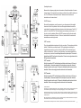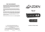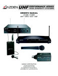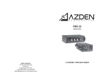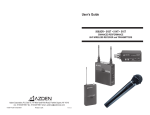
1
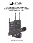
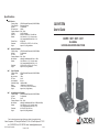
Specifications
320UPR Receiver
Frequency Range
Type of Reception
Oscillator
RF Squelch Level
Frequency Response
S/N Ratio
Audio Out
Batteries
External Power
Dimensions
Weight
30BT
Body-pack Transmitter
Frequency Range
UHF 240 Selectable Frequencies (794-805.950MHz)
Oscillator
PLL Synthesized
RF Power
15mW
Frequency Response 50Hz – 15kHz
Max. Deviation
±40kHz @ 1kHz Modulation, MIC Input – 11dBm
Batteries
2 “AA” Alkaline (2 x 1.5V) – 8-10 hours runtime
2 “AA” rechargeable Ni-MH or Ni-Cd (2 x 1.2V)
Dimensions
2.52"W x 3.94"H x 1.06"D (64 x 100 x 27 mm)
Weight
Approx. 4.54oz (160g) w/batteries
30XT
Plug-In Transmitter
Frequency Range
Antenna
Max. Input level
RF Power
Input Impedance
Audio Adjust. Range
Battery
Dimensions
Weight
30HT
320 SYSTEM
User’s Guide
UHF 240 Selectable Frequencies (794-805.950MHz)
Dual-channel Receiver
PLL Synthesized
13dBµV
50Hz – 15kHz
>70dB “A” Weighted
MIC Level – Unbalanced – 3.5mm Mini-Jack
2 “AA” Alkaline (2 x 1.5V) - 3-4 hours runtime
2 “AA” rechargeable Ni-MH or Ni-Cd (2 x 1.2V)
6VDC @ 0.5A
2.87"W x 4.45"H x 1.59"D (73 x 113 x 40.5 mm)
Approx. 9.17oz (260g) w/batteries
320UPR • 30BT • 30HT • 30XT
ON-CAMERA
UHF WIRELESS MICROPHONE SYSTEM
UHF 240 Selectable Frequencies (794-805.950MHz)
Internal
-7dBm
15mW
6k ohms
-63dBm to 18dBm
1 9V Alkaline – 6-8 hours runtime
1.57"W x 1.57"H x 3.9"L (40 x 40 x 99 mm)
Approx. 6.4oz (181.4g) w/battery
Handheld Microphone/Transmitter
Frequency Range
UHF 240 Selectable Frequencies (794-805.950MHz)
Oscillator
PLL Synthesized
RF Power
15mW
Frequency Response 50Hz – 15kHz
Max. Deviation
±40kHz @ 1kHz Modulation, MIC Input – 65dBm (dev ±5kHz)
Batteries
2 “AA” Alkaline (2 x 1.5V) – 8-10 hours runtime
2 “AA” rechargeable Ni-MH or Ni-Cd (2 x 1.2V)
Dimensions
Φ1.89" x 9.23"L (48 x 234.5 mm)
Weight
Approx. 4.23oz (245g) w/batteries
Due to constant improvements, specifications are subject to change without notice.
Azden Corporation, 147 New Hyde Park Road, P.O. Box 10, Franklin Square, NY 11010
vox - 516.328.7500 • fax - 516.328.7506 • email - [email protected]
© 2007 Azden Corporation
Printed in USA
P1070-01
Operating the system
19
6
Because this is a frequency agile system, the receiver and transmitter must be on the same
channel number. To change the channel number, use the tip of the provided tool and press
the UP or DOWN button to the desired channel. Make sure both the receiver and
transmitter are on the same channel.
4
320UPR Receiver
3
21
20
9
18
17
7
8
5
After installing new batteries, mount the receiver to your video camera with the supplied
shoe mount or hook & loop fastener. Select one of the supplied cables and connect the
output cable to the receiver and to the microphone input on the video camera. Switch Ch.1
and/or Ch.2 of the 320UPR to “ON” and the battery level indicator(s) should come on. If
they do not, check the batteries. When the 320UPR receives a signal from the transmitter
the reception level indicator will come on. If it does not, make sure both the receiver and
transmitters are on matching channels.
30BT Transmitter
Plug in the supplied lapel microphone and clip it to your subject. The microphone should be
placed 4-12 inches from your subject’s mouth. Clip the transmitter to a belt using the
supplied belt-clip or place it in a pocket. Switch the 30BT to “ON” and the battery level
indicator should come on. If it does not, check the battery. Have someone speak into the
microphone as you monitor the sound through the receiver’s phone output. If the sound is
distorted lower the MIC input level on the transmitter. If there is not enough volume raise the
MIC input level on the transmitter.
16
1
2
12
30XT Transmitter
Switch the transmitter to “ON” and the battery level indicator should come on. If it does not,
check the battery. Have someone speak into the microphone as you monitor the sound
through the camera’s monitor output. If the sound is distorted lower the level control on the
transmitter. If there is not enough gain raise the level control on the transmitter.
11
27
25
24
+
13
23
23
15
Belt Clip
-
22
14
+
30HT Transmitter
Switch the transmitter to “ON” and the battery level indicator should come on. If it does not,
check the battery. Have someone speak into the microphone as you monitor the sound
through the camera’s monitor output. If the sound is distorted lower the level control on the
transmitter. If there is not enough gain raise the level control on the transmitter.
Important information
Licensing of this, or any Azden wireless equipment is the user’s responsibility. The ability to receive a license depends largely on the
user’s classification, application and frequency. Contact the appropriate agency (FCC in the US) for further information.
These devices comply with Part 15 of the FCC Rules. Operation is subject to the following two conditions: (1) These devices may not
cause harmful interference, and (2) These devices must accept any interference received, including interference that may cause
undesired operation.
10
26
NOTE: The manufacturer is not responsible for any radio or TV interference caused by unauthorized modifications to this equipment.
Such modifications could void the user's authority to operate the equipment.
These devices and their antenna(s) must not be co-located or operated in conjunction with any other antenna or transmitter.
5
(21) LCD Display:
The display will light up when the power is turned “ON”. The LCD display shows the
following information.
Channels number: 001 to 240
Battery Condition: Using a 3 step indicator – 1(Low) to 3 (High)
To change the channel number, use the tip of the tool provided and press the UP or DOWN
button until the desired channel number appears (001 to 240). Once the desired channel
number has been selected on the transmitter, set the receiver to the same channel number.
HANDHELD MICROPHONE/TRANSMITTER (30HT)
(22) Remove the battery compartment cover by rotating it counterclockwise and sliding it
down.
(23) Insert two fresh Alkaline “AA” batteries into the compartment. Make sure the battery
polarity is correct as marked inside the battery compartment.
In the battery compartment you will also find:
(24) MIC LEVEL Control
The MIC LEVEL control enables you to adjust the audio level of the microphone. Using the
supplied tool, turn the dial clockwise to increase, or counterclockwise to decrease the
microphone’s audio level.
(25) UP/DOWN Channel Buttons
To change the channel number, use the tip of the tool provided and press the UP or DOWN
button until the desired channel number appears (001 to 240). Once the desired channel
number has been selected on the transmitter, set the receiver to the same channel number.
(26) POWER
Switches the transmitter “ON” or “OFF”.
(27) LCD Display:
The display will light up when the power is turned “ON”. The LCD display shows the
following information.
Channel number: 001 to 240.
Battery Condition: Using a 3 step indicator - 1 (Low) to 3 (High)
Thank you for purchasing Azden’s 320 wireless microphone system. Depending on
which system you ordered this package will contain one or more of the following components: the 320UPR receiver, the 30BT body-pack transmitter with EX-503L lavalier microphone, the 30XT XLR plug-in transmitter and/or the 30HT handheld microphone
transmitter. This equipment is designed primarily for video cameras but is usable with
most electronic components having a microphone level input. The 320UPR allows you to
“receive” audio from two different transmitters simultaneously.
RECEIVER (320UPR)
(1) Remove the battery compartment lid by sliding it down.
(2) Insert two fresh alkaline “AA” batteries into the compartment. Make sure the battery
polarity is correct as marked inside the battery compartment.
(3) POWER (one switch for each channel)
Switches the receiver CH1 and/or CH2 “ON” or “OFF”.
(4) MIC OUT jack:
The 320UPR is supplied with both a mini-to-mini and a mini-to-dual XLR cable.
For mini jack microphone inputs: Use the supplied mini-to-mini cable. Plug one
end of the cable into the receiver and the other end of the cable into the microphone input of the video camera.
For 3-pin XLR microphone inputs: Use the supplied mini-to-dual XLR cable. Plug
the mini-plug end of the cable into the receiver (use the screw-down sleeve to secure it to the receiver) and plug the XLR ends of the cable into the microphone
inputs of the video camera. Ch.1 is on the “Tip” connector, Ch.2 is on the “Ring”.
(5) LCD Display:
There are two displays, one for CH1 and one for CH2. The display for each channel will
light up when the power for that channel is turned “ON”. The LCD displays show the
following identical information.
Channel Number: 001 to 240
Battery Condition: Using a 3-step indicator - 1 (Low) to 3 (High)
Reception Level: Using a 4-step indicator - 1 (Low) to 4 (High)
To change the channel number, use the tip of the tool provided and press the UP or
DOWN button until the desired channel number appears ( 001 to 240). Once the desired
channel number has been selected on the receiver, set the transmitter to the same
channel number.
NOTE: When using two transmitters with the 320UPR please do the following:
4
1
A) Make sure that you use 2 different channel numbers that are at least 10 numbers
apart. This will prevent possible crosstalk between the 2 channels being used. For example: If you use channel number 10 for one transmitter, use channel number 20 for the
other transmitter. The 2 channels on the receiver must also be set on the numbers 10
and 20.
(14) MIC Input Jack
Plug the supplied EX-503L microphone into the MIC input jack and tighten the collar until
snug (DO NOT OVERTIGHTEN). In addition to the EX-503L, other lapel and/or headset
microphones with 3.5mm mini plugs can also be used with the 30BT.
(15) LCD Display
B) The system will operate properly if both transmitters are in close proximity to each
other, however make sure that both transmitters are at least 10 feet away from the receiver, this will prevent the frequencies from overlapping.
(6) PHONE jack:
Plug a stereo headphone into this jack to monitor sound - Ch. 1 will be heard on the left,
Ch. 2 on the right.
(7) DC 6 Volt Input: An optional charger/power supply and rechargeable batteries are
available for the 320UPR. For additional information or to order these products please
visit the Azden website at www.azdencorp.com or contact your Azden dealer.
NOTE: Using a power supply of the wrong voltage/current may damage the unit
and void the warranty.
(8) Shoe Stand:
Attach the 320UPR to the shoe-mount of the video camera by sliding it into place. Turn
the thumbwheel clockwise to tighten. Reverse this procedure to remove the 320UPR
from the camera.
(9) Antennas: For best reception the antennas should be pointed in an upward fashion.
Use caution, and do not force them into this position.
BODYPACK TRANSMITTER (30BT)
(10) Remove the battery compartment lid by sliding it down.
(11) Insert two fresh “AA” batteries* into the compartment. Make sure the battery polarity
is correct as marked inside the battery compartment.
In addition to the battery, inside the battery compartment you will find:
(12) MIC Input LEVEL Control
This control enables you to adjust the input level of the microphone. Using the supplied
tool, turn the dial clockwise to increase, or counterclockwise to decrease the input level.
(13) POWER
Switches the transmitter “ON” or “OFF”.
2
This display shows the following information.
Channel Number: 001 to 240
Battery Condition: Using a 3 step indicator - 1 (Low) to 3 (High)
To change the channel number: Use the tip of the tool provided and press the UP or
DOWN button to the desired channel, number appears (001 to 240). Once the desired
channel number has been selected on the transmitter, set the receiver to the same
channel number.
*While Alkaline batteries are preferred, you can use rechargeable Ni-Cd or Ni-MH batteries.
XLR PLUG-IN TRANSMITTER (30XT)
(16) Open the battery compartment lid by sliding it down and lifting it up.
Insert a 9 volt Alkaline battery into the compartment. Make sure the battery polarity is correct as marked inside the battery compartment.
(17) POWER
Switches the transmitter “ON” or “OFF”.
(18) AUDIO
Prior to first turning the 30XT “ON” it is best to set the AUDIO switch to “OFF”. When
you are ready to begin transmitting, switch to “ON”. The “OFF” position acts as a
“mute” that maintains the RF signal but turns off the audio.
(19) MIC Connector/Locking Ring
This 3-pin XLR connector is the microphone input. Any low impedance microphone
with a corresponding connector can be attached here.
Once the microphone is plugged into the 30XT the locking ring should be rotated clockwise until snug. To remove the microphone, first rotate the locking
ring counterclockwise and then, while pressing the XLR release, pull the microphone away from the 30XT.
(20) MIC Input LEVEL Control
The MIC input LEVEL control enables you to adjust the input level of the connected
microphone. Using the supplied tool, turn the dial clockwise to increase, or
counterclockwise to decrease the input level
3